


 Loading...
SERVICE MANUAL
FLAT COLOUR TELEVISION
AV-29WX11/G AV-29WX11/S AV-29WX11/U AV-2932W1/E
BASIC CHASSIS
CH3
RM-C1306
RM-C1309
RM-C1306-1H RM-C1309-1H [AV-29WX11/G] [AV-2932W1/E] [AV-29WX11/S]
[AV-29WX11/U]
TABLE OF CONTENTS
1 |
PRECAUTION ......................................................................................................................................................... |
1-3 |
2 |
SPECIFIC SERVICE INSTRUCTIONS ................................................................................................................... |
1-4 |
3 |
DISASSEMBLY ....................................................................................................................................................... |
1-7 |
4 |
ADJUSTMENT ...................................................................................................................................................... |
1-14 |
5 |
TROUBLESHOOTING ........................................................................................................................................... |
1-31 |
COPYRIGHT © 2003 VICTOR COMPANY OF JAPAN, LTD.
No.52197
2003/9

SPECIFICATION
Items |
|
|
Contents |
|
|
|
|
AV-29WX11/G, AV-29WX11/S, AV-29WX11/U |
|
AV-2932W1/E |
|
|
|
|
|
||
|
|
|
|
|
|
Dimensions (W × H × D) |
81.2cm x 58.4cm x 51.8cm |
|
|||
Mass |
|
43kg |
|
|
|
TV RF System |
|
B, G, I, D, K, M |
|
||
Colour System |
TV Mode |
PAL / SECAM / NTSC3.58 / NTSC4.43 |
|
||
|
Video Mode |
PAL / SECAM / NTSC3.58 / NTSC4.43 |
|
||
Stereo System |
|
Playback only |
|
||
Teletext system |
|
|
None |
|
FLOF (Fastext), |
|
|
|
|
WST (World Standard Text) |
|
|
|
|
|
|
|
Receiving Frequency |
VHF Low |
46.25MHz – 140.25MHz (AS0 – S6) |
|
||
|
VHF High |
147.25MHz – 423.25MHz (S7 – S36) |
|
||
|
UHF |
431.25MHz – 863.25MHz (S37 – CHINA 57) |
|
||
|
CATV |
Mid |
: X-Z, S1-S10 |
|
|
|
|
Super : S11-S20 |
|
||
|
|
Hyper : S21-S41 |
|
||
Intermediate |
VIF |
38.0MHz |
|
||
Frequency |
SIF |
31.5MHz (6.5MHz), 32.0MHz (6.0MHz), 32.5MHz (5.5MHz), 33.5MHz (4.5MHz) |
|||
Colour Sub Carrier Frequency |
4.43MHz (PAL), 4.40MHz/4.25MHz (SECAM), 3.58MHz/4.43MHz (NTSC) |
||||
Aerial Input Terminal |
|
75Ω unbalanced |
|
||
Power Input |
|
AC110V – AC240V, 50Hz / 60Hz |
|
||
Power Consumption |
|
177W (Max.) / 145W (Avg.) |
|
||
Picture Tube |
|
Visible size : 67.6cm (Diagonal) / 54.1cm x 40.6cm (H x V) |
|
||
High Voltage |
|
32kV -1.5kV / +1.0kV (at zero beam current) |
|
||
Speaker |
|
6.5cm × 13cm, Oval type × 2 |
|
||
Audio Output |
|
7W + 7W |
|
||
Video / Audio Input |
S-Video (1) |
Mini-DIN 4 pin × 1 |
|
||
(1 / 2 / 3) |
|
Y : 1V(p-p), positive (negative sync provided), 75Ω |
|
||
|
|
C : 0.286V(p-p) (Burst signal), 75Ω |
|
||
|
Video (1/2/3) |
1V(p-p), negative sync, 75Ω, RCA pin jack × 3 |
|
||
|
Audio (1/2/3) |
500mV(rms) ( -4dBs ), high impedance, RCA pin jack × 6 |
|
||
|
Component (2) |
RCA pin jack × 3 |
|
||
|
|
Y |
: 1V(p-p), positive (negative sync), 75Ω |
|
|
|
|
CB/CR: 0.7V(p-p), 75Ω |
|
||
Video / Audio Output |
Video |
1V(p-p), 75Ω, RCA pin jack × 1 |
|
||
|
Audio |
500mV(rms)(-4dBs), Low impedance (400Hz when modulated 100%), RCA pin jack × 2 |
|||
Headphone |
|
3.5mm stereo mini jack × 1 |
|
||
Remote Control Unit |
|
RM-C1306-1H |
|
RM-C1309-1H |
|
|
|
(AA/R06/UM-3 battery × 2) |
|
(AA/R06/UM-3 battery × 2) |
|
|
|
|
|
|
|
Design & specifications are subject to change without notice.
1-2 (No. 52197)
SECTION 1 PRECAUTION
1.1 SAFETYPRECAUTIONS
(1)The design of this product contains special hardware, many circuits and components specially for safety purposes. For continued protection, no changes should be made to the original design unless authorized in writing by the manufacturer. Replacement parts must be identical to those used in the original circuits. Service should be performed by qualified personnel only.
(2)Alterations of the design or circuitry of the products should not be made. Any design alterations or additions will void the manufacturer's warranty and will further relieve the manufacturer of responsibility for personal injury or property damage resulting therefrom.
(3)Many electrical and mechanical parts in the products have special safety-related characteristics. These characteristics are often not evident from visual inspection nor can the protection afforded by them necessarily be obtained by using replacement components rated for higher voltage, wattage, etc. Replacement parts which have these special safety characteristics are identified in the parts list of Service manual. Electrical components having such features are identified by shading on the schematics and by (!) on the parts list in Service manual.
The use of a substitute replacement which does not have the same safety characteristics as the recommended replacement part shown in the parts list of Service manual may cause shock, fire, or other hazards.
(4)Don't short between the LIVE side ground and ISOLATED (NEUTRAL) side ground or EARTH side ground when repairing.
Some model's power circuit is partly different in the GND. The difference of the GND is shown by the LIVE : (  ) side GND, the ISOLATED (NEUTRAL) : (
  ) side GND and
EARTH : (  ) side GND. Don't short between the LIVE side GND and ISOLATED (NEUTRAL) side GND or EARTH side GND and never measure the LIVE side GND and ISOLATED (NEUTRAL) side GND or EARTH side GND at the same time with a measuring apparatus (oscilloscope etc.).
If above note will not be kept, a fuse or any parts will be broken.
(5)If any repair has been made to the chassis, it is recommended that the B1 setting should be checked or adjusted (See ADJUSTMENT OF B1 POWER SUPPLY).
(6)The high voltage applied to the picture tube must conform with that specified in Service manual. Excessive high voltage can cause an increase in X-Ray emission, arcing and possible component damage, therefore operation under excessive high voltage conditions should be kept to a minimum, or should be prevented. If severe arcing occurs, remove the AC power immediately and determine the cause by visual inspection (incorrect installation, cracked or melted high voltage harness, poor soldering, etc.). To maintain the proper minimum level of soft X-Ray emission, components in the high voltage circuitry including the picture tube must be the exact replacements or alternatives approved by the manufacturer of the complete product.
(7)Do not check high voltage by drawing an arc. Use a high voltage meter or a high voltage probe with a VTVM. Discharge the picture tube before attempting meter connection, by connecting a clip lead to the ground frame and connecting the other end of the lead through a 10kΩ 2W resistor to the anode button.
(8)When service is required, observe the original lead dress. Extra precaution should be given to assure correct lead dress in the high voltage circuit area. Where a short circuit has occurred, those components that indicate evidence of overheating should be replaced. Always use the manufacturer's replacement components.
(9)Isolation Check
(Safety for Electrical Shock Hazard)
After re-assembling the product, always perform an isolation check on the exposed metal parts of the cabinet (antenna terminals, video/audio input and output terminals, Control knobs, metal cabinet, screw heads, earphone jack, control shafts, etc.) to be sure the product is safe to operate without danger of electrical shock.
a)Dielectric Strength Test
The isolation between the AC primary circuit and all metal parts exposed to the user, particularly any exposed metal part having a return path to the chassis should withstand a voltage of 3000V AC (r.m.s.) for a period of one second. (. . . . Withstand a voltage of 1100V AC (r.m.s.) to an appliance rated up to 120V, and 3000V AC (r.m.s.) to an appliance rated 200V or more, for a period of one second.) This method of test requires a test equipment not generally found in the service trade.
b)Leakage Current Check
Plug the AC line cord directly into the AC outlet (do not use a line isolation transformer during this check.). Using a "Leakage Current Tester", measure the leakage current from each exposed metal part of the cabinet, particularly any exposed metal part having a return path to the chassis, to a known good earth ground (water pipe, etc.). Any leakage current must not exceed 0.5mA AC (r.m.s.).
However, in tropical area, this must not exceed 0.2mA AC (r.m.s.).
Alternate Check Method
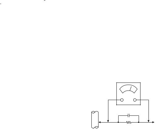
Plug the AC line cord directly into the AC outlet (do not use a line isolation transformer during this check.). Use an AC voltmeter having 1000 ohms per volt or more sensitivity in the following manner. Connect a 1500Ω 10W resistor paralleled by a 0.15µF AC-type capacitor between an exposed metal part and a known good earth ground (water pipe, etc.). Measure the AC voltage across the resistor with the AC voltmeter. Move the resistor connection to each exposed metal part, particularly any exposed metal part having a return path to the chassis, and measure the AC voltage across the resistor. Now, reverse the plug in the AC outlet and repeat each measurement. Any voltage measured must not exceed 0.75V AC (r.m.s.). This corresponds to 0.5mA AC (r.m.s.).
However, in tropical area, this must not exceed 0.3V AC (r.m.s.). This corresponds to 0.2mA AC (r.m.s.).
AC VOLTMETER (HAVING 1000Ω/V,
OR MORE SENSITIVITY)
0.15µF AC-TYPE |
|
|
|
PLACE THIS PROBE |
|
1500Ω 10W |
ON EACH EXPOSED |
|
METAL PART |
||
|
GOOD EARTH GROUND
(No. 52197) 1-3

SECTION 2
SPECIFIC SERVICE INSTRUCTIONS
2.1 FEATURES
•New chassis design enables use of an interactive on-screen control.
•Pure flat CRT produces fine textured picture in every detail.
•Wide range voltage (110V ~ 240V) for AC power input.
•With AUDIO/VIDEO/S-VIDEO/COMPONENT input terminals.
•I 2 C bus control utilizes single chip ICs.
•By means of AUTO PROGRAM, the TV stations can be selected automatically and the TV channels can also be rearranged automatically.
•Built-in DIGITAL ECO MODE (ECONOMY, ECOLOGY).
In accordance with the brightness in a room, the brightness and/or contrast of the picture can be adjusted automatically to make the optimum picture which is easy on the eye.
•Built-in OFF TIMER & RETURN +.
2.2 |
MAIN DIFFERENCE LIST |
|
|
|
|
|
|
|
|
|
|
|
|
|
|
|
|
|
|
|
|
|
|
|
|
|
|
|
|
! |
|
Items |
|
AV-29WX11/G |
AV-29WX11/S |
|
AV-29WX11/U |
AV-2932W1/E |
||||||
|
|
|
|
|
|
|
|
|
|
|
|
|
|
|
! |
|
MAIN PWB ASS’Y |
SCH-1182A-H2 |
ACH-1183A-H2 |
SCH-1185A-H2 |
SCH-1184A-H2 |
||||||||
! |
|
FRONT CABINET ASS’Y |
GG10189-002A-H |
← |
|
|
← |
GG10189-006A-H |
||||||
|
|
REMOTE CONTROL UNIT |
RM-C1306-1H |
← |
|
|
← |
RM-C1309-1H |
||||||
|
|
|
QMPR340-165-K2 |
QRPR370-165-E2 |
QMPR340-165-K2 |
|
||||||||
! |
|
POWER CORD |
|
|
|
|
|
|
|
|
|
|
|
← |
|
|
|
|
|
|
|
|
|
|
|
|
|||
|
|
|
|
|
|
|
|
|
|
|
|
|
|
|
|
|
TELETEXT |
None |
← |
|
|
← |
FLOF, WST |
||||||
1-4 (No. 52197)

2.3 |
FUNCTIONS |
|
|
|
|
|
! REMOTE CONTROL UNIT |
|
|
|
|
|
|
RM-C1306-1H [AV-29WX11/G, AV-29WX11/S, AV-29WX11/U] |
|
|
||||
|
1 |
|
1 |
MUTING key |
14 |
CINEMA SURROUND key |
|
|
|
|
|
|
|
|
2 |
13 |
2 |
COLOUR SYSTEM key |
15 |
ECO SENSOR key |
|
|
|
|
|
|
|
|
3 |
14 |
3 |
SOUND SYSTEM key |
16 |
Number keys |
|
|
|
|
|
|
|
|
4 |
15 |
4 |
DISPLAY key |
17 |
-/-- key |
|
|
|||||
|
5 |
|
5 |
MENU ( / , / ) keys |
18 |
VOLUME (-/+) keys |
|
|
|
||||
|
|
|
6 |
TV/VIDEO key |
|
|
|
6 |
|
7 |
OFF TIMER key |
|
|
|
7 |
|
|
|
||
|
16 |
|
|
|
|
|
|
8 |
8 |
PICTURE MODE key |
|
|
|
|
|
|
|
|||
|
|
|
|
|
|
|
|
9 |
17 |
9 |
CHANNEL SCAN key |
|
|
|
10 |
|
10 |
RETERN + key |
|
|
|
11 |
18 |
|
|
||
|
|
|
|
|
||
|
|
|
|
|
|
|
|
12 |
|
11 |
CHANNEL (-/+) keys |
|
|
|
|
|
12 |
FAVORITE CH keys |
|
|
|
RM-C1306 |
|
13 |
POWER key |
|
|
|
|
|
|
|
||
RM-C1309-1H [AV-2932W1/E] |
|
|
|
|
|
|
|
|
1 |
MUTING key |
15 |
SUB PAGE key |
|
1 |
|
|
COLOUR SYSTEM key |
16 |
STORE key |
|
2 |
17 |
2 |
|
|||
|
|
|
|
|
|
|
3 |
18 |
3 |
SOUND SYSTEM key |
17 |
POWER key |
|
|
|
|
|
|
|
|
4 |
19 |
4 |
DISPLAY key |
18 |
CINEMA SURROUND key |
|
|
|
|||||
5 |
|
5 |
MENU ( / , / ) keys |
19 |
ECO SENSOR key |
|
|
|
|
||||
|
20 |
6 |
TV/VIDEO key |
20 |
TV/TEXT key |
|
|
|
|
||||
6 |
|
7 |
OFF TIMER key |
21 |
Number keys |
|
|
|
|
||||
7 |
21 |
8 |
PICTURE MODE key |
22 |
-/-- key |
|
8 |
|
|||||
|
|
|
|
|
|
|
9 |
22 |
9 |
CHANNEL SCAN key |
23 |
VOLUME (-/+) keys |
|
|
|
|
|
|
|
|
10 |
|
10 |
RETERN + key |
24 |
INDEX key |
|
11 |
23 |
|
||||
|
|
|
|
|
||
|
|
|
|
|
|
|
12 |
24 |
11 |
CHANNEL (-/+) keys |
25 |
SIZE key |
|
13 |
|
|
|
|
|
|
25 |
12 |
FAVORITE CH keys |
26 |
CANCEL key |
|
|
|
|
|||||
14 |
|
|
|
|
|
|
|
13 |
REVEAL key |
27 |
MODE key |
|
|
15 |
26 |
|
||||
|
|
|
|
|
||
|
|
|
|
|
|
|
|
RM-C1309 |
14 |
HOLD key |
|
|
|
16 |
27 |
|
|
|
||
|
|
|
|
|
(No. 52197) |
1-5 |
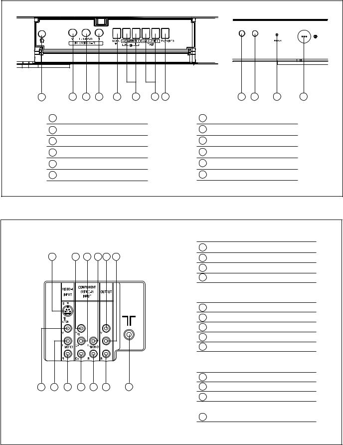
! FRONT PANEL CONTROLS
1 |
2 |
3 |
4 |
5 |
6 |
7 |
8 |
|
9 |
10 |
11 |
12 |
1 |
HEADPHONE jack |
|
|
|
|
7 |
VOLUME (-/+) buttons |
|
|
|||
2 |
IN (VIDEO-3) |
: VIDEO |
|
|
|
8 |
TV/VIDEO buttons |
|
|
|||
3 |
IN (VIDEO-3) |
: AUDIO L/MONO |
|
|
9 |
Remote control sensor |
|
|
||||
4 |
IN (VIDEO-3) |
: AUDIO R |
|
|
|
10 |
ECO sensor |
|
|
|
||
5 |
MENU ( ) button |
|
|
|
|
11 |
POWER lamp |
|
|
|
||
6 |
CHANNEL (-/+) buttons |
|
|
|
12 |
MAIN POWER button |
|
|
||||
! REAR TERMINAL
|
|
|
|
|
|
VIDEO-1 INPUT TERMINAL |
|
|
|
|
|
|
|
1 |
S-VIDEO |
1 |
5 |
6 |
8 |
10 |
11 |
2 |
VIDEO |
|
|
|
|
|
|
3 |
AUDIO L/MONO |
|
|
|
|
|
|
4 |
AUDIO R |
|
|
|
|
|
|
COMPONENT (VIDEO-2) INPUT TERMINAL |
|
|
|
|
|
|
|
5 |
Y/VIDEO |
|
|
|
|
|
|
6 |
CB |
|
|
|
|
|
|
7 |
CR |
|
|
|
|
|
|
8 |
AUDIO L/MONO |
|
|
|
|
|
|
9 |
AUDIO R |
|
|
|
|
|
|
OUTPUT TERMINAL |
|
|
|
|
|
|
|
10 |
VIDEO |
2 3 4 |
7 |
9 |
|
12 |
13 |
11 |
AUDIO L |
|
|
|
|
|
|
12 |
AUDIO R |
|
|
|
|
|
|
13 |
Aerial input terminal |
1-6 (No. 52197)
SECTION 3
DISASSEMBLY
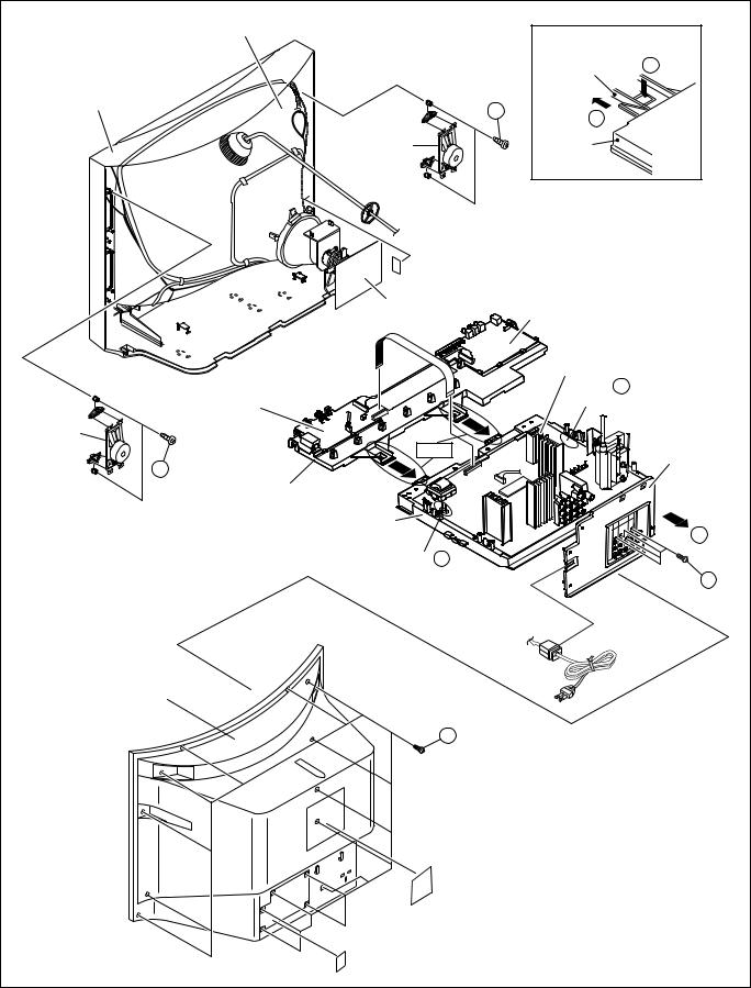
3.1 DISASSEMBLY PROCEDURE 3.1.1 REMOVING THE REAR COVER
•Unplug the power cord.
(1)Remove the 16 screws [A] as shown in Fig.1.
(2)Withdraw the REAR COVER toward you.
CAUTION:
When reinstalling the rear cover, carefully push it inward after inserting the MAIN PWB into the REAR COVER groove.
3.1.2REMOVING THE CHASSIS (CHASSIS BASE AND CONTROL BASE)
•Remove the REAR COVER.
(1)Slightly raise the both sides of the CHASSIS by hand and remove the 2 claws [B] under the CHASSIS from the front cabinet as shown in Fig.1.
(2)Withdraw the CHASSIS backward.
(If necessary, take off the wire clamp, connector's etc.)
NOTE:
When conducting a check with power supplied, be sure to confirm that the CRT earth wire is connected to the CRT SOCKET PWB and the MAIN PWB.
3.1.3 REMOVING THEAV TERMINAL BOARD
•Remove the REAR COVER.
(1)Remove the 4 screws [C] as shown in Fig.1.
(2)When you pull out the AV TERMINAL BOARD in the direction of arrow [D] as shown in Fig.1, it can be removed.
3.1.4 REMOVING THE CONTROL BASE
•Remove the REAR COVER.
•Remove the CHASSIS.
(1)While pushing down the 2 claws [E] as shown in Fig. 2 and pull out the CONTROL BASE in the direction of arrow [F] as shown in Fig. 2, the control base can be removed.
(If necessary, take off the wire, connector's etc.)
3.1.5 REMOVINGTHESPEAKER
•Remove the REAR COVER.
(1)Remove the 2 screws [G] as shown in Fig.1.
(2)Withdraw the SPEAKER backward.
(3)Follow the same steps when removing the other hand SPEAKER.
3.1.6 CHECKING THE MAIN PW BOARD
•To check the back side of the MAIN PWB.
(1)Pull out the CHASSIS. (Refer to REMOVING THE CHASSIS).
(2)Erect the CHASSIS vertically so that you can easily check the back side of the MAIN PWB.
CAUTIONS:
•When erecting the chassis, be careful so that there will be no contacting with other PW Board.
•Before turning on power, make sure that the CRT earth wire and other connectors are properly connected.
•When repairing, connect the DEG. COIL to the DEG. connector on the MAIN PWB.
3.1.7 WIRE CLAMPING AND CABLE TYING
(1)Be sure to clamp the wire.
(2)Never remove the cable tie used for tying the wires together.
Should it be inadvertently removed, be sure to tie the wires with a new cable tie.
(No. 52197) 1-7
|
PICTURE TUBE |
|
|
|
|
[FRONT SIDE] |
|
|
|
CONTROL BASE |
E |
FRONT CABINET |
(X2) |
|
|
G |
|
|
|
|
F |
|
|
|
|
|
|
|
SPEAKER |
CHASSIS |
|
|
|
BASE |
|
|
|
Fig.2 |
|
|
CRT |
|
|
|
SOCKET PWB |
FRONT CONTROL PWB (2/2) |
|
|
|
||
|
|
MAIN PWB |
|
|
|
CLAW B |
|
|
FRONT CONTROL |
(under side) |
|
|
PWB (1/2) |
|
|
SPEAKER |
|
|
AV TERMINAL |
|
Fig.2 |
|
|
|
|
BOARD |
|
|
|
|
|
G |
(X2) |
|
|
|
CONTROL BASE |
|
|
|
CHASSIS |
|
|
|
BASE |
|
D |
|
CLAW B |
|
|
|
(under side) |
|
C |
|
|
|
|
|
|
|
(×4) |
REAR COVER |
|
|
|
|
A (×16) |
|
|
Fig. 1
1-8 (No. 52197)
3.2 REPLACEMENT OF MEMORY IC 3.2.1 MEMORY IC
This TV uses the following memory IC.
Memory IC: IC1702 on MAIN PW Board
The memory IC memorizes data for correctly operating the video and deflection circuits. When replacing the memory IC, be sure to use the same type IC written with the initial values of data. In other words, use the specific IC listed in “PRINTED WIRING BOARD PARTS LIST”. For its mounting location, refer to “ADJUSTMENT LOCATIONS”.
3.2.2PROCEDURE FOR REPLACING MEMORY IC
1.Power off
Switch the power off and unplug the power cord from the wall outlet.
2.Replacing the memory IC
Replace the memory IC with new one. Be sure to use the memory IC written with the initial data values.
3.Power on
Plug the power cord into the wall outlet and switch the power on.
4.Check and setting of SYSTEM CONSTANT SET:
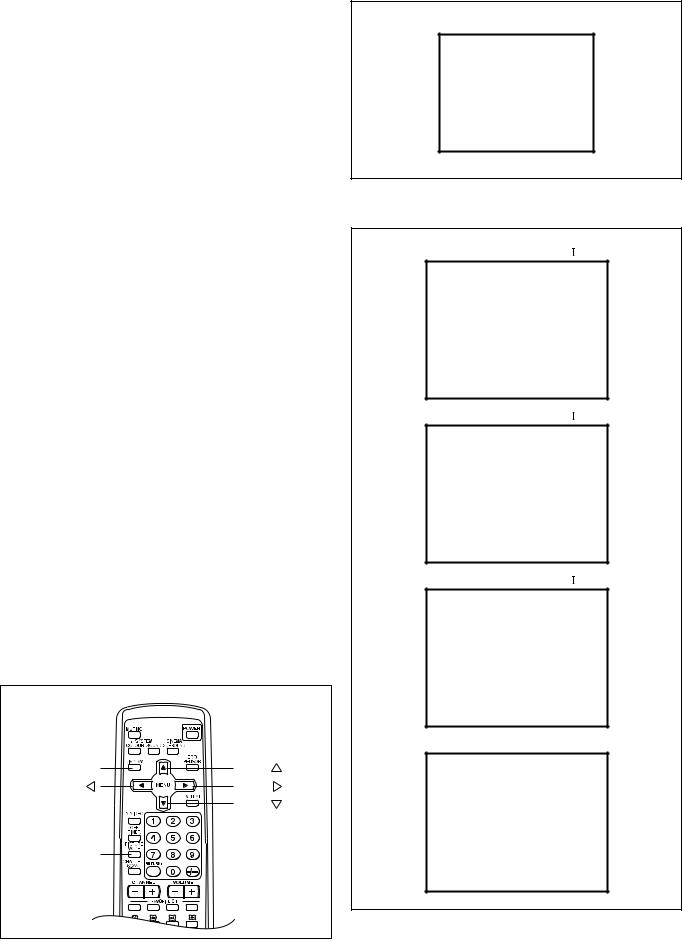
(1)Press the [DISPLAY] key and the [PICTURE MODE] key on the remote control unit simultaneously. The SERVICE MENU screen will be displayed.(See Fig.1.)
(2)In the SERVICE MENU, press the [DISPLAY] key and [PICTURE MODE] key simultaneously. Then, the SYSTEM CONSTANT SET screen will be displayed.(See Fig.2.)
(3)Check whether the setting values of the SYSTEM CONSTANT SET are the same as those indicated in Table1.
If the value is different, select the setting item with the MENU [!]/["] key, and set the correct value with the MENU [#]/[$] key.
(4)Press the [DISPLAY] key twice to return to the normal screen.
5.Receive channel setting
Refer to the OPERATING INSTRUCTIONS and set the receive channels (channels preset).
6.User setting
Check the user setting values in Table 2 and Table 3. If setting value is different, set the correct value.
For setting, refer to the OPERATING INSTRUCTIONS.
7.Setting of SERVICE MENU
Verify the setting for each setting item in the SERVICE MENU.(See Table 4.) If readjustment is necessary, perform adjustment referring to “ADJUSTMENTS PROCEDURE”.
NAME OF REMOTE CONTROL KEYS
DISPLAY |
MENU |
MENU |
MENU |
|
MENU |
PICTURE |
|
MODE |
|
SERVICE MENU
|
SERVICE MENU |
1. IF |
2. VC |
3. DEF |
4. VSM PRESET |
5.PRESET
6.PLUG & PLAY (ON)
1-6 : SELECT DISPLAY : EXIT
******* **** ***** *****
**** **** *** ***
Fig. 1
SYSTEM CONSTANT-
SYSTEM CONSTANT SET 1
SYSTEM |
MULTI |
COMB |
YES |
TILT |
YES |
SUPER BASS |
NO |
TEXT |
ERAPU |
LANGUAGE |
E/R/A/P/U |
: SEL - + : OPE DISP : EXIT
SYSTEM CONSTANT-
SYSTEM CONSTANT SET 2
MSP |
NO |
BILINGUAL |
NO |
B / B SOUND |
NO |
TUNER |
MU |
COLOUR AUTO |
NO |
: SEL - + : OPE DISP : EXIT
SYSTEM CONSTANT-
SYSTEM CONSTANT SET 3
LOCK |
1 MHz |
: 040 |
|
500 KHz |
: 040 |
|
250 KHz |
: 040 |
|
156. 25 KHz |
: 030 |
31.25KHz : 030
: SEL - + : OPE DISP : EXIT
SYSTEM CONSTANT-
SYSTEM CONSTANT SET 4
3D SURROUND |
YES |
AMP TUNER |
NO |
COMPONENT |
YES |
PIP |
NO |
16 : 9 |
YES |
M.L. delete |
ON |
: SEL - + : OPE DISP : EXIT
Fig. 2
(No. 52197) 1-9

3.2.3 FACTORY SETTING VALUE !SETTING OF SYSTEM CONSTANT SET
Setting item |
|
|
|
|
|
Setting content |
|
|
|
|
|
|
|
|
Setting value |
|
||||||||
|
|
|
|
|
|
|
|
|
|
|
|
AV-29WX11/G |
AV-29WX11/S |
AV-29WX11/U |
AV-2932W1/E |
|||||||||
|
|
|
|
|
|
|
|
|
|
|
|
|
|
|
|
|
|
|
|
|
||||
|
|
|
|
|
|
|
|
|
|
|
|
|
|
|
|
|
|
|
|
|
|
|
|
|
SYSTEM |
|
MULTI |
TRIPLE |
PAL SINGLE VIET |
|
|
MULTI |
← |
← |
← |
||||||||||||||
|
|
|||||||||||||||||||||||
|
|
|
|
|
|
|
|
|
|
|
|
|
|
|
|
|
|
|
|
|||||
|
|
|
|
|
|
|
|
|
|
|
|
|
|
|
|
|
|
|
|
|
|
|
|
|
COMB |
|
|
|
|
|
YES |
NO |
|
|
|
|
|
|
|
|
|
|
|
|
YES |
← |
← |
← |
|
|
|
|
|
|
|
|
|
|
|
|
|
|
|
|
||||||||||
|
|
|
|
|
|
|
|
|
|
|
|
|
|
|
|
|
|
|
|
|||||
|
|
|
|
|
|
|
|
|
|
|
|
|
|
|
|
|
|
|
|
|
|
|
|
|
TILT |
|
|
|
|
|
YES |
NO |
|
|
|
|
|
|
|
|
|
|
|
|
YES |
← |
← |
← |
|
|
|
|
|
|
|
|
|
|
|
|
|
|
|
|
||||||||||
|
|
|
|
|
|
|
|
|
|
|
|
|
|
|
|
|
|
|
|
|||||
|
|
|
|
|
|
|
|
|
|
|
|
|
|
|
|
|
|
|
|
|
|
|
|
|
SUPER BASS |
|
|
|
|
|
YES |
NO |
|
|
|
|
|
|
|
|
|
|
NO |
← |
← |
← |
|||
|
|
|
|
|
|
|
|
|
|
|
|
|
|
|||||||||||
|
|
|
|
|
|
|
|
|
|
|
|
|
|
|
|
|
|
|
|
|||||
|
|
|
|
|
|
|
|
|
|
|
|
|
|
|
|
|
|
|
|
|
|
|
|
|
TEXT |
|
|
|
|
ERCMI |
ERAPU |
NO |
|
|
NO |
← |
← |
ERAPU |
|||||||||||
|
|
|
|
|
||||||||||||||||||||
|
|
|
|
|
|
|
|
|
|
|
|
|
|
|
|
|
|
|
|
|||||
|
|
|
|
|
|
|
|
|
|
|
|
|
|
|
|
|
|
|
|
|
|
|
|
|
LANGUAGE |
|
|
|
|
E/R/A/P/U |
|
E/R/A/P |
E/R/U |
|
|
E/R/A/P |
← |
← |
E/R/A/P/U |
||||||||||
|
|
|
|
|
|
|||||||||||||||||||
|
|
|
|
|
|
|
|
|
|
|
|
|
|
|
|
|
|
|
|
|||||
|
|
|
|
|
|
|
|
|
|
|
|
|
|
|
|
|
|
|
|
|
|
|
|
|
MSP |
|
|
|
|
|
YES |
NO |
|
|
|
|
|
|
|
|
NO |
← |
← |
← |
|||||
|
|
|
|
|
|
|
|
|
|
|
|
|
||||||||||||
|
|
|
|
|
|
|
|
|
|
|
|
|
|
|
|
|
|
|
|
|||||
|
|
|
|
|
|
|
|
|
|
|
|
|
|
|
|
|
|
|
|
|
|
|
|
|
BILINGUAL |
|
|
|
|
|
YES |
NO |
|
|
|
|
|
|
|
|
NO |
← |
← |
← |
|||||
|
|
|
|
|
|
|
|
|
|
|
|
|
||||||||||||
|
|
|
|
|
|
|
|
|
|
|
|
|
|
|
|
|
|
|
|
|||||
|
|
|
|
|
|
|
|
|
|
|
|
|
|
|
|
|
|
|
|
|
|
|
|
|
B/B SOUND |
|
|
|
|
|
YES |
NO |
|
|
|
|
|
|
|
|
NO |
YES |
NO |
← |
|||||
|
|
|
|
|
|
|
|
|
|
|
|
|
||||||||||||
|
|
|
|
|
|
|
|
|
|
|
|
|
|
|
|
|
|
|
|
|||||
|
|
|
|
|
|
|
|
|
|
|
|
|
|
|
|
|
|
|
|
|
|
|
|
|
TUNER |
|
|
|
|
|
MU |
MA |
|
|
|
|
|
|
|
|
MU |
← |
← |
← |
|||||
|
|
|
|
|
|
|
|
|
|
|
|
|
||||||||||||
|
|
|
|
|
|
|
|
|
|
|
|
|
|
|
|
|
|
|
|
|||||
|
|
|
|
|
|
|
|
|
|
|
|
|
|
|
|
|
|
|
|
|
|
|
|
|
COLOUR AUTO |
|
|
|
|
|
YES |
NO |
|
|
|
|
|
|
|
|
NO |
YES |
NO |
← |
|||||
|
|
|
|
|
|
|
|
|
|
|
|
|
||||||||||||
|
|
|
|
|
|
|
|
|
|
|
|
|
|
|
|
|
|
|
|
|||||
|
|
|
|
|
|
|
|
|
|
|
|
|
|
|
|
|
|
|
|
|
|
|
|
|
LOCK 1MHz |
|
|
|
|
|
000 |
|
240 |
|
|
|
|
|
|
|
|
|
|
|
|
040 |
← |
← |
← |
|
|
|
|
|
|
|
|
|
|
|
|
|
|
|
|
|
|
|||||||
|
|
|
|
|
|
|
|
|
|
|
|
|
|
|
|
|
|
|
|
|||||
|
|
|
|
|
|
|
|
|
|
|
|
|
|
|
|
|
|
|
|
|
|
|
|
|
500KHz |
|
|
|
|
|
000 |
|
240 |
|
|
|
|
|
|
|
|
|
|
|
|
040 |
← |
← |
← |
|
|
|
|
|
|
|
|
|
|
|
|
|
|
|
|
|
|
|||||||
|
|
|
|
|
|
|
|
|
|
|
|
|
|
|
|
|
|
|
|
|||||
|
|
|
|
|
|
|
|
|
|
|
|
|
|
|
|
|
|
|
|
|
|
|
|
|
250KHz |
|
|
|
|
|
000 |
|
240 |
|
|
|
|
|
|
|
|
|
|
|
|
040 |
← |
← |
← |
|
|
|
|
|
|
|
|
|
|
|
|
|
|
|
|
|
|
|||||||
|
|
|
|
|
|
|
|
|
|
|
|
|
|
|
|
|
|
|
|
|||||
|
|
|
|
|
|
|
|
|
|
|
|
|
|
|
|
|
|
|
|
|
|
|
|
|
156.25KHz |
|
|
|
|
|
000 |
|
240 |
|
|
|
|
|
|
|
|
|
|
|
|
030 |
← |
← |
← |
|
|
|
|
|
|
|
|
|
|
|
|
|
|
|
|
|
|
|||||||
|
|
|
|
|
|
|
|
|
|
|
|
|
|
|
|
|
|
|
|
|||||
|
|
|
|
|
|
|
|
|
|
|
|
|
|
|
|
|
|
|
|
|
|
|
|
|
31.25KHz |
|
|
|
|
|
000 |
|
240 |
|
|
|
|
|
|
|
|
|
|
|
|
030 |
← |
← |
← |
|
|
|
|
|
|
|
|
|
|
|
|
|
|
|
|
|
|
|||||||
|
|
|
|
|
|
|
|
|
|
|
|
|
|
|
|
|
|
|
|
|||||
|
|
|
|
|
|
|
|
|
|
|
|
|
|
|
|
|
|
|
|
|
|
|
|
|
3D SURROUND |
|
|
|
|
|
YES |
NO |
|
|
|
|
|
|
|
|
YES |
← |
← |
← |
|||||
|
|
|
|
|
|
|
|
|
|
|
|
|
||||||||||||
|
|
|
|
|
|
|
|
|
|
|
|
|
|
|
|
|
|
|
|
|||||
|
|
|
|
|
|
|
|
|
|
|
|
|
|
|
|
|
|
|
|
|
|
|
|
|
AMP TUNER |
|
|
|
|
|
YES |
NO |
|
|
|
|
|
|
|
|
NO |
← |
← |
← |
|||||
|
|
|
|
|
|
|
|
|
|
|
|
|
||||||||||||
|
|
|
|
|
|
|
|
|
|
|
|
|
|
|
|
|
|
|
|
|||||
|
|
|
|
|
|
|
|
|
|
|
|
|
|
|
|
|
|
|
|
|
|
|
|
|
COMPONENT |
|
|
|
|
|
YES |
NO |
|
|
|
|
|
|
|
|
YES |
← |
← |
← |
|||||
|
|
|
|
|
|
|
|
|
|
|
|
|
||||||||||||
|
|
|
|
|
|
|
|
|
|
|
|
|
|
|
|
|
|
|
|
|||||
|
|
|
|
|
|
|
|
|
|
|
|
|
|
|
|
|
|
|
|
|
|
|
|
|
PIP |
|
|
|
|
|
YES |
NO |
|
|
|
|
|
|
|
|
NO |
← |
← |
← |
|||||
|
|
|
|
|
|
|
|
|
|
|
|
|
||||||||||||
|
|
|
|
|
|
|
|
|
|
|
|
|
|
|
|
|
|
|
|
|||||
|
|
|
|
|
|
|
|
|
|
|
|
|
|
|
|
|
|
|
|
|
|
|
|
|
16 : 9 |
|
|
|
|
|
YES |
NO |
|
|
|
|
|
|
|
|
YES |
← |
← |
← |
|||||
|
|
|
|
|
|
|
|
|
|
|
|
|
||||||||||||
|
|
|
|
|
|
|
|
|
|
|
|
|
|
|
|
|
|
|
|
|||||
|
|
|
|
|
|
|
|
|
|
|
|
|
|
|
|
|
|
|
|
|
|
|
|
|
M.L. delete |
|
|
|
|
|
ON |
|
OFF |
|
|
|
|
|
|
|
|
ON |
← |
← |
← |
||||
|
|
|
|
|
|
|
|
|
|
|
|
|
|
|||||||||||
|
|
|
|
|
|
|
|
|
|
|
|
|
|
|
|
|
|
|
|
|||||
|
|
|
|
|
|
|
|
|
|
|
|
|
|
|
|
|
|
|
|
|
|
|
|
|
Table 1
1-10 (No. 52197)
Loading...