


 Loading...
JVC AV-36320/M, AV-36320/R, AV-36330/M, AV-36330/R, AV-36360/M Service Manual
...AV-36360 AV-36S36
AV-36330 AV-36S33
AV-36320
SERVICE MANUAL
COLOR TELEVISION
AV-36360/M /R |
AV-36S36/M /R |
BASIC CHASSIS |
|
|
|
|
|
|
AV-36330/M /R |
AV-36S33/M /R |
GE |
|
||
|
||
AV-36320/M /R |
|
|
[RM-C254] AV-36360 AV-36S36
[RM-C255]
AV-36330
AV-36S33 [RM-C205] AV-36320
CONTENTS
!SPECIFICATIONS 2
!SAFETY PRECAUTIONS 3
!FEATURES 4
!FUNCTIONS 4
!MAIN DIFFERENCE LIST 6
!HOW TO INDENTIFY MODELS 7
!SPECIFIC SERVICE INSTRUCTIONS 8
!SERVICE ADJUSTMENTS 14
!PARTS LIST 35
STANDARD CIRCUIT DIAGRAM 2-1
1 |
COPYRIGHT © 2002 VICTOR COMPANY OF JAPAN, LTD. |
No.51950 |
|
|
May 2002 |

AV-36360 AV-36S36
AV-36330 AV-36S33
AV-36320
SPECIFICATIONS
|
|
|
|
|
CONTENTS |
|
|
|
|
ITEMS |
|
|
|
|
|
|
|
AV-36360/M /R |
|
|
AV-36330/M /R |
|
|
AV-36320/M /R |
||
|
|
|
|
|
|
|||
|
|
AV-36S36/M /R |
|
|
AV-36S33/M /R |
|
|
|
Dimensions (W×H×D) |
33-7/8”×30-1/8”×23-3/4” 860mm×765mm×603mm |
|
|
|
||||
Mass |
149.2Ibs / 67.8kg |
|
|
|
|
|
|
|
|
|
|
|
|
|
|
|
|
Systems |
|
|
|
|
|
|
|
|
|
TV RF System |
CCIR(M) |
|
|
|
|
|
|
|
Color System |
NTSC-M |
|
|
|
|
|
|
|
Sound System |
BTSC (Multi Channel Sound) |
|
|
|
|
|
|
RF Channels and Frequency |
|
|
|
|
|
|
|
|
|
VL Band |
(02 06) 54MHz 88MHz |
|
|
|
|
|
|
|
VH Band |
(07 13) 174MHz 216MHz |
|
|
|
|
|
|
|
UHF Band |
(14 69) 470MHz 806MHz |
|
|
|
|
|
|
CATV receivable band |
Low, High, Mid, Super, Hyper, Ultra and Sub Mid band available. Totally 180 channels. |
|||||||
|
|
|
|
|
|
|
|
|
Video IF Carrier |
45.75 MHz |
|
|
|
|
|
|
|
Sound IF Carrier |
41.25 MHz (4.5MHz) |
|
|
|
|
|
|
|
Color Sub Carrier |
3.58 MHz |
|
|
|
|
|
|
|
|
|
|
|
|
|
|
|
|
Picture Tube |
36” (90cm) measured diagonally |
|
|
|
|
|
|
|
Aspect ratio |
4:3 |
|
|
|
|
|
|
|
High Voltage |
31±1.3kV (at zero beam current) |
|
|
|
|
|
|
|
|
|
|
|
|
|
|
||
Power Input |
120V AC, 60Hz |
|
120V AC, 60Hz |
|
120V AC, 60Hz |
|||
Power Consumption |
133W |
|
130W |
|
130W |
|||
|
|
|
|
|
|
|
||
Comb filter |
3 line digital comb filter |
|
3 line digital comb filter |
|
3 line digital comb filter |
|||
Picture-In-Picture |
2 tuner PIP |
|
NO |
|
|
NO |
||
Hyper surround |
YES |
|
YES |
|
|
NO |
||
Language options |
English, French and Spanish |
|
English, French and Spanish |
|
English, French and Spanish |
|||
V-CHIP |
US / CA |
|
US / CA |
|
|
US / CA |
||
On / Off, Sleep timer |
YES |
|
YES |
|
|
YES |
||
|
|
|
|
|
|
|
|
|
Speaker |
3-1/4”×4-3/4” (8×12cm) |
|
3-1/4”×4-3/4” (8×12cm) |
|
|
3-1/4”×4-3/4” (8×12cm) |
||
Oval type×2 |
|
Oval type×2 |
|
|
Oval type×2 |
|||
|
|
|
|
|
||||
Audio Power Output |
3W+3W |
|
3W+3W |
|
|
3W+3W |
||
|
|
|
|
|
|
|
|
|
Input / Output terminals |
|
|
|
|
|
|
|
|
|
|
|
|
|
|
|
|
|
|
INPUT1 |
|
|
|
|
|
|
|
|
Video |
1Vp-p, 75Ω |
|
1Vp-p, 75Ω |
|
|
1Vp-p, 75Ω(superimposes Y) |
|
|
|
|
|
|||||
|
S-Video |
Y : 1Vp-p, negative sync |
|
Y : 1Vp-p, negative sync |
|
|
Y : 1Vp-p, negative sync |
|
|
C : 0.286Vp-p, 75Ω |
|
C : 0.286Vp-p, 75Ω |
|
|
C : 0.286Vp-p, 75Ω |
||
|
|
|
|
|
||||
|
Component (Y, Pb, Pr) |
--------- |
|
--------- |
|
|
YorV : 1Vp-p, negative sync |
|
|
|
|
|
Pb/Pr : 0.7Vp-p, 75Ω |
||||
|
|
|
|
|
|
|
|
|
|
Audio L/R |
0.5Vrms, high impedance |
|
0.5Vrms, high impedance |
|
0.5Vrms, high impedance |
||
|
|
|
|
|
|
|
|
|
|
INPUT2 |
|
|
|
|
|
|
|
|
Video |
1Vp-p, 75Ω |
|
1Vp-p, 75Ω |
|
|
1Vp-p, 75Ω |
|
|
|
|
|
|||||
|
Component (Y, Pb, Pr) |
YorV : 1Vp-p, negative sync |
|
YorV : 1Vp-p, negative sync |
|
--------- |
||
|
Pb/Pr : 0.7Vp-p, 75Ω |
|
Pb/Pr : 0.7Vp-p, 75Ω |
|
||||
|
|
|
|
|
|
|||
|
Audio L/R |
0.5Vrms, high impedance |
|
0.5Vrms, high impedance |
|
0.5Vrms, high impedance |
||
|
INPUT3 |
|
|
|
|
|
|
|
|
Video |
1Vp-p, 75Ω |
|
1Vp-p, 75Ω |
|
--------- |
||
|
Audio L/R |
0.5Vrms, high impedance |
|
0.5Vrms, high impedance |
|
--------- |
||
|
|
|
|
|
|
|
|
|
|
Audio Output (Fix) |
0.5Vrms, low Impedance, |
|
0.5Vrms, low Impedance, |
|
|
0.5Vrms, low Impedance, |
|
|
1kHz when modulated 100% |
|
1kHz when modulated 100% |
|
|
1kHz when modulated 100% |
||
|
|
|
|
|
||||
AV Compu link interface |
3.5mm mini jack |
|
|
|
|
|
|
|
|
|
|
|
|
||||
Antenna terminal |
75Ω (VHF/UHF) Terminal, F-Type Connector |
|
|
|
||||
|
|
|
|
|
|
|
|
|
Remote Control Unit |
RM-C254 |
|
RM-C255 |
|
|
RM-C205 |
||
(AA/R6/UM-3 battery×2) |
|
(AA/R6/UM-3 battery×2) |
|
|
(AA/R6/UM-3 battery×2) |
|||
|
|
|
|
|
||||
Design & specifications are subject to change without notice.
2 |
No.51950 |
AV-36360 AV-36S36
AV-36330 AV-36S33
AV-36320
SAFETY PRECAUTIONS
1. The design of this product contains special hardware, many circuits and components specially for safety purposes. For continued protection, no changes should be made to the original design unless authorized in writing by the manufacturer.
Replacement parts must be identical to those used in the original circuits. Service should be performed by qualified personnel only.
2.Alterations of the design or circuitry of the products should not
be made. Any design alterations or additions will void the manufacturer's warranty and will further relieve the manufacturer of responsibility for personal injury or property damage resulting therefrom.
3.Many electrical and mechanical parts in the products have special safety-related characteristics. These characteristics are
often not evident from visual inspection nor can the protection afforded by them necessarily be obtained by using replacement components rated for higher voltage, wattage, etc. Replacement parts which have these special safety characteristics are identified in the parts list of Service manual.
Electrical components having such features are identified
by shading on the schematics and by (!) on the parts list in Service manual. The use of a substitute replacement which does not have the same safety characteristics as the recommended replacement part shown in the parts list of Service manual may cause shock, fire, or other hazards.
4. Use isolation transformer when hot chassis.
The chassis and any sub-chassis contained in some products are connected to one side of the AC power line. An isolation transformer of adequate capacity should be inserted between the product and the AC power supply point while performing
any service on some products when the HOT chassis is exposed.
5. Do n't short between the LIVE side ground and ISOLATED
(NEUTRAL) side ground or EARTH side ground when repairing.
Some model's power circuit is partly different in the GND. The difference of the GND is shown by the LIVE : (") side GND, the ISOLATED(NEUTRAL) : (#) side GND and EARTH : ($) side GND. Don't short between the LIVE side GND and ISOLATED(NEUTRAL) side GND or EARTH side GND and never measure with a measuring apparatus (oscilloscope etc.)
the LIVE side GND and ISOLATED(NEUTRAL) side GND or EARTH side GND at the same time.
If above note will not be kept, a fuse or any parts will be broken. 6. If any repair has been made to the chassis, it is recommended that the B1 setting should be checked or adjusted (See
ADJUSTMENT OF B1 POWER SUPPLY).
7. The high voltage applied to the picture tube must conform with that specified in Service manual. Excessive high voltage can cause an increase in X-Ray emission, arcing and possible component damage, therefore operation under excessive high
voltage conditions should be kept to a minimum, or should be prevented. If severe arcing occurs, remove the AC power immediately and determine the cause by visual inspection (incorrect installation, cracked or melted high voltage harness, poor soldering, etc.). T o maintain the proper minimum level of
soft X-Ray emission, components in the high voltage circuitry including the picture tube must be the exact replacements or alternatives approved by the manufacturer of the complete product.
8. Do not check high voltage by drawing an arc. Use a high voltage meter or a high voltage probe with a VTVM. Discharge
the picture tube before attempting meter connection, by connecting a clip lead to the ground frame and connecting the other end of the lead through a 10kΩ 2W resistor to the anode
button.
9. When service is required, observe the original lead dress. Extra precaution should be given to assure correct lead dress in the high voltage circuit area. W here a short circuit has occurred, those components that indicate evidence of overheating should be replaced. Always use the
manufacturer's replacement components.
10.Isolation Check
(Safety for Electrical Shock Hazard)
After re-assembling the product, always perform an isolation check on the exposed metal parts of the cabinet (antenna
terminals, video/audio input and output terminals, Control knobs, metal cabinet, screwheads, earphone jack, control shafts, etc.) to be sure the product is safe to operate without danger of electrical shock.
(1)Dielectric Strength Test
The isolation between the AC primary circuit and all metal parts exposed to the user, particularly any exposed metal part having a return path to the chassis should withstand a voltage of 1100V AC (r.m.s.) for a period of one second.
(. . . . Withstand a voltage of 1100V AC (r.m.s.) to an appliance
rated up to 120V, and 3000V AC (r.m.s.) to an appliance rated 200V or more, for a period of one second.)
This method of test requires a test equipment not generally found in the service trade.
(2)Leakage Current Check
Plug the AC line cord directly into the AC outlet (do not use a
line isolation transformer during this check.). Using a "Leakage Current Tester", measure the leakage current from each exposed metal part of the cabinet, particularly any exposed metal part having a return path to the chassis, to a known good earth ground (water pipe, etc.). Any leakage current must not
exceed 0.5mA AC (r.m.s.).
However, in tropical area, this must not exceed 0.2mA AC (r.m.s.).
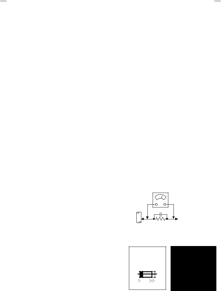
" Alternate Check Method
Plug the AC line cord directly into the AC outlet (do not use a
line isolation transformer during this check.). Use an AC voltmeter having 1000 ohms per volt or more sensitivity in the
following manner. Connect a 1500Ω 10W resistor paralleled by a 0.15μF AC-type capacitor between an exposed metal
part and a known good earth ground (water pipe, etc.). Measure the AC voltage across the resistor with the AC voltmeter. Move the resistor connection to each exposed metal part, particularly any exposed metal part having a return path to
the chassis, and measure the AC voltage across the resistor. Now, reverse the plug in the AC outlet and repeat each measurement. Any voltage measured must not exceed 0.75V AC (r.m.s.). This corresponds to 0.5mA AC (r.m.s.).
However, in tropical area, this must not exceed 0.3V AC (r.m.s.). This corresponds to 0.2mA AC (r.m.s.).
|
AC VOLTMETER |
|
(HAVING 1000 Ω/V, |
GOOD |
OR MOR E SENSITIVITY) |
|
|
EARTH |
|
GR OUND 0.15μF AC-TYPE |
|
|
PLACE THIS PROBE |
|
ON EACH EXPOSED |
1500Ω 10W |
METAL PART |
|
11.High voltage hold down circuit check.
After repair of the high voltage hold down circuit, this circuit shall be checked to operate correctly.
See item "Ho w to check the high voltage hold down circuit".
This mark shows a fast
operating fuse, the letters indicated below
show the rating.
 A
A  V
V
No. 51950 |
3 |

AV-36360 AV-36S36
AV-36330 AV-36S33
AV-36320
FEATURES
"Title TELE-TEXT broadcast of C1, C2, T1, and T2 formula is receivable.
"The voice multiplex function of the MTS system is built in.
"By the EZ SURF function, channel ID and a program name are displayed in the screen automatically [Only for AV-36360 and AV-36S36].
" By the COMPU LINK function, operation interlocked with the DVD deck can be performed from remote control.
"By the three-line digital comb filter, the refreshed image can be seen.
"Two programs can be displayed on the screen by the 2 tuner PIP circuit [Only for AV-36360 and AV-36S36].
"Expression of a favorite screen can be chosen by the VIDEO STATUS function.
"A program can be enjoyed with a powerful sound by the HYPER SURROUND function [Except AV-36320].
"Since the V chip is built in, it can choose, view and listen to a healthy program.
"The RETURN PLUS function is built in.
"A quick favorite program can be looked for by the HYPER-SCAN function.
"Since the component signal input terminal is equipped, it reappears direct without deteriorating the signal from DVD,.
FUNCTIONS
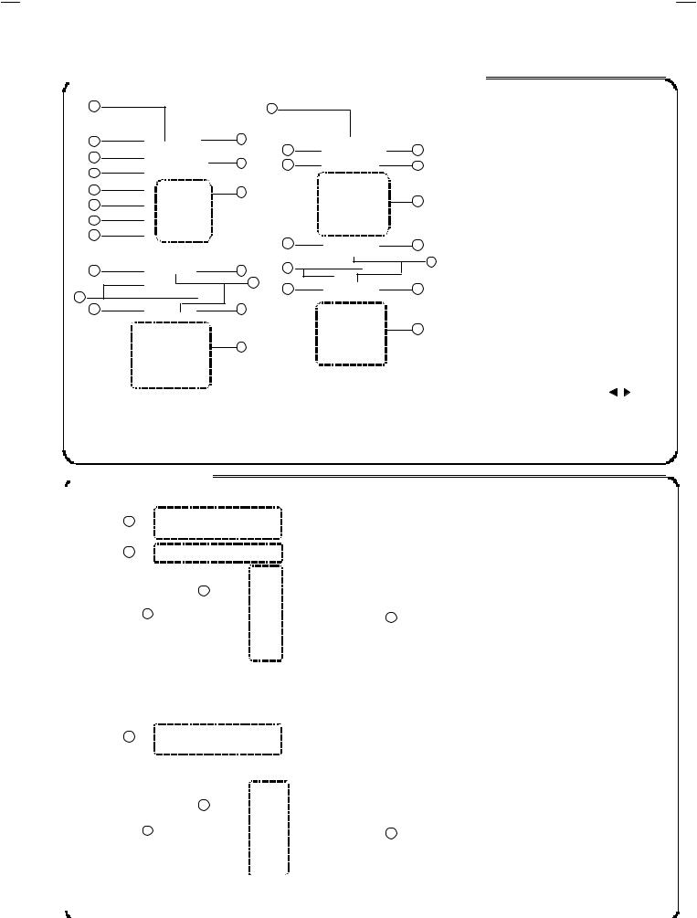
 FRONT PANEL CONTROLS
1 |
2 |
3 |
4 |
5 |
6 |
7
MENU KEY, SELECT ▼ KEY
CHANNEL /+ KEYS OPERATE  /
/  KEYS
KEYS
VOLUME /+ KEY
POWER KEY
ON TIMER / POWER LED
REMOCON WINDOW
|
|
|
AV-36360, 36330, 36S36, 36S33 |
INPUT 3 TERMINAL (V / L / R) |
|
|
|
AV-36320 |
INPUT 2 TERMINAL (V / L / R) |
||
|
|
|
|||
|
|
|
|
|
|
4 |
No. 51950 |
AV-36360 AV-36S36
AV-36330 AV-36S33
AV-36320

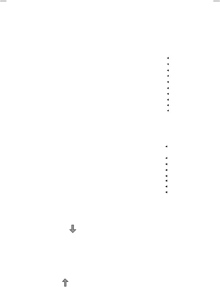
 REMOTE CONTROL UNIT (RM-C254, RM-C255, RM-C205)
1 |
|
|
1 |
2 |
11 |
|
2 |
3 |
|
|
|
12 |
|
3 |
|
4 |
|
||
|
|
|
|
5 |
13 |
|
|
|
|
|
|
6 |
|
|
|
7 |
|
|
|
8 |
|
|
4 |
|
|
|
|
9 |
14 |
|
11 |
|
|
17 |
5 |
16 |
|
|
|
|
|
|
|
10 |
15 |
|
|
|
18 |
|
|
|
|
RM-C254 |
RM-C205 |
FUNCTION |
|
|
|
RM-C255 |
|||
6 |
|
|
------ |
VCR / DVD |
|
|
|
------ |
TV / CATV |
||
7 |
|
||||
|
|
------ |
EZ SURF |
||
|
|
||||
|
|
[Only for RM-C254] |
|||
|
|
|
|
||
8 |
|
|
|
INPUT |
|
|
|
|
DISPLAY |
||
|
|
||||
|
|
|
|
SLEEP TIMER |
|
9 |
|
|
------ |
HYPER SURROUND |
|
|
|
|
|
||
12 |
|
|
VIDEO STATUS |
||
|
|||||
|
|
|
|
||
|
|
|
MUTING |
||
|
|
||||
|
|
|
|
|
|
10 |
|
|
|
MENU |
|
|
|
|
|
||
|
|
|
POWER |
||
|
|
||||
|
|
|
|
|
|
|
|
|
------ |
PIP CONTROL |
|
|
|
[Only for RM-C254] |
|||
13 |
|
|
|
||
|
|
|
CHANNEL NUMBER |
||
|
|
||||
|
|
|
|
|
|
|
|
|
|
V-CHIP |
|
|
|
|
|
|
|
|
|
|
|
EXIT |
|
|
|
|
|
|
|
|
|
|
|
VOLUME -/+ and |
|
|
|
CURSOR / |
|||
|
|
|
|
||
|
|
|
|
CHANNEL +/ and |
|
|
|
CURSOR ▲/▼ |
|||
|
|
|
|
||
|
|
|
|
VCR CONTROL |
[RM-C254, 255] |
[RM-C205] |

 REAR TERMINAL
|
|
1 |
|
|
|
|
|
|
|
|
|
|
|
|
|
|
|
|
|
|
|
|
|
|
|
|
|||
|
|
|
|
|
|
|
|
|
|
|
|
|||
|
2 |
|
4 |
|
|
|
|
|
|
|
|
|||
|
|
|
|
|
|
|
|
|
|
|||||
|
|
|
|
|
|
|
|
|
|
|
|
|
||
|
|
|
|
|
|
|
|
|
|
|
|
|
||
|
3 |
|
|
|
|
|
6 |
AV-36360 |
|
|
|
|||
|
|
|
|
|
|
|
|
|
||||||
|
|
|
|
|
|
|
|
|
|
AV-36S33 |
AV-36320 |
FUNCTION |
|
|
|
|
|
|
|
|
|
|
|
|
|
|
|||
|
|
|
|
|
|
|
|
|
|
|
AV-36330 |
|
||
|
|
|
|
|
|
|
|
|
|
|
|
|
|
|
|
|
|
|
|
|
|
|
|
|
|
AV-36S33 |
|
|
|
|
|
|
|
|
|
|
|
|
|
|
|
|
|
|
|
|
|
|
|
[AV-36360, 36S36, 36330, 36S33] |
|
|
|
|
INPUT 1 |
|
|||
|
|
|
|
|
|
|
S-VIDEO, V, L, R |
|
||||||
|
|
|
|
|
|
|
|
|
|
|||||
|
|
|
|
|
|
|
|
|
|
|
|
|
|
|
|
|
|
|
|
|
|
|
|
|
|
|
------ |
INPUT 2 |
|
|
|
|
|
|
|
|
|
|
|
|
L, R |
|
||
|
|
|
|
|
|
|
|
|
|
|
|
|
|
|
|
1 |
|
|
|
|
|
|
|
|
|
|
|
||
|
|
|
|
|
|
|
|
|
|
AUDIO OUT (FIXED) |
|
|||
|
|
|
|
|
|
|
|
|
||||||
|
|
|
|
|
|
|
|
|
|
|
|
|||
|
|
|
|
|
|
|
|
|
|
|
L, R |
|
||
|
|
|
|
|
|
|
|
|
|
|
|
|
|
|
|
|
|
|
|
|
|
|
|
|
|
|
|
|
|
|
|
|
|
|
|
|
|
|
|
|
|
|
INPUT 2 |
|
|
|
|
|
|
|
|
|
|
|
|
|
------ |
COMPONENT |
|
|
|
|
|
|
5 |
|
|
|
|
|
|
VIDEO or Y, PB, PR |
|
|
|
|
|
|
|
|
|
|
|
|
|
|
|
||
|
|
|
|
|
|
|
|
|
|
|
INPUT 1 |
|
||
|
|
|
|
|
|
|
|
|
|
|
|
|
||
|
3 |
|
|
|
|
|
6 |
------ |
COMPONENT |
|
||||
|
|
|
|
|
|
|
|
VIDEO or Y, PB, PR |
|
|||||
|
|
|
|
|
|
|
|
|
||||||
|
|
|
|
|
|
|
|
|
|
|
|
|
|
|
|
|
|
|
|
|
|
|
|
|
|
|
|
|
|
|
|
|
|
|
|
|
|
|
|
|
|
|
ANTENNA SOCKET |
|
|
|
|
|
|
|
|
|
|
|
|
F-Type |
|
||
|
|
|
|
|
|
|
|
|
|
|
|
|
|
|
|
|
|
|
|
|
|
[AV-36320] |
|
|
|
|
|
|
|
|
|
|
|
|
|
|
|
|
|
|
|
|
||
|
|
|
|
|
|
|
|
|
|
|
|
|
|
|
|
|
|
|
|
|
|
|
|
|
|
|
|
|
|
No. 51950 |
5 |

AV-36360 AV-36S36
AV-36330 AV-36S33
AV-36320
MAIN DIFFERENCE LIST
PARTS NAME |
MODEL |
/M |
/R |
|
ITC TUBE (Inc. DY, P C MAGNET, WEDGE) |
|
A90LLD361X15 |
A90AEJ15X01 |
|
DEG COIL |
|
QQW0106-001 |
CELD067-001JA |
|
|
or QQW0114-001 |
or QQW0136-001 |
||
|
|
|||
MAIN PWB |
|
SGE-1008A-M2 |
SGE-1032A-M2 |
|
CRT SOCKET PWB |
|
SGE-3003A-M2 |
SGE-3011A-M2 |
|
PIP PWB |
|
SGE-4001A-M2 |
|
|
AV SELECTOR PWB |
AV-36360 |
SGE-5002A-M2 |
|
|
E-COAXIAL ASSY |
WJX0014-002A |
|
||
|
|
|||
TERMINAL BOARD |
[BLACK] |
LC20899-006A-A |
|
|
TAP SCREW (for TERM. BOARD) |
|
QYSBSB3010Z (×4) |
|
|
PUSH KNOB |
|
CM35776-B01-H |
|
|
BRAND MARK |
|
CM46084-A01 |
|
|
FRONT CABI. ASSY |
|
CM12747-A0G-MA |
|
|
DOOR |
|
CM36162-005-A |
|
|
REMOCON UNIT |
|
RM-C254-1H |
|
|
ITC TUBE (Inc. DY, P C MAGNET, WEDGE) |
|
A90LLD361X15 |
A90AEJ15X01 |
|
DEG COIL |
|
QQW0106-001 |
CELD067-001JA |
|
|
or QQW0114-001 |
or QQW0136-001 |
||
|
|
|||
MAIN PWB |
|
SGE-1011A-M2 |
SGE-1041A-M2 |
|
CRT SOCKET PWB |
|
SGE-3003A-M2 |
SGE-3011A-M2 |
|
PIP PWB |
|
× |
× |
|
AV SELECTOR PWB |
AV-36330 |
SGE-5002A-M2 |
|
|
E-COAXIAL ASSY |
× |
× |
||
|
||||
TERMINAL BOARD |
[BLACK] |
LC20899-006A-A |
|
|
TAP SCREW (for TERM. BOARD) |
|
QYSBSB3010Z (×4) |
|
|
PUSH KNOB |
|
CM35776-B01-H |
|
|
BRAND MARK |
|
CM46084-A01 |
|
|
FRONT CABI. ASSY |
|
CM12747-A0G-MA |
|
|
DOOR |
|
CM36162-005-A |
|
REMOCON UNIT |
|
RM-C255-1H |
|
|
ITC TUBE (Inc. DY, P C MAGNET, WEDGE) |
|
A90LLD361X15 |
A90AEJ15X01 |
|
DEG COIL |
|
QQW0106-001 |
CELD067-001JA |
|
|
or QQW0114-001 |
or QQW0136-001 |
||
|
|
|||
MAIN PWB |
|
SGE-1014A-M2 |
SGE-1047A-M2 |
|
CRT SOCKET PWB |
|
SGE-3003A-M2 |
SGE-3011A-M2 |
|
PIP PWB |
|
× |
× |
|
AV SELECTOR PWB |
AV-36320 |
SGE-5003A-M2 |
|
|
E-COAXIAL ASSY |
× |
× |
||
|
||||
TERMINAL BOARD |
[BLACK] |
LC20899-007A-A |
|
|
TAP SCREW (for TERM. BOARD) |
|
QYSBSB3010Z (×3) |
|
|
PUSH KNOB |
|
CM35776-B01-H |
|
|
BRAND MARK |
|
CM46084-A01 |
|
|
FRONT CABI. ASSY |
|
CM12747-A0G-MA |
|
|
DOOR |
|
CM36162-005-A |
|
|
REMOCON UNIT |
|
RM-C205-1C |
|
|
6 |
|
No. 51950 |
|
|
|
|
|
|
|
|
|
|
AV-36360 AV-36S36 |
|
|
|
|
|
|
|
|
|
|
AV-36330 AV-36S33 |
|
|
|
|
|
|
|
|
|
|
|
AV-36320 |
|
|
|
|
|
|
|
|
|
|
|
PARTS NAME |
MODEL |
/M |
|
|
|
/R |
|
|||
|
|
|
|
|
|
|
|
|
|
|
ITC TUBE (Inc. DY, P C MAGNET, WEDGE) |
|
A90LLD361X15 |
A90AEJ15X01 |
|
||||||
|
|
|
|
|
|
|
|
|
|
|
DEG COIL |
|
QQW0106-001 |
CELD067-001JA |
|
||||||
|
or QQW0114-001 |
or QQW0136-001 |
|
|||||||
|
|
|
||||||||
MAIN PWB |
|
SGE-1008A-M2 |
SGE-1032A-M2 |
|
||||||
|
|
|
|
|
|
|
|
|
|
|
CRT SOCKET PWB |
|
SGE-3003A-M2 |
SGE-3011A-M2 |
|
||||||
|
|
|
|
|
|
|
|
|
|
|
PIP PWB |
|
SGE-4001A-M2 |
|
|
|
|
|
|
|
|
|
|
|
|
|
|
|
|
|
||
AV SELECTOR PWB |
AV-36S36 |
SGE-5002A-M2 |
|
|
|
|
|
|
|
|
|
|
|
|
|
|
|
|
|||
|
|
|
|
|
|
|
|
|
|
|
E-COAXIAL ASSY |
WJX0014-002A |
|
|
|
|
|
|
|
|
|
|
|
|
|
|
|
|
|
|
||
TERMINAL BOARD |
[SILVER] |
LC20899-006A-A |
|
|
|
|
|
|
|
|
|
|
|
|
|
|
|
|
|||
TAP SCREW (for TERM. BOARD) |
|
QYSBSB3010Z (×4) |
|
|
|
|
|
|
|
|
|
|
|
|
|
|
|
|
|
||
|
|
|
|
|
|
|
|
|
|
|
PUSH KNOB |
|
CM35776-005-H |
|
|
|
|
|
|
|
|
|
|
|
|
|
|
|
|
|
||
|
|
|
|
|
|
|
|
|
|
|
BRAND MARK |
|
CM46084-002 |
|
|
|
|
|
|
|
|
|
|
|
|
|
|
|
|
|
||
|
|
|
|
|
|
|
|
|
|
|
FRONT CABI. ASSY |
|
CM12747-00S-MA |
|
|
|
|
|
|
|
|
|
|
|
|
|
|
|
|
|
||
|
|
|
|
|
|
|
|
|
|
|
DOOR |
|
CM36162-014-A |
|
|
|
|
|
|
|
|
|
|
|
|
|
|
|
|
|
||
|
|
|
|
|
|
|
|
|
|
|
REMOCON UNIT |
|
RM-C254-1H |
|
|
|
|
|
|
|
|
|
|
|
|
|
|
|
|
|
||
|
|
|
|
|
|
|
|
|
|
|
ITC TUBE (Inc. DY, P C MAGNET, WEDGE) |
|
A90LLD361X15 |
A90AEJ15X01 |
|
||||||
DEG COIL |
|
QQW0106-001 |
CELD067-001JA |
|
||||||
|
or QQW0114-001 |
or QQW0136-001 |
|
|||||||
|
|
|
||||||||
MAIN PWB |
|
SGE-1011A-M2 |
SGE-1041A-M2 |
|
||||||
CRT SOCKET PWB |
|
SGE-3003A-M2 |
SGE-3011A-M2 |
|
||||||
PIP PWB |
|
× |
× |
|
|
|
|
|||
AV SELECTOR PWB |
AV-36S33 |
SGE-5002A-M2 |
|
|
|
|
|
|
|
|
|
|
|
|
|
|
|
|
|||
|
|
|
|
|
|
|
|
|
|
|
E-COAXIAL ASSY |
× |
× |
|
|
|
|
||||
|
|
|
|
|
||||||
TERMINAL BOARD |
[SILVER] |
LC20899-006A-A |
|
|
|
|
|
|
|
|
|
|
|
|
|
|
|
|
|||
TAP SCREW (for TERM. BOARD) |
|
QYSBSB3010Z (×4) |
|
|
|
|
|
|
|
|
|
|
|
|
|
|
|
|
|
||
|
|
|
|
|
|
|
|
|
|
|
PUSH KNOB |
|
CM35776-005-H |
|
|
|
|
|
|
|
|
|
|
|
|
|
|
|
|
|
||
BRAND MARK |
|
CM46084-002 |
|
|
|
|
|
|
|
|
|
|
|
|
|
|
|
|
|
||
|
|
|
|
|
|
|
|
|
|
|
FRONT CABI. ASSY |
|
CM12747-00S-MA |
|
|
|
|
|
|
|
|
|
|
|
|
|
|
|
|
|
||
DOOR |
|
CM36162-014-A |
|
|
|
|
|
|
|
|
|
|
|
|
|
|
|
|
|
||
|
|
|
|
|
|
|
|
|
|
|
REMOCON UNIT |
|
RM-C255-1H |
|
|
|
|
|
|
|
|
|
|
|
|
|
|
|
|
|
||
|
|
|
|
|
|
|
|
|
|
|
HOW TO IDENTIFY MODELS
How to recognize from the appearance of the model concerned is written below. Please distinguish from several contents currently printed on the rating label.
|
|
|
|
|
|
|
|
|
|
|
|
|
|
|
Model Name |
|
|
|
|
Model Name |
Detailed Model Number |
||
|
|
|
|
|
|
|
|
|
|
||
|
|
|
|
|
|
|
|
|
|
|
|
|
|
|
|
|
|
|
|
AV-36360 /M |
AV-36360 |
M |
|
|
|
|
|
|
|
|
|
|
|
|
|
|
|
|
|
|
|
|
|
AV-36360 |
/R |
R |
|
|
|
|
|
|
|
|
|
|
|||
|
|
|
|
|
|
|
|
|
|
|
|
|
|
|
|
|
|
|
|
AV-36330 /M |
AV-36330 |
M |
|
|
|
|
|
|
|
|
|
|
|
|
|
|
|
|
|
|
|
|
|
AV-36330 |
/R |
R |
|
|
|
|
|
|
|
|
|
|
|||
|
|
|
|
|
|
|
|
|
|
|
|
|
|
|
|
|
|
|
|
AV-36230 /M |
AV-36320 |
M |
|
|
|
|
|
|
|
|
|
|
|
|
|
|
|
|
|
|
|
|
|
AV-36230 |
/R |
R |
|
|
|
|
|
|
|
|
|
|
|||
|
|
|
|
|
|
|
|
|
|
|
|
|
|
|
|
|
|
|
|
AV-36S36 |
/M |
AV-36S36 |
M |
|
|
|
|
|
|
|
|
|
|
|
|
|
|
|
|
|
|
|
|
AV-36S36 |
/R |
R |
|
|
|
|
|
|
|
|
|
|
|||
|
|
|
|
|
|
|
|
|
|
|
|
|
|
|
|
|
|
|
|
AV-36S33 |
/M |
AV-36S33 |
M |
|
|
|
|
|
|
|
|
|
|
|
|
|
|
|
|
|
|
|
|
AV-36S33 |
/R |
R |
|
|
|
|
|
|
|
|
|
|
|||
|
|
Detailed Model Name |
|
|
|
|
|
||||
|
|
|
|
|
|
|
|
||||
|
|
|
|
|
|
|
|
|
|
|
|
|
|
|
|
|
|
|
|
|
|
|
|
No. 51950 |
7 |

AV-36360 AV-36S36
AV-36330 AV-36S33
AV-36320
SPECIFIC SERVICE INSTRUCTIONS
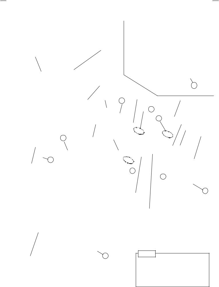
DISASSEMBLY PROCEDURE
REMOVING THE REAR COVER
"Unplug the power plug.
1.As shown in Fig.2, remove the 11 screws marked !.
2.Remove the rear cover toward you.
Note :
When reinstalling the rear cover, carefully push it inward after inserting the chassis into the rear cover groove.
REMOVING THE CHASSIS BASE
"After removing the rear cover.
1.Slightly raise the both sides of the chassis base by hand, and remove the 2 claws marked " (Fig.1 and Fig.2) under the both sides of the chassis from the chassis rail.
2.As shown in Fig.1, draw the chassis base backward along the chassis rail marked #in the arrow direction marked $(Fig.2.). (If necessary, detach the wire clamp, connector’s etc.)
Note :
When conducting a check with power supplied, be sure to confirm that the CRT earth wire is connected to the CRT SOCKET PWB and the MAIN PWB.
REMOVING THE TERMINAL BOARD
"After removing the rear cover.
1.As shown in Fig.2, remove the 4 screws marked%&.
(In case of disassembly the AV-36320, remove the 3 screws marked &.)
2.When you pull out the TERMINAL BOARD, it can be removed.
REMOVING THE FRONT CONTROL PW BOARD
" After removing the rear cover and chassis base .
1.As shown in Fig.2, remove the 2 screws marked 'attached the FRONT CONTROL PWB with the front cabinet.
2.Then remove the FRONT CONTROL PWB.
REMOVING THE FRONT AV IN PW BOARD
" After removing the rear cover and chassis base.
1.Remove the screw marked (at the front input terminal.
2.As shown in Fig.2, pull the claw marked ).
3.Then remove the FRONT AV IN PWB.
REMOVING THE SPEAKER
" After removing the rear cover and chassis base.
1.As shown in Fig.2, r emove the 2 screws marked *.
2.Follow the same steps when removing the other hand speaker.
CHECKING THE MAIN PW BOARD
1.To check the backside of the MAIN PW Board.
(1)Pull out the chassis base. (Refer to REMOVING THE CHASSIS BASE).
(2)Erect the chassis vertically so that you can easily check from the backside of the MAIN PWB.
CAUTION
"When erecting the chassis, be careful so that there will be no contacting with other PWB.
"Before turning on power, make sure that the CRT earth wire and other connectors are properly connected.
WIRE CLAMPING AND CABLE TYING
1.Be sure to clamp the wire.
2.Never remove the cable tie used for tying the wires together.
Should it be inadvertently removed, be sure to tie the wires with a new cable tie.
FRONT CABINET
MAIN PWB
C
CHASSIS BASE
B
Fig. 1
8 |
No. 51950 |
AV-36360 AV-36S36
AV-36330 AV-36S33
AV-36320
CRT
FRONT CABINET
CRT SOCKET PWB |
|
|
FRONT AV IN |
SPEAKER |
PWB |
|
J |
|
CLAW H |
|
CLAW |
|
FRONT CONTROL PWB |
F |
CHASSIS BASE |
|
J
SPEAKER  CLAW B
AV SELECTOR
PWB
G
POWER CORD
B
MAIN PWB
HVT
TERMINAL BOARD
D
E
REAR COVER |
A |
|
PIP PWB
[Only for AV-36360 and AV-36S36]
No te
This illustration describes about AV-36360. Although the other models are slightly different from this illustration, it can use for the other models in the same steps as this illustration.
Fig.2
No. 51950 |
9 |
AV-36360 AV-36S36
AV-36330 AV-36S33
AV-36320
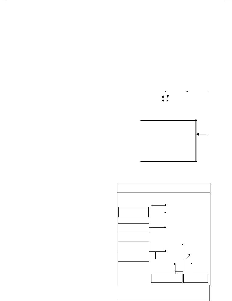
MEMORY IC REPLACEMENT
1. Memory IC
This model uses the memory IC.
This memory IC stores data for proper operation of the video/chroma and deflection circuits. When replacing, be sure to use the IC containing initial setting data.
2.Memory IC replacement procedure
(1)Power off
Switch off the power and disconnect the power plug from the AC outlet.
(2)Replace the memory IC
Be sure to use the memory IC written with the initial setting values.
(3)Power on
Connect the power plug to the AC outlet and switch on the power.
(4) System constant check and setting
Press the SLEEP TIMER key and set SLEEP TIMER for 0 min .
Before disappear the display of SLEEP TIMER settings, simultaneously press the DISPLAY key and VIDEO ST ATUS key of the remote control unit. The SERVICE MENU screen of Fig.1 will be displayed.
While the SERVICE MENU is displayed, select the SYSTEM(SYS) item with CURSOR ▼/▲ key and go into with  /
/ keys. Then the SYSTEM mode screen will be displayed as shown in Fig.2.
Refer to the table of SYSTEM CONSTANT given in page later, and check the each item. If the value is different, select the setting item with the CURSOR ▼/▲ key, and setting with the CURSOR /
/ keys. (The letters of the selected item is displayed in yellow.)
When adjustment has completed, the values store into memory IC automatically.
Press the EXIT key twice to return to the normal screen.
SERVICE MENU
SERVICE MENU |
|
|
|
|
|
|
|
|
|
|
|
|
|
|
|
|
|
||
1.V/C(S) |
2.DEF(D) |
|
|||||||||||||||||
3.SOUND(A) |
4.OTHERS |
|
|||||||||||||||||
5.PIP(PIP) |
6.3L Y/C(LYC) |
|
|||||||||||||||||
7.LOW LIGHT |
8.HIGH LIGHT |
|
|||||||||||||||||
9.RF AFC |
10.VCO |
|
|||||||||||||||||
11.I2C BUS |
12.SYSTEM(SYS) |
|
|
|
|||||||||||||||
|
|
|
|
||||||||||||||||
SELECT BY |
|
|
|
|
|
|
|
|
|
|
|
|
|
|
|
|
|
|
|
|
|
|
|
|
|
|
|
|
|
|
|
|
|
|
|
|
|
|
|
OPERATE BY |
|
|
|
|
|
|
EXIT BY |
EXIT |
|
|
|||||||||
|
|
|
|
|
|
|
|
|
|
|
|
|
|
|
|
|
|
|
|
Fig.1
12. SYSTEM (SYS) MODE
SYS01 VIDEO |
*** |
Fig.2
|
|
|
KEY ASSIGNMENT OF REMOTE CONTROL UNIT |
|
(5) Receiving channel setting |
|
|
|
|
Refer to the OPERATING INSTRUCTIONS and set the receive |
Setting for “0 min” |
|
||
channels (Channels Preset) as described. |
|
|
|
|
(6) User settings |
|
|
|
|
|
|
Simultaneously push |
|
|
Check the user setting items according to the Table 2 given in page |
|
|||
|
|
|||
later. |
|
|
|
|
Where these do not agree, refer to |
the |
OPERAT ING |
|
|
INSTRUCT IONS and set the items as described. |
|
|
|
|
|
|
|
Go into the item |
|
(7) SERVICE MENU setting |
|
|
|
|
Verify what to set in the SERVICE MENU, and set whatever is |
|
|||
necessary (Fig.1). Refer to the SERVICE ADJUSTMENT for setting. |
Setting the value |
|
||
|
|
|
, |
EXIT from |
|
|
|
Select the item |
SYSTEM mode |
|
|
|
Although this illustration of remote control unit is written about |
|
|
|
|
RM-C254 (AV-36360), it can use for operating the other model |
|
|
|
|
of remote control unit as same key assignment. |
|
10 |
No. 51950 |
AV-36360 AV-36S36
AV-36330 AV-36S33
AV-36320
VALUES OF SYSTEM CONSTANT (TABLE 1)
|
|
VARIABLE |
|
|
INITIAL SETTING VALUE |
|
|
||
ITEM |
CONT ENTS |
|
|
|
|
|
|
|
|
RANGE |
AV-36360 |
AV-36S36 |
|
AV-36330 |
|
AV-36S33 |
AV-36320 |
||
|
|
|
|
||||||
|
|
|
|
|
|||||
|
|
|
|
|
|
|
|
|
|
SYS01 |
VIDEO IN |
0 4 |
3 |
3 |
|
3 |
|
3 |
2 |
|
|
|
|
|
|
|
|
|
|
SYS02 |
PIP |
0 1 |
1 |
1 |
|
0 |
|
0 |
0 |
|
|
|
|
|
|
|
|
|
|
SYS03 |
3D Y/C |
0 1 |
0 |
0 |
|
0 |
|
0 |
0 |
|
|
|
|
|
|
|
|
|
|
SYS04 |
Y CV |
0 1 |
0 |
0 |
|
0 |
|
0 |
0 |
|
|
|
|
|
|
|
|
|
|
SYS05 |
CCD PCHK |
0 1 |
1 |
1 |
|
1 |
|
1 |
1 |
|
|
|
|
|
|
|
|
|
|
SYS06 |
PURITY |
0 1 |
0 |
0 |
|
0 |
|
0 |
0 |
|
|
|
|
|
|
|
|
|
|
SYS07 |
VM |
0 1 |
0 |
0 |
|
0 |
|
0 |
0 |
|
|
|
|
|
|
|
|
|
|
SYS08 |
NOISE CR |
0 1 |
0 |
0 |
|
0 |
|
0 |
0 |
|
|
|
|
|
|
|
|
|
|
SYS09 |
CLR TEMP |
0 1 |
0 |
0 |
|
0 |
|
0 |
0 |
|
|
|
|
|
|
|
|
|
|
SYS10 |
THEATER |
0 1 |
0 |
0 |
|
0 |
|
0 |
0 |
|
|
|
|
|
|
|
|
|
|
SYS11 |
THEATER PRO |
0 1 |
0 |
0 |
|
0 |
|
0 |
0 |
|
|
|
|
|
|
|
|
|
|
SYS12 |
BBE |
0 1 |
0 |
0 |
|
0 |
|
0 |
0 |
|
|
|
|
|
|
|
|
|
|
SYS13 |
HYP SURR |
0 1 |
1 |
1 |
|
1 |
|
1 |
0 |
|
|
|
|
|
|
|
|
|
|
SYS14 |
16:9 MD |
0 1 |
0 |
0 |
|
0 |
|
0 |
0 |
|
|
|
|
|
|
|
|
|
|
SYS15 |
HYP SCAN |
0 1 |
1 |
1 |
|
1 |
|
1 |
1 |
|
|
|
|
|
|
|
|
|
|
SYS16 |
EZ SURF |
0 1 |
1 |
1 |
|
0 |
|
0 |
0 |
|
|
|
|
|
|
|
|
|
|
SYS17 |
ID DISP |
0 1 |
1 |
1 |
|
1 |
|
1 |
0 |
|
|
|
|
|
|
|
|
|
|
SYS18 |
COMPULINK |
0 1 |
0 |
0 |
|
0 |
|
0 |
0 |
|
|
|
|
|
|
|
|
|
|
SYS19 |
CCD |
0 1 |
1 |
1 |
|
1 |
|
1 |
1 |
|
|
|
|
|
|
|
|
|
|
SYS20 |
VCHIP |
0 1 |
1 |
1 |
|
1 |
|
1 |
1 |
|
|
|
|
|
|
|
|
|
|
SYS21 |
VCHIP CA |
0 1 |
1 |
1 |
|
1 |
|
1 |
1 |
|
|
|
|
|
|
|
|
|
|
SYS22 |
JVC LOGO |
0 1 |
1 |
1 |
|
1 |
|
1 |
1 |
|
|
|
|
|
|
|
|
|
|
SYS23 |
CMP IN |
0 1 |
1 |
1 |
|
1 |
|
1 |
0 |
|
|
|
|
|
|
|
|
|
|
SYS24 |
CXA1875 |
0 1 |
0 |
0 |
|
0 |
|
0 |
0 |
|
|
|
|
|
|
|
|
|
|
No. 51950 |
11 |
Loading...