


 Loading...
AV-32F703
AV-32F713
AV-32F803
SERVICE MANUAL
COLOR TELEVISION
AV-32F703/Y
AV-32F713/Y
AV-32F803/Y
BASIC CHASSIS
GJ
RM-C326G [RM-C325G]
RM-C326 AV-32F803
AV-32F703
AV-32F713
CONTENTS
!SPECIFICATIONS 2
!SAFETY PRECAUTIONS 3
!FEATURES 4
!HOW TO IDENTIFY MODELS 4
!MAIN DIFFERENCE LIST 5
!FUNCTIONS 6
!SPECIFIC SERVICE INSTRUCTIONS 8
!SERVICE ADJUSTMENTS 12
!PARTS LIST 33
OPERATING INSTRUCTIONS
STANDARD CIRCUIT DIAGRAM 2-1
1 |
COPYRIGHT © 2002 VICTOR COMPANY OF JAPAN, LTD. |
No.52004 |
Jun. 2002
Jun. 2002
AV-32F703
AV-32F713
AV-32F803
SPECIFICATIONS
Items |
|
|
|
|
Contents |
|||
|
|
|
|
|
|
|
||
Dimensions (W×H×D) |
|
|
34-5/8”×27”-5/8”×22-1/4” (877mm×699mm×565mm) |
|||||
Mass |
|
|
140.8 Ibs (64.0 kg) |
|
||||
TV System |
|
TV RF System |
CCIR(M) |
|
||||
and Color System |
|
Color System |
NTSC |
|
||||
|
|
Sound System |
BTSC System (Multi-Channel Sound) |
|
||||
TV Receiving Channels |
|
VL Band |
(02 06) 54MHz 88MHz |
|
||||
and Frequency |
|
VH Band |
(07 13) 174MHz 216MHz |
|
||||
|
|
UHF Band |
(14 69) 470MHz 806MHz |
|
||||
|
|
|
|
|
|
|
||
CATV Receiving Channels |
|
Low Band |
(02 06, A-8) by (02 06&01) |
|
|
|
|
|
and Frequency |
|
High Band |
(07 13) by (07 13) |
|
|
|
||
|
|
Mid Band |
(A 1) by (14 22) |
|
|
|
||
|
|
Super Band |
(J W) by (23 36) |
|
|
(54MHz 804MHz) |
||
|
|
|
|
|||||
|
|
Hyper Band |
(W +1 W+28) by (37 64) |
|
|
|
||
|
|
Ultra Band |
(W +29 W+84) by (65 125) |
|
|
|
||
|
|
Sub Mid Band |
(A8, A4 A1) by (01, 96 99) |
|
|
|
|
|
TV/CATV Total Channel |
180 Channels |
|
||||||
Intermediate Frequency |
Video IF Carrier |
45.75MHz |
|
|||||
|
Sound IF Carrier |
41.25MHz (4.5MHz) |
|
|||||
Color Sub Carrier |
|
|
3.58MHz |
|
||||
Power Input |
|
|
120V AC, 60Hz |
|
||||
Power Consumption |
|
|
160W |
|
||||
Picture Tube |
|
|
32” (80cm) Measured Diagonally |
|
||||
High Voltage |
|
|
31.4kV±1.3kV (at zero beam current) |
|
||||
Speaker |
|
|
2”×4-3/4” (5×12cm) Oval type×2 |
|
||||
Audio Power Output |
|
|
5W + 5W |
|
||||
Input 1 (Rear) |
S-Video |
Y : 1V(p-p) Positive (Negative sync provided, when terminated with 75Ω) |
||||||
|
|
|
C : 0.286V(p-p) (Burst signal, when terminated with 75Ω) |
|||||
|
|
Video |
1V(p-p), 75Ω |
|
||||
|
Audio(L/MONO, R) |
500mV(rms) ( -4dBs ), High Impedance |
||||||
Input 2 (Rear) |
Video |
1Vp-p, 75Ω |
|
|||||
|
Component video |
Y : 1V(p-p) Positive (Negative sync provided, when terminated with 75Ω) |
||||||
Input terminals |
|
|
PB, PR : 0.7V(p-p), 75Ω |
|
||||
Audio(L/MONO, R) |
500mV(rms) ( -4dBs ), High Impedance |
|||||||
|
||||||||
Input 3 (Front) |
Video |
1V(p-p), 75Ω |
|
|||||
|
Audio(L/MONO, R) |
500mV(rms) ( -4dBs ), High Impedance |
||||||
Input 4 (Rear) (For AV-32F8 03) |
|
|
|
|
|
|||
|
Component video |
Y : 1V(p-p) Positive (Negative sync provided, when terminated with 75Ω) |
||||||
|
|
|
PB, PR : 0.7V(p-p), 75Ω |
|
||||
|
Audio(L/MONO, R) |
500mV(rms) ( -4dBs ), High Impedance |
||||||
Fix Audio Output |
|
|
500mV(rms) ( -4dBs ) LOW Impedance (400Hz when modulated 100%) |
|||||
AV compulink Input |
|
|
3.5mm mini jack |
|
||||
Antenna terminal |
|
|
75Ω(VHF/UHF) Terminal, F-T ype Connector |
|||||
Remote Control Unit |
|
|
RM-C326G(AV-32F703) / RM-C326(AV-32F713) /RM-C325G(AV-32F803) |
|||||
|
|
|
(AA/R6/UM-3 battery×2) |
|
||||
|
|
|
|
|
|
|
|
|
Design & specifications are subject to change without notice.
2 |
No.52004 |
AV-32F703
AV-32F713
AV-32F803
SAFETY PRECAUTIONS
1. The design of this product contains special hardware, many circuits and components specially for safety purposes. For continued protection, no changes should be made to the original design unless authorized in writing by the manufacturer.
Replacement parts must be identical to those used in the original circuits. Service should be performed by qualified personnel only.
2.Alterations of the design or circuitry of the products should not
be made. Any design alterations or additions will void the manufacturer's warranty and will further relieve the manufacturer of responsibility for personal injury or property damage resulting therefrom.
3.Many electrical and mechanical parts in the products have special safety-related characteristics. These characteristics are
often not evident from visual inspection nor can the protection afforded by them necessarily be obtained by using replacement components rated for higher voltage, wattage, etc. Replacement parts which have these special safety characteristics are identified in the parts list of Service manual.
Electrical components having such features are identified
by shading on the schematics and by (!) on the parts list in Service manual. The use of a substitute replacement which does not have the same safety characteristics as the recommended replacement part shown in the parts list of Service manual may cause shock, fire, or other hazards.
4. Use isolation transformer when hot chassis.
The chassis and any sub-chassis contained in some products are connected to one side of the AC power line. An isolation transformer of adequate capacity should be inserted between the product and the AC power supply point while performing
any service on some products when the HOT chassis is exposed.
5. Don't short between the LIVE side ground and ISOLATED
(NEUTRAL) side ground or EARTH side ground when repairing.
Some model's power circuit is partly different in the GND. The difference of the GND is shown by the LIVE : (") side GND, the ISOLATED(NEUTRAL) : (#) side GND and EARTH : ($) side GND. Don't short between the LIVE side GND and ISOLATED(NEUTRAL) side GND or EARTH side GND and never measure with a measuring apparatus (oscilloscope etc.)
the LIVE side GND and ISOLATED(NEUTRAL) side GND or EARTH side GND at the same time.
If above note will not be kept, a fuse or any parts will be broken. 6. If any repair has been made to the chassis, it is recommended that the B1 setting should be checked or adjusted (See
ADJUSTMENT OF B1 POWER SUPPLY).
7. The high voltage applied to the picture tube must conform with that specified in Service manual. Excessive high voltage can cause an increase in X-Ray emission, arcing and possible component damage, therefore operation under excessive high
voltage conditions should be kept to a minimum, or should be prevented. If severe arcing occurs, remove the AC power immediately and determine the cause by visual inspection (incorrect installation, cracked or melted high voltage harness, poor soldering, etc.). T o maintain the proper minimum level of
soft X-Ray emission, components in the high voltage circuitry including the picture tube must be the exact replacements or alternatives approved by the manufacturer of the complete product.
8. Do not check high voltage by drawing an arc. Use a high voltage meter or a high voltage probe with a VTVM. Discharge
the picture tube before attempting meter connection, by connecting a clip lead to the ground frame and connecting the other end of the lead through a 10kΩ 2W resistor to the anode
button.
9. When service is required, observe the original lead dress. Extra precaution should be given to assure correct lead dress in the high voltage circuit area. W here a short circuit has occurred, those components that indicate evidence of overheating should be replaced. Always use the
manufacturer's replacement components.
10.Isolation Check
(Safety for Electrical Shock Hazard)
After re-assembling the product, always perform an isolation check on the exposed metal parts of the cabinet (antenna
terminals, video/audio input and output terminals, Control knobs, metal cabinet, screwheads, earphone jack, control shafts, etc.) to be sure the product is safe to operate without danger of electrical shock.
(1)Dielectric Strength Test
The isolation between the AC primary circuit and all metal parts exposed to the user, particularly any exposed metal part having a return path to the chassis should withstand a voltage of 1100V AC (r.m.s.) for a period of one second.
(. . . . Withstand a voltage of 1100V AC (r.m.s.) to an appliance
rated up to 120V, and 3000V AC (r.m.s.) to an appliance rated 200V or more, for a period of one second.)
This method of test requires a test equipment not generally found in the service trade.
(2)Leakage Current Check
Plug the AC line cord directly into the AC outlet (do not use a
line isolation transformer during this check.). Using a "Leakage Current Tester", measure the leakage current from each exposed metal part of the cabinet, particularly any exposed metal part having a return path to the chassis, to a known good earth ground (water pipe, etc.). Any leakage current must not
exceed 0.5mA AC (r.m.s.).
However, in tropical area, this must not exceed 0.2mA AC (r.m.s.).
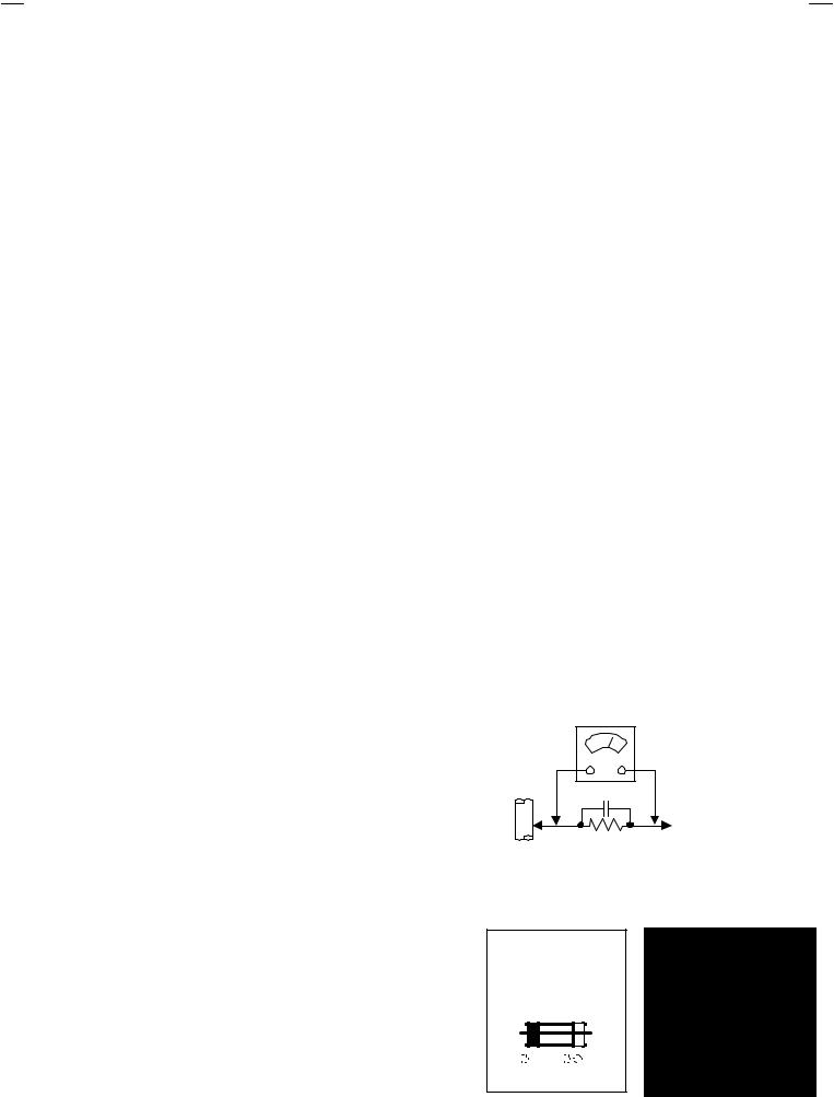
" Alternate Check Method
Plug the AC line cord directly into the AC outlet (do not use a
line isolation transformer during this check.). Use an AC voltmeter having 1000 ohms per volt or more sensitivity in the
following manner. Connect a 1500Ω 10W resistor paralleled by a 0.15μF AC-type capacitor between an exposed metal
part and a known good earth ground (water pipe, etc.). Measure the AC voltage across the resistor with the AC voltmeter. Move the resistor connection to each exposed metal part, particularly any exposed metal part having a return path to
the chassis, and measure the AC voltage across the resistor. Now, reverse the plug in the AC outlet and repeat each measurement. Any voltage measured must not exceed 0.75V AC (r.m.s.). This corresponds to 0.5mA AC (r.m.s.).
However, in tropical area, this must not exceed 0.3V AC (r.m.s.). This corresponds to 0.2mA AC (r.m.s.).
|
AC VOLTMETER |
|
(HAVING 1000 Ω/V, |
GOOD |
OR MOR E SENSITIVITY) |
|
|
EARTH |
|
GR OUND 0.15μF AC-TYPE |
|
|
PLACE THIS PROBE |
|
ON EACH EXPOSED |
1500Ω 10W |
METAL PART |
|
11.High voltage hold down circuit check.
After repair of the high voltage hold down circuit, this circuit shall be checked to operate correctly.
See item "How to check the high voltage hold down circuit".
This mark shows a fast
operating fuse, the letters indicated below
show the rating.
 A
A  V
V
No. 52004 |
3 |
AV-32F703
AV-32F713
AV-32F803
FEATURES
•New chassis design enables use of a single board with simplified circuitry.
•Users can make fun to connect the DVD player with the component video signal input terminal.
•Provided with miniature tuner (TV/CATV).
•Multifunctional remote control permits picture adjustment.
•Adoption of the CHANNEL GUARD function prevents the specific channels from being selected, unless the “ID number” is key in.
•I2C bus control utilizes single chip ICs.
•Adoption of the VIDEO STATUS / THEATER PRO. function.
•Adoption of the ON/OFF TIMER and SLEEP TIMER function.
•Built-in V-CHIP system.
•Closed-caption broadcasts can be viewed.
•Built-in MTS system, BBE / HYPER-SURROUND system.
•S-VIDEO input terminal for taking best advantage of Super VHS.
•Digital Comb filter Improved picture quality.
•Built-in EZ SURF system.(AV-32F803)
By pushing the EZ SURF key, the counterprogram information can be displayed in the text form that is obtained from the three program information: the CALL LETTER (broadcasting station ID), network names and program names in the XDS data. W hen the PIP function is turned on, the counterprograms will be displayed on the PIP one by one while the text on the main screen is displayed simultaneously.
HOW TO IDENTIFY MODELS
How to recognize from the appearance of the model concerned is written below. Please distinguish from several contents currently printed on the rating label.
[RATING LABEL]
Indicated Basic Model Name
AV-32F703
AV-32F713
AV-32F803
Indicated “Y” letter as model attribute name.
4 |
No.52004 |
AV-32F703
AV-32F713
AV-32F803
MAIN DIFFERENCE LIST
Model name |
AV-32F803/Y |
AV-32F703/Y |
AV-32F713/Y |
! |
|||
Parts Name |
|
|
|
MAIN PWB |
SGJ -1010A-M2 |
SGJ -1012A-M2 |
SGJ -1011A-M2 |
PIP PWB |
SGJ -4001A-M2 |
× |
× |
AV SEL PWB |
SGJ -5001A-M2 |
SGJ -5002A-M2 |
← |
3D Y/C SEP MODULE PWB |
SGJ0Y001A-M2 |
× |
× |
! FRONT CABI. ASSY |
LC11048-003B-A (Silver) |
← |
LC11048-004A-A (Black) |
JVC MARK |
CM48006-008-C |
← |
CM48006-009-C |
! DOOR |
LC20628-001C-A |
← |
LC20628-002A-A |
! KNOB (POWER) |
LC31237-001A-A |
← |
LC31237-002A-A |
OPERATION SHEET |
LC31238-004A-A |
← |
LC31238-005A-A |
! CONTROL KNOB |
LC20217-004B-A |
← |
LC20217-006A-A |
! TERMINAL BOARD |
LC20899-005A-A |
LC20899-004A-A |
← |
REMOCON UNIT |
RM-C325G-1A |
RM-C326G-1A |
RM-C326-1A |
Comb filter |
3D Y/C separate comb filter |
3 line digital comb filter |
← |
Picture in Picture |
2 Tuner PIP |
NO |
← |
EZ Surf |
YES |
NO |
← |
Input Terminal |
Input1 Input4 |
Input1 Input3 |
← |
No.52004 |
5 |
AV-32F703
AV-32F713
AV-32F803
FUNCTIONS
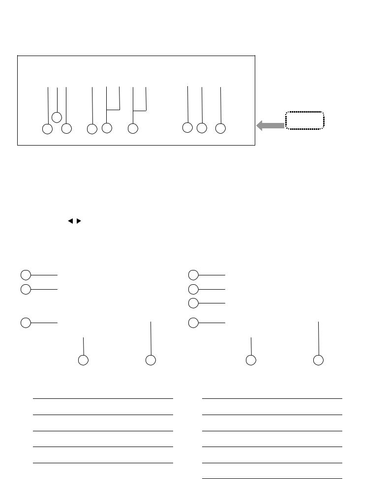
FRONT PANEL CONTROL
2
1 |
3 |
4 |
5 |
6 |
7 |
8 |
9 |
|
1INPUT3 VIDEO terminal |
6VOLUME -/+ buttons |
|
|
|
|
2INPUT3 AUDIO L/MONO terminal |
7SENSOR, REMOTE CONTROL |
|
|
|
|
3INPUT3 AUDIO R terminal |
8ON TIMER LED |
|
|
|
|
4MENU button (▼) |
9POWER button |
|
|
|
|
5CHANNEL -/+ buttons |
|
|
OPERATE / buttons (use MENU screen) |
|
REAR TERMINAL |
|
|
|
[ AV-32F703/Y, AV-32F713/Y ] |
[ AV-32F803/Y ] |
1 |
1 |
|
2 |
2 |
|
|
|
3 |
3 |
4 |
|
4 |
5 |
5 |
6 |
|
[ AV-32F703/Y, AV-32F713/Y ] |
|
|
[ AV-32F803/Y ] |
|
|
|
|
|
|
1INPUT 1 (S-VIDEO, V, L/MONO, R) terminals
2INPUT 2 (V, L/MONO, R) terminals
/ COMPONENT VIDEO(Y, PB, PR) terminals
3AUDIO OUT(L, R) terminals
4AV COMPULINK
5VHF / UHF terminal
1INPUT 1 (S-VIDEO, V, L/MONO, R) terminals
2INPUT 2 (V, L / MONO, R) terminals
/ COMPONENT VIDEO(Y, PB, PR) terminals
3INPUT 4 (L, R) terminals
/ COMPONENT VIDEO(Y, PB, PR) terminals
4AUDIO OUT(L, R) terminals
5AV COMPULINK
6VHF / UHF terminal
6 |
No.52004 |

REMOTE CONTROL UNIT
RM-C326G : AV-32F703/Y RM-C326 : AV-32F713/Y
1 2 3 4
5
6
7
8
9
10
11
12
13
14
[RM-C325G : AV-32F803/Y]
1 2 3 4
23
5
6
7
8
9
10
11
12
13
14
AV-32F703
AV-32F713
AV-32F803
1TV / CATV switch
2VCR / DVD switch
316 : 9 MODE Key
4POWER Key
5INPUT Key (  TV
TV  VIDEO1
  VIDEO2
  VIDEO3
  )
)
6DISPLAY key
7SLEEP TIMER Key (  0
0  15
15  30 ……165
  180
180  )
)
8HYPER SUR. Key
159VIDEO STATUS Key ATHEATER PRO key
|
17 BBBE key |
18 |
CMUTING Key |
|
16 DFUNCTION Key ( CH -/+ / VOL -/+ )
19The FUNCTION keys operate the CHANNEL and VOLUME normally. These keys also operate the MENU system.
20
EMENU Key
FNUMBERS Key
G100+ Key
21HRETURN+ Key ILIGHT Key JV-CHIP Key KEXIT Key LVCR / DVD Keys
1TV / CATV switch
2VCR / DVD switch
316 : 9 MODE Key
4POWER Key
225INPUT Key (  TV
TV  VIDEO1
  VIDEO2
  VIDEO3
  VIDEO4
  )
)
6DISPLAY key
15 |
7SLEEP TIMER Key ( |
|
0 |
|
15 |
|
30 ……165 |
|
180 |
|
) |
|
|
|
|
|
|||||||
|
|
|
|
|
|
|
|
|
|||
16 |
8HYPER SUR. Key |
||||||||||
|
|||||||||||
|
|
|
|
|
|
|
|
|
|
|
|
17 |
9VIDEO STATUS Key |
||||||||||
18ATHEATER PRO key BBBE key
19CMUTING Key
DFUNCTION Key ( CH -/+ / VOL -/+ )
20The FUNCTION keys operate the CHANNEL and VOLUME normally. These keys also operate the MENU system.
EMENU Key
21FNUMBERS Key G100+ Key HRETURN+ Key ILIGHT Key JV-CHIP Key KEXIT / PIP OFF Key LVCR / DVD Keys MPIP Key
NEZ SURF Key (Back Program Information can be displayed.)
No.52004 |
7 |

AV-32F703
AV-32F713
AV-32F803
SPECIFIC SERVICE INSTRUCTIONS
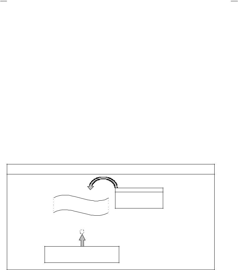
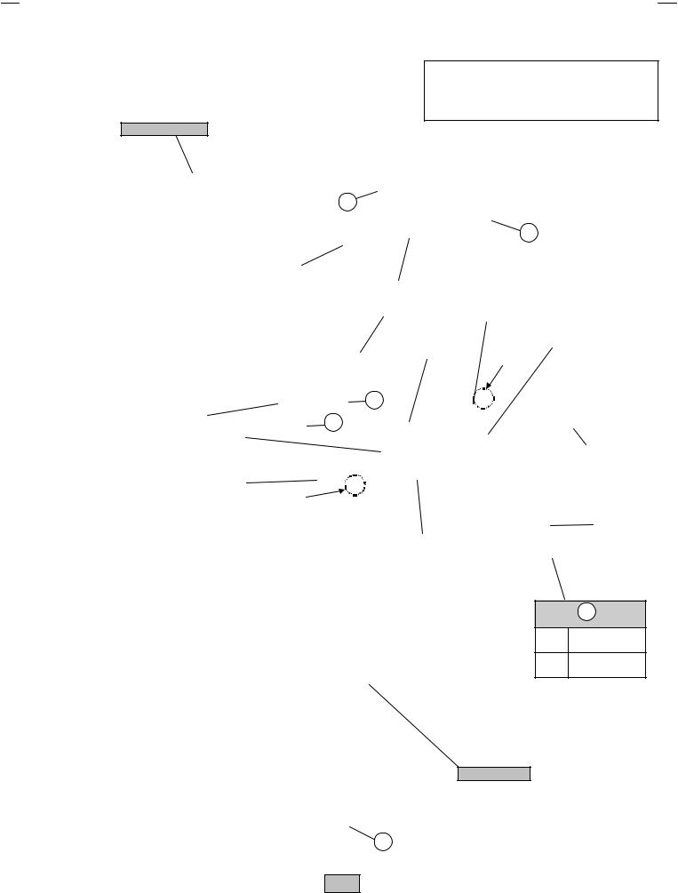
DISASSEMBLY PROCEDURE
REMOVING THE REAR COVER
1.Disconnect the power plug from AC outlet.
2.As shown in the Fig.1, remove the 12 screws marked !.
3.Withdraw the rear cover backward.
CHECKING THE CHASSIS
To check the PW Board from back side.
1.Pull out the chassis (refer to REMOVING THE CHASSIS).
2.Erect the chassis vertically so that you can easily check the back side of the PW Board.
REMOVING THE TERMINAL BOARD
" After removing the rear cover.
1.As shown in Fig.1, remove the screws marked ".
2.Withdraw the terminal board toward you.
REMOVING THE CHASSIS
" After removing the rear cover and terminal board.
1.Slightly raise the both sides of chassis by hand and remove the 2 claws under the both side of the chassis from the front cabinet.
2.Withdraw the chassis backward.
(If necessary, remove the wire clamp, connectors etc.)
REMOVING THE SPEAKER
"After removing the rear cover.
1.As shown in Fig. 1, removing the 2 screws marked #, then remove the speaker with the speaker holder
2.Then remove the 2 screws marked $%to detach the speaker from speaker holder.
3.Follow the same steps when removing the other hand speaker.
NOTE : When removing the 2 screws marked # of the speaker,
remove the lower side screw first, and then remove the upper one.
[CAUTION]
"When erecting the chassis, be careful so that there will be no contacting with other PW Board.
"Before turning on power, make sure that the wire connector is properly connected.
"When conducting a check with power supplied, be sure to confirm that the CRT EARTH WIRE (BRAIDED ASS’Y) is connected to the CRT SOCKET PW board.
WIRE CLAMPING AND CABLE TYING
1.Be sure to clamp the wire.
2.Never remove the cable tie used for tying the wires together. Should it be inadvertently removed, be sure to tie the wires with a new cable tie.
REMOVING THE LED & POWER SW PWB
" After removing the rear cover and terminal board.
1.Remove the 2 screws marked &as shown in Fig.1.
2.Withdraw the LED & POWER SW PWB toward you. * If necessary, remove the wire clamp, connector etc.
REMOVING THE FRONT CONTROL PWB
" After removing the rear cover & terminal board.
1.Remove the 2 screws marked 'as shown in Fig.1.
2.Withdraw the FRONT CONTROL PWB toward you. * If necessary, remove the wire clamp, connector etc.
8 |
No.52004 |
AV-32F703
AV-32F713
AV-32F803
This illustration describes about the AV-32F803/Y. When disassembling the AV-32F703/Y and AV32F713/Y, you can use this illustration as same steps as AV-32F803/Y.
FRONT CABINET
D
|
|
|
|
|
|
|
|
|
|
|
|
|
|
|
|
|
|
C |
|
|||
|
|
|
|
|
|
|
CRT |
|
|
|
|
|
|
|||||||||
|
|
|
|
|
|
|
|
|
|
|
|
|
|
|
|
|
|
|
|
|||
|
|
|
|
|
|
|
SOCKET |
|
|
|
|
|
|
|
|
|
|
|
|
|
||
|
|
|
|
|
|
|
PWB |
|
|
|
|
|
|
|
|
|
|
|
|
|
||
|
|
|
|
|
|
|
|
|
|
|
|
|
|
|
|
|
|
|
|
|
|
|
|
|
|
|
|
|
|
|
SPEAKER |
|
|
|
|
|
|
|
|
|
|
||||
|
|
|
|
|
|
|
|
|
|
|
|
|
|
|
|
|
|
|
|
|
||
|
|
|
|
|
|
|
|
|
FRONT CONTROL |
|
|
|
|
|
|
|
|
|
||||
|
|
|
|
|
|
|
|
|
|
DAF PWB |
|
|
|
|
|
|
||||||
|
|
|
|
|
|
|
|
|
|
|
|
PWB |
|
|
|
|||||||
|
|
|
|
|
|
|
|
|
|
|
|
|
|
|
|
|
|
|
|
|
|
|
|
|
|
|
|
|
|
|
|
|
|
|
PIP PWB |
|
|
|
|
|
MAIN PWB |
|
|
||
|
|
|
|
|
|
|
|
|
|
|
|
AV-32F803 |
/Y |
|
|
|
|
|
|
|
|
|
|
|
|
|
|
|
|
|
|
|
|
CLAW |
|
|
|
|
|
||||||
|
|
|
|
|
|
|
|
|
F |
|
|
|
|
|
|
|
|
|
||||
|
|
|
|
|
|
|
|
|
|
|
|
|
|
|
|
|
|
|||||
LED & POWER SW PWB |
|
|
|
E |
|
|
|
|
|
|
|
|
|
|||||||||
|
|
|
|
|
|
|
|
|
|
|
|
|
|
|
||||||||
|
|
|
|
|
|
|
|
|
|
|
|
|
|
|
|
|
|
|
|
|
||
|
3D Y/C SEP MODULE PWB |
|
|
|
|
|
|
|
|
|
|
|
|
|
|
|
|
|
|
|
||
|
AV-32F803/Y |
|
|
|
|
|
|
|
|
|
|
|
|
|
|
|
|
|
|
|
||
|
|
|
|
|
|
|
|
|
|
|
|
|
|
|
|
|
POWER CORD |
|
||||
|
|
|
|
|
|
|
|
|
|
|
|
|
|
|
|
|
|
|
|
|
|
|
|
|
CHASSIS BASE |
|
|
|
|
|
|
|
|
|
|
|
|
|
|
|
|
|
|
|
|
|
|
|
|
|
CLAW |
|
|
|
|
|
|
|
|
|
|
|||||||
|
|
|
|
|
|
|
|
|
|
|
|
|
|
|
|
|
|
|
|
|
|
|
|
|
|
|
|
|
|
|
|
|
|
|
|
|
|
|
|
|
|
|
|
TERMINAL |
|
|
|
|
|
|
|
|
|
|
|
|
|
|
|
|
|
|
|
|
|
|
BOARD |
|
|
|
|
|
|
|
|
|
|
|
|
|
AV SEL PWB |
|
|
|
|
|
|
|
|||
|
|
|
|
|
|
|
|
|
|
|
|
|
|
|
|
|
|
|
|
|
|
|
B
(×6) AV-32F803/Y
(×4) AV-32F703/Y
AV-32F713/Y
REAR COVER
A
Fig.1
No.52004 |
9 |
AV-32F703
AV-32F713
AV-32F803
MEMORY IC REPLACEMENT
1. Memory IC
This TV uses memory IC.
This memory IC stores data for proper operation of the video and deflection circuits. When replacing the memory IC, be sure to use an IC containing this (initial value) data.
2.Memory IC replacement procedure
(1)Power off
Switch off the power and disconnect the power plug from the AC outlet.
(2)Replace the memory IC
Be sure to use a memory IC written with the initial setting data.
(3)Power on
Connect the power plug to the AC outlet and switch on the power.
(4)Confirm the system constant value
"Normally,do not adjust the 12.SYSTEM (SYS).
"When adjust, be sure to input the signal.
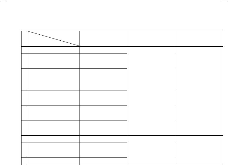
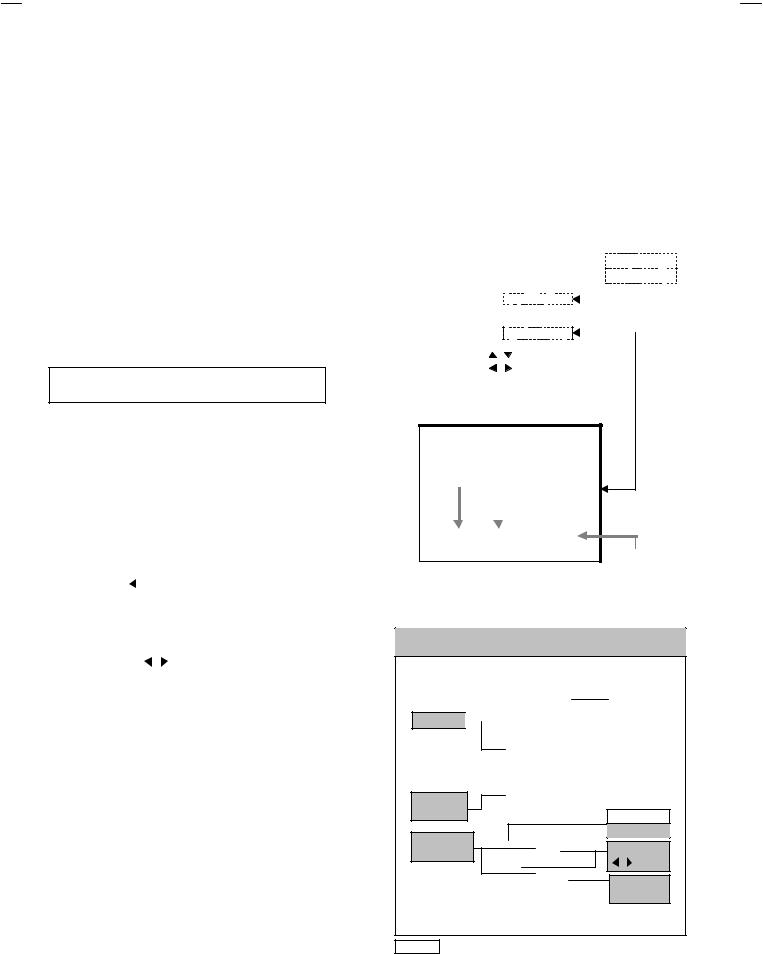
How to enter the SERVICE MENU.
1)Press the SLEEP TIMER key of the remote control unit and set the SLEEP TIMER for 0 min .
2)Before disappear the display of SLEEP TIMER settings, simultaneously press the DISPLAY key and VIDEO STATUS key of the remote control unit.
3)The SERVICE MENU screen will be displayed as shown Fig.1.
How to enter the 12. SYSTEM(SYS).
4)While the SERVICE MENU is displayed, select the 12.SYSTEM(SYS) item with FUNCTION (▼/▲) keys, and the FUNCTION ( / ) keys is pressed, the screen will be displayed as shown in Fig.2.
5)Refer to the SYSTEM ( SYSTEM CONSTANT) TABLE 1 and check the setting items. If the value is different, select the setting item with the FUNCTION (▼/▲) keys and adjust the setting with
the FUNCTION( / ) keys. (The letters of the selected item are displayed in yellow.)
6)When adjustment has completed, the values store into memory IC automatically
7)Press the EXIT key to return the SERVICE MENU screen.
8)Then press the EXIT key again to return the normal screen.
(5)Receive the channel setting
Refer to the OPERATING INSTRUCTIONS (USER'S GUIDE) and set the receive channels (Channels Preset) as described.
(6)User settings
Check the user setting items according to TABLE 2.
Where these do not agree, refer to the OPERATING INSTRUCT IONS (USER'S GUIDE) and set the items as described.
(7)SERVICE MENU setting
Verify what to set in the SERVICE MENU, and set whatever is necessary (Fig.1) .
Refer to the SERVICE ADJUSTMENT for setting.
SERVICE MENU
|
|
|
|
|
|
|
|
|
|
|
|
SERVICE MENU |
|
|
|
|
|
AV-32F803/Y |
|||
|
1.V/C(S) |
2.DEF(D) |
|
|
|
6.3D Y/C(DYC) |
||||
|
3.SOUND(A) |
4.OTHERS(F) |
|
|
|
|
|
|
||
|
5.PIP(PIP) |
6.3L Y/C(LYC) |
|
|
|
|
|
|
||
|
|
|
|
|
|
|
||||
|
7.LOW LIGHT |
8.HIGH LIGHT |
|
|
|
|
|
|
||
|
9.RF AFC |
10.VCO |
|
|
|
|
|
|
||
|
11.I2C BUS |
12.SYSTEM(SYS) |
|
|
|
|
|
|
||
|
|
|
|
|
|
|
||||
|
SELECT BY |
|
|
|
|
|
|
|
|
|
|
|
|
|
|
|
|
|
|
|
|
|
OPERATE BY |
|
|
EXIT BY |
EXIT |
|
|
|
|
|
|
|
|
|
|
|
|
|
|
|
|
Fig.1
12.SYSTEM(SYS)
SETTING ITEM NUMBER
SETTING ITEM
|
|
|
SYS01 VIDEO IN |
*** |
|
SETTING VALUE
Fig.2
KEY ASSIGNMENT OF REMOTE CONTROL UNIT
(RM-C325G)
POWER
DISPLAY 
SLEEP |
|
|
|
NUMBER |
|
||||
|
|
|||
TIMER |
|
|
|
|
VIDEO |
|
|
|
|
|
|
STATUS |
|
|
|
|
MUTING |
|
|
|
|
|
|
|
|
FUNCTION |
|
|
|
|
MEMORY |
|
|
|
|
|
FUNCTION |
||
▼/▲ |
|
|
|
|
||
|
|
|
|
/ |
|
|
|
|
|
|
|
|
|
|
|
|
|
|
EXIT |
|
|
|
|
|
|
PIP OFF |
|
NOTE Although |
design |
is |
different |
as |
this figure, |
each |
remote controller has the same control function.
10 |
No. 52004 |
Loading...