


 Loading...
AV28T25EKS
AV28T25EKB
AV28T55EKS
AV28T25EIS
SERVICE MANUAL
COLOUR TELEVISION
AV28T25EKS
AV28T25EKB
AV28T55EKS
AV28T25EIS
BASIC CHASSIS
JL
CONTENTS
!SPECIFICATIONS 2
!SAFETY PRECAUTIONS 4
!WARNING 4
!FEATURES 5
!MAIN DIFFERENCE LIST 5
!SPECIFIC SERVICE INSTRUCTIONS 6
!SERVICE ADJUSTMENTS 12
!PARTS LIST 29
STANDARD CIRCUIT DIAGRAM 2-1
1 |
COPYRIGHT © 2002 VICTOR COMPANY OF JAPAN, LTD. |
No.51942 |
|
|
Apr. 2002 |

AV28T25EKS
AV28T25EKB
AV28T55EKS
AV28T25EIS
SPECIFICATIONS
Item |
|
|
|
|
|
|
Content |
|
|
|
|
|
|
|
|
|
|
|
|
|
|
AV28T25EKS / AV28T 25EKB / AV28T55EKS |
|
AV28T25EIS |
||
|
|
|
|
|
|
|
||
Dimensions ( W×H×D ) |
|
854mm×507.5mm×493.5mm |
|
|
||||
Mass |
|
|
43.0kg |
|
|
|
|
|
|
|
|
|
|
|
|
|
|
TV RF System |
|
|
CCIR ( I ) |
|
|
|
|
|
Colour System |
|
|
PAL |
|
|
|
|
|
|
|
|
NTSC (Only in EXT mode) |
|
|
|||
Stereo System |
|
|
NICAM |
|
|
|
|
|
Teletext System |
|
|
FLOF (Fastext) |
|
|
|
|
|
|
|
|
WST(Standard system) |
|
|
|||
|
|
|
|
|
|
|
|
|
Receiving Frequency |
|
|
|
|
|
|
|
|
|
VHF |
|
|
|
|
|
|
47MHz 470MHz |
|
|
|
|
|
|
|
||
|
UHF |
|
470MHz 862MHz |
|
470MHz 862MHz |
|||
Intermediate Frequency |
|
|
|
|
|
|
|
|
|
|
|
|
|
|
|
||
|
VIF Carrier |
|
38.9MHz ( I ) |
|
|
|
|
|
|
SIF Carrier |
|
32.9MHz ( 6.0MHz:I ) |
|
|
|||
Colour Sub Carrier Freq. |
|
|
|
|
|
|
|
|
|
PAL |
|
4.43MHz |
|
|
|
|
|
|
NT SC |
|
3.58MHz / 4.43MHz |
|
|
|||
|
|
|
|
|||||
|
|
|
|
|
|
|
|
|
Power Input |
|
|
AC 220V 240V , 50Hz |
|
|
|||
Power Consumption |
|
180W(Max) / 120W(Avg) |
|
|
||||
|
|
|
Standby : 3W |
|
|
|
|
|
Aerial Input Term |
|
75Ωunbalanced, Coaxial |
|
|
||||
|
|
|
|
|
|
|
|
|
Picture Tube |
|
|
Visible size : 66cm, Measured diagonally |
|
|
|||
|
|
|
|
+1kV |
|
|
|
|
High Voltage |
|
|
31.0kV -1. 5kV |
(at zero beam current) |
|
|
||
Speaker |
|
|
6.5cm×13cm Oval type×2 |
|
|
|||
Au dio Output |
|
|
10W + 10W |
|
|
|
|
|
|
|
|
|
|
|
|
||
EXT-1/EXT-2/EXT-3 |
|
21-pin Euro connector |
|
|
||||
(Input / Output) |
|
|
(SCART socket) |
|
|
|||
|
|
|
|
|
|
|
|
|
EXT-4 (Input) |
Video |
|
1Vp-p 75Ω(RCA pin jack) |
|
|
|||
|
Au dio (L/R) |
|
500mVrms( -4dBs ), High Impedance ( RCA pin jack ) |
|||||
|
S / Video |
|
Y : 1Vp-p POSITIVE (Negative sync Provided, when terminated with 75Ω) |
|||||
|
|
|
C : 0.286Vp-p (Burst signal, when terminated with 75Ω) |
|||||
AUDIO OUT (Variable) |
|
0 1Vrms, Low Impedance (RCA pin jack×2) |
|
|
||||
Headphone jack |
|
|
Stereo mini jack (φ3.5mm ) |
|
|
|||
|
|
|
|
|
|
|
|
|
|
|
|
RM-C55H-1C(AV28T25EKS/AV28T55EKS) |
|
|
|||
|
|
|
(AAA/R03 dry battery ×2) |
|
|
|||
Remote Control Unit |
|
RM-C51-1C (AV28T25EKB) |
|
RM-C55H-1C (AAA/R03 dry battery×2) |
||||
|
|
|
|
|
||||
|
|
|
(AAA/R03 dry battery ×2) |
|
|
|||
|
|
|
|
|
|
|
|
|
Design & specifications are subject to change without notice.
2 |
No.51942 |

AV28T25EKS
AV28T25EKB
AV28T55EKS
AV28T25EIS
■21-pin Euro connector (SCART socket) : EXT-1 / EXT-2 / EXT-3
(P-P= Peak to Peak, S-W= Sync tip to white peak, B-W= Blanking to white peak)
Pin |
Signal Designation |
Matching Value |
EXT-1 |
EXT-2 |
EXT-3 |
|
No . |
||||||
|
|
|
|
|
||
|
|
|
|
|
|
|
|
|
|
|
|
|
|
1 |
AUDIO R output |
500mVrms(Nominal), |
○ |
○ |
NC |
|
|
|
Low impedance |
(TV OUT) |
(LINE OUT) |
||
|
|
|
||||
|
|
|
|
|||
|
|
|
|
|
|
|
2 |
AUDIO R input |
500mVrms(Nominal), |
○ |
○ |
○ |
|
|
|
High impedance |
||||
|
|
|
|
|
||
|
|
|
|
|
|
|
3 |
AUDIO L output |
500mVrms(Nominal), |
○ |
○ |
NC |
|
|
|
Low impedance |
(TV OUT) |
(LINE OUT) |
||
|
|
|
||||
|
|
|
|
|||
|
|
|
|
|
|
|
4 |
AUDIO GND |
|
○ |
○ |
○ |
|
|
|
|
|
|
|
|
5 |
GND (B) |
|
○ |
○ |
○ |
|
|
|
|
|
|
|
|
6 |
AUDIO L input |
500mVrms(Nominal), |
○ |
○ |
○ |
|
|
|
High impedance |
||||
|
|
|
|
|
||
|
|
|
|
|
|
|
7 |
B input |
700mVB-W, 75Ω |
○ |
NC |
NC |
|
|
|
|
|
|
|
|
8 |
FUNCTON SW |
Low : 0-3V, High : 8-12V, High |
○ |
○ |
○ |
|
|
(SLOW SW) |
impedance |
|
|
|
|
|
|
|
|
|
|
|
9 |
GND (G) |
|
○ |
○ |
○ |
|
|
|
|
|
|
|
|
10 |
SCL3 |
|
NC |
○ |
NC |
|
|
|
|
|
|
|
|
11 |
G input |
700mVB-W, 75Ω |
○ |
NC |
NC |
|
|
|
|
|
|
|
|
12 |
SDA3 |
|
NC |
○ |
NC |
|
|
|
|
|
|
|
|
13 |
GND (R) |
|
○ |
○ |
○ |
|
|
|
|
|
|
|
|
14 |
GND (YS ) |
|
○ |
NC |
NC |
|
|
|
|
|
|
|
|
15 |
R / C input |
R : 700mVB -W, 75Ω |
○ |
○ |
○ |
|
|
|
C : 300mVP-P , 75Ω |
(only R) |
(only C) |
(only C) |
|
|
|
|
|
|
|
|
16 |
Ys input |
Low : 0 - 0.4, High : 1 - 3V, 75Ω |
○ |
NC |
NC |
|
|
|
|
|
|
|
|
17 |
GND(VIDEO output) |
|
○ |
○ |
○ |
|
|
|
|
|
|
|
|
18 |
GND(VIDEO input) |
|
○ |
○ |
○ |
|
|
|
|
|
|
|
|
19 |
VIDEO output |
1VP-P(Negative going sync), 75Ω |
○ |
○ |
NC |
|
|
|
|
(TV) |
(LINE OUT) |
||
|
|
|
|
|||
|
|
|
|
|
|
|
20 |
VIDEO / Y input |
1VP-P(Negative going sync), 75Ω |
○ |
○ |
○ |
|
|
|
|
|
|
|
|
21 |
COMMON GND |
|
○ |
○ |
○ |
|
|
|
|
|
|
|
[Pin assignment]
No.51942 |
3 |

AV28T25EKS
AV28T25EKB
AV28T55EKS
AV28T25EIS
SAFETY PRECAUTIONS
1.The design of this product contains special hardware and many circuits and components specially for safety purposes. For continued protection, no changes should be made to the original design unless authorized in writing by the manufacturer. Replacement parts must be identical to those used in the original circuits. Service should be performed by qualified personnel only.
2.Alterations of the design or circuitry of the product should not be made. Any design alterations or additions will void the manufacturer's warranty and will further relieve the manufacturer of responsibility for personal injury or property damage resulting therefrom.
3.Many electrical and mechanical parts in the product have special safety-related characteristics. These characteristics are often not evident from visual inspection nor can the protection afforded by them necessary be obtained by using replacement components rated for higher voltage, wattage, etc. Replacement parts which
have these special safety characteristics are identified in the Parts List of Service Manual. Electrical components having such features are identified by shading on the schematics and by (!) on the Parts List in the Service Manual. The use of a substitute replacement which does not have the same safety characteristics as the recommended replacement part shown in the Parts List of Service Manual may cause shock, fire, or other hazards.
4.The leads in the products are routed and dressed with ties, clamps, tubing’s, barriers and the like to be separated from live parts, high temperature parts, moving parts and / or sharp edges for the prevention of electric shock and fire hazard. When service is required, the original lead routing and dress should be observed, and it should be confirmed that they have been returned to normal, after re-assembling.
WARNING
1.The equipment has been designed and manufactured to meet international safety standards.
2.It is the legal responsibility of the repairer to ensure that these safety standards are maintained.
3.Repairs must be made in accordance with the relevant safety standards .
4.It is essential that safety critical components are replaced by approved parts.
5.If mains voltage selector is provided, check setting for local voltage.
4 |
No.51942 |
FEATURES
"By preference, users can select the picture size from REGULAR, PANORAMIC, FULL, 14:9 ZOOM, 16:9 ZOOM, 16:9 ZOOM SUB TITLE modes. When the TV unit received WSS picture signal, the picture can be changed to 16:9 ZOOM mode automatically.
"The TELETEXT SYSTEM has a built-in FASTEXT, and WST system.
"Because this TV unit corresponds to multiplex broadcast, users can enjoy music programs and sporting events with live realism. In addition, BILINGUAL programs can be heard in their original language.
AV28T25EKS
AV28T25EKB
AV28T55EKS
AV28T25EIS
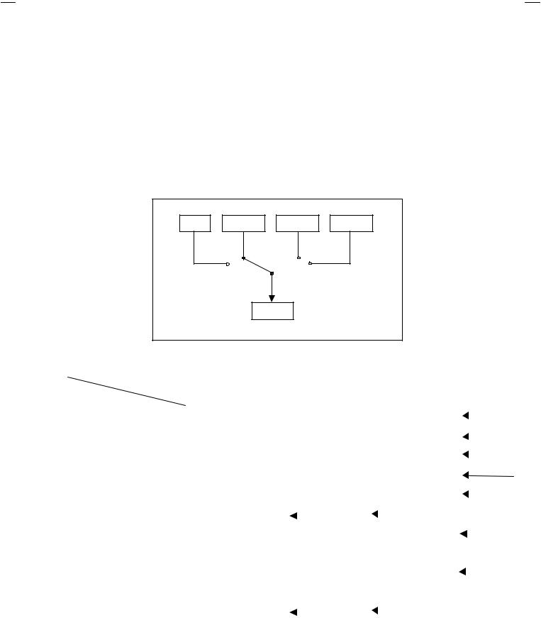
"Users can make VCR dubbing of picture and sound by controlling the AV selector to select an optional source at the EXT-2 output shown in figure.
TV |
EXT-1 |
EXT-3 |
EXT-4 |
|
|
EXT-2 |
|
MAIN DIFFERENCE LIST
|
|
Model Name |
AV28T25EKS |
AV28T25EKB |
AV28T55EKS |
AV28T25EIS |
|||||||||||
! |
|
|
|||||||||||||||
Part Name |
|
|
|
|
|
|
|
|
|
|
|
|
|||||
|
|
|
|
|
|
|
|
|
|
|
|
|
|
|
|
|
|
! |
F.CABI ASSY |
|
LC11313-002B-U |
LC11313-005B-U |
LC11313-002B-U |
|
|
|
|
|
|
|
|
||||
|
|
|
|
|
|
|
|
|
|||||||||
|
|
|
|
|
|
|
|
|
|
|
|
|
|
|
|
|
|
! |
REAR COVER |
|
LC11282-001C-U |
LC11282-002C-U |
LC11282-001C-U |
|
|
|
|
|
|
|
|
||||
|
|
|
|
|
|
|
|
|
|||||||||
|
|
|
|
|
|
|
|
|
|
|
|
|
|
|
|
|
|
! |
AV BOARD |
|
LC11010-004A-U |
LC11010-005A-U |
LC11010-004A-U |
|
|
|
|
|
|
|
|
||||
|
|
|
|
|
|
|
|
|
|||||||||
|
|
|
|
|
|
|
|
|
|
|
|
|
|
|
|
|
|
|
JVC MARK |
|
LC41250-002C-U |
LC41250-003C-U |
LC41250-002C-U |
|
|
|
|
|
|
|
|
||||
|
|
|
|
|
|
|
|
|
|
|
|
|
|
|
|
|
|
|
RC HAND UNIT |
|
RM-C55H-1C |
RM-C51-1C |
RM-C55H-1C |
|
|
|
|
|
|
|
|
||||
|
|
|
|
|
|
|
|
|
|
||||||||
|
|
|
|
|
|
|
|
|
|
|
|
|
|
|
|
|
|
|
REG CARD |
|
AEM3148-001-E |
|
|
|
|
|
|
|
|
|
|
|
|
|
|
|
|
|
|
|
|
|
|
|
|
|
|
|
|
|
|
||
|
|
|
|
|
|
|
|
|
|
|
|
|
|
|
|
||
|
|
|
|
|
|
|
|
|
|
|
|
|
|
|
|
|
|
|
CENTER PANEL |
|
LC21065-001A-U |
LC21065-002A-U |
LC21065-001A-U |
|
|
|
|
|
|
|
|
||||
|
|
|
|
|
|
|
|
|
|
||||||||
|
|
|
|
|
|
|
|
|
|
|
|
|
|
|
|
|
|
! |
RATING LABEL |
|
LC11364-003A-U |
LC11364-013A-U |
LC11364-012A-U |
LC11364-016A-U |
|||||||||||
|
|
|
|
|
|
|
|
|
|
|
|
|
|
|
|
|
|
! |
POWER KNOB |
|
LC31201-003A-U |
LC31201-006A-U |
LC31201-003A-U |
|
|
|
|
|
|
|
|
||||
|
|
|
|
|
|
|
|
|
|||||||||
|
|
|
|
|
|
|
|
|
|
|
|
|
|
|
|
|
|
|
EURO LABEL |
|
AEM1064-003-E |
AEM1064-025-E |
AEM1064-024-E |
AEM1064-005-E |
|||||||||||
|
|
|
|
|
|
|
|
|
|
|
|
|
|
|
|
|
|
|
MAIN PWB |
|
SJL-1002A-U2 |
|
|
|
|
|
|
SJL-1006A-U2 |
|||||||
|
|
|
|
|
|
|
|
||||||||||
|
|
|
|
|
|
|
|
||||||||||
|
|
|
|
|
|
|
|
|
|
|
|
|
|
|
|
|
|
No.51942 |
5 |

AV28T25EKS
AV28T25EKB
AV28T55EKS
AV28T25EIS
SPECIFIC SERVICE INSTRUCTIONS
DISASSEMBLY PROCEDURE
REMOVING THE REAR COVER
1.Unplug the power cord.
2.Remove the 13 screws marked A as shown in the Fig. 1.
3.Withdraw the rear cover toward you.
REMOVING THE SIDE CONTROL JACK ASSEMBLY
" After removing the rear cover.
1.Remove the screw marked B as shown in the Fig.1.
2.While slightly raise the side control jack assembly, remove the 2 claws under the side control jack assembly.
3.Disconnect the connector “SR ”, “SL”, “S”, “F” and “CN016” as shown in Fig 2.
REMOVING THE SIDE CONTROL PWB
" After removing the rear cover and side control jack assembly.
1.Remove the 3 claws C from back side of the side control jack assembly as shown in Fig.2.
2.Pull out the SIDE CONTROL PW B.
REMOVING THE CHASSIS
" After removing the rear cover.
1.Slightly raise the both sides of the chassis by hand and remove the two claws under the both sides of the chassis from the front cabinet.
2.Withdraw the chassis backward.
(If necessary, take off the wire clamp, connectors etc.)
REMOVING THE POWER & DEF. PWB
" After removing the CHASSIS.
1.Remove the 3 screws marked H as shown in the Fig.1.
2.Remove the POWER & DEF. PWB up ward.
REMOVING THE SPEAKER
" After removing the rear cover.
1. Remove the 2 screws marked D, and remove the speaker holder as shown in Fig. 1.
NOTE : When removing the screws marked D of the speaker remove the lower side screw first, and then remove the upper one.
2.Remove the 2 screws E attaching the speaker.
3.Follow the same steps when removing the other hand speaker.
REMOVING THE AV TERMINAL BOARD
" After removing the rear cover.
1.Remove the 3 screws marked F as shown in the Fig. 1.
2.Remove the 2 claws marked G under the CHASSIS as shown in Fig. 3.
3.Remove the AV TERMINAL BOARD slightly in the direction of arrow X as shown in Fig. 3.
CHECKING THE PW BOARD
To check the back side of the PW Board.
1)Pull out the chassis . (Refer to REMOVING THE CHASSIS).
2)Erect the chassis vertically so that you can easily check the back side of the PW Board.
[CAUTION]
"When erecting the chassis, be careful so that there will be no contacting with other PW Board.
"Before turning on power, make sure that the wire connector is properly connected.
"When conducting a check with power supplied, be sure to confirm that the CRT EARTH WIRE (BRAIDED ASS’Y) is connected to the CRT SOCKET PW board.
WIRE CLAMPING AND CABLE TYING
1. |
Be sure to clamp the wire. |
2. |
Never remove the cable tie used for tying the wires together. |
|
Should it be inadvertently removed, be sure to tie the wires with |
|
a new cable tie. |
|
|
X |
AV SW PWB |
|
|
|
|
Connector |
|
AV TERMINAL |
|
SR |
C |
|
|
BOARD |
|
||
SL |
|
|
|
S |
SIDE |
|
|
CONT ROL |
|
|
|
|
|
|
|
|
PWB |
|
G |
F |
|
|
|
|
|
|
|
CN016 |
C |
|
|
|
(Back view) |
|
G |
Fig. 2 |
|
|
Fig. 3 |
6 |
|
No.51942 |
|

FRONT CABINET
CRT
SOCKET
PWB
FRONT
CONT ROL
PWB
CONT ROL
BASE
B
 Fig.2
Fig.2
SIDE CONTROL
JACK ASSEMBLY
REAR COVER
H (×3)
AV SW
PWB
CLAW
MAIN
PWB
AV28T25EKS
AV28T25EKB
AV28T55EKS
AV28T25EIS
D (×2)
E(×2)
 SIDE
SIDE
SPEAKER
POWER & DEF.
PWB

 CLAW
CLAW
 CHASSIS
AV TERMINAL
BOARD
F (×3)
POWER CORD
A(×13)
Fig. 1
No.51942 |
7 |
AV28T25EKS
AV28T25EKB
AV28T55EKS
AV28T25EIS
REMOVING THE CRT
Replacement of the CRT should be performed by 2 or more persons.
• After removing the cover, chassis etc.,
1.Putting the CRT change table on soft cloth, the CRT change table should also be covered with such soft cloth (shown in Fig.4).
2.While keeping the surface of CRT down, mount the TV set on the CRT change table balanced will as shown in Fig.5.
3.Remove 4 screws marked by arrows with a box type screw driver as shown in Fig.5.
• Since the cabinet will drop when screws have been removed, be sure to support the cabinet with hands.
4.After 4 screws have been removed, put the cabinet slowly on cloth (At this time, be carefully so as not to damage the front surface of the cabinet) shown in Fig.6.
• The CRT should be assembled according to the opposite sequence of its dismounting steps.
The CRT change table should preferably be smaller that the CRT surface, and its height be about 35cm.
CRT CHANGE TABLE
APPROX.
35cm
CLOTH
Fig. 4
CRT
CRT CHANGE TABLE
BOX
TYPE
SCREW
DRIVER
Fig. 5
CRT
CABINET |
CRT |
|
|
|
CHANGE TABLE |
|
|
|
Fig. 6 |
8 |
No. 51942 |

REPLACEMENT OF MEMORY ICs
1. Memory ICs
This TV use memory ICs. In the memory ICs, there are memorized data for correctly operating the video and deflection circuits . When replacing
memory ICs, be sure to use ICs written with the initial values of data.
2. Procedure for replacing memory ICs
PROCEDURE
(1) Power off
Switch the power off and unplug the power cord from the outlet.
(2)Replace ICs.
Be sure to use memory ICs written with the initial data values.
(3)Power on
Plug the power cord into the outlet and switch the power on.
(4)Check and set SYSTEM CONSTANT SET :
* It must not adjust without signal.
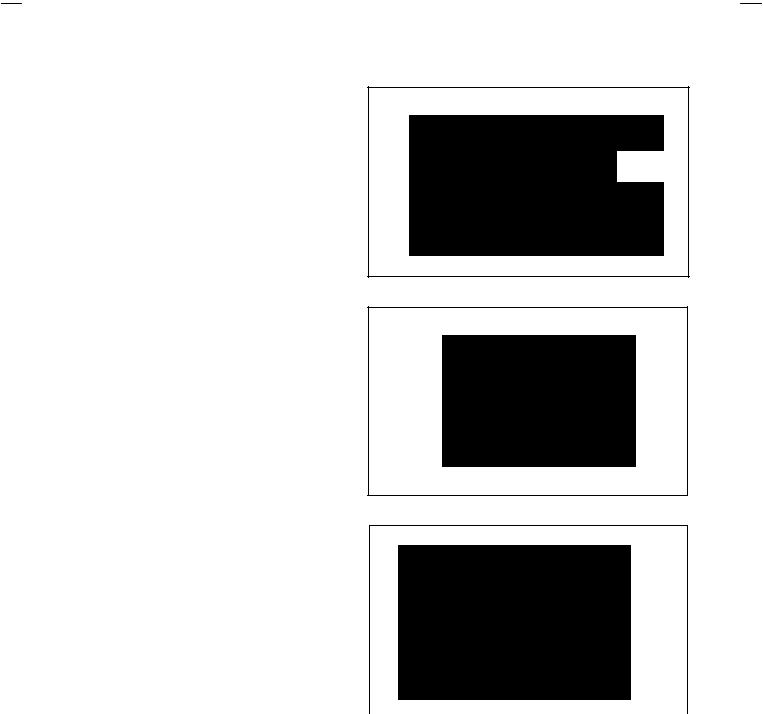
1)Press the INFORMATION key and the MUTING key of the REMOTE CONTROL UNIT simultaneously.
2)The SERVICE MENU screen of Fig. 1 will be displayed.
3)While the SERVICE MENU is displayed, press the INFORMATION key and MUTING key simultaneously, and the SYSTEM CONSTANT SET screen of Fig. 2 will be displayed.
4)Check the setting values of the SYSTEM CONSTANT SET of Table 1. If the value is different, select the setting item with the FUNCTION UP/DOWN key, and set the correct value with the FUNCTION -/+ key.
5)Press the MENU key to memorize the setting value.
6)Press the INFORMATION key twice, and return to the normal screen.
(5)Setting of receive channels
Set the receive channel.
For setting, refer to the OPERATING INSTRUCTIONS.
(6)User settings
Check the user setting values of Table 2, and if setting value is different, set the correct value.
For setting, refer to the OPERATING INSTRUCTIONS.
(7)Setting of SERVICE MENU
Verify the setting items of the SERVICE MENU of Table 3, and reset where necessary.
For setting, refer to the SERVICE ADJUSTMENTS.
AV28T25EKS
AV28T25EKB
AV28T55EKS
AV28T25EIS
SE RVICE ME NU
1. IF |
2. V/C |
3. AUDIO |
4. DEF |
5. VSM PRESET |
6. VPS |
7. SHIPPING (OFF)
1-7 : SELECT i : EXIT
Fig.1
SY STEM CONS TANT S ET
MODEL=JL_EURO(*.*** *)
1. DESTINATION : EK
JVC JL EURO V00
*** ****
- + OK: STORE |
i : EXIT |
Fig.2
NAME OF REMOTE CONTROL KEY
Names of key |
key |
INFORMATION i
MUTING
MENU |
|
OK |
|
|
▼ |
FUNCTION UP/DOWN |
|
|
|
|
▼ |
FUNCTION -/+ |
▼ |
▼ |
|
|
No. 51942 |
9 |
Loading...