


AV-32F475/Y
Table of contents
 Loading...
SERVICE MANUAL
COPYRIGHT © 2004 VICTOR COMPANY OF JAPAN, LIMITED
No.YA057
2004/3
COLOR TELEVISION
YA05720043
AV-32F475 /Y, AV-32F475 /Z,
AV-32F485
/Y, AV-32F485 /Z
TABLE OF CONTENTS
1 PRECAUTION. . . . . . . . . . . . . . . . . . . . . . . . . . . . . . . . . . . . . . . . . . . . . . . . . . . . . . . . . . . . . . . . . . . . . . . . . 1-3
2 SPECIFIC SERVICE INSTRUCTIONS . . . . . . . . . . . . . . . . . . . . . . . . . . . . . . . . . . . . . . . . . . . . . . . . . . . . . . 1-4
3 DISASSEMBLY . . . . . . . . . . . . . . . . . . . . . . . . . . . . . . . . . . . . . . . . . . . . . . . . . . . . . . . . . . . . . . . . . . . . . . . 1-6
4 ADJUSTMENT . . . . . . . . . . . . . . . . . . . . . . . . . . . . . . . . . . . . . . . . . . . . . . . . . . . . . . . . . . . . . . . . . . . . . . . 1-12
5 TROUBLE SHOOTING. . . . . . . . . . . . . . . . . . . . . . . . . . . . . . . . . . . . . . . . . . . . . . . . . . . . . . . . . . . . . . . . . 1-28
BASIC CHASSIS
GJ4
1-2 (No.YA057)
SPECIFICATION
Design & specifications are subject to change without notice.
Items
Contents
AV-32F475 AV-32F485
Dimensions (W × H × D) 93.9 cm × 68.5 cm × 57cm (37" × 27" × 22-1/2")
Mass 64.0kg (140.8Ibs)
TV RF System CCIR (M)
Color System NTSC
Sound System BTSC (Multi Channel Sound)
TV Receiving Channels
and Frequency
VHF low
VHF high
UHF
CATV
02ch~06ch : 54MHz~88MHz
07ch~13ch : 174MHz~216MHz
14ch~69ch : 470MHz~806MHz
54MHz~804MHz
Low Band : 02~06, A-8 by 02~06&01
High Band : 07~13 by 07~13
Mid Band : A~I by 14~22
Super Band : J~W by 23~36
Hyper Band : W+1~W+28 by 37~64
Ultra Band : W+29~W+84 by 65~125
Sub Mid Band : A8, A4~A1 by 01, 96~99
TV / CATV Total Channel 180 Channels
Intermediate Frequency Video IF
Sound IF
45.75 MHz
41.25 MHz (4.5MHz)
Color Sub Carrier 3.58 MHz
Power Input AC120V, 60Hz
Power Consumption 160W
Picture Tube (Visible size) 80cm (32”) Measured diagonally (H : 65.6cm × W : 49.6cm)
High Voltage 31.4kV ±1.3kV [at Zero beam current]
Speaker 6.5cm × 13cm (2-1/2" × 5"), Oval type × 2
Audio Power Output 7.5W + 7.5W 9W + 9W
Antenna Terminal (VHF / UHF) F-type connector, 75 Ω unbalanced
Video / Audio input
Input-1/2/3
Component Video
[Input-2]
S-video
[Input-1]
Video
Audio
RCA pin jack × 3
Y : 1V(p-p), negative sync, 75 Ω
Pb/Pr : 0.7V(p-p), 75 Ω
Mini DIN 4-pin × 1
Y : 1V(p-p), negative sync, 75 Ω
C : 0.286V(p-p)(burst signal), 75 Ω
1V(p-p), negative sync, 75 Ω, RCA pin jack × 3
500mV(rms)(-4dBs), high impedance, RCA pin jack × 6
Audio Output (Fix) 500mV(rms)(-4dBs), low Impedance, (400kHz when modulated 100%),
RCA pin jack × 2
Remote Control Unit RM-C1258G (AA/R6/UM-3 battery × 2)
(No.YA057)1-3
SECTION 1
PRECAUTION
1.1 SAFETY PRECAUTIONS
(1) The design of this product contains special hardware, many
circuits and components specially for safety purposes. For
continued protection, no changes should be made to the original
design unless authorized in writing by the manufacturer.
Replacement parts must be identical to those used in the original
circuits. Service should be performed by qualified personnel only.
(2) Alterations of the design or circuitry of the products should not be
made. Any design alterations or additions will void the
manufacturer's warranty and will further relieve the manufacturer
of responsibility for personal injury or property damage resulting
therefrom.
(3) Many electrical and mechanical parts in the products have special
safety-related characteristics. These characteristics are often not
evident from visual inspection nor can the protection afforded by them
necessarily be obtained by using replacement components rated for
higher voltage, wattage, etc. Replacement parts which have these
special safety characteristics are identified in the parts list of Service
manual. Electrical components having such features are
identified by shading on the schematics and by ( ) on the
parts list in Service manual. The use of a substitute replacement
which does not have the same safety characteristics as the
recommended replacement part shown in the parts list of Service
manual may cause shock, fire, or other hazards.
(4) Use isolation transformer when hot chassis.
The chassis and any sub-chassis contained in some products are
connected to one side of the AC power line. An isolation
transformer of adequate capacity should be inserted between the
product and the AC power supply point while performing any
service on some products when the HOT chassis is exposed.
(5) Don't short between the LIVE side ground and ISOLATED (NEU-
TRAL) side ground or EARTH side ground when repairing.
Some model's power circuit is partly different in the GND. The differ-
ence of the GND is shown by the LIVE : ( ) side GND, the ISOLAT-
ED (NEUTRAL) : ( ) side GND and EARTH : ( ) side GND.
Don't short between the LIVE side GND and ISOLATED (NEUTRAL)
side GND or EARTH side GND and never measure the LIVE side
GND and ISOLATED (NEUTRAL) side GND or EARTH side GND at
the same time with a measuring apparatus (oscilloscope etc.). If
above note will not be kept, a fuse or any parts will be broken.
(6) If any repair has been made to the chassis, it is recommended that
the B1 setting should be checked or adjusted (See B1 POWER
SUPPLY check).
(7) The high voltage applied to the picture tube must conform with that
specified in Service manual. Excessive high voltage can cause an
increase in X-Ray emission, arcing and possible component
damage, therefore operation under excessive high voltage
conditions should be kept to a minimum, or should be prevented.
If severe arcing occurs, remove the AC power immediately and
determine the cause by visual inspection (incorrect installation,
cracked or melted high voltage harness, poor soldering, etc.). To
maintain the proper minimum level of soft X-Ray emission,
components in the high voltage circuitry including the picture tube
must be the exact replacements or alternatives approved by the
manufacturer of the complete product.
(8) Do not check high voltage by drawing an arc. Use a high voltage
meter or a high voltage probe with a VTVM. Discharge the picture
tube before attempting meter connection, by connecting a clip lead
to the ground frame and connecting the other end of the lead
through a 10kΩ 2W resistor to the anode button.
(9) When service is required, observe the original lead dress. Extra
precaution should be given to assure correct lead dress in the high
voltage circuit area. Where a short circuit has occurred, those
components that indicate evidence of overheating should be
replaced. Always use the manufacturer's replacement
components.
(10) Isolation Check (Safety for Electrical Shock Hazard)
After re-assembling the product, always perform an isolation
check on the exposed metal parts of the cabinet (antenna
terminals, video/audio input and output terminals, Control knobs,
metal cabinet, screw heads, earphone jack, control shafts, etc.) to
be sure the product is safe to operate without danger of electrical
shock.
a) Dielectric Strength Test
The isolation between the AC primary circuit and all metal parts
exposed to the user, particularly any exposed metal part having a
return path to the chassis should withstand a voltage of 1100V AC
(r.m.s.) for a period of one second.
(. . . . Withstand a voltage of 1100V AC (r.m.s.) to an appliance rat-
ed up to 120V, and 3000V AC (r.m.s.) to an appliance rated 200V
or more, for a period of one second.) This method of test requires
a test equipment not generally found in the service trade.
b) Leakage Current Check
Plug the AC line cord directly into the AC outlet (do not use a line
isolation transformer during this check.). Using a "Leakage
Current Tester", measure the leakage current from each exposed
metal part of the cabinet, particularly any exposed metal part
having a return path to the chassis, to a known good earth ground
(water pipe, etc.). Any leakage current must not exceed 0.5mA AC
(r.m.s.).
However, in tropical area, this must not exceed 0.2mA AC (r.m.s.).
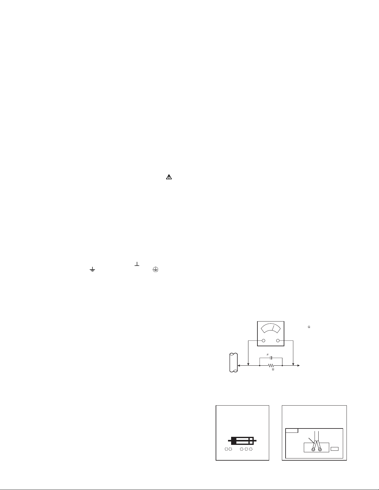
Alternate Check Method
Plug the AC line cord directly into the AC outlet (do not use a
line isolation transformer during this check.). Use an AC
voltmeter having 1000Ω per volt or more sensitivity in the
following manner. Connect a 1500Ω 10W resistor paralleled by
a 0.15µF AC-type capacitor between an exposed metal part and
a known good earth ground (water pipe, etc.). Measure the AC
voltage across the resistor with the AC voltmeter. Move the
resistor connection to each exposed metal part, particularly any
exposed metal part having a return path to the chassis, and
measure the AC voltage across the resistor. Now, reverse the
plug in the AC outlet and repeat each measurement. Any
voltage measured must not exceed 0.75V AC (r.m.s.). This
corresponds to 0.5mA AC (r.m.s.).
However, in tropical area, this must not exceed 0.3V AC
(r.m.s.). This corresponds to 0.2mA AC (r.m.s.).
(11) High voltage hold down circuit check.
After repair of the high voltage hold down circuit, this circuit shall
be checked to operate correctly.See item "How to check the high
voltage hold down circuit".
AC VOLTMETER
(HAVING 1000 /V,
OR MORE SENSITIVITY)
PLACE THIS PROBE
ON EACH EXPOSED
ME TAL PA RT
1500 10W
0.15 F AC-TYPE
GOOD EARTH GROUND
PWB
White line side
WHT
PW
POWER CORD
REPLACEMENT WARNING.
Connecting the white line side of power
cord to "WHT" character side.
A V
This mark shows a fast
operating fuse, the
letters indicated below
show the rating.
1-4 (No.YA057)
SECTION 2
SPECIFIC SERVICE INSTRUCTIONS
2.1 FEATURES
SMART CAPTION [AV-32F485]
Smart caption will appear when you press the MUTING button,
only on channels where the broadcast contains CLOSED
CAPTION information.
SMART SOUND
Decreases high sound levels, giving a regulated sound level.
FLAT SQUARE CRT
It became legible from any position by CRT with few reflection
and reflect lumps on the flat screen.
DIGITAL COMB FILTER
By the 3 line digital comb filter, the refreshed image can be
seen.
VIDEO STATUS
Expression of a favorite screen can be chosen by the VIDEO
STATUS function.
[STANDARD ↔ DYNAMIC ↔ THEATER ↔ GAME]
COMPONENT INPUT
Since the component signal input terminal is equipped, it
reappears direct without deteriorating the signal from DVD.
V-CHIP
Since the V-CHIP is built in, it can choose, view and listen to a
healthy program.
MTS STEREO
The voice multiplex function of the MTS system is built in.
(MTS = Multi channel Television Sound system)
RETURN PLUS
You program a specific channel to return to while scanning
through the channels using the CH+ and CH - keys.
VIDEO INPUT LABEL
This function is used to label video input connections for the
onscreen displays.
WORLD CLOCK
The world clock feature provides time differences for some of
the major cities around the world in real time.
BBE
High definition audio adds natural, clear and extraordinary
sound quality to any program.
A.H.S. [AV-32F485]
Adds a more spacious surround sound. Music gives basic
effect and Movie for more effect.
HYPER SURROUND [AV-32F475]
Creates a deep, three-dimensional sound effect by channeling
the audio through the TV's front-firing speakers.
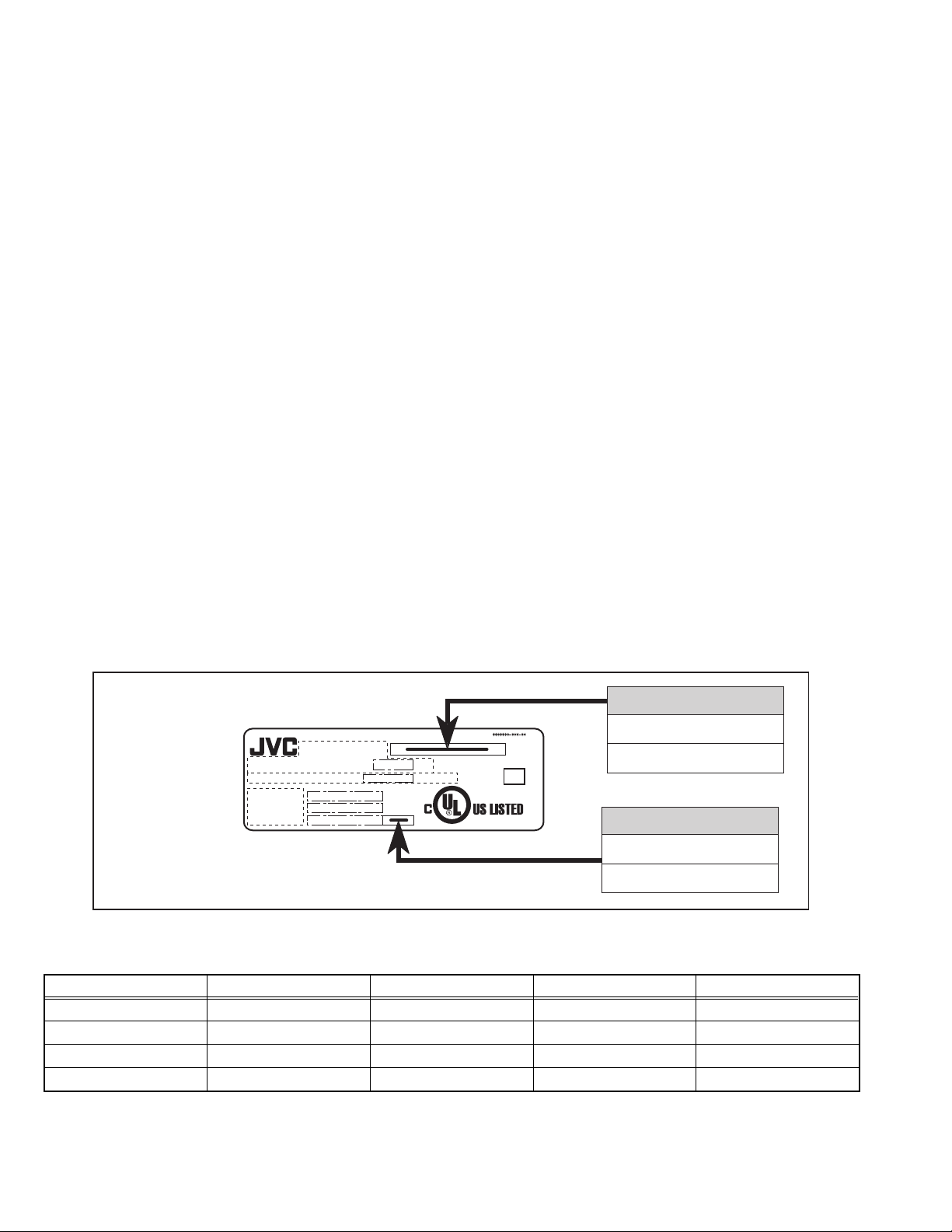
2.2 HOW TO IDENTIFY MODELS
How to recognize from the appearance of the model concerned is written below. Please distinguish from several contents currently
printed on the rating label
2.3 MAIN DIFFERENCE LIST
The difference between Y models and Z models are in the PICTURE TUBE.
AV-32F475
AV-32F485
MODEL NAME
Y
Z
DISTINGUISH NAME
MODEL NO.
AC 120V 60Hz
W
TV SCREEN SIZE : DIAGONAL
INCHES
CHASSIS NO.
MANUFACTURED
SERIAL NO.
VIDEO EQUIPMENT
4C43
ME
Item AV-32F475/Y AV-32F475/Z AV-32F485/Y AV-32F485/Z
PICTURE TUBE (ITC) A80AKS90X03 A80ERF082X17 A80AKS90X03 A80ERF082X17
SMART CAPTION NO ← YES ←
A.H.S. NO ← YES ←
HYPER SURROUND YES ← NO ←
(No.YA057)1-5
2.4 TECHNICAL INFORMATION
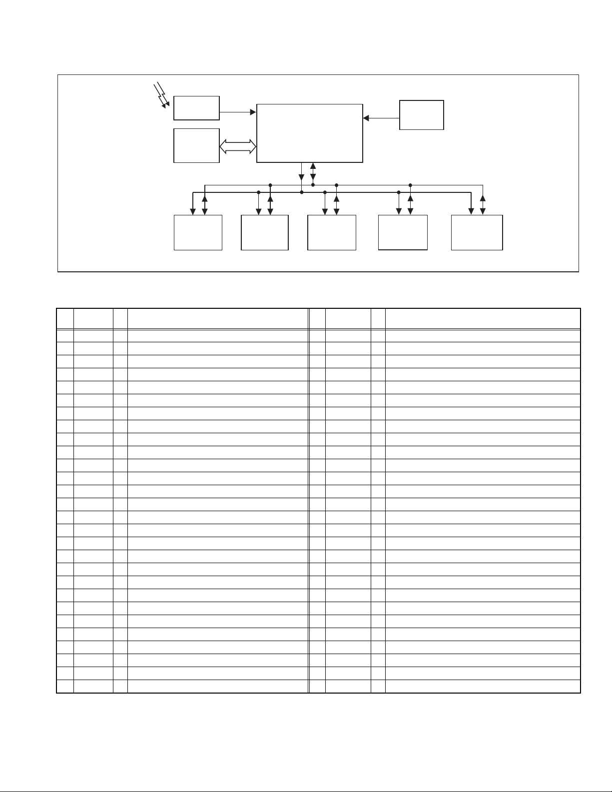
2.4.1 SYSTEM BLOCK DIAGRAM
2.4.2 MAIN MI-COM (CPU) PIN FUNCTION
SCL1
SDA1
AFT1
SCL0 SDA0
SCL0 SDA0 SCL0 SDA0
MAIN MI-COM /
VIDEO PROCESS /
DEF. PROCESS
IC101
IF DET
TU001
TUNER
IC5501
SCL0 SDA0
IC5001
MTS
TONE/VOL
SCL0 SDA0
IC5201
3-LINE YC SEP.
SCL0 SDA0
IC502
D-A CONVERTER
LATCH&
AV SW
IC201
REMOCON
REMOCON
RECEIVER
IC702
MEMORY
Pin
No.
Pin name I/O Function
Pin
No.
Pin name I/O Function
1 MTS_ADJ I Not used 29 YC_GND - GND
2 AFT1 I AFT voltage for tuner (Tuning frequency control) 30 V1_IN I Not used
3 KEY I Key scan for front control [No signal : H] 31 ABCL I Current for automatic beam (brightness)/contrast limit
4 uP_DVss - GND 32
MONITOR_OUT
O Not used
5 Reset I CPU reset 33 BLACK_DET - Black level detection filter
6 8MHz_OUT O CPU system clock : 8MHz oscillation 34 SVM_OUT O Y signal for velocity scan modulation
7 8MHz_IN I CPU system clock : 8MHz oscillation 35 APL_FIL - Average picture level filter
8 TEST - GND 36 APC_FIL - Automatic phase control filter
9 uP_DVD D - 5V 37 fsc_OUT O Color sub carrier (3.58MHz) for 3-line digital comb filter [IC5201]
10 AGC_MUTE O AGC muting for tuner (when channel select) [Muting : H] 38 YC_Vcc - 5V (for video process circuit)
11 uP_VVSS - GND 39 R_OUT O R signal
12 TV_HGND - GND 40 G_OUT O G signal
13 FBP_SCP I Flyback pulse (H. pulse) 41 B_OUT O B signal
14 HOUT O H. drive (oscillation) 42 RGB_Vcc - 9V (for RGB process circuit)
15 H_Vcc - 9V (for H. oscillation start) 43 IK_IN I Not used
16 HAFC_1 - H. AFC filter 44 TV_DGND - GND
17 Vsaw - V. saw filter 45 uP_AGND - GND
18 VOUT O V. drive 46 uP_AVdd - 5V
19 EW_OUT O Parabola waveform (for sidepin correection) 47 MAIN_POWER O Power on/off switching control [Powen on : L]
20 X-RAY I X-ray detection (for protection) [Detection : H] 48 PANORAMA I Not used
21 Ys I Not used 49 SDAO I/O Data for Inter IC control bus (for various devices)
22 Cb_IN I Cb (external) signal 50 SCLO O Clock for Inter IC control bus (for various devices)
23 Y_IN I Y (external) signal 51 SDA1 I/O Data for Inter IC control bus (for main memory)
24 Cr_IN I Cr (external) signal 52 A_MUTING O Audio muting [Muting : H]
25 TV_DVcc - 3.3V 53 SCL1 O Clock for Inter IC control bus (for main memory)
26 V3IN/CIN I Chroma signal (for YC separation output) 54 LED O POWER / ON TIMER LED lndication [lighting : L]
27 EHT_IN I Not used 55 REMOCON I Remote control sensor input [No input : H]
28 V2_IN/Y_IN I Y signal (for YC separation output) 56 ASP_ABL I Not used

1-6 (No.YA057)
SECTION 3
DISASSEMBLY
3.1 DISASSEMBLY PROCEDURE
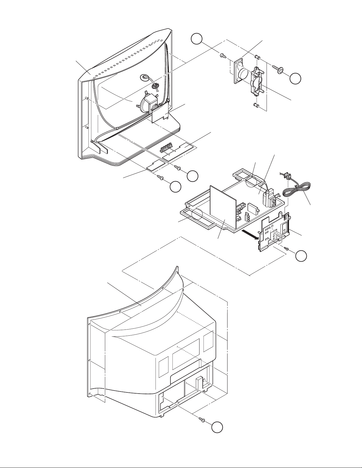
3.1.1 REMOVING THE REAR COVER
(1) Disconnect the power plug.
(2) Remove the 11 screws [A].
(3) Withdraw the REAR COVER backward.
3.1.2 REMOVING THE AV TERMINAL BOARD
• Remove the REAR COVER.
(1) Remove the 5 screws [B].
(2) Withdraw the AV TERMINAL BOARD toward you.
3.1.3 REMOVING THE CHASSIS
• Remove the REAR COVER.
• Remove the AV TERMINAL BOARD.
(1) Slightly raise the both sides of CHASSIS by hand.
(2) Remove the 2 claws under the both side of the CHASSIS
from the front cabinet.
(3) Withdraw the CHASSIS backward.
(If necessary, remove the wire clamp, connectors etc.)
3.1.4 REMOVING THE SPEAKER
• Remove the REAR COVER.
(1) Remove the 2 screws [C].
(2) Remove the 2 screws [D] and remove the SPEAKER.
(3) Follow the same steps when removing the other hand
SPEAKER.
NOTE :
When remove the 2 screws [C] of the SPEAKER, remove the
lower side screw first, and then remove the upper one.
3.1.5 REMOVING THE LED & POWER SW PWB
• Remove the REAR COVER.
(1) Remove the 2 screws [E].
(2) Withdraw the LED & POWER SW PWB toward you.
*If necessary, remove the wire clamp, connector etc.
3.1.6 REMOVING THE FRONT CONTROL PWB
• Remove the REAR COVER.
(1) Remove the 2 screws [F].
(2) Withdraw the FRONT CONTROL PWB toward you.
*If necessary, remove the wire clamp, connector etc.
3.1.7 CHECKING THE CHASSIS
To check the PW Board from back side.
(1) Pull out the CHASSIS (refer to REMOVING THE CHASSIS).
(2) Erect the CHASSIS vertically with the HVT side facing up
so that you can easily check the back side of the PW board.
CAUTION :
• When erecting the CHASSIS, be careful so that there will be
no contacting with other PW Board.
• Before turning on power, make sure that the wire connector
is properly connected.
• When conducting a check with power supplied, be sure
to confirm that the CRT EARTH WIRE (BRAIDED ASS'Y)
is connected to the CRT SOCKET PWB.
3.1.8 WIRE CLAMPING AND CABLE TYING
(1) Be sure to clamp the wire.
(2) Never remove the cable tie used for tying the wires together.
Should it be inadvertently removed, be sure to tie the wires
with a new cable tie.
(No.YA057)1-7
Fig.1
A
REAR COVER
C
D
E
F
FRONT CONTROL PWB
CRT SOCKET PWB
LED & POWER SW PWB
SPEAKER
SPEAKER HOLDER
FRONT CABINET
B
CLAW
CLAW
AV SELECTOR
PWB
MAIN PWB
AV TERMINAL
BOARD
POWER CORD
1-8 (No.YA057)
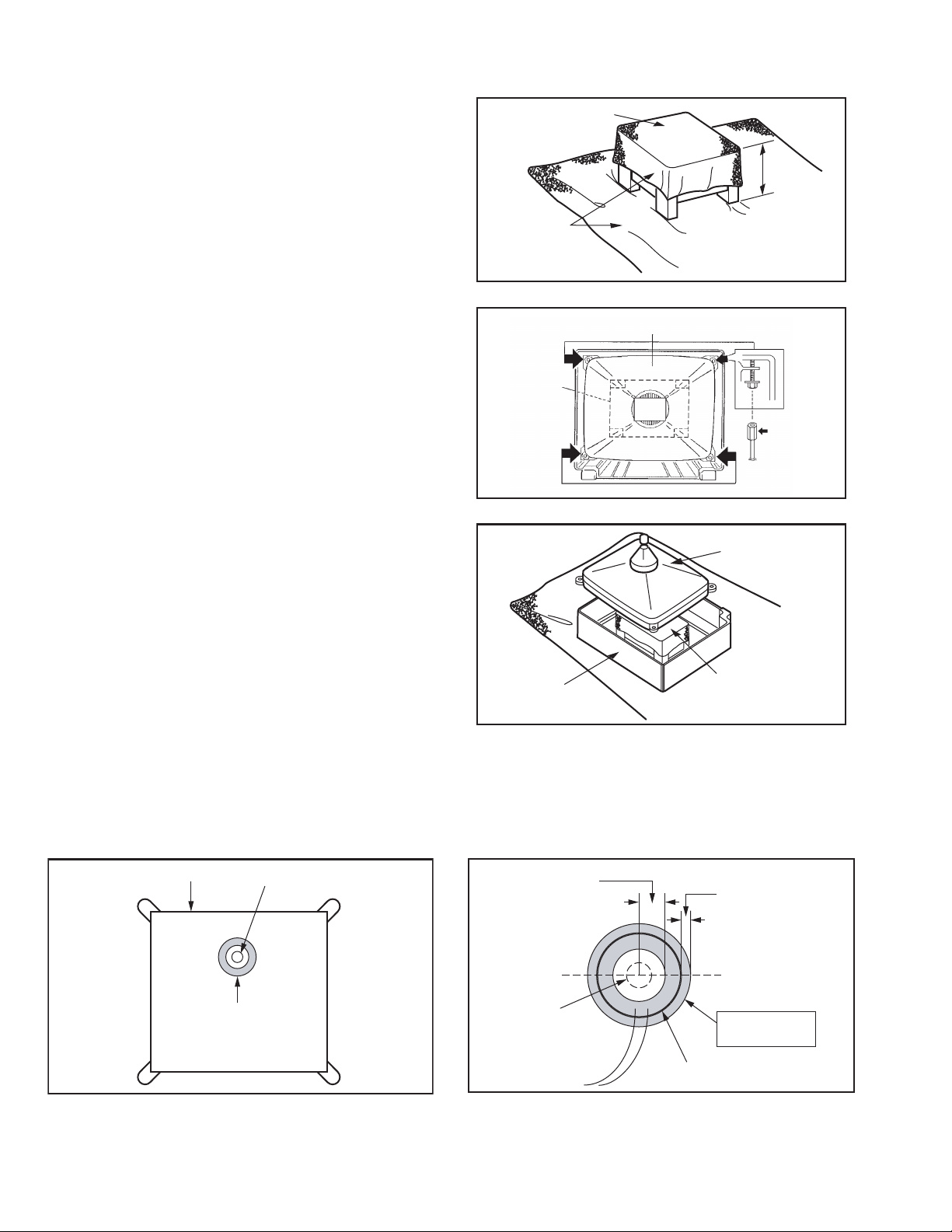
3.1.9 REMOVING THE CRT
NOTE:
• Replacement of the CRT should be performed by 2 or more
persons.
• After removing the REAR COVER, CHASSIS etc.,
(1) Putting the CRT change table on soft cloth, the CRT
change table should also be covered with such soft cloth
(shown in Fig. 3).
(2) While keeping the surface of CRT down, mount the TV set
on the CRT change table balanced will as shown in Fig. 3.
(3) Remove 4 screws marked by arrows with a box type screw-
driver as shown in Fig. 4.
NOTE:
Since the cabinet will drop when screws have been re-
moved, be sure to support the cabinet with hands.
(4) After 4 screws have been removed, put the cabinet slowly
on cloth (At this time, be carefully so as not to damage the
front
surface of the cabinet) shown in Fig. 5.
NOTE:
• The CRT should be assembled according to the oppo-
site sequence of its dismounting steps.
• The CRT change table should preferably be smaller
that the CRT surface, and its height be about 35cm.
Fig.3
Fig.4
Fig.5
COATING OF SILICON GREASE FOR ELECTRICAL INSULATION ON THE CRT ANODE CAP SECTION.
Subsequent to replacement of the CRT and HV transformer or repair of the anode cap, etc. by dismounting them, be sure to coat
silicon grease for electrical insulation as shown in Fig.6.Wipe around the anode button with clean and dry cloth. (Fig.6)Coat silicon
grease on the section around the anode button. At this time, take care so that any silicon greases dose not sticks to the anode but-
ton. (Fig.7)
Silicon grease product No. KS - 650N
Fig.6
Fig.7
CRT CHANGE TABLE
APPROX.
35cm
CLOTH
CRT
BOX
TYPE
SCREW
DRIVER
CRT
CHANGE
TABLE
CRT
CHANGE TABLE
CRT
CABINET
Anode button
CRT
Silicon grease
coating
Silicon grease
should be coated
by 5mm or more
from the outside
diameter of anode
cap.
Approx.
20mm (Do not
coat grease on
this section
Anode button
(No sticking of
silicon grease)
Anode cap
Coating position
of silicon grease
(No.YA057)1-9
3.2 MEMORY IC REPLACEMENT
• This model uses the memory IC.
• This memory IC stores data for proper operation of the video
and drive circuits.
• When replacing, be sure to use an IC containing this (initial val-
ue) data.
3.2.1 MEMORY IC REPLACEMENT PROCEDURE
1. Power off
Switch off the power and disconnect the power cord from the
wall outlet.
2. Replace the memory IC
Be sure to use a memory IC written with the initial setting data.
3. Power on
Connect the power cord to the wall outlet and switch on the
power.
4. Receiving channel setting
Refer to the OPERATING INSTRUCTIONS (USER'S GUIDE)
and set the receive channels (Channels Preset) as described.
5. User settings
Check the user setting items according to the "FACTORY
SETTING ITEM" table.
Where these do not agree, refer to the OPERATING
INSTRUCTIONS (USER'S GUIDE) and set the items as
described.
6. SERVICE MODE setting
Verify what to set in the SERVICE MODE, and set whatever is
necessary(Fig.1) .
Refer to the SERVICE ADJUSTMENT for setting.
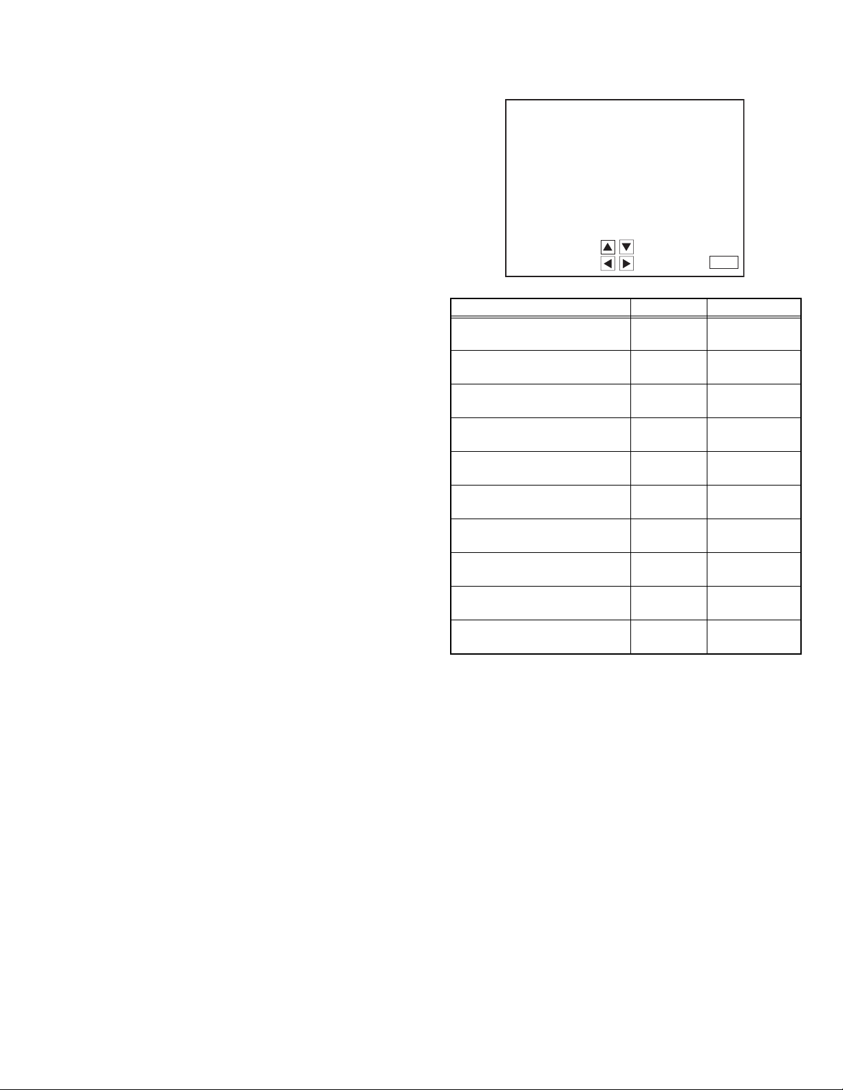
3.2.2 SERVICE MODE SETTING ITEMS
Fig.1
Setting items Settings Item No.
1. V/C
(Video setting)
Adjust S01~S48
2. DEF
(Deflection setting)
Adjust D01~D33
3. SOUND(A)
(Audio setting)
Adjust A01~A08
4. OTHERS [Do not adjust]
(Factory setting)
Fixed F01~F18
5. 3L Y/C [Do not adjust]
(Y/C Separate setting)
Fixed LYC01~LYC12
7. LOW LIGHT
(White balance setting)
Adjust ---
8. HIGH LIGHT
(White balance setting)
Adjust ---
9. VCO
(VCO setting)
Adjust ---
11. I2C BUS [Do not adjust]
(I
2
C BUS setting)
Fixed ---
12.SYSTEM (SYS)
(System constant setting)
Fixed SYS01~SYS25
1.
3.
5.
7.
9.
11.
2.
4.
8.
12.
SERV ICE MENU
DEF(D)
OTHERS(F)
HIGH LIGHT
SYSTEM(SYS)
SELECT BY
OPERATE BY
EXIT BY
EXIT
SERVICE MENU
V/C(S)
SOUND(A)
3L Y/C(LYC)
LOW LIGHT
VCO
I2C BUS
Loading...