


 Loading...
SERVICE MANUAL
COLOR TELEVISION
AV-27FA54/ASA, AV-27FA54/AZA,
AV-32FA54/AYA, AV-32FA54/AZA,
AV-36FA54/AYA
BASIC CHASSIS
GJ2
PIP
EZ SURF CHANNEL |
ON/MOVE |
INPUT SOURCE FREEZE SWAP
SOUND
C.C.
TABLE OF CONTENTS
1 PRECAUTION. . . . . . . . . . . . . . . . . . . . . . . . . . . . . . . . . . . . . . . . . . . . . . . . . . . . . . . . . . . . . . . . . . . . . . . . . 1-3 2 SPECIFIC SERVICE INSTRUCTIONS . . . . . . . . . . . . . . . . . . . . . . . . . . . . . . . . . . . . . . . . . . . . . . . . . . . . . . 1-4 3 DISASSEMBLY . . . . . . . . . . . . . . . . . . . . . . . . . . . . . . . . . . . . . . . . . . . . . . . . . . . . . . . . . . . . . . . . . . . . . . . 1-9 4 ADJUSTMENT . . . . . . . . . . . . . . . . . . . . . . . . . . . . . . . . . . . . . . . . . . . . . . . . . . . . . . . . . . . . . . . . . . . . . . . 1-15 5 TROUBLE SHOOTING. . . . . . . . . . . . . . . . . . . . . . . . . . . . . . . . . . . . . . . . . . . . . . . . . . . . . . . . . . . . . . . . . 1-39
COPYRIGHT © 2003 VICTOR COMPANY OF JAPAN, LIMITED
No.52115
2003/6
SPECIFICATION
Items |
|
|
|
|
|
|
|
Contents |
|
|
|
|
||
|
|
AV-27FA54 |
|
|
AV-32FA54 |
|
AV-36FA54 |
|||||||
|
|
|
|
|
|
|
||||||||
|
|
|
|
|
|
|
|
|
|
|
|
|||
Dimensions (W × H × D) |
|
|
82.9 cm × |
59.3 cm × |
51.9cm |
|
93.9 cm × |
68.5 cm × 57.0cm |
102.3 cm × |
75.6 cm × |
61.3cm |
|||
|
|
|
|
(32-3/4" × |
23-3/8" × |
20-1/2") |
|
(37" × |
27" × 22-1/2") |
|
(40-3/8" × |
29-7/8" × |
24-1/4") |
|
Mass |
|
|
43.0kg (94.6Ibs) |
|
|
|
64.0kg (140.8Ibs) |
|
85.0kg (187.0Ibs) |
|
||||
TV RF System |
|
|
CCIR(M) |
|
|
|
|
|
|
|
|
|
|
|
Color System |
|
|
NTSC |
|
|
|
|
|
|
|
|
|
|
|
Sound System |
|
|
BTSC (Multi Channel Sound) |
|
|
|
|
|
||||||
TV Receiving Channels |
|
|
VHF LOW |
02ch~06ch : 54MHz~88MHz |
|
|
|
|
|
|||||
and Frequency |
|
|
|
|
|
|
|
|
|
|||||
|
|
VHF HIGH |
07ch~13ch : 174MHz~216MHz |
|
|
|
|
|
||||||
|
|
|
UHF |
14ch~69ch : 470MHz~806MHz |
|
|
|
|
|
|||||
|
|
|
CATV |
54MHz~804MHz |
|
|
|
|
|
|
|
|
|
|
|
|
|
|
Low Band : 02~06, A-8 by 02~06&01 |
|
|
|
|
||||||
|
|
|
|
High Band : 07~13 by 07~13 |
|
|
|
|
|
|||||
|
|
|
|
Mid Band : A~I by 14~22 |
|
|
|
|
|
|
||||
|
|
|
|
Super Band : J~W by 23~36 |
|
|
|
|
|
|||||
|
|
|
|
Hyper Band : W+1~W+28 by 37~64 |
|
|
|
|
|
|||||
|
|
|
|
Ultra Band : W+29~W+84 by 65~125 |
|
|
|
|
||||||
|
|
|
|
Sub Mid Band : A8, A4~A1 by 01, 96~99 |
|
|
|
|
||||||
TV / CATV Total Channel |
|
|
180 Channels |
|
|
|
|
|
|
|
|
|
||
Intermediate Frequency |
|
|
Video IF Carrier |
45.75 MHz |
|
|
|
|
|
|
|
|
|
|
|
|
Sound IF Carrier |
41.25 MHz (4.5MHz) |
|
|
|
|
|
|
|
|
|||
Color Sub Carrier |
|
|
3.58 MHz |
|
|
|
|
|
|
|
|
|
|
|
Power Input |
|
|
AC120V , 60Hz |
|
|
|
|
|
|
|
|
|
||
Power Consumption |
|
|
|
140W |
|
|
|
|
160W |
|
|
← |
|
|
Picture Tube (Visible size) |
|
|
68cm (27”) |
|
|
80cm (32”) |
|
90cm (36”) |
|
|||||
|
|
|
|
Measured diagonally |
|
Measured diagonally |
|
Measured diagonally |
||||||
|
|
|
|
(H : 54.4cm × W : 41.8cm) |
|
(H : 65.6cm × W : 49.6cm) |
(H : 74.0cm × W : 55.9cm) |
|||||||
High Voltage |
|
|
30.0kV ±1.3kV |
|
|
31.4kV ±1.3kV |
|
|
← |
|
||||
Speaker |
|
|
6.5cm × 13cm (2-1/2" × |
5"), Oval type × 2 |
|
|
|
|
||||||
Audio Power Output |
|
|
10W + 10W |
|
|
|
|
|
|
|
|
|
||
Antenna Terminal (VHF / UHF) |
|
F-type connector, 75 Ω |
unbalanced |
|
|
|
|
|
||||||
Input1 (Rear) |
|
|
Video |
1V(p-p), negative sync, 75 Ω |
, RCA pin jack × 1 |
|
|
|
|
|||||
|
|
|
S-video |
Mini DIN 4-pin × 1 |
|
|
|
|
|
|
|
|
|
|
|
|
|
|
Y : 1V(p-p), negative sync, 75 Ω |
|
|
|
|
|
|||||
|
|
|
|
C : 0.286V(p-p)(burst signal), 75 Ω |
|
|
|
|
|
|||||
|
|
|
Audio |
500mV(rms)(-4dBs), high impedance, RCA pin jack × |
2 |
|
|
|
||||||
Input2 (Rear) |
|
|
Video |
1V(p-p), negative sync, 75 Ω |
, RCA pin jack × 1 |
|
|
|
|
|||||
|
|
Component Video |
Y : 1V(p-p), negative sync, 75 Ω , RCA pin jack × 1 |
|
|
|
|
|||||||
|
|
|
|
Pb/Pr : 0.7V(p-p), 75 Ω |
, RCA pin jack × 2 |
|
|
|
|
|||||
|
|
|
Audio |
500mV(rms)(-4dBs), high impedance, RCA pin jack × |
2 |
|
|
|
||||||
Input3 (Front) |
|
|
Video |
1V(p-p), negative sync, 75 Ω |
, RCA pin jack × 1 |
|
|
|
|
|||||
|
|
|
Audio |
500mV(rms)(-4dBs), high impedance, RCA pin jack × |
2 |
|
|
|
||||||
Input4 (Rear) |
|
Component Video |
Y : 1V(p-p), negative sync, 75 Ω , RCA pin jack × 1 |
|
|
|
|
|||||||
|
|
|
|
Pb/Pr : 0.7V(p-p), 75 Ω |
, RCA pin jack × 2 |
|
|
|
|
|||||
|
|
|
Audio |
500mV(rms)(-4dBs), high impedance, RCA pin jack × |
2 |
|
|
|
||||||
Subwoofer Output (Audio) |
|
|
More than 0 to 1000mV (rms)(+2.2dBs), low impedance, RCA pin jack × 1 |
|
||||||||||
Audio Output (Fix) |
|
|
500mV(rms)(-4dBs), low Impedance, (400kHz when modulated 100%), |
|
||||||||||
|
|
|
|
RCA pin jack × 2 |
|
|
|
|
|
|
|
|
|
|
AV COMPULINK lll |
|
|
3.5mm mini jack × |
1 |
|
|
|
|
|
|
|
|
||
Remote Control Unit |
|
|
RM-C1251G (AA/R6/UM-3 battery × |
2) |
|
|
|
|
||||||
Design & specifications are subject to change without notice. |
|
|
|
|
|
|
|
|
|
|||||
1-2 (No.52115) |
|
|
|
|
|
|
|
|
|
|
|
|
|
|
SECTION 1 PRECAUTION
1.1SAFETY PRECAUTIONS
(1)The design of this product contains special hardware, many circuits and components specially for safety purposes. For continued protection, no changes should be made to the original design unless authorized in writing by the manufacturer. Replacement parts must be identical to those used in the original circuits. Service should be performed by qualified personnel only.
(2)Alterations of the design or circuitry of the products should not be made. Any design alterations or additions will void the manufacturer's warranty and will further relieve the manufacturer of responsibility for personal injury or property damage resulting therefrom.
(3)Many electrical and mechanical parts in the products have special safety-related characteristics. These characteristics are often not evident from visual inspection nor can the protection afforded by them necessarily be obtained by using replacement components rated for higher voltage, wattage, etc. Replacement parts which have these special safety characteristics are identified in the parts list of Service manual. Electrical components having such features are identified by shading on the schematics and by (  ) on the parts list in Service manual. The use of a substitute replacement which does not have the same safety characteristics as the recommended replacement part shown in the parts list of Service manual may cause shock, fire, or other hazards.
(4)Use isolation transformer when hot chassis.
The chassis and any sub-chassis contained in some products are connected to one side of the AC power line. An isolation transformer of adequate capacity should be inserted between the product and the AC power supply point while performing any service on some products when the HOT chassis is exposed.
(5)Don't short between the LIVE side ground and ISOLATED (NEUTRAL) side ground or EARTH side ground when repairing.
Some model's power circuit is partly different in the GND. The difference of the GND is shown by the LIVE : (  ) side GND, the ISOLATED (NEUTRAL) : (
  ) side GND and EARTH : (
  ) side GND.
Don't short between the LIVE side GND and ISOLATED (NEUTRAL) side GND or EARTH side GND and never measure the LIVE side GND and ISOLATED (NEUTRAL) side GND or EARTH side GND at the same time with a measuring apparatus (oscilloscope etc.). If above note will not be kept, a fuse or any parts will be broken.
(6)If any repair has been made to the chassis, it is recommended that the B1 setting should be checked or adjusted (See B1 POWER SUPPLY check).
(7)The high voltage applied to the picture tube must conform with that specified in Service manual. Excessive high voltage can cause an increase in X-Ray emission, arcing and possible component damage, therefore operation under excessive high voltage conditions should be kept to a minimum, or should be prevented. If severe arcing occurs, remove the AC power immediately and determine the cause by visual inspection (incorrect installation, cracked or melted high voltage harness, poor soldering, etc.). To maintain the proper minimum level of soft X-Ray emission, components in the high voltage circuitry including the picture tube must be the exact replacements or alternatives approved by the manufacturer of the complete product.
(8)Do not check high voltage by drawing an arc. Use a high voltage meter or a high voltage probe with a VTVM. Discharge the picture tube before attempting meter connection, by connecting a clip lead to the ground frame and connecting the other end of the lead through a 10kΩ 2W resistor to the anode button.
(9)When service is required, observe the original lead dress. Extra precaution should be given to assure correct lead dress in the high voltage circuit area. Where a short circuit has occurred, those components that indicate evidence of overheating should be replaced. Always use the manufacturer's replacement components.
(10)Isolation Check (Safety for Electrical Shock Hazard)
After re-assembling the product, always perform an isolation check on the exposed metal parts of the cabinet (antenna terminals, video/audio input and output terminals, Control knobs, metal cabinet, screw heads, earphone jack, control shafts, etc.) to be sure the product is safe to operate without danger of electrical
shock.
a)Dielectric Strength Test
The isolation between the AC primary circuit and all metal parts exposed to the user, particularly any exposed metal part having a return path to the chassis should withstand a voltage of 1100V AC (r.m.s.) for a period of one second.
(. . . . Withstand a voltage of 1100V AC (r.m.s.) to an appliance rated up to 120V, and 3000V AC (r.m.s.) to an appliance rated 200V or more, for a period of one second.) This method of test requires a test equipment not generally found in the service trade.
b)Leakage Current Check
Plug the AC line cord directly into the AC outlet (do not use a line isolation transformer during this check.). Using a "Leakage Current Tester", measure the leakage current from each exposed metal part of the cabinet, particularly any exposed metal part having a return path to the chassis, to a known good earth ground (water pipe, etc.). Any leakage current must not exceed 0.5mA AC (r.m.s.).
However, in tropical area, this must not exceed 0.2mA AC (r.m.s.).
Alternate Check Method
Plug the AC line cord directly into the AC outlet (do not use a line isolation transformer during this check.). Use an AC voltmeter having 1000Ω per volt or more sensitivity in the following manner. Connect a 1500Ω 10W resistor paralleled by a 0.15µF AC-type capacitor between an exposed metal part and a known good earth ground (water pipe, etc.). Measure the AC voltage across the resistor with the AC voltmeter. Move the resistor connection to each exposed metal part, particularly any exposed metal part having a return path to the chassis, and measure the AC voltage across the resistor. Now, reverse the plug in the AC outlet and repeat each measurement. Any voltage measured must not exceed 0.75V AC (r.m.s.). This corresponds to 0.5mA AC (r.m.s.).
However, in tropical area, this must not exceed 0.3V AC (r.m.s.). This corresponds to 0.2mA AC (r.m.s.).
AC VOLTMETER (HAVING 1000 /V,
/V,
OR MORE SENSITIVITY)
0.15 F AC-TYPE |
|
||
|
|
PLACE THIS PROBE |
|
1500 |
10W |
ON EACH EXPOSED |
|
METAL PART |
|||
|
|
||
GOOD EARTH GROUND
(11)High voltage hold down circuit check.
After repair of the high voltage hold down circuit, this circuit shall be checked to operate correctly.See item "How to check the high voltage hold down circuit".
This mark shows a fast operating fuse, the letters indicated below show the rating.
 A
A 
 V
V
POWER CORD REPLACEMENT WARNING.
Connecting the white line side of power cord to "WHT" character side.
PWB |
White line side |
PW |
WHT |
(No.52115)1-3

SECTION 2
SPECIFIC SERVICE INSTRUCTIONS
2.1FEATURES
•New chassis (GJ2) design enables use of a single board with simplified circuitry.
•Users can make fun to connect the DVD player with the component video signal input terminal.
•Provided with miniature tuner (TV/CATV).
•Multifunctional remote control permits picture adjustment.
•Adoption of the CHANNEL GUARD function prevents the specific channels from being selected, unless the "ID number" is key in.
•I2C bus control utilizes single chip ICs.
•Adoption of the VIDEO STATUS / THEATER PRO. function.
•Adoption of the ON/OFF TIMER and SLEEP TIMER function.
•Built-in V-CHIP system.
2.2HOW TO IDENTIFY MODELS
•Closed-caption broadcasts can be viewed.
•Built-in AHS (Advanced Hyper Surround) system.
•S-VIDEO input terminal for taking best advantage of Super VHS.
•Digital Comb filter Improved picture quality.
•Adoption of the ASPECT MODE (4:3/ 16:9) function.
•By pushing the EZ SURF key, Back Program Information can be displayed in written from program Information uses a CALL LETTER (broadcasting station ID), a Network name and a Program name of XDS data, and collectÅfs tuning of the tuner for PIP one by one.
•Two programs can be displayed on the screen by the 2 tuners PIP circuit.
 How to recognize from the appearance of the model concerned is written below. Please distinguish from several contents currently printed on the rating label.

 MODEL NO.
AC 120V 60Hz  W
W
TV SCREEN SIZE : DIAGONAL |
INCHES |
CHASSIS NO.
MANUFACTURED
SERIAL NO.
MODEL NAME
AV-27FA54 or AV-32FA54 or AV-36FA54
ME
VIDEO EQUIPMENT 4C43
DISTINGUISH NAME
ASA or AZA or AYA
1-4 (No.52115)
2.3TECHNINAL INFORMATION
2.3.1 SYSTEM BLOCK DIAGRAM
|
|
|
|
|
|
|
|
|
|
|
|
|
|
|
|
|
|
|
|
|
|
|
|
|
|
|
|
|
|
|
|
|
|
|
|
|
REMOCON |
REMOCON |
|
|
|
|
|
|
|
|
|
|
|
|
|
|
|
|
|
|
|
|
|
|
|
|
|
|
|
|
|||||
|
|
|
|
IC201 |
|
|
|
|
|
|
IC101 |
|
|
|
|
|
|
|
|
|
|
|
|
||||||||||||
|
RECEIVER |
|
|
|
|
|
|
|
|
|
A F T 1 |
|
|
|
|
|
|
|
|
|
|
|
|
|
|||||||||||
|
|
|
|
|
|
|
|
|
|
|
|
|
|
|
|
|
|
|
|
|
|
|
|||||||||||||
|
|
|
|
|
|
|
|
|
|
|
|
|
|
|
|
|
|
|
|
|
|
|
|
|
|
|
|||||||||
|
|
|
|
|
|
|
|
|
MAIN MI-COM / |
|
|
|
|
|
|
MAIN IF DET |
|
|
|
|
|
|
|
|
|
|
|
|
|||||||
|
|
|
|
|
|
|
|
|
|
|
|
|
|
|
|
|
|
|
|
|
|
|
|
|
|
|
|||||||||
|
|
|
|
|
|
|
|
|
|
|
|
|
|
|
|
|
|
|
|
|
|
|
|
|
|
|
|
|
|||||||
|
IC702 |
|
S C L 1 |
|
VIDEO PROCESS / |
|
|
|
|
|
|
|
|
|
|
|
|
|
|
|
|
|
|
||||||||||||
|
|
|
DEF. PROCESS |
|
|
|
|
|
|
|
|
|
|
|
|
|
|
|
|
|
|
||||||||||||||
|
|
|
|
|
|
|
|
|
|
|
|
|
IC4101 |
|
|
TU4001 |
|
IC4301 |
|
||||||||||||||||
|
MEMORY |
S D A 1 |
|
|
|
|
|
|
|
|
|
|
|
A F T 2 |
|
|
|
|
|
||||||||||||||||
|
|
|
|
|
|
|
|
|
|
|
|
|
|
|
|
|
|
|
|
|
|
SUB IF DET |
|
|
SUB TUNER |
|
PIP CONTROL |
|
|||||||
|
|
|
|
|
|
|
|
|
|
SCL0 |
|
|
|
SDA0 |
|
|
|
|
|
|
|
|
|
|
|
|
|
|
|
|
|
|
|
|
|
|
|
|
|
|
|
|
|
|
|
|
|
|
|
|
|
|
|
|
|
|
|
S C L 0 |
|
S D A 0 |
|
S C L 0 |
|
|
|
|
S D A 0 |
||||
|
|
|
|
|
|
|
|
|
|
|
|
|
|
|
|
|
|
|
|
|
|
|
|
|
|
|
|
|
|
|
|
|
|||
|
|
|
|
|
|
|
|
|
|
|
|
|
|
|
|
|
|
|
|
|
|
|
|
|
|
|
|
|
|
|
|
|
|
|
|
|
S C L 0 |
|
|
S D A 0 |
S C L 0 |
|
|
S D A 0 |
|
S C L 0 |
|
|
S D A 0 |
S C L 0 |
|
|
S D A 0 |
|
S C L 0 |
|
S D A 0 |
|
S C L 0 |
|
S D A 0 |
||||||||||
|
|
|
|
|
|
|
|
|
|
|
|
|
|
||||||||||||||||||||||
|
IC5001 |
|
IC5501 |
|
|
IC5201 |
|
|
TU001 |
|
|
|
IC502 |
|
IC5701 |
|
|||||||||||||||||||
|
MTS |
|
|
LATCH& |
|
|
3-LINE YC SEP. |
|
MAIN TUNER |
|
|
D-A CONVERTER |
|
EXPANSION |
|
||||||||||||||||||||
|
TONE/VOL |
|
AV SW |
|
|
|
|
|
|
|
I/O |
|
|||||||||||||||||||||||
|
|
|
|
|
|
|
|
|
|
|
|
|
|
|
|
|
|
|
|
|
|
|
|
||||||||||||
|
|
|
|
|
|
|
|
|
|
|
|
|
|
|
|
|
|
|
|
|
|
|
|
|
|
|
|
|
|
|
|
|
|
|
|
2.3.2 MAIN MI-COM (CPU) PIN FUNCTION
Pin |
Pin name |
I/O |
Function |
No. |
|
|
|
|
|
|
|
1 |
AFT2 |
I |
AFT voltage for sub tuner (Tuning frequency control) |
|
|
|
|
2 |
AFT1 |
I |
AFT voltage for main tuner (Tuning frequency control) |
|
|
|
|
3 |
KEY |
I |
Key scan for front control [No signal : H] |
|
|
|
|
4 |
uP DVss |
- |
GND |
|
|
|
|
5 |
Reset |
I |
CPU reset |
|
|
|
|
6 |
Xout |
O |
CPU system clock : 8MHz oscillation |
|
|
|
|
7 |
Xin |
I |
CPU system clock : 8MHz oscillation |
|
|
|
|
8 |
TEST |
- |
GND |
|
|
|
|
9 |
uP_DVDD |
- |
5V |
|
|
|
|
10 |
AGC_MUTE |
O |
AGC muting for main tuner (when channel select) [Muting : H] |
|
|
|
|
11 |
UP_VVss |
- |
GND |
|
|
|
|
12 |
TV_HGND |
- |
GND |
|
|
|
|
13 |
FBP_SCP |
I |
Flyback pulse (H. pulse) |
|
|
|
|
14 |
Hout |
O |
H. drive (oscillation) |
|
|
|
|
15 |
H_Vcc_9V |
- |
9V (for H. oscillation start) |
|
|
|
|
16 |
HAFC_1 |
- |
H. AFC filter |
|
|
|
|
17 |
Vsaw |
- |
V. saw filter |
|
|
|
|
18 |
Vout |
O |
V. drive |
|
|
|
|
19 |
EW_out |
O |
Parabola waveform (for sidepin correection) |
|
|
|
|
20 |
Xray |
I |
X-ray detection (for protection) [Detection : H] |
|
|
|
|
21 |
Ys |
I |
PIP area pulse [sub picture on:H] |
|
|
|
|
22 |
Cb_input |
I |
Cb(external) /B-Y(PIP) signal |
|
|
|
|
23 |
Y_input |
I |
Y signal (external /PIP) |
|
|
|
|
24 |
Cr_input |
I |
Cr(external) /R-Y(PIP) signal |
|
|
|
|
25 |
DVcc_3.3V |
- |
3.3V |
|
|
|
|
26 |
V3in/Cin |
I |
Chroma signal (for YC separation output) |
|
|
|
|
27 |
EHT_in |
I |
Not used |
|
|
|
|
28 |
V2in/Y |
I |
Y signal (for YC separation output) |
|
|
|
|
Pin |
Pin name |
I/O |
Function |
|
No. |
||||
|
|
|
||
|
|
|
|
|
|
|
|
|
|
29 |
YCD_GND |
- |
GND |
|
|
|
|
|
|
30 |
Vin1 |
I |
Not used |
|
|
|
|
|
|
31 |
ABCL |
I |
Current for automatic beam (brightness)/contrast limit |
|
|
|
|
|
|
32 |
Monitor |
O |
Clamp pulse (for Component / PIP switch) |
|
|
|
|
|
|
33 |
Black_Det |
- |
Black level detection filter |
|
|
|
|
|
|
34 |
SVM_out |
O |
Y signal for scan velocity modulation |
|
|
|
|
|
|
35 |
APL_Fil |
- |
Average picture level filter |
|
|
|
|
|
|
36 |
APC_Fil |
- |
Automatc phase control filter |
|
|
|
|
|
|
37 |
3.58MHz |
O |
Color sub carrier (3.58MHz) for 3-line digital comb filter [IC5201] |
|
|
|
|
|
|
38 |
YC_Vcc_5V |
- |
5V (for video process circuit) |
|
|
|
|
|
|
39 |
R_out |
O |
R signal |
|
|
|
|
|
|
40 |
G_out |
O |
G signal |
|
|
|
|
|
|
41 |
B_out |
O |
B signal |
|
|
|
|
|
|
42 |
RGB_Vcc_9V |
- |
9V (for RGB process circuit) |
|
|
|
|
|
|
43 |
IK in |
I |
Not used |
|
|
|
|
|
|
44 |
TV_DGND |
- |
GND |
|
|
|
|
|
|
45 |
uP_MPAGND |
- |
GND |
|
|
|
|
|
|
46 |
uP_MPAVDD |
- |
5V |
|
|
|
|
|
|
47 |
MAIN_POWER |
O |
Power on/off switching control [Powen on : L] |
|
|
|
|
|
|
48 |
HAZARD |
I |
B1 over cuurent / V. amplitude detection (for protect) [Defective : H] |
|
|
|
|
|
|
49 |
SDAO |
I/O |
Data for Inter IC control bus (for various devices) |
|
|
|
|
|
|
50 |
SCLO |
O |
Clock for Inter IC control bus (for various devices) |
|
|
|
|
|
|
51 |
SDA1 |
I/O |
Data for Inter IC control bus (for main memory) |
|
|
|
|
|
|
52 |
AGC ADJUST |
O |
AGC adjustment (for tuner) <S45 in Service menu> |
|
|
|
|
|
|
53 |
SCL1 |
O |
Clock for Inter IC control bus (for main memory) |
|
|
|
|
|
|
54 |
LED |
O |
POWER / ON TIMER LED lndication [lighting : L] |
|
|
|
|
|
|
55 |
REMOCON |
I |
Remote control sensor input [No input : H] |
|
|
|
|
|
|
56 |
COMPULINK |
I |
AV COMPULINK lll control [No input : H] |
|
|
|
|
|
(No.52115)1-5
2.4MAIN DIFFERENCE LIST
Item |
AV-27FA54 |
|
AV-32FA54 |
AV-36FA54 |
||||||
|
|
|
|
|
|
|
|
|
|
|
ASA |
|
|
AZA |
AYA |
|
|
AZA |
AYA |
|
|
|
|
|
|
|
|
|||||
|
|
|
|
|||||||
CRT (Picture Tube) Size |
27V (Diagonally) |
32V (Diagonally) |
36V (Diagonally) |
|||||||
|
(H:55.4cm × W:41.8cm) |
(H:65.6cm × |
W:49.6cm) |
(H:74.0cm × W:55.9cm) |
||||||
CRT Surface Treatment |
Crear + Coating |
|
Tint |
Tint |
|
|||||
|
|
|
|
|
|
|
||||
Electric Gun |
Non-DAF |
|
|
DAF |
DAF |
|
||||
|
|
|
|
|
||||||
High Voltage |
30kV±1.3kV |
|
31.4kV±1.3kV |
31.4kV±1.3kV |
||||||
|
|
|
|
|
|
|
|
|||
Dimensions (W × H × D) |
"82.9cm × |
59.3cm × |
51.9cm |
"93.9cm × |
68.5cm × 57.0cm |
"102.3cm × 75.6cm × |
61.3cm |
|||
|
(32-3/4" × |
23-3/8" × |
20-1/2") |
(37" × |
27" × |
22-1/2") |
(40-3/8" × 29-7/8" × |
24-1/4") |
||
|
|
|
|
|||||||
Mass |
43.0 kg (94.6 Ibs) |
64.0 kg (140.8 Ibs) |
85.0 kg (187.0 Ibs) |
|||||||
|
|
|
|
|
|
|||||
MAIN PWB ASSY |
SGJ-1513A-M2 |
SGJ-1514A-M2 |
SGJ-1511A-M2 |
|
SGJ-1515A-M2 |
SGJ-1512A-M2 |
||||
|
|
|
|
|
|
|
|
|
|
|
PIP PWB ASSY |
SGJ-4001A-M2 |
|
← |
← |
|
|
← |
← |
|
|
|
|
|
|
|
|
|
|
|||
DAF PWB ASSY |
--- |
|
|
--- |
SGJ-2503A-M2 |
SGJ-2502A-M2 |
SGJ-2501A-M2 |
|||
|
|
|
|
|
|
|||||
CRT SOCKET PWB ASSY |
SGJ-3502A-M2 |
SGJ-3506A-M2 |
SGJ-3504A-M2 |
SGJ-3503A-M2 |
SGJ-3501A-M2 |
|||||
|
|
|
|
|
|
|
|
|||
FRONT CONTROL |
SGJ-6501A-M2 |
|
← |
SGJ-6502A-M2 |
|
← |
SGJ-6503A-M2 |
|||
PWB ASSY |
|
|
|
|
|
|
|
|
|
|
|
|
|
|
|
|
|
||||
PICTURE TUBE (ITC) |
A68QCP893X003 |
A68QCU754X62N |
A80AJZ90X03 |
|
A80ERF042X17 |
A90AJZ90X02 |
||||
|
|
|
|
|
|
|
||||
DEG COIL |
QQW0090-001 |
|
← |
QQW0107-001 |
QQW0176-001 |
QQW0122-001 |
||||
|
|
|
|
|
|
|
|
|||
FRONT CABINET ASSY |
LC11556-001C-A |
|
← |
LC11531-001B-A |
|
← |
LC11557-001B-A |
|||
|
|
|
|
|
|
|
|
|||
REAR COVER |
LC11555-001C-A |
|
← |
LC11533-001C-A |
|
← |
LC11559-001C-A |
|||
|
|
|
|
|
|
|
|
|
|
|
1-6 (No.52115)
2.5FUNCTIONS
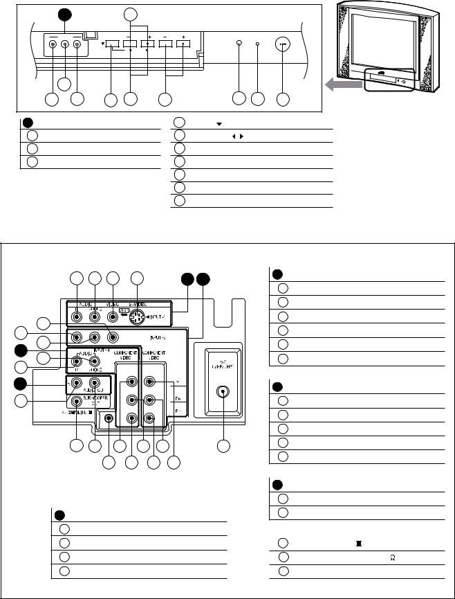
FRONT PANEL CONTROL
|
a |
|
|
6 |
|
|
|
|
|
INPUT- 3 |
|
MENU |
CHANNEL |
VOLUME |
|
ON TIMER |
|
|
|
|
|
|
|
|
|
|
|
|
|
|
|
|
|
|
POWER |
|
VIDEO L / MONO - AUDIO - R |
|
OPERATE |
|
|
|
|
|
|
|
|
|
|
|
|
||
|
2 |
|
|
|
|
|
|
|
|
1 |
3 |
4 |
5 |
7 |
8 |
9 |
10 |
a |
INPUT-3 TERMINAL |
|
4 |
MENU( ) button |
|
|
||
1 |
VIDEO |
|
|
|
5 |
OPERATE( / ) button (for MENU) |
||
2 |
AUDIO L/MONO |
|
|
6 |
CHANNEL(-/+) buttons |
|
||
3 |
AUDIO R |
|
|
|
7 |
VOLUME(-/+) buttons |
|
|
|
|
|
|
|
8 |
REMOTE CONTROL SENSOR |
||
|
|
|
|
|
9 |
POWER ON/ ON TIMER INDICATOR |
||
10 POWER SW button
REAR TERMINAL
|
4 |
3 |
2 |
1 |
|
A |
B |
B INPUT-2 TERMINAL |
|
|
|
|
|
5 |
VIDEO |
|
|
||||||
|
|
|
|
|
|
|
|
|
|
||
|
|
|
|
|
|
|
|
6 |
AUDIO L/MONO |
|
|
5 |
|
|
|
|
|
|
|
7 |
AUDIO R |
|
|
|
|
|
|
|
|
|
8 |
COMPONENT-Y |
|
|
|
7 |
|
|
|
|
|
|
|
|
|
||
6 |
|
|
|
|
|
|
|
9 |
COMPONENT-Pb |
|
|
C |
|
|
|
|
|
|
|
|
|
|
|
11 |
|
|
|
|
|
|
|
10 |
COMPONENT-Pr |
|
|
12 |
|
|
|
|
|
|
|
|
|
|
|
D |
|
|
|
|
|
|
|
C INPUT-4 TERMINAL |
|
|
|
|
|
|
|
|
|
|
|
|
|
||
17 |
|
|
|
|
|
|
|
11 |
AUDIO L/MONO |
|
|
|
|
|
|
|
|
|
|
12 |
AUDIO R |
|
|
|
|
|
|
|
|
|
|
13 |
COMPONENT-Y |
|
|
|
20 |
16 |
13 |
14 |
9 |
|
19 |
14 |
COMPONENT-Pb |
|
|
|
|
18 |
15 |
10 |
8 |
|
15 |
COMPONENT-Pr |
|
|
|
|
|
|
|
|
|
|
|||||
|
|
|
|
|
|
|
|
D AUDIO OUTPUT TERMINAL (Fixed) |
|||
|
|
|
|
|
|
|
|
16 |
AUDIO L |
|
|
A |
INPUT-1 TERMINAL |
|
|
|
17 |
AUDIO R |
|
|
|||
1 |
S-VIDEO |
|
|
|
|
|
|
|
|
|
|
2 |
VIDEO |
|
|
|
|
|
18 |
AV COMPULINK |
TERMINAL |
||
3 |
AUDIO L/MONO |
|
|
|
19 |
ANTENNA TERMINAL 75 |
(VHF/UHF) |
||||
4 |
AUDIO R |
|
|
|
|
|
20 |
SUBWOOFER OUT |
|
||
|
|
|
|
|
|
|
|
|
|
|
(No.52115)1-7 |
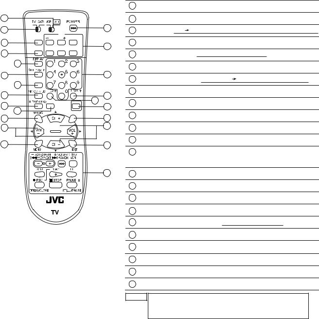
REMOTE CONTROL UNIT
22
23 |
1 |
|
|
|
PIP |
EZ SURF CHANNEL |
ON/MOVE |
|
|
2 |
|
13 |
|
INPUT SOURCE FREEZE SWAP |
|||
|
|||
3 |
|
|
|
4 |
|
|
|
5 |
|
14 |
|
SOUND |
|
|
|
6 |
|
|
|
7 |
|
15 |
|
ASPECT |
LIGHT |
16 |
|
|
|||
8 |
|
17 |
|
9 |
C.C. |
|
|
|
|
||
10 |
|
18 |
|
11 |
|
19 |
|
|
|
||
12 |
|
20 |
|
|
|
21 |
|
RM-C1250G
1POWER key
2EZ SURF key: Back program can be displayed
3 INPUT key:  TV VIDEO1
  VIDO2
VIDO2  V2-COMPONENT
 VIDEO3
  VIDEO4
4DISPLAY key
5SLEEP TIMER key:  0
0 15
15 30
30 
 165
165 180
180 
6SOUND key: AHS and BBE ON/OFF can be displayed
7 VIDEO STATUS key: 
 STANDARD DYNAMIC
  THEATER
 GAME
GAME 
8THEATER PRO key
9ASPECT key: Can be changed to 4:3 and 16:9 screen
10 MUTING key
11VOL+/- & VOL /
/ (for SERVICE MENU) keys
12MENU key
13PIP CONTROL key: (ON/MOVE, CHANNEL, SWAP, FREEZE and SOURCE keys)
Press the ON/MOVE key; PIP screen can be dispalyed
14CHANNEL NUMBER keys
15RETURN+ key
16100+ key
17LIGHT key
18C.C. (CLOSED CAPTION) key:  OFF
OFF CAPTION
 TEXT
TEXT 
19CH+/- & CH  /
/ (for SERVICE MENU) keys
20EXIT key
21VCR CONTROL key
22VCR / DVD switch
23TV / CATV switch
NOTE The CH+/- keys and VOL+/- keys operate CHANNEL and VOLUME normally.
These keys are also used to navigate SERVICE MENU as the CH /
/ and VOL
 /
/ keys.
keys.
1-8 (No.52115)
SECTION 3
DISASSEMBLY
3.1DISASSEMBLY PROCEDURE
3.1.1 REMOVING THE REAR COVER
(1)Disconnect the power plug from wall outlet.
(2)As shown in the Fig.1, remove the 11 screws [A].
(3)Withdraw the REAR COVER backward.
3.1.2REMOVING THE AV TERMINAL BOARD
• Remove the REAR COVER.
(1) As shown in Fig.1, remove the 6 screws [B].
(2) Withdraw the AV TERMINAL BOARD toward you.
3.1.3REMOVING THE CHASSIS
•Remove the REAR COVER.
•Remove the AV TERMINAL BOARD.
(1)Slightly raise the both sides of CHASSIS by hand.
(2)Remove the 2 claws under the both side of the CHASSIS from the front cabinet.
(3)Withdraw the CHASSIS backward.
(If necessary, remove the wire clamp, connectors etc.)
3.1.4 REMOVING THE SPEAKER
•Remove the REAR COVER.
(1)As shown in Fig.1, remove the 2 screws [C].
(2)Remove the 4 screws [D] and taking out the SPEAKER.
(3)Follow the same steps when removing the other hand SPEAKER.
NOTE :
When remove the 2 screws [C] of the SPEAKER, taking out the lower side screw first, and then takeing out the upper one.
3.1.5REMOVING THE LED & POWER SW PWB
• Remove the REAR COVER.
(1) Remove the 2 screws [E] as shown in Fig.1.
(2) Withdraw the LED & POWER SW PWB toward you. *If necessary, remove the wire clamp, connector etc.
3.1.6REMOVING THE FRONT CONTROL PWB
•Remove the REAR COVER.
(1)Remove the 2 screws [F] as shown in Fig.1.
(2)Withdraw the FRONT CONTROL PWB toward you. *If necessary, remove the wire clamp, connector etc.
3.1.7 CHECKING THE CHASSIS
To check the PW Board from back side.
(1)Pull out the CHASSIS (refer to REMOVING THE CHASSIS).
(2)Erect the CHASSIS vertically so that you can easily check the back side of the PW Board.
CAUTION :
•When erecting the CHASSIS, be careful so that there will be no contacting with other PW Board.
•Before turning on power, make sure that the wire connector is properly connected.
•When conducting a check with power supplied, be sure to confirm that the CRT EARTH WIRE (BRAIDED ASS'Y) is connected to the CRT SOCKET PWB.
3.1.8 WIRE CLAMPING AND CABLE TYING
(1)Be sure to clamp the wire.
(2)Never remove the cable tie used for tying the wires together. Should it be inadvertently removed, be sure to tie the wires with a new cable tie.
(No.52115)1-9

FRONT CABINET
D |
SPEAKER |
|
|
|
|
|
|
SPACER |
|
|
C |
CRT |
|
|
SOCKET |
|
SPEAKER |
PWB |
|
|
|
HOLDER |
|
|
|
|
|
FRONT |
|
|
CONTROL |
MAIN PWB |
|
PWB |
|
|
|
|
|
|
DAF PWB |
|
|
CLAW |
F |
|
HVT |
E
LED&POWER
SW PWB
TUNER
CLAW |
PIP PWB |
|
AV SELECTOR
PWB
REAR COVER
POWER CORD
AV TERMINAL BOARD
B
A
Fig.1
1-10 (No.52115)
NOTE
This exploded view describes about the AV-36FA54. You can use the exploded view for disassembling the AV-27FA54 / AV-32FA54 in the same step as for this one.
3.2REMOVING THE CRT
NOTE:
•Replacement of the CRT should be performed by 2 or more persons.
•After removing the REAR COVER, CHASSIS etc.,
(1)Putting the CRT change table on soft cloth, the CRT change table should also be covered with such soft cloth (shown in Fig. 3).
(2)While keeping the surface of CRT down, mount the TV set on the CRT change table balanced will as shown in Fig. 3.
(3)Remove 4 screws marked by arrows with a box type screwdriver as shown in Fig. 4.
NOTE:
Since the cabinet will drop when screws have been removed, be sure to support the cabinet with hands.
(4)After 4 screws have been removed, put the cabinet slowly on cloth (At this time, be carefully so as not to damage the front
surface of the cabinet) shown in Fig. 5.
NOTE:
•The CRT should be assembled according to the opposite sequence of its dismounting steps.
•The CRT change table should preferably be smaller that the CRT surface, and its height be about 35cm.
FOR AV-32FA54/AZA model only
CAUTION FOR DEGAUSSING WORKS
Whenever degaussing works are required due to d i s t o r t e d i m a g e s a n d c o l o r s c a u s e d b y t h e replacement of the CRT or other external magnetic forces, self-degaussing (internal degaussing) should be carried out without fail instead of degaussing the monitor from the outside.
Because of the characteristics of the CRT used in this monitor , the distorted images and colors may worsen if degaussing the monitor from the outside has been performed.
Even if external degaussing works have been carried out, self-degaussing should be performed by turning the power on the monitor.
When you want to perform self-degaussing of the monitor whose power is already turned on, turn of f the power and wait for about 10 minutes before turning the power on the monitor again for self-degaussing.
CRT CHANGE TABLE
APPROX.
35cm
CLOTH 
Fig.3
CRT
CRT CHANGE TABLE
BOX
TYPE
SCREW
DRIVER
Fig.4
CRT
CABINET |
CRT |
|
CHANGE TABLE |
||
|
Fig.5
(No.52115)1-11
3.3MEMORY IC REPLACEMENT
3.3.1 MEMORY IC
This TV uses memory IC.
This memory IC stores data for proper operation of the video and deflection circuits. When replacing the memory IC, be sure to use an IC containing this (initial value) data.
3.3.2 MEMORY IC REPLACEMENT PROCEDURE
1. Power off
Switch off the power and disconnect the power cord from the wall outlet.
2.Replace the memory IC
Be sure to use a memory IC written with the initial setting data.
3.Power on
Connect the power cord to the wall outlet and switch on the power.
4.Confirm the system constant value
•12.SYSTEM (SYS) do not adjust normally.
•The adjustment should not be done without signal.
How to enter the SERVICE MENU.
•Before entering the SERVICE MENU, confirm that the setting of TV/CATV SW of the REMOTE CONTROL UNIT is at the "TV" side and the setting of VCR/DVD SW of the REMOTE CONTROL UNIT is at the "VCR" side. If the switches have not been properly set, you cannot enter the SERVICE MENU.
(1)Press the [SLEEP TIMER] key and set SLEEP TIMER for "0 min".
(2)Before disappear the display of SLEEP TIMER settings, simultaneously press the [DISPLAY] key and [VIDEO STATUS] key of the remote control unit.
(3)The SERVICE MENU screen will be displayed as shown Fig.1.
How to enter the 12. SYSTEM(SYS).
(1)While the SERVICE MENU is displayed, select the 12.SYSTEM(SYS) item with [CH / ] keys, and the [VOL / ] keys is pressed, the screen will be displayed as shown in Fig.2.
(2)Refer to the "12.SYSTEM(SYS)" table and check the setting items. If the value is different, select the setting
item with the [CH / ] keys and adjust the setting with the [VOL / ] keys. (The letters of the selected item are displayed in yellow.)
(3)When adjustment has completed, the values store into memory IC automatically.
(4)Press the [EXIT] key to return the SERVICE MENU screen.
(5)Then press the [EXIT] key again to return the normal screen.
5.Receiving channel setting
Refer to the OPERATING INSTRUCTIONS (USER'S GUIDE) and set the receive channels (Channels Preset) as described.
6.User settings
Check the user setting items according to the "FACTRY SETTING VALUE" table.
Where these do not agree, refer to the OPERATING INSTRUCTIONS (USER'S GUIDE) and set the items as described.
7. SERVICE MENU setting
Verify what to set in the SERVICE MENU, and set whatever is necessary(Fig.1) .
Refer to the SERVICE ADJUSTMENT for setting.
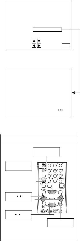
SERVICE MENU
SERVICE MENU
1.V/C(S) |
2. DEF(D) |
3.SOUND(A) |
4. OTHERS(F) |
5.PIP(PIP) |
6. 3L Y/C(LYC) |
7.LOW LIGHT |
8. HIGH LIGHT |
9.RF AFC |
10. VOC |
11.I2C BUS |
12. SYSTEM(SYS) |
SELECT BY |
|
OPERATE BY |
EXIT BY EXIT |
|
Fig.1 |
SYSTEM (SYS) MODE |
|
SYS01 VIDEO IN
|
|
Fig.2 |
|
KEY ASSIGNMENT OF REMOTE CONTROL UNIT |
|||
|
|
SLEEP TIMER key |
|
DISPLAY & |
|
||
VIDEO STATUS key |
|
||
|
|
SOUND |
|
|
|
ASPECT |
LIGHT |
|
|
|
C.C. |
VOL |
/ |
key |
|
CH |
/ |
key |
|
|
|
|
EXIT key |
|
|
|
[RM-C1250G] |
1-12 (No.52115)
Loading...