


Color Television
User’s Guide
For Models:
AV-36D800
AV-32D800
AV-27D800
Illustration of AV-27D800 and RM-C344
IMPORTANT NOTE TO THE CUSTOMER:
In the spaces below, enter the model and serial number
for your television (located on the rear of the television cabinet). Staple your sales receipt or invoice to the inside cover of this guide. Keep this user’s guide in a convenient place for future reference. Keep the carton and original packaging for future use.
Model Number |
Serial Number |

CAUTION
CAUTION:To reduce the risk of electric shock. do not remove cover (or back).
No user serviceable parts inside. Refer servicing to qualified service personnel.
The lightning flash with arrowhead symbol, within an equilateral triangle is intended to alert the user to the presence of uninsulated “dangerous voltage” within the product’s enclosure that may be of sufficient magnitude to constitute a risk of electric shock to persons.
The exclamation point within an equilateral triangle is intended to alert the user to the presence of important operating and maintenance (servicing) instructions in the literature accompanying the appliance.
IMPORTANT SAFEGUARDS
CAUTION:
Please read and retain for your safety.
Electrical energy can perform many useful functions. This TV set has been engineered and manufactured to assure your personal safety. But improper use can result in potential electrical shock or fire hazards. In order not to defeat the safeguards incorporated in this TV set, observe the following basic rules for its installation, use and servicing.
And also follow all warnings and instructions marked on your TV set.
INSTALLATION
1Your TV set is equipped with a polarized AC line plug (one blade of the plug is wider than the other).
(POLARIZED-TYPE)
This safety feature allows the plug to fit into the power outlet only one way. Should you be unable to insert the plug fully into the outlet, try reversing the plug.
Should it still fail to fit, contact your electrician.
2Operate the TV set only from a power source as indicated on the TV set or refer to the operating instructions for this information. If you are not sure of the type of power supply to your home, consult your TV set dealer or local power company. For battery operation, refer to the operating instructions.
3Overloaded AC outlets and extension cords are dangerous, and so are frayed power cords and broken plugs. They may result in a shock or fire hazard. Call your service technician for replacement.
4Do not allow anything to rest on or roll over the power cord and do not place the TV set where power cord is subject t traffic or abuse. This may result in a shock or fire hazard.
5Do not use this TV set near water — for example, near a bathtub, washbowl, kitchen sink, or laundry tub, in a wet basement, or near swimming pool, etc.
6If an outside antenna is connected to the TV set, be sure the antenna system is grounded so as to provide some protection against voltage surges and built-up static charges. Section 810 of the National Electrical Code provides information with respect to proper grounding of the mast and supporting structure, grounding of the lead-in wire to an antenna discharge
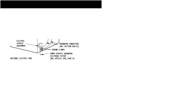
unit, size of grounding conductors, location of antenna discharge unit, connection requirements for the grounding electrode.
7An outside antenna system should not be located in the vicinity of overhead power lines or other electric light or power circuits, or where it can fall into such power lines or circuits. When installing an outside antenna system, extreme care should be taken to keep from touching such power lines or circuits as contact with them might be fatal.
8TV sets are provided with ventilation openings in the cabinet to allow heat generated during operation to be released. Therefore:
—Never block the bottom ventilation slots of a portable TV set by placing it on a bed, sofa, rug, etc.
—Never place a TV set in a “built-in” enclosure unless proper ventilation is provided.
—Never cover the openings with a cloth or other material.
—Never place the TV set near or over a radiator or heat register.
9To avoid personal injury:
—Do not place a TV set on a sloping shelf unless properly secured.
—Use only a cart or stand recommended by the TV set manufacturer.
—Do not try to roll a cart with small casters across thresholds or deep pile carpets.
—Wall or shelf mounting should follow the manufacturer’s instructions, and should use a mounting kit approved by the manufacturer.
USE
10Caution children about dropping or pushing objects into the TV set through cabinet openings. Some internal parts carry hazardous voltages and contact can result in a fire or electrical shock.
11Unplug the TV set from the wall outlet before cleaning. Do not use liquid or an aerosol cleaner.
12Never add accessories to a TV set that has not been designed for this purpose. Such additions may result in a hazard.
13For added protection of the TV set during a lightning storm or when the TV set is to be left unattended for an extended period of time, unplug it from the wall outlet and disconnect the antenna. This will prevent damage to product due to lightning storms
or power line surges.
14A TV set and cart combination should be moved with care. Quick stops, excessive force, and uneven surfaces may cause the TV set and cart combination to overturn.
SERVICE
15Unplug this TV set from the wall outlet and refer servicing to qualified service personnel under the following conditions:
A.When the power cord or plug is damaged or frayed.
B.If liquid has been spilled into the TV set.
C.If the TV set has been exposed to rain or water.
D.If the TV set does not operate normally by following the operating instructions. Adjust only those controls that are covered in the operating instructions as improper adjustment of other controls may result in damage and will often require extensive work by a qualified technician to restore the TV set to normal operation.
E.If the TV set has been dropped or damaged in any way.
F.When the TV set exhibits a distinct change in performance — this indicates a need for service.
16Do not attempt to service this TV set yourself as opening or removing covers may expose you to dangerous voltage or other hazards. Refer all servicing to qualified service personnel.
17When replacement parts are required, have the service technician verify in writing that the replacement parts he uses have the same safety characteristics as the original parts. Use of manufacturer’s specified replacement parts can prevent fire, shock, or other hazards.
18Upon completion of any service or repairs to this TV set, please ask the service technician to perform the safety check described in the manufacturer’s service literature.
19When a TV set reaches the end of its useful life, improper disposal could result in a picture tube implosion. Ask a qualified service technician to dispose of the TV set.
20Note to CATV system installer.
This reminder is provided to call the CATV system installer’s attention to Article 820-40 of the NEC that provides guidelines for proper grounding and, in particular, specifies that the cable ground shall be connected to the grounding system of the building, as close to the point of cable entry as practical.

4 T A B L E O F
CONNECTIONS
Connections Checklist . . . . . . . . . . . . . . . . 5 Front & Rear Panel Diagrams . . . . . . . . . . . . 6 Guide Plus+ Gold Setup . . . . . . . . . . . . . . . 7 Cable & Antenna Connections . . . . . . . . . . . . 7 Audio/Video Connections — Stereo . . . . . . . . . 9 Connecting to a Camcorder . . . . . . . . . . . . . 9 S-VHS Connections
(For VCR and Camcorder) . . . . . . . . . . . . 9 Connecting to a DVD Player . . . . . . . . . . . . 10 Connecting to an External Amplifier . . . . . . . . 10 Connecting to JVC AV Compu Link
Capable Components . . . . . . . . . . . . . . 11
GETTING STARTED
Remote Control . . . . . . . . . . . . . . . . . . . 12 Power . . . . . . . . . . . . . . . . . . . . . . . . . 13 Adjusting Volume . . . . . . . . . . . . . . . . . . 13 Changing Channels . . . . . . . . . . . . . . . . . 13 Setting the CATV and VCR codes . . . . . . . . . 14 The on-screen menus . . . . . . . . . . . . . . . . 16 Plug In Menu . . . . . . . . . . . . . . . . . . . . . 17
Language
Auto Tuner Setup
Guide Plus+ Gold Setup. . . . . . . . . . 18 Finish
TV GUIDE PLUS+ GOLD
Guide Plus+ Gold Setup . . . . . . . . . . . . . . 19 Introduction . . . . . . . . . . . . . . . . . . . . . 23 Grid . . . . . . . . . . . . . . . . . . . . . . . . . . 24 Sort. . . . . . . . . . . . . . . . . . . . . . . . . 26 News . . . . . . . . . . . . . . . . . . . . . . . . . 28 Schedule . . . . . . . . . . . . . . . . . . . . . . 29 Messages . . . . . . . . . . . . . . . . . . . . . . 30 Channel Editor . . . . . . . . . . . . . . . . . . . 31 Options . . . . . . . . . . . . . . . . . . . . . . . 32 V C R + . . . . . . . . . . . . . . . . . . . 3 3 Guide Plus+ Gold Buttons . . . . . . . . . . . . . 33
MENU FUNCTIONS
Initial Setup . . . . . . . . . . . . . . . . . . . . . . 34 Channel Summary . . . . . . . . . . . . . 34
Channel Guard-Lock
GUIDE Plus+ Setup
GUIDE Plus+ Demo
V-Chip . . . . . . . . . . . . . . . . . . . 35
Channel Guard Lock. . . . . . . . . . . . . 38
C O N T E N T S
Picture Adjust . . . . . . . . . . . . . . . . . . . . . 39
Tint
Color
Picture
Bright
Detail
Noise Muting Set Video Status
Sound Adjust . . . . . . . . . . . . . . . . . . . . . 40
Bass
Treble
Balance
MTS (Multi-channel Stereo Sound) Some Sound Advice
Clock/Timers . . . . . . . . . . . . . . . . . . . . . 41
Set Clock On/Off Timer
Initial Setup . . . . . . . . . . . . . . . . . . . . . . 42
TV Speaker
Audio Out Component-In Closed Caption
BUTTON FUNCTIONS
Display . . . . . . . . . . |
. . . . . . . . . . . . . |
. |
43 |
||
Video |
Status . . . . . . . |
. . . . . . . . . . . . . |
. |
43 |
|
Sleep |
Timer . . . . . . . . |
. . . . . . . . . . . . . . 43 |
|||
BBE . . . . . . . . . . . . |
. . . . . . . . . . . . . |
. |
44 |
||
Hyper |
Surround . . . . . |
. . . . . . . . . . . . . . 44 |
|||
TV/Video . . . . . . . . . |
. . . . . . . . . . . . . |
. |
44 |
||
100+ . . . . . . . . . . . . |
. . . . . . . . . . . . . . 44 |
||||
VCR Buttons . . . . . . . |
. . . . . . . . . . . . . . 44 |
||||
Muting . . . . . . . . . . . |
. . . . . . . . . . . . . |
. |
44 |
||
Return+. . . . . . . . . . . . . . . . . . . . . . . 44 |
|||||
Number |
Buttons (10 Key |
Pad) . . . . . . . . . . . |
44 |
||
On/Move |
PIP (Picture In |
Picture) . . . . . . . . . |
45 |
||
Source . . . . . . . . . . |
. . . . . . . . . . . . . . 45 |
||||
Freeze . . . . . . . . . . . |
. . . . . . . . . . . . . . 45 |
||||
Swap . . . . . . . . . . . |
. . . . . . . . . . . . . |
. |
45 |
||
Channel -/+ for PIP . . . . . . . . . . . . . . . . . . 45 Source. . . . . . . . . . . . . . . . . . . . . . . . . 45
APPENDICES
Troubleshooting . . . . . . . . . |
. . . . . . . . . . 46 |
Troubleshooting for GUIDE Plus+ |
GOLD. . . . . . 47 |
Limited Warranty. . . . . . . . . |
. . . . . . . . . . 48 |
Authorized Service Centers . . . |
. . . . . . . . . . 49 |
Specifications . . . . . . . . . . |
. . . . . . . . . . 50 |
VCR/Cable box brand lists . . . |
. . . . . . . . . . 51 |
C O N N E C T I O N S 5
CONNECTIONS CHECKLIST — READ ME FIRST!
The Connections Checklist section of this guide is a list of ideas to keep in mind when you set out to perform your connections. It is designed to help us not-so-technically-advanced individuals. If you read this section, and can’t identify the plugs, connectors, and components you have, do not be afraid to seek help.
1)Refer to the connection instructions in the user’s
guide for each component you plan to connect.
They will provide more detailed information about their products, and they will tell you what plugs and cables are required.
2)Most A/V input jacks and plugs are color coded:
•Yellow plugs are Video connections
•Red plugs are for Right Audio connections
•White plugs are Left Audio (Mono) connections
3)Perform one hookup at a time.
If you have many accessories to connect, make sure each connection is correct by checking to see that it works properly before attempting the next connection. (For example, always start with the RF or Cable connections, make sure it works, then move on to video or VCR connections.)
4)Unplug the power cord between each connection.
5)Each jack on the back of the TV is labeled. If you read these instructions and still do not fully understand the connections process, seek assistance.
6)The IR Mouse lets Guide Plus+ Gold control your cable box and/or your VCR. You must place the transmitter of the IR Mouse in front of the corresponding window on the cable box or VCR.
7)The AV Compu Link Cable is supplied with the JVC device which you want to connect. If you do not have one, but you do have a JVC Compu Link capable VCR or HiFi, contact your local JVC dealer.
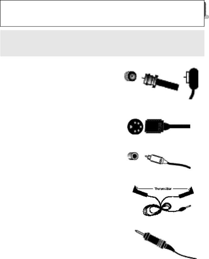
RF Connectors
S-Video Plug
A/V Input Plug
IR Mouse
AV Compu Link Cable

6 C O N N E C T I O N S
FRONT PANEL DIAGRAMS
FRONT PANEL DIAGRAM
AV-32D800 • AV-27D800
FRONT PANEL DIAGRAM
AV-36D800
REAR PANEL DIAGRAM
REAR PANEL DIAGRAM
Common to all models in this book.
C O N N E C T I O N S 7
GUIDE PLUS+ GOLD™ SETUP
CABLE & ANTENNA CONNECTIONS
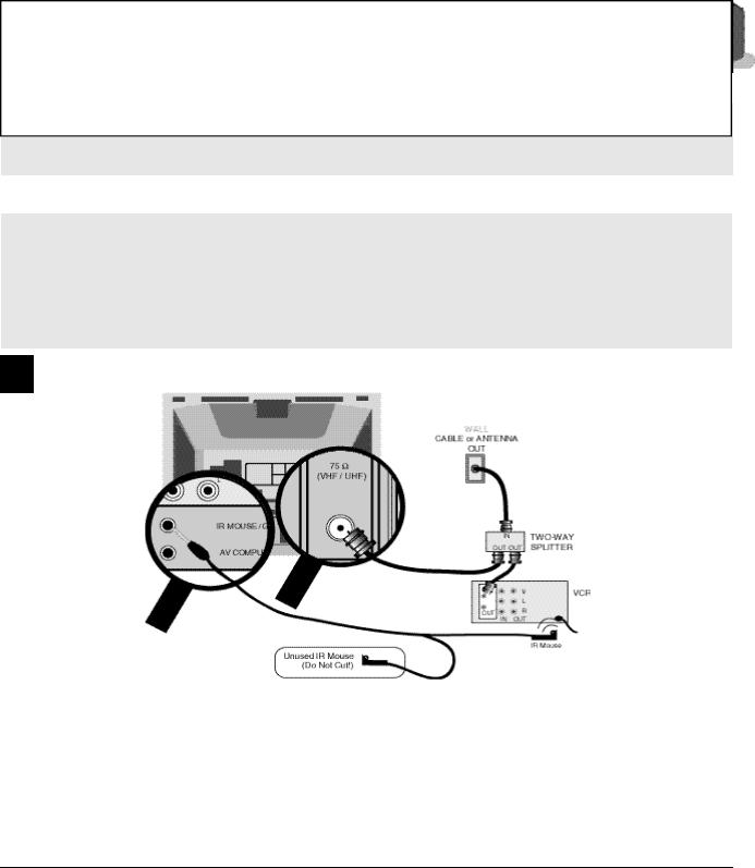
#1 No Cable Box Required
1)Connect cable or antenna wire out from wall, in to splitter RF input.
2)Connect wire out from splitter RF output, in to TV RF input.
3)Connect wire out from splitter RF output, in to VCR RF input.
NOTES: A) In order for GUIDE Plus+ GOLD to control the VCR, put one IR Mouse in front of the remote control infrared receiver window of the VCR.
B)Since this arrangement does not require you to use a cable box, DO NOT cut off the second IR Mouse. Roll up the wire, and place the second mouse behind the TV.
C)You must connect the VCR to the TV using Audio/Video connections (see page 9).
Refer to the VCR instructions regarding its connections.
VCR Plus+, C3 , PlusCode and GUIDE Plus+are trademarks of Gemstar Development Corporation. The VCR Plus+ and GUIDE Plus+ systems are manufacturred under license from Gemstar Development Corporation and VCR Index Systems B.V., respectively.
GEMSTAR IS NOT IN ANY WAY LIABLE FORTHE ACCURACY OF THE PROGRAM SCHEDULE INFORMATION PROVIDED BYTHE GUIDE PLUS+ SYSTEM. IN NO EVENT SHALL GEMSTAR BE LIABLE FOR ANY AMOUNTS REPRESENTING LOSS OF PROFITS, LOSS OF BUSINESS, OR INDIRECT, SPECIAL, OR CONSEQUENTIAL DAMAGES IN CONNECTION WITH THE PROVISION OR USE OF ANY INFORMATION, EQUIPMENT, OR SERVICES RELATINGTO THE GUIDE PLUS+ SYSTEM.
VCR required for recording.
8 C O N N E C T I O N S
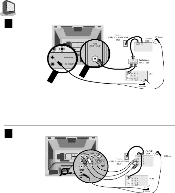
#2 Cable Box Required For All Channels
1)Connect cable wire out from the wall, in to the cable box input.
2)Connect cable wire out from cable box, in to the splitter RF input.
3)Connect cable wire out from splitter RF output, in to the TV RF input.
4)Connect cable wire out from splitter RF output, in to the VCR RF input.
NOTE: A) In order for GUIDE Plus+ GOLD to control the VCR and the cable box, put one IR Mouse in front of the remote infrared receiver window of each device.
B)You must connect the VCR to the TV using audio/video connections (see page 9).
C)When you connect cable box and VCR as shown in the above, you must set the channel of VCR to RF output of cable box after you finished GUIDE Plus+ GOLD Setup from page 19 to page 22.
#3 Cable Box Required but with Cable Box Video Output
1)Cable wire out from wall, in to cable box RF input.
2)Out from cable box RF output, in to VCR RF input.
3)Yellow video cable out from cable box Video output, in to TV Video Input 1.
4)White audio cable out from cable box Left Audio output, in to TV Left Audio input jack.
5)Red audio cable out from cable box Right Audio output, in to TV Right Audio input jack.
NOTE: A) In order for GUIDE Plus+ GOLD to control the VCR and the cable box, put one IR Mouse in front of the remote infrared receiver window of each device.
B)You must connect the VCR to the TV Video Input 2 using audio/video connections (see page 9).
C)You connect the video output from cable box to Video Input 1 of the TV. If you connect to Video Input 2, it cannot download the GUIDE Plus+ GOLD data. In the GUIDE Plus+ GOLD Setup,Step 3C, you will need to set the output of cable box to "O/AUX".
D)When you connect cable box and VCR as shown in the above, you must set the channel of VCR to RF output of cable box after you finished GUIDE Plus+ GOLD Setup from page 19 to page 22.
C O N N E C T I O N S 9
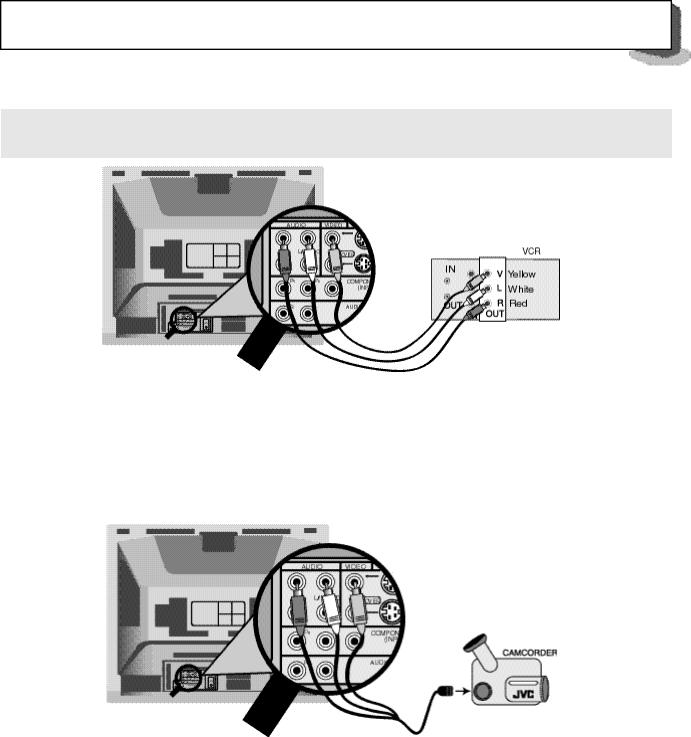
AUDIO/VIDEO CONNECTIONS — STEREO
1)Yellow video cable out from VCR, in to TV Video input jack.
2)White audio cable out from VCR Left Audio output, in to TV Left Audio input jack.
3)Red audio cable out from VCR Right Audio output, in to TV Right Audio input jack.
NOTE: If your VCR is mono, it has only one audio out jack. Connect it to the TV L/Mono input.
CONNECTING TO A CAMCORDER
1)Yellow video cable out from camcorder, in to TV Video input jack.
2)White audio cable out from camcorder, in to TV Left Audio input jack.
3)If you have a stereo model camcorder, connect the Red Audio cable out from the camcorder, in to the TV Right Audio input jack.
S-VHS CONNECTIONS (FOR VCR AND CAMCORDER)
Keep the audio connections the same as for a non-S-VHS VCR or camcorder (page 9), and use the special S-VHS cable that came with the VCR or Camcorder.
1) S-VHS Plug out from VCR, in to TV’s S-Video input.
10 C O N N E C T I O N S
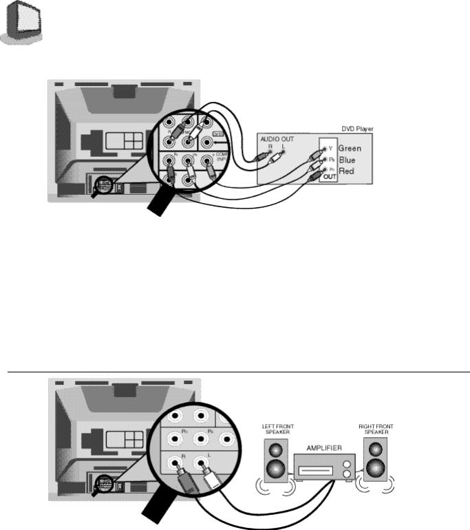
CONNECTING TO A DVD PLAYER
1)Connect green cable out from DVD player “Y” component output, in to TV “Y” component input.
2)Connect blue cable out from DVD player “PB” component output, in to TV “PB” component input.
3)Connect red cable out from DVD player “PR” component output, in to TV “PR” component input.
4)Connect white audio cable out from DVD Left audio output, in to TV Left Audio Input 2.
5)Connect red audio cable out from DVD Right audio output, in to TV Right Audio Input 2.
Green, blue and red are the most common colors of DVD cables. Some models may vary cable colors, please consult the user’s manual for your DVD player for more information.
Be careful not to confuse the red DVD cable with the red audio output cable. It is best to complete one set of connections (DVD or audio output) before starting the other to avoid accidentally switching the cables.
Please set the COMPONENT-IN on the Initial Setup Menu to "YES" whenever you connect a DVD player.
CONNECTING TO AN EXTERNAL AMPLIFIER
1)White audio cable out from TV Left Audio output jack, in to Amplifier [Left] input.
2)Red audio cable out from TV Right Audio output jack, in to Amplifier [Right] input.
NOTE: A) Set the TV Speaker to OFF (page 42), switch the audio output to VARI (page 42), and adjust the sound with the TV remote’s VOLUME button.
C O N N E C T I O N S 11
CONNECTING TO JVC AV COMPU LINK EX
CAPABLE COMPONENTS
AV Compu Link EX makes playing video tapes totally automatic. Simply insert a pre-recorded tape* into the JVC brand VCR, and the VCR automatically turns on and starts playing. At the same time, the VCR sends an AV Compu Link EX signal to the television telling it to turn on and switch to the correct video input.
NOTE: The AV Compu Link EX cable may be included with the AV Compu Link capable accessory you intend to connect. If it is not, contact an authorized JVC Service Center for Part # EWP 805-012.
NOTES:
A)The AV Compu Link EX cable has a male 3.5 mm (mono) mini plug on each end.
B)If your JVC brand VCR has A Code/B Code Remote Control Switching (see your VCR instructions), using VCR A Code will switch the TV to Video Input 1. If you use Input 1 for Video out from the cable box, use Input 2 here. Using B Code will switch the TV to Video Input 2.
C)To connect a JVC HiFi receiver or amplifier for a completely automated home theater, see the HiFi receiver's instructions for detailed hookup diagrams.
*In order for the VCR to start playback automatically, the recording tabs must be removed from the VHS tape. If the tab is in place, automatic switching starts when you push the VCR PLAY button.
**AV COMPU LINK EX is compatible with the following 1998 receivers: RX-664V, RX-665V, RX-774V, RX-884V, RX-1024V, and later receiver models.
***Please consult the user's manual for your JVC DVD Player on how to connect a JVC DVD Player using AV Compu Link EX.
12 G E T T I N G S T A R T E D
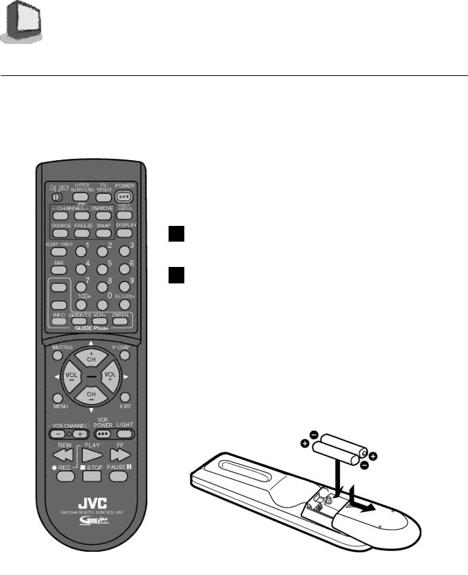
REMOTE CONTROLS
RMRM-CM344 -C344
|
CHANGING THE BATTERIES |
Be sure to use only size AA batteries. |
|
|
Push down on the remote's back cover and slide |
1 |
|
|
towards the bottom to remove it. |
2 |
Insert the two supplied AA batteries, carefully noting |
|
the “+” and “–” markings on the batteries and remote |
|
control. To avoid a short circuit, insert “–” end first. |
3 |
Slide the cover back into place (until it clicks into position). |
If the remote control acts erratically, replace the batteries. Typical battery life is usually about six months to one year.
We recommend alkaline batteries for a longer battery life.
Note:
When you change the batteries, try to complete the task in less that three minutes. If it takes longer than three minutes, the remote codes for your VCR and/or Cable box will have to be reset (page 14).

G E T T I N G S T A R T E D 13
POWER
Make sure that the TV/CATV switch is set to TV. Switch to CATV only to operate a cable box.
Press the POWER button on the remote control or the TV front panel. The On Timer lamp will glow red.
The first time you turn on the TV, the “Plug In Menu” will appear. You should turn to the Plug In Menu section (page 16) now to learn more about this menu.
To turn the power off, press the POWER button again. The On Timer lamp will go out.
When the TV is off, the OnTimer lamp remains on while the On/Off Timer function is active, but at a reduced brightness.
ADJUSTING VOLUME
1
2
CHANGING CHANNELS
1 10 key direct access.
Press the numbers on the remote’s 10 key pad. For single-digit channel numbers press 0 then the number. For channels above 100, press the 100+ button plus the 2-digit number.
2Channel +/- buttons.
•To scan the channels one at a time, press the remote's Channel + or - button and release.
•To scan through the channels very quickly, hold down the remote's Channel + or - button.
After two channels go by at normal speed, the rest of the channels will speed by at the rate of five channels per second. You will not see pictures on the channels, only the changing channel numbers at
the bottom of the screen.
3 Return.
Press and release the RETURN+ button to return to the previous channel. First, select a channel (game #1). Then, select another channel (game #2) with the 10 key pad and push the RETURN+ button to flip directly back and forth.
4 Return+ .
Press and hold down the RETURN+ button for three seconds. The message, “RETURN CHANNEL PROGRAMMED !” will appear and you can scan as you wish. Press RETURN+ again and you will go back to the Return+ channel.
To cancel a Return+ channel, press and hold down the RETURN+ button for another three seconds and the message, “RETURN CHANNEL CANCELLED !” appears.
Pressing a number key or turning the set off will also cancel a Return+ channel.

14 G E T T I N G S T A R T E D
SETTING THE CATV & VCR CODES
Many CATV & VCR brands have more than one code. If the first code in the list does not work, try the other codes listed. If your CATV box or your VCR do not respond to any of the codes listed for the manufacturer and search code function, use the remote control for that accessory to operate it.
CABLE BOX OR SATELLITE SETUP
The remote is programmed with the CATV and Satellite codes for power on and off, 10 key, and channel up and down.
1)Determine the correct code from the “CATV & Satellite Codes” chart below.
2)Slide the 2-Way Mode Selector Switch to CATV.
3)Press and hold down the DISPLAY button.
4)Enter the 3-digit code with the 10 key pad while continuing to hold down the DISPLAY button.
5)Release the DISPLAY button.
6)Confirm the operation of the cable box.
Note : If your cable box or satellite box does not respond to any code on the chart, use the Search Codes Function below.
CATV & Satellite Codes
|
CABLE BOXES |
CODES |
|
CABLE BOXES |
CODES |
|
DIGITAL |
|
CODES |
|
|
|
|
Puser |
032 |
|
SATELLITE |
|
|
|
ABC |
024 |
|
|
SYSTEMS |
|
|
||
|
Archer |
032, 025 |
|
RCA |
061 |
|
|
|
|
|
Cableview |
051, 032 |
|
Realistic |
032 |
|
Echostar |
100 |
|
|
Citizen |
022, 051 |
|
Regal |
058, 064, 040, 041, 042, 045, |
|
G.E. |
106 |
|
|
Curtis |
058, 059 |
|
|
068 |
|
Gradiente |
112 |
|
|
Diamond |
024, 032, 025 |
|
Regency |
034 |
|
Hitachi |
104, 111 |
|
|
Eagle |
029 |
|
Rembrandt |
037, 032, 051, 038 |
|
HNS(Hughes) |
104 |
|
|
Eastern |
034 |
|
Samsung |
051 |
|
Panasonic |
105 |
|
|
GCBrand |
032, 051 |
|
Scientific Atlanta 057, 058, 059 |
|
Philips |
102, 103 |
||
|
Gemini |
022, 043 |
|
SLMark |
051, 047 |
|
Primestar |
108 |
|
|
General Instrument |
065,024, 025, 026, 027, 020, |
|
Sprucer |
051, 056 |
|
RCA |
106, 109, 110 |
|
|
|
021, 022, 057, 023 |
|
Stargate |
032, 051 |
|
Sony |
107 |
|
|
Hamlin |
040, 041, 042, 045 |
|
Telecaption |
067 |
|
Toshiba |
101 |
|
|
Hitachi |
049, 024 |
|
Teleview |
047, 051 |
|
Uniden |
102, 103 |
|
|
Jerrold |
065, 024, 025, 026, 027, 020, |
|
Texscan |
044 |
|
|
|
|
|
|
021, 022, 057, 023 |
|
Tocom |
035, 036, 066 |
|
|
|
|
|
Macom |
049, 050, 051, 054 |
|
Toshiba |
050 |
|
|
|
|
|
Magnavox |
033 |
|
Unika |
032, 025 |
|
|
|
|
|
Memorex |
030 |
|
Universal |
022, 032 |
|
|
|
|
|
Movietime |
032, 051 |
|
Videoway |
052 |
|
|
|
|
|
Oak |
039, 037, 048 |
|
Viewstar |
029, 030 |
|
|
|
|
|
Panasonic |
055, 056, 060 |
|
Zenith |
063, 046 |
|
|
|
|
|
Paragon |
063 |
|
Zenith/Drake |
046 |
|
|
|
|
|
Philips |
028, 029, 030, 052, 053, 031, |
|
Satellite |
|
|
|
|
|
|
|
069 |
|
|
|
|
|
|
|
|
Pioneer |
047, 062 |
|
|
|
|
|
|
|
|
Pulsar |
051, 032 |
|
|
|
|
|
|
|
|
|
|
|
|
|
|
|
|
|
|
|
|
|
|
|
|
|
|
|
Search Codes Function :
1)Slide the 2-Way Mode Selector Switch to CATV.
2)Press the TV POWER and RETURN+ buttons simultaneously for more than three seconds, then release.
3)Press TV POWER and check if the accessory responds.
4)If there was a response, press RETURN+. If there was no response, repeat Step 3 until there is a response. If you repeat Step 3 more than 70 times and there is still no response, use the accessory remote.

G E T T I N G S T A R T E D 15
VCR SETUP
The remote is pre-programmed with the VCR codes for power on and power off, play, stop, fast-forward, rewind, pause, record, and channel up and down.
1)Determine the correct code from the “VCR Codes” chart (below).
2)Slide the 2-Way Mode Selector Switch to TV.
3)Press and hold down the DISPLAY button.
4)Enter the 3-digit code with the 10 key pad while continuing to hold down the DISPLAY button.
5)Release the DISPLAY button.
6)Confirm the operation of the VCR.
When you record a channel, press the PLAY button while continuing to hold down the REC button.
Note : If your VCR does not respond to any code on the chart, use the Search Codes Function below.
VCR Codes
VCRs |
CODES |
|
VCRs |
CODES |
|
VCRs |
CODES |
|
Admiral |
035 |
|
Magnavox |
031, 023, 024, 086 |
|
|
Samsung |
037, 060, 062, 033, 089 |
Aiwa |
027, 032 |
|
Marantz |
003, 004, 005 |
|
|
Sansui |
003, 026, 020, 052 |
Akai |
029, 072, 073, 074 |
|
Marta |
064, |
|
|
Sanyo |
063, 067, 091, 071 |
Audio Dynamic |
003, 005 |
|
Memorex |
024, 067 |
|
|
Scott |
059, 060, 062, 067, 038, 040, |
Bell & Howell |
063, 071 |
|
MGA |
038, 040, 047, 048, 041, 042 |
|
|
|
047, 048, 026, 020 |
Broksonic |
020, 026 |
|
Minolta |
058, 045 |
|
|
Sears |
063, 064, 065, 066, 058 |
Canon |
023, 025 |
|
Mitsubishi |
038, 040, 047, 048, 041, 042, |
|
|
Shintom |
075 |
CCE |
043 |
|
|
078, 090 |
|
|
Sharp |
035, 036, 080, 088 |
Citizen |
064 |
|
Multitech |
047, 027, 062 |
|
|
Signature 2000 |
027, 035 |
Craig |
063, 029, 064 |
|
NEC |
003, 004, 005, 000 |
|
|
Singer |
075 |
Curtis Mathes |
045, 024, 027 |
|
Olympic |
024, 023 |
|
|
Sony |
028, 029, 030, 053, 054, 055 |
Daewoo |
043, 059, 024 |
|
Optimus |
028, 021, 035, 064 |
|
|
SV2000 |
027 |
DBX |
003, 004, 005 |
|
Orion |
026, 020 |
|
|
Sylvania |
031, 023, 024, 027 |
Dimensia |
045 |
|
Panasonic |
023, 024, 021, 022 |
|
|
Symphonic |
027, 081 |
Emerson |
043, 026, 077, 061, 025, 042, |
|
Penney |
024, 058, 045, 063, 003, 004, |
|
|
Tashiro |
064 |
|
020, 076 |
|
|
005 |
|
|
Tatung |
003, 004, 005 |
Fisher |
063, 066, 067, 065, 071 |
|
Pentax |
058, 005, 045 |
|
|
Teac |
003, 004, 027, 005 |
Funai |
027, 026, 020, 000 |
|
Philco |
031, 024, 027, 023, 026, 020, |
|
|
Technics |
021, 022, 023, 024 |
GE |
033, 045, 024 |
|
|
043 |
|
|
Teknika |
024, 027, 070 |
Go Video |
037, 051, 049, 050, 089 |
|
Philips |
031, 023, 024, 086 |
|
|
Toshiba |
059, 046, 079 |
Goldstar |
064 |
|
Pioneer |
023 |
|
|
Vector Research |
005 |
Gradiente |
083, 084, 081, 000, 001 |
|
Proscan |
045, 058, 023,024, 031, 046, |
|
|
Wards |
035, 036, 067, 044, 064 |
Hitachi |
023, 045, 058, 027, 081 |
|
|
059, 060, 033, 087 |
|
|
Yamaha |
063, 003, 004, 005 |
Instant Replay |
024, 023 |
|
Quasar |
021, 022, 023, 024 |
|
|
Zenith |
044, 082, 064 |
Jensen |
003 |
|
Radio Shack |
033, 024, 063, 036, 067, 040, |
|
|
|
|
JVC |
000, 001, 002, 003, 004, 005 |
|
|
027 |
|
|
|
|
Kenwood |
003, 004, 064, 005 |
|
RCA |
033, 045, 058, 023, 024, 031, |
|
|
|
|
LXI |
027, 064, 058, 065, 066, 063, |
|
|
046, 059, 060, 083, 085, 087 |
|
|
|
|
|
067 |
|
Realistic |
024, 063, 036, 067, 040, 027 |
|
|
|
|
|
|
|
|
|
|
|
|
|
|
|
|
|
|
|
|
|
|
Search Codes Function :
1)Slide the 2-Way Mode Selector Switch to TV.
2)Press the VCR POWER and RETURN+ buttons simultaneously for more than three seconds, then release.
3)Press VCR POWER and check if the accessory responds.
4)If there was a response, press RETURN+. If there was no response, repeat Step 3 until there is a response. If you repeat Step 3 more than 80 times and there is still no response, use the accessory remote.
16 T H E O N S C R E E N M E N U S
THE SYMBOLS USED IN THIS GUIDE
Whenever you see up and down arrows is this book, press the MENU UP or MENU DOWN button to:
•Move vertically in the main menu,
•Move through a submenu,
•Move to the next letter, number, or other choice in a submenu, or
•Back up to correct an error, or
•Channel Up or Down
Whenever you see left and right arrows, press the
MENU LEFT or MENU RIGHT button to:
•Select the highlighted item, or
•Select the options in a submenu, or
•Volume Up or Down
The “Press Button” means you should press that button on the remote control.
The “Helping Hand” points to the highlighted or selected item in a menu.
To use the Menu, press the MENU button and then use the  and
and 
 buttons to move around the menu as described above. If you continue pressing the MENU button, the display will skip to the next menu screen.
Note: The menu screens shown in this book are representations of the menu screens on your set, not exact replications.
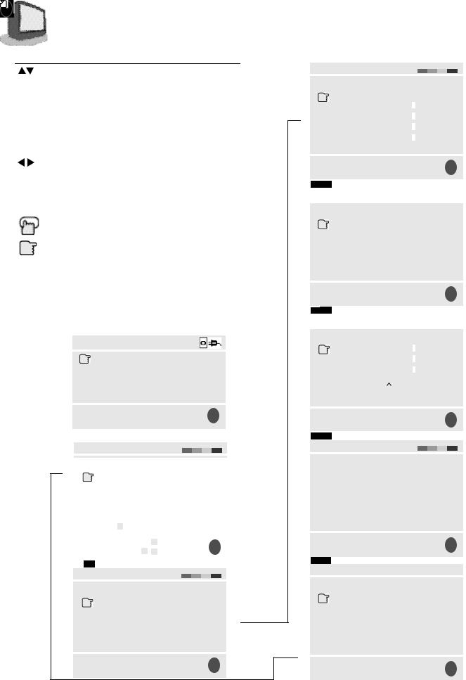
PLUG IN MENU
LANGUAGE |
ENG FRE |
SPA |
|
AUTO TUNER SETUP |
|
||
TV GUIDE PLUS+ SETUP |
|
||
FINISH |
|
|
|
SELECT |
BY |
|
EX |
OPERATE |
BY |
|
|
|
EXIT BY IT |
||
The “Plug In Menu” only appears the first time the TV is plugged in.
INITIAL SETUP
|
PREVIOUS |
|
GUIDE PLUS+ MENU |
|
|
GUIDE PLUS+ DEMO |
|
|
|
NEXT PAGE |
|
SELECT |
BY |
EX |
OPERATE |
BY |
EXIT BY IT |
INITIAL SETUP
PREVIOUS
AUTO TUNER SETUP
CHANNEL SUMMARY
V-CHIP
SET LOCK CODE
NEXT PAGE
SELECT |
BY |
EX |
OPERATE |
BY |
EXIT BY IT |
PICTURE ADJUST
|
|
PREVIOUS |
|
|
|
|
|
|
|
||
TINT |
|
------------------------- |
|
|
|
|
|
|
|
|
|
|
|
|
|
|
|
|
|
|
|
||
------------------------- |
|||||||||||
COLOR |
|||||||||||
------------------------- |
|||||||||||
PICTURE |
|||||||||||
------------------------- |
|||||||||||
BRIGHT |
|||||||||||
------------------------- |
|||||||||||
DETAIL |
|||||||||||
|
|
NEXT PAGE |
|
|
|
|
|
|
|
||
SELECT |
BY |
|
|
|
|
|
EX |
||||
OPERATE |
BY |
|
|
EXIT BY |
IT |
||||||
|
|
|
|
|
|
|
|
|
|
||
PICTURE ADJUST |
|
|
|
|
|
|
|
||||
|
|
|
|
|
|
|
|||||
|
|
|
|
|
|
|
|
|
|
|
|
|
|
PREVIOUS |
|
|
|
|
|
|
|
||
NOISE MUTING |
ON |
OFF |
|
|
|||||||
SET VIDEO STATUS |
|
|
|
|
|
|
|
||||
|
|
NEXT PAGE |
|
|
|
|
|
|
|
||
SELECT |
BY |
|
|
|
|
|
EX |
||||
OPERATE |
BY |
|
|
EXIT BY |
IT |
||||||
|
|
|
|
|
|
|
|
|
|
||
SOUND ADJUST |
|
|
|
|
|
|
|
||||
|
|
|
|
|
|
|
|||||
|
|
|
|
|
|
|
|
|
|
|
|
|
|
PREVIOUS |
|
|
|
|
|
|
|
||
BASS |
------------------------- |
||||||||||
------------------------- |
|||||||||||
TREBLE |
|||||||||||
------------------------- |
|||||||||||
BALANCE |
|||||||||||
MTS |
|
STEREO |
SAP |
MONO |
|||||||
|
ON AIR |
|
|
|
|
|
|
|
|
||
|
|
|
|
|
|
|
|
|
|
|
|
|
|
NEXT PAGE |
|
|
|
|
|
|
|
||
SELECT |
BY |
|
|
|
|
|
EX |
||||
OPERATE |
BY |
|
|
EXIT BY |
IT |
||||||
CLOCK/TIMERS
PREVIOUS
 SET CLOCK
ON/OFF TIMER
NEXT PAGE
SELECT |
BY |
|
|
|
|
|
EX |
|
OPERATE |
BY |
|
EXIT BY |
IT |
||||
INITIAL SETUP |
|
|
|
|
|
|
|
|
|
|
|
|
|
|
|
||
|
PREVIOUS |
|
|
|
|
|
|
|
TV SPEAKER |
ON |
OFF |
|
|
||||
AUDIO OUT |
VARI FIX |
|
|
|||||
COMPONENT-IN |
YES |
NO |
|
|
||||
LANGUAGE |
ENG |
FRE SPA |
|
|
||||
CLOSED CAPTION |
|
|
|
|
|
|
|
|
|
NEXT PAGE |
|
|
|
|
|
|
|
SELECT |
BY |
|
|
|
|
|
EX |
|
OPERATE |
BY |
|
EXIT BY |
IT |
||||
 Loading...