

Page 1
CORPORATE OFFICE
BS E N ISO 9001 C ertificate N o.6917
JLG INDUSTRIES, INC.
1 JLG Drive
McConnellsburg, PA 17233-9533
USA
Telephone: (717) 485-5161
Fax: (717) 485-6417
EUROPEAN OFFICE
JLG INDUSTRIES (EUROPE)
Kilmartin Place,
Tannochside Park,
Uddingston, Scotland, G71 5PH
Telephone: 01698 811005
Fax: 01698 811055
AUSTRALIAN OFFICE
JLG INDUSTRIES (AUSTRALIA)
P.0. Bo x 9 7 2
11 Bolwarra Road
Port MacQuarie
N.S.W. 44
Australia
Telephone: 1 (065) 811111
Fax: 1 (065) 81 012 2
Models
M45A
M45AJ
E45A
E45AJ
Issued: April 1, 1999 PRINTED IN U.S.A. 3120883
Updated: March 15, 2000
OPERATORS & SAFETY
Page 2

Page 3
FOREWORD
FOREWORD
The purpose of this manual is to provide users with the operating procedures essential for the promotion of
proper machine operation for its intended purpose. It is important to over-stress proper machine usage. All
information in this manual should be READ and UNDERSTOOD before any attempt is made to operate the
machine. YOUR OPERATING MANUAL IS YOUR MOST IMPORTANT TOOL - Keep it with the machine.
REMEMBER ANY EQUIPMENT IS ON LY AS SAFE AS THE OPERATOR.
BECAUSE THE MANUFACTURER HAS NO DI RECT CONTROL OVER MACHINE APPLICATION AND
OPERATION, PROPER SAFETY PRACTICES ARE THE RESPONSIBILITY OF THE USER AND HIS OPERATING PERSONNEL.
ALL INSTRUCTIONS IN THIS MANUAL ARE BASED ON THE USE OF THE MACHINE UNDER PROPER
OPERATING CONDITI ONS, WITH NO DEVIATIONS FROM THE ORIGINAL DESIGN. ALTERATION AND/OR
MODIFICATION OF THE MACHINE IS STRICTLY FORBIDDEN, WITHOUT WRITTEN APPROVAL FROM
JLG INDUSTRIES, PER OSHA REGUL ATIONS AND APPLICABLE ANSI STANDARDS.
THIS SAFETY ALERT SYMBOL IS USED TO CALL ATTENTION TO POTENTIAL HAZARDS WHICH
MAY LEAD TO SERIOUS INJURY OR DEATH IF IGNORED.
Safety of personnel and proper u se of the mac hine are of pr imary conc ern, DANGER, WARNIN G, CAUTION, IMPORTANT, INST RUCTIONS an d NOTE are inserted thr oughout this manual to e mphasize these
areas. They are defined as follows :
DANGER INDICATES AN IMMINENTLY HAZARDOUS SITUATION
WHICH, IF NOT AVOIDED WILL RESULT IN SERIOUS INJURY OR
DEATH.]
CAUTION INDICATES A POTENTIALLY HAZARDOUS SITUATION
WHICH, IF NOT AVOIDED, MAY RESULT IN MINOR OR MODERATE
INJURY. IT MAY ALSO BE USED TO ALERT AGAINST UNSAFE
PRACTICES
JLG INDUSTRIES MAY HAVE ISSUED SAFETY RELATED BULLETINS FOR YOUR JLG PRODUCT. CONTACT JLG INDUSTRIES INC.
OR THE LOCAL AUTHOR IZED JLG DISTRIBUTO R FOR INFORMATION CONCERNING SAFETY RELATED BULLETINS WHICH MAY
HAVE BEEN ISSUED FOR YOUR JLG PRODUCT. ALL ITEMS REQUIRED BY THE SAFETY RELATED BULLETINS MUST BE COMPLETED ON THE AFFECTED JLG PRODUCT
WARNING INDICATES A POTENTIALLY HAZARDOUS SITUATION
WHICH, IF NOT AVOIDED COULD RESULT IN SERIOUS INJURY
OR DEATH.
IMPORTANT OR INSTRUCTIONS INDICATES A PROCEDURES
ESSENTIAL FOR SAFE OPERATION AND WHICH, IF NOT FOLLOWED, MAY RESULT IN A MALFUNCTION OR DAMAG E TO THE
MACHINE.
Due to continuous product improvements, JLG Industries, Inc. reserves the right to make specification changes without prior notification. Contact JLG Industries, Inc. for updated information.
3120883 – JLG Lift – a
Page 4

FOREWORD
This page left blank intentionally.
b – JLG Lift – 3120883
Page 5

FOREWORD
All procedures herein are based on the use of the
machine under proper operating conditions, with no
deviation s fr om or igin al desi gn i nte nt. .. as p er OSHA
regulations.
READ & HEED!
The ownership, use, service, and/or maintenance of
this machine is subject to various governmental and
local laws and regu la tio ns. It is th e re sp ons ibil it y of
the owner/user to be knowledgeable of these laws
and regulations and to comply with them. The most
prevalent regulations of this type in the United States
are the Federal OSHA Safety Regulation s*. Listed
below, in abbreviated form are some of the requirements of Federal OSHA regulations in effect as of the
date of publication of this handbook.
The listing of these requirements shall not relieve
the owner/user of the responsibility and obligation
to determine all applicable laws and regulations and
their exact wording and re quirements, and t o comply with the requirements. Nor shall the listing of
these requirements constitute an assumption of
responsibility of liability on the part of JLG Industries, Inc.
1. Only trained and authoriz ed operat ors shall be
permitted to operate the aerial lift.
2. A malfunctioning lift shall be shut down until
repaired.
3. The controls shall be plainly marked as to their
function.
4. The controls shall be tested each day prior to
use to determ in e that they are in safe operat in g
condition.
5. All personnel in the platform shall, at all times,
wear approved fall protection devices and
other safety gear as required.
6. Load limits specified by the manufacturer shall
not be exceeded.
7. Instruction and warning placards must be legible.
8. Aerial lifts may be field modified for uses other
than those in te nd ed by the manufa cturer only if
certified in writ ing by the m anufac turer to be i n
conformity to JLG requirements and to be at
least as safe as it was prior to modification.
9. Aerial lifts shall not be used near electric power
lines unless the lines have been de energized
or adequate clearance is maintained.
10. Employees using aeri al lifts shall be instructed
on how to rec ognize and avoid un safe conditions and hazards.
11. Ground controls shall not be operated unless
permission has be en obtained fro m personnel
in the platform, except in case of an emergency.
12. Regular inspection of the job site and aerial lift
shall be performed by competen t persons.
13. Person n el sha ll always stand on the floor of the
platform, not on b oxes, planks, railing or oth er
devices, for a work position.
*Applicable Federal OSHA regulations for the
United States, as of the date of publicat ion of this
manual, include, but are not limited to, 29 CFR
1910.67, 29 CFR 1926.20, 29 CFR 1926.21, 29 CFR
1926.28, and 29 CFR 1926.453.
3120883 – JLG Lift – c
Page 6

FOREWORD
REVISON LOG
April 1, 1999 - Original Issue
3-9 - Updated 5-7-99
3-9 - Updated 5-12-99
2-5 - Updated 5-21-99
4-3 - Updated 5-21-99
2-10 & 2-11 - Updated 6-1-99
3-10 thru 3-12 - Updated 6-1-99
6-1 - Updated 6-1-99
3-7 - Updated 7-13-99
3-13 - Updated 7-13-99
2-11 - Updated 8-4-99
4-1 - Updated 8-4-99
4-5 thru 4-7 - Updated 8-4-99
3-5 thru 3-8 - Updated 8-18-99
4-7 - Updated 9-21-99
2-9 - Updated 11-3-99
2-11 - Updated 11-3-99
5-1 - Updated 11-3-99
6-1 - Updated 12-1-99
4-1 - Updated 3-15-00
4-8 - Updated 3-15-00
d – JLG Lift – 3120883
Page 7

TABLE OF CONTENTS
TABLE OF CONTENTS
SUBJECT - SECTION, PARAGRAPH PAGE NO.
SECTION - FOREWORD
SECTION 1 - SAFE TY PRECAUTIONS
1.1 General . . . . . . . . . . . . . . . . . . . . . . . . . . . . . . . . . . . . . . . . . . . . . . . . . . . . . . . . . . . . . . . . . . . . . .1-1
1.2 Driving/Towing. . . . . . . . . . . . . . . . . . . . . . . . . . . . . . . . . . . . . . . . . . . . . . . . . . . . . . . . . . . . . . . . .1-1
1.3 Electrocution Hazard. . . . . . . . . . . . . . . . . . . . . . . . . . . . . . . . . . . . . . . . . . . . . . . . . . . . . . . . . . . .1-2
1.4 Pre-Operational. . . . . . . . . . . . . . . . . . . . . . . . . . . . . . . . . . . . . . . . . . . . . . . . . . . . . . . . . . . . . . . .1-2
1.5 Driving . . . . . . . . . . . . . . . . . . . . . . . . . . . . . . . . . . . . . . . . . . . . . . . . . . . . . . . . . . . . . . . . . . . . . . .1-4
1.6 Operation. . . . . . . . . . . . . . . . . . . . . . . . . . . . . . . . . . . . . . . . . . . . . . . . . . . . . . . . . . . . . . . . . . . . .1-5
1.7 Towing and Hauling . . . . . . . . . . . . . . . . . . . . . . . . . . . . . . . . . . . . . . . . . . . . . . . . . . . . . . . . . . . .1-8
SECTION 2 - PREPAR ATI ON AND INSPECTION
2.1 General . . . . . . . . . . . . . . . . . . . . . . . . . . . . . . . . . . . . . . . . . . . . . . . . . . . . . . . . . . . . . . . . . . . . . .2-1
2.2 Preparation For Use . . . . . . . . . . . . . . . . . . . . . . . . . . . . . . . . . . . . . . . . . . . . . . . . . . . . . . . . . . . .2-1
2.3 Delivery and Frequent Inspection. . . . . . . . . . . . . . . . . . . . . . . . . . . . . . . . . . . . . . . . . . . . . . . . . .2-1
2.4 Daily Walk-around Inspection. . . . . . . . . . . . . . . . . . . . . . . . . . . . . . . . . . . . . . . . . . . . . . . . . . . . .2-4
2.5 Daily Functional Check . . . . . . . . . . . . . . . . . . . . . . . . . . . . . . . . . . . . . . . . . . . . . . . . . . . . . . . . . .2-4
2.6 Torque Requirements . . . . . . . . . . . . . . . . . . . . . . . . . . . . . . . . . . . . . . . . . . . . . . . . . . . . . . . . . . .2-5
2.7 Battery Maintenance and Charging . . . . . . . . . . . . . . . . . . . . . . . . . . . . . . . . . . . . . . . . . . . . . . . .2-8
SECTION 3 - USER RESPONSIBILITIES AND MACHINE CONTROL
3.1 General . . . . . . . . . . . . . . . . . . . . . . . . . . . . . . . . . . . . . . . . . . . . . . . . . . . . . . . . . . . . . . . . . . . . . .3-1
3.2 Personnel Training . . . . . . . . . . . . . . . . . . . . . . . . . . . . . . . . . . . . . . . . . . . . . . . . . . . . . . . . . . . . .3-1
3.3 Operating Characteristics and Limitations . . . . . . . . . . . . . . . . . . . . . . . . . . . . . . . . . . . . . . . . . . .3-2
3.4 Controls and Indicators. . . . . . . . . . . . . . . . . . . . . . . . . . . . . . . . . . . . . . . . . . . . . . . . . . . . . . . . . .3-2
SECTION 4 - MACHINE OPERATION
4.1 Description . . . . . . . . . . . . . . . . . . . . . . . . . . . . . . . . . . . . . . . . . . . . . . . . . . . . . . . . . . . . . . . . . . .4-1
4.2 General . . . . . . . . . . . . . . . . . . . . . . . . . . . . . . . . . . . . . . . . . . . . . . . . . . . . . . . . . . . . . . . . . . . . . .4-1
4.3 Motor Operation . . . . . . . . . . . . . . . . . . . . . . . . . . . . . . . . . . . . . . . . . . . . . . . . . . . . . . . . . . . . . . .4-1
4.4 Traveling (Driving). . . . . . . . . . . . . . . . . . . . . . . . . . . . . . . . . . . . . . . . . . . . . . . . . . . . . . . . . . . . . .4-2
4.5 Steering . . . . . . . . . . . . . . . . . . . . . . . . . . . . . . . . . . . . . . . . . . . . . . . . . . . . . . . . . . . . . . . . . . . . . .4-2
4.6 Platform . . . . . . . . . . . . . . . . . . . . . . . . . . . . . . . . . . . . . . . . . . . . . . . . . . . . . . . . . . . . . . . . . . . . . .4-2
4.7 Boom . . . . . . . . . . . . . . . . . . . . . . . . . . . . . . . . . . . . . . . . . . . . . . . . . . . . . . . . . . . . . . . . . . . . . . . .4-3
4.8 Generator. . . . . . . . . . . . . . . . . . . . . . . . . . . . . . . . . . . . . . . . . . . . . . . . . . . . . . . . . . . . . . . . . . . . .4-4
4.9 Machine Function Speeds . . . . . . . . . . . . . . . . . . . . . . . . . . . . . . . . . . . . . . . . . . . . . . . . . . . . . . .4-4
4.10 Shut Down and Park. . . . . . . . . . . . . . . . . . . . . . . . . . . . . . . . . . . . . . . . . . . . . . . . . . . . . . . . . . . .4-4
4.11 Machine Lifting and Tie Down. . . . . . . . . . . . . . . . . . . . . . . . . . . . . . . . . . . . . . . . . . . . . . . . . . . . .4-5
4.12 Boom Synchronizing Procedure. . . . . . . . . . . . . . . . . . . . . . . . . . . . . . . . . . . . . . . . . . . . . . . . . . .4-5
SECTION 5 - OPTIONAL EQUIPMENT
5.1 Motion Alarm . . . . . . . . . . . . . . . . . . . . . . . . . . . . . . . . . . . . . . . . . . . . . . . . . . . . . . . . . . . . . . . . . .5-1
5.2 Foam Filled Tires. . . . . . . . . . . . . . . . . . . . . . . . . . . . . . . . . . . . . . . . . . . . . . . . . . . . . . . . . . . . . . .5-1
5.3 Non-marking Tires. . . . . . . . . . . . . . . . . . . . . . . . . . . . . . . . . . . . . . . . . . . . . . . . . . . . . . . . . . . . . .5-1
5.4 Rotating Beacon . . . . . . . . . . . . . . . . . . . . . . . . . . . . . . . . . . . . . . . . . . . . . . . . . . . . . . . . . . . . . . .5-1
5.5 Tilt Alarm . . . . . . . . . . . . . . . . . . . . . . . . . . . . . . . . . . . . . . . . . . . . . . . . . . . . . . . . . . . . . . . . . . . . .5-1
5.6 Wheel Covers . . . . . . . . . . . . . . . . . . . . . . . . . . . . . . . . . . . . . . . . . . . . . . . . . . . . . . . . . . . . . . . . .5-1
5.7 Battery Packs. . . . . . . . . . . . . . . . . . . . . . . . . . . . . . . . . . . . . . . . . . . . . . . . . . . . . . . . . . . . . . . . . .5-1
5.8 Platform Light s. . . . . . . . . . . . . . . . . . . . . . . . . . . . . . . . . . . . . . . . . . . . . . . . . . . . . . . . . . . . . . . . .5-1
5.9 Control Console Cover . . . . . . . . . . . . . . . . . . . . . . . . . . . . . . . . . . . . . . . . . . . . . . . . . . . . . . . . . .5-1
5.10 Cylinder Bellows . . . . . . . . . . . . . . . . . . . . . . . . . . . . . . . . . . . . . . . . . . . . . . . . . . . . . . . . . . . . . . .5-1
5.11 Work Platform . . . . . . . . . . . . . . . . . . . . . . . . . . . . . . . . . . . . . . . . . . . . . . . . . . . . . . . . . . . . . . . . .5-1
3120883 – JLG Lift – i
Page 8

TABLE OF CONTENTS
(Continued)
TABLE OF CONTENTS (continued)
SUBJECT - SECTION, PARAGRAPH PAGE NO.
SECTION 6 - EMERGENCY PROCEDURES
6.1 General . . . . . . . . . . . . . . . . . . . . . . . . . . . . . . . . . . . . . . . . . . . . . . . . . . . . . . . . . . . . . . . . . . . . . .6-1
6.2 Emergency Towing Procedures . . . . . . . . . . . . . . . . . . . . . . . . . . . . . . . . . . . . . . . . . . . . . . . . . . .6-1
6.3 Emergency Cont rols and Their Locat ions . . . . . . . . . . . . . . . . . . . . . . . . . . . . . . . . . . . . . . . . . . .6-1
6.4 Emergency Ope ra t ion. . . . . . . . . . . . . . . . . . . . . . . . . . . . . . . . . . . . . . . . . . . . . . . . . . . . . . . . . . .6-2
6.5 Incident Notification. . . . . . . . . . . . . . . . . . . . . . . . . . . . . . . . . . . . . . . . . . . . . . . . . . . . . . . . . . . . .6-2
SECTION 7 - INSPEC TION AND REPAIR LOG
LIST OF FIGURES
FIGURE NO. TITLE PAGE NO.
2-1. Basic Nomenclature . . . . . . . . . . . . . . . . . . . . . . . . . . . . . . . . . . . . . . . . . . . . . . . . . . . . . . . . . . . .2-3
2-2. Daily Walk-Around Inspection. . . . . . . . . . . . . . . . . . . . . . . . . . . . . . . . . . . . . . . . . . . . . . . . . . . . .2-6
2-3. Lubrication Chart. . . . . . . . . . . . . . . . . . . . . . . . . . . . . . . . . . . . . . . . . . . . . . . . . . . . . . . . . . . . . . .2-10
2-4. Torque Chart. . . . . . . . . . . . . . . . . . . . . . . . . . . . . . . . . . . . . . . . . . . . . . . . . . . . . . . . . . . . . . . . . .2-12
3-1. Position of Least Forward Stability . . . . . . . . . . . . . . . . . . . . . . . . . . . . . . . . . . . . . . . . . . . . . . . . .3-3
3-2. Position of Least Backward Stability. . . . . . . . . . . . . . . . . . . . . . . . . . . . . . . . . . . . . . . . . . . . . . . .3-4
3-3. Ground Control Station. . . . . . . . . . . . . . . . . . . . . . . . . . . . . . . . . . . . . . . . . . . . . . . . . . . . . . . . . .3-5
3-4. Platform Console. . . . . . . . . . . . . . . . . . . . . . . . . . . . . . . . . . . . . . . . . . . . . . . . . . . . . . . . . . . . . . .3-7
3-5. Caution, Danger, Warning Decal Location. . . . . . . . . . . . . . . . . . . . . . . . . . . . . . . . . . . . . . . . . . .3-10
3-6. Control Panel Symbols (Sheet 1 of 2) . . . . . . . . . . . . . . . . . . . . . . . . . . . . . . . . . . . . . . . . . . . . . .3-13
3-7. Control Panel Symbols (Sheet 2 of 2) . . . . . . . . . . . . . . . . . . . . . . . . . . . . . . . . . . . . . . . . . . . . . .3-14
4-1. Grade and Side Sl opes. . . . . . . . . . . . . . . . . . . . . . . . . . . . . . . . . . . . . . . . . . . . . . . . . . . . . . . . . .4-3
4-2. Upright Positioning . . . . . . . . . . . . . . . . . . . . . . . . . . . . . . . . . . . . . . . . . . . . . . . . . . . . . . . . . . . . .4-6
4-3. Lifting Chart. . . . . . . . . . . . . . . . . . . . . . . . . . . . . . . . . . . . . . . . . . . . . . . . . . . . . . . . . . . . . . . . . . .4-7
4-4. Chassis & Platform Tie Down . . . . . . . . . . . . . . . . . . . . . . . . . . . . . . . . . . . . . . . . . . . . . . . . . . . . .4-8
LIST OF TABLES
TABLE NO. TITLE PAGE NO.
1-1 M inimum Safe Approach Dis t anc e s (M .S.A.D.) to energi ze d (exposed or insulated)
power lines and parts . . . . . . . . . . . . . . . . . . . . . . . . . . . . . . . . . . . . . . . . . . . . . . . . . . . . . .1-2
2-1 Lubrication Chart. . . . . . . . . . . . . . . . . . . . . . . . . . . . . . . . . . . . . . . . . . . . . . . . . . . . . . . . . . . . . . .2-11
3-1 Simultaneous Functions . . . . . . . . . . . . . . . . . . . . . . . . . . . . . . . . . . . . . . . . . . . . . . . . . . . . . . . . .3-9
7-1 Inspection and Repair Log . . . . . . . . . . . . . . . . . . . . . . . . . . . . . . . . . . . . . . . . . . . . . . . . . . . . . . .7-1
ii – JLG Lift – 3120883
Page 9

SECTION 1 - SAFETY PRECAUTIONS
SECTION 1. SAFETY PRECAUTIONS
1.1 GENERAL
This section prescribes the prope r and safe practices for
major areas of machine usage. In order to promote proper
usage of the machine, it is mandatory that a daily routine
be establish ed based on instructions given in thi s s e ction.
A maintenance pr ogram must also be establishe d by a
qualified person and must be follow ed to ensure that the
machine is safe to operate.
The owner/user/operator of the machine should not
accept operating responsibility until this manual has been
read and understood, and operation of the machine,
under the supervisio n of an exper ienced and qualif ied person, has been completed. If there is a question on application and/or op eration, JLG Industri es Inc., sho uld be
consulted.
MODIFICATION OR ALTERATION OF AN AERIAL PLATFORM
SHALL BE MADE ONLY WITH PRIOR WRITTEN PERMISSION OF
THE MANUFACTURER.
1.2 DRIVING/TOWING
Before driving the machine, the user must be familiar with
the drive, steer and stopping characteristics. This is especially important when driving in close quarters.
The user should be familiar with the driving surface before
driving. The surface s hould be firm and level and grade s
should not exceed the allowable grade for the machine.
NOTE: Remember that the key to safe and proper usage is
common sense and its careful application.
The machine is not equipped with provisions for towing.
Refer to Section 6 for emergency towing procedures.
SPECIAL NOTE:
FAILURE TO COMPLY WITH SAFETY PRECAUTIONS LISTED IN
THIS SECTION AND ON THE MACHINE COULD RESULT IN
MACHINE DAMAGE, PERSONNEL INJURY OR DEATH, AND IS A
SAFETY VIOLATION.
3120883 – JLG Lift – 1-1
Page 10
SECTION 1 - SAFETY PRECAUTIONS
Table 1-1. Minimum Safe Approach Distances (M.S.A.D.) to energized (exposed or insulated) power lines and parts
Voltage Range
(Phase to Phase)
0 to 300V AVOID CONTACT
Over 300V to 50 KV 3
Over 50KV to 200 KV 5
Over 200 KV to 350 KV 6
Over 350 KV to 500 KV 8
Over 500 KV to 750 KV 11
Over 750 KV to 1000 KV 14
DANGER: DO NOT maneuver machine or personnel inside PROHIBITED ZONE. ASSUME all electrical parts and wiring
are ENERGIZED unless known otherwise.
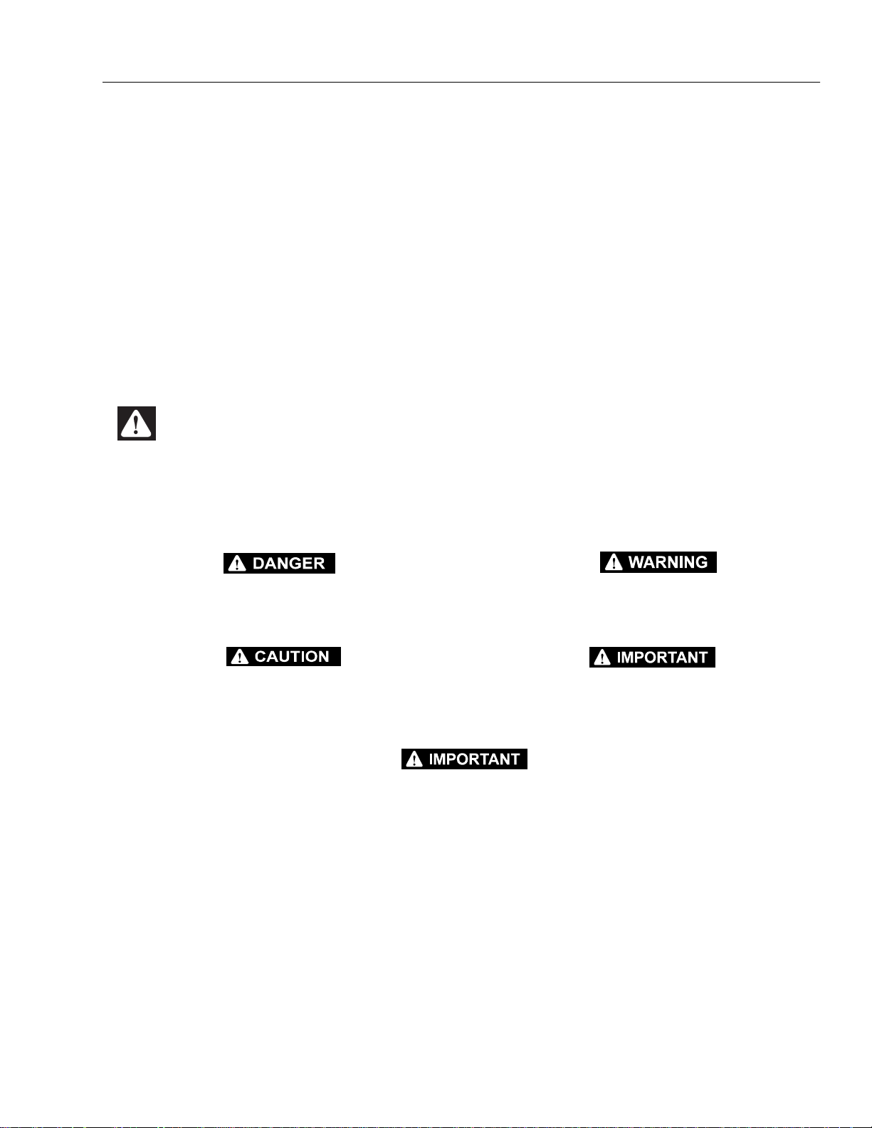
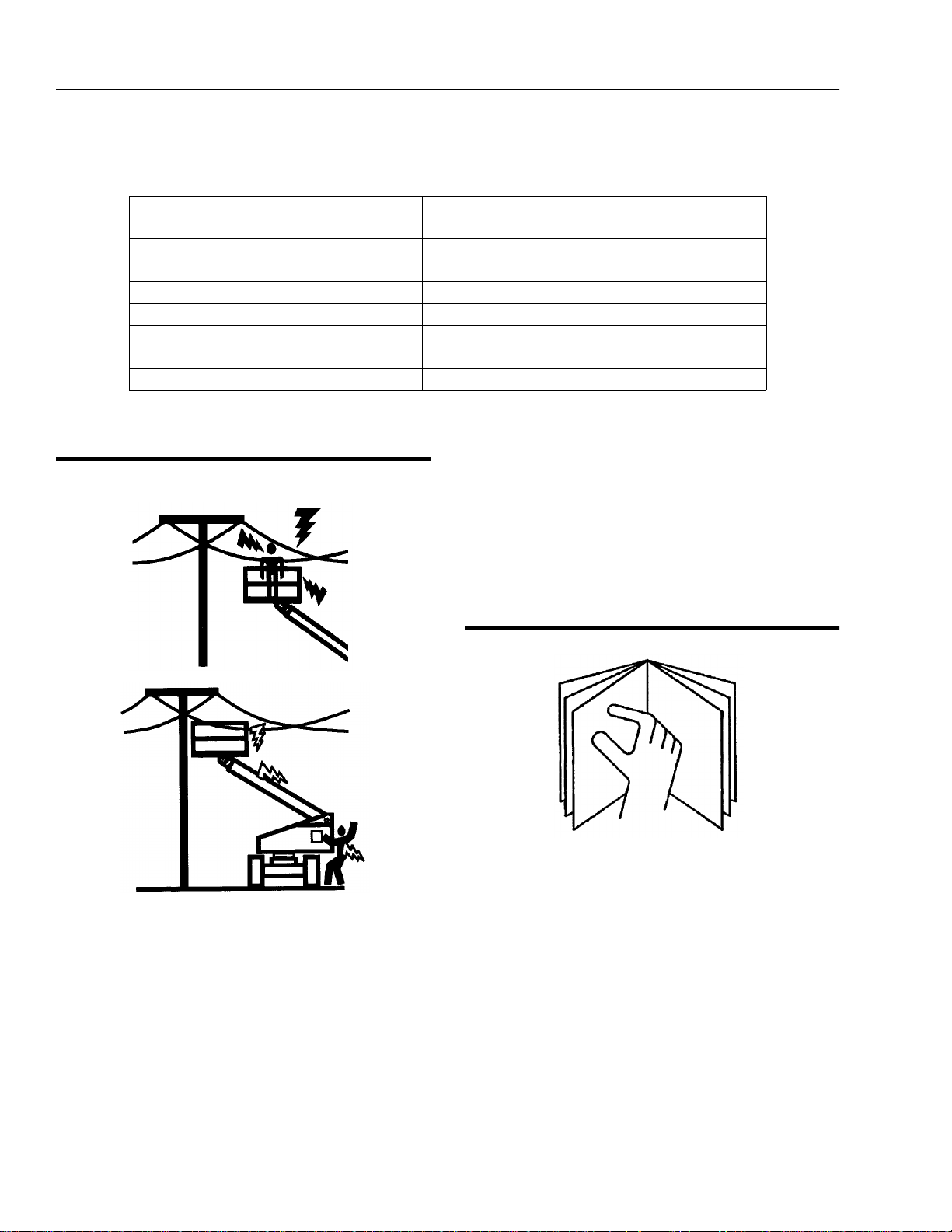
1.3 ELECTROCUTION HAZARD
MINIMUM SAFE APPROACH DISTANCE
in Meters
FROM CONTACT WITH OR PROXIMITY TO AN ELECTRICALLY CHARGED CONDUCTOR.
• MAINTAIN A CLEARANCE OF AT LEAST 3 M (10
FEET) BETWEEN ANY PART OF THE MACHINE OR
ITS LOAD AND ANY ELECTRICAL LINE OR APPARATUS CARRYING UP TO 50,000 VOLTS. 30.5 cm ADDITIONAL CLEARANCE IS REQUIRED FOR EVERY
ADDITIONAL 30,000 VOLT S OR LESS.
1.4 PRE-OPERATIONAL
• R EAD YOUR MANUAL. UNDERSTAND WHAT YOU’VE
READ - THEN BEGIN OPERATIONS.
• MAINTAIN SAFE CLEARANCE FROM ELECTRICAL
LINES AND APPARATUS. ALLOW FOR BOOM SWAY,
ROCK OR SAG AND ELECTRICAL LINE SWAYING.
THE MACHINE DOES NOT PROVIDE PROTECTION
• ALLOW ONLY AUTHORIZED AND QUALIFIED PERSONNEL TO OPERATE MACHINE W HO HAVE DEMONSTRATED THAT THEY UNDERSTAND SAFE AND
PROPER OPERATION AND MAINTENANCE OF THE
UNIT.
1-2 – JLG Lift – 3120883
Page 11
SECTION 1 - SAFETY PRECAUTIONS
• AN OPERATOR MUST NOT ACCEPT OPERATING
RESPONSIBILITIES UNTIL ADEQUA TE TRAINING HAS
BEEN GIVEN BY COMPETENT AND AUTHORIZED
PERSONS.
• BEFORE OPERATION, CHECK WORK AREA FOR
OVERHEAD ELECTRIC LINES, MACHINE TRAFFIC
SUCH AS BRIDGE CRANES , HIGH W AY, RAILWAY AND
CONSTRUCTION EQUIPMENT.
• NEVER DISABLE OR MODIFY THE FOOTSWITCH OR
ANY OTHER SAFETY DEVICE. UNAUTHORIZED MODIFICATION OF THE MACHINE IS A SAFETY VIOLATION.
• PRECAUTIONS TO AVOID ALL KNOWN HAZARDS IN
THE WORK AREA MUST BE TAKEN BY THE OPERATOR AND HIS SUPERVISOR BEFORE STARTING THE
WORK.
• DO NOT OPERATE THIS MACHINE UNLESS IT HAS
BEEN SERVICED AND MAINTAINED ACCORDING TO
THE MANUFACTURERS SPECIFICATIONS AND
SCHEDULE.
• ENSURE DAILY INSPECTION AND FUNC TION CHEC K
IS PERFORMED PRIOR TO PLACING MACHINE INTO
OPERATION.
• DO NOT OPERATE MACHINE WHEN WIND CONDITIONS EXCEED 12.5 M/S (30MPH).
• NEVER OPERATE BOOM FUNCTIONS (TELE, SWING,
LIFT) WHEN MACHINE IS ON A TRUCK, OTHER VEHICLE, OR ABOVE GROUND STRUCTURE.
• THIS MACHINE CAN BE OPERATED IN NOMINAL
AMBIENT TEMPERATURES OF -20° C TO 40° C (0° F
TO 104°F). CONSULT FACTORY TO OPTIMIZE
OPERATION OUTSIDE THIS RANGE.
• APPROVED HEAD GEAR MUST BE WORN BY ALL
OPERATING AND GROUND PERSONNEL.
3120883 – JLG Lift – 1-3
Page 12
SECTION 1 - SAFETY PRECAUTIONS
.
• R EAD AND OBEY ALL DANGERS, WARNINGS, CAUTIONS AND OPERATING INSTRUCTIONS ON
MACHINE AND IN THIS MANUAL.
• BE FAMILIAR WITH LOCATION AND OPERATION OF
GROUND STATION CONTROLS.
• ALWAYS POSITION BOOM OVER REAR (DRIVE) AXLE
IN LINE WITH DIRECTION OF TRAVEL. REMEMBER,
IF BOOM IS OVER FRONT (STEER) AXLE, DIRECTION
OF STEER AND DRIVE MOVEMENT WILL BE OPPOSITE FROM NORMAL OPERATION.
• ALWAYS USE THREE POINT CONTACT WHEN
ENTERING OR EXITING THE MAC HINE. FACE THE
MACHINE WHEN YOU ENTER OR LEAVE. THREE
POINT CONTACT MEANS THAT TWO HANDS AND
ONE FOOT OR O NE HAND AN D TWO F EET ARE IN
CONTACT WITH THE MACHINE AT ALL TIMES DURING MOUNT AND DISMOUNT.
1.5 DRIVING
• WATCH FOR OBSTRUCTIONS AROUND MACHINE
AND OVERHEAD WHEN DRIVING.
• DO NOT USE DRIVE FUNCTION TO POSITION PLATFORM CLOSE TO OBSTACLES. USE BOOM FUNCTION INSTEAD.
• WHEN DRIVING IN HIGH SPEED, SWITCH TO LOW
SPEED BEFORE STOPPING. TRAVEL GRADES IN
LOW DRIVE, HIGH ENGINE ONLY.
• DO NOT USE HIGH SPEED DRIVE WHEN IN
RESTRICTED OR CLOSE QUARTERS, OR WHEN
DRIVING IN REVERSE.
• BE AWARE OF STOPPING DISTANCES WHEN TR AVELING IN HIGH AND LOW SPEEDS.
• ALWAYS POST A LOOKOUT AND SOUND HORN
WHEN DRIVING IN AREAS WHERE VISION IS
OBSTRUCTED.
• KEEP NON-OPERATING PERSONNEL AT LEAST 2 M
(6 FEET) AWAY FROM MACHINE DURING DRIVING
OPERATIONS.
1-4 – JLG Lift – 3120883
Page 13
SECTION 1 - SAFETY PRECAUTIONS
1.6 OPERATION.
• R EAD YOUR MANUAL. UNDERSTAND WHAT YOU’VE
READ - THEN BEGIN OPERATIONS.
• CHECK TRAVEL PATH FOR PERSONS, HOLES,
BUMPS, DROP-OFFS, OBSTRUCTIONS, DEBRIS,
AND COVERINGS WHICH MAY CONCEAL HOLES
AND OTHER HAZARDS.
• TRAVEL IS PERMITTED ON GRADES NO GREATER
THAN THOSE INDICATED ON THE SERIAL NUMBER
PLATE.
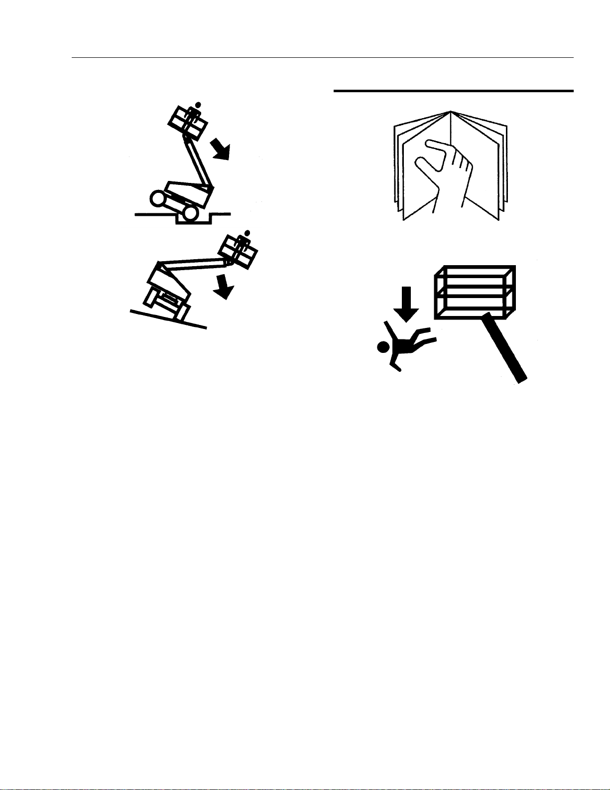
• DO NOT DRIVE ON SIDESLOPES WHICH EXCEED 5°.
• DO NOT TRAVEL ON SOFT OR UNEVEN SURFACES,
AS TIPPING WILL OCCUR.
• DO NOT DRIVE MACHINE NEAR PITS, LOADING
DOCKS OR OTHER DROP-OFFS.
• PRIOR TO ENTERING AND EXITING PLATFORM AT
GROUND LEVEL, FULLY LOWER THE BOOM.
EXTEND BOOM UNTIL END OF FLY B OOM CONTACTS GROUND. WITH BOOM LIFT IN THIS CONFIGURATION, ENTER AND/OR EXIT PLATFORM
THROUGH GATE OPENING.
• JLG RECOMMENDS ALL PERSONS IN THE PLATFORM TO WEA R LANYARDS WITH AN APPR OVED
FALL PROTECTION DEVICE. SECURE LANYARD TO
DES IG NAT ED LA NYA RD AT TAC H P OI NT ON P LATFORM. KEEP GATE CLOSED AT ALL TIMES.
• TO AVOID FALLING - USE EXTREME CAUTION WHEN
ENTERING OR LEAVING PLATFORM ABOVE
GROUND. ENTER OR EXIT THRU GATE ONLY. PLATFORM FLOOR MUST BE WITHIN 30CM (1 FOOT) OF
ADJACENT - SA FE AND SECURE - S TRUCTURE.
ALLOW FOR PLATFORM VERTICAL MOVEMENT AS
WEIGHT IS TRANSFERRED TO OR FROM PLATFORM.
3120883 – JLG Lift – 1-5
Page 14
SECTION 1 - SAFETY PRECAUTIONS
• TRANSFERS BETWEEN A STRUCTURE AND THE
AERIAL PLATFORM EXPOSE O PERATORS TO FALL
HAZARDS. THIS PRACTICE SHOULD BE D ISCOURAGED WHEREVER POS SIBLE. WHERE TRAN SFER
MUST BE ACCOMPLISHED TO PERFORM THE JOB
TWO LANYARDS WITH AN APPROVED FALL PROTECTION DEVICE WILL BE USED. ONE LANYARD
SHOULD BE ATTACHED TO THE AERIAL PLATFORM.
THE OTHER TO TH E STRUCTURE . THE LANYARD
THAT IS ATTACHED TO THE AERIAL PLATFORM
SHOULD NOT BE DISCONNECTED UNTIL S UCH
TIME AS THE TRANSFER TO THE STRUCTURE IS
COMPLETE. OTHERWIS E, D O NOT STEP OUTSID E
OF PLATFORM.
• DO NOT ADD NOTICE BOARDS OR SIMILAR ITEMS
TO THE PLATFORM. ADDITION OF SUCH ITEMS
INCREASES THE EXPOSED WIND AREA OF THE
MACHINE.
• NEVER POSITION LADDERS, STEPS, OR SIMILAR
ITEMS ON UNIT TO PROVIDE ADDITIONAL REACH
FOR ANY PURPOSE.
• WHEN RIDING IN OR WORKING FROM PLATFORM,
BOTH FEET MUST BE FIRMLY POSITIONED ON THE
FLOOR.
• KEEP OIL, MUD AND SLIPPERY SUBSTANCES
CLEANED FROM FOOT WEAR AND PLATFORM
FLOOR.
• NEVER "WALK" THE BOOM TO GAIN ACCESS TO OR
LEAVE PLATFORM.
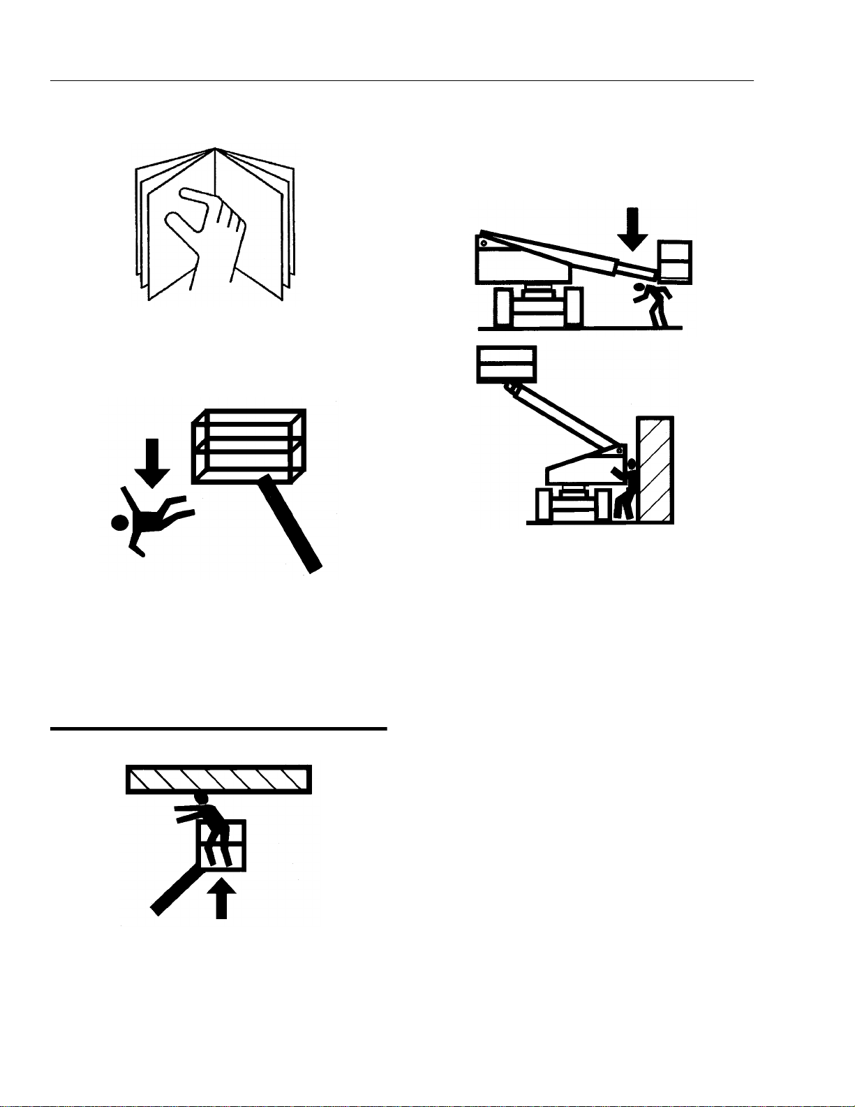
• NEVER PLACE HANDS OR ARMS IN TOWER BOOM
OR UPRIGHT MECHANISM.
• KEEP ALL NON-OPERATING PERSONNEL AT LEAST
2 METERS AWAY FROM THE MACHI NE AT ALL
TIMES.
• IF PLATFORM OR BOOM IS CAUGHT SO THAT ONE
OR MORE WHEELS ARE OFF THE FLOOR, ALL PERSONNEL MUST BE REMOVED FROM PLATFORM
BEFORE ATTEMPTING TO FREE MACHINE. USE
CRANES, FORKLIFT TRUCKS OR OTHER EQUIPMENT TO REMOVE PERSONNEL AND STABILIZE
MACHINE MOTIO N , IF NECESSARY.
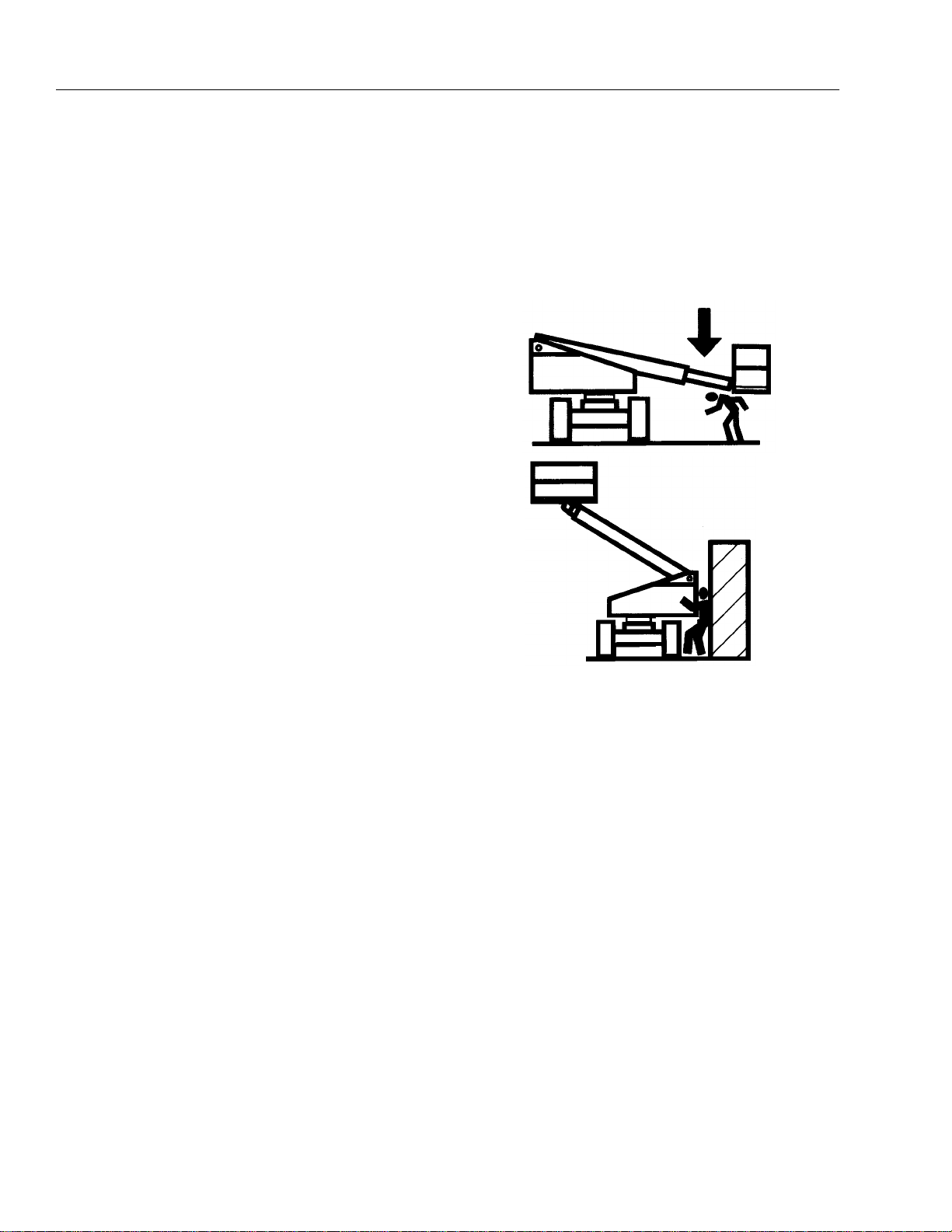
• THE OPERATOR IS RESPONSIBLE TO AVOID OPERATING MACHINE OVER GROUND PERSONNEL AND
TO WARN THEM NOT TO WORK, WALK OR STAND
UNDER A RAISED B OOM OR PL ATFORM. POSITI ON
BARRICADES ON FLOOR IF NECESSAR Y.
1-6 – JLG Lift – 3120883
Page 15
SECTION 1 - SAFETY PRECAUTIONS
.
• ENSURE MACHINE IS POSITIONED ON A FIRM,
LEVEL AND UNIFORM SUPPORTING SURFACE
BEFORE RAISING OR EXTENDING BOOM.
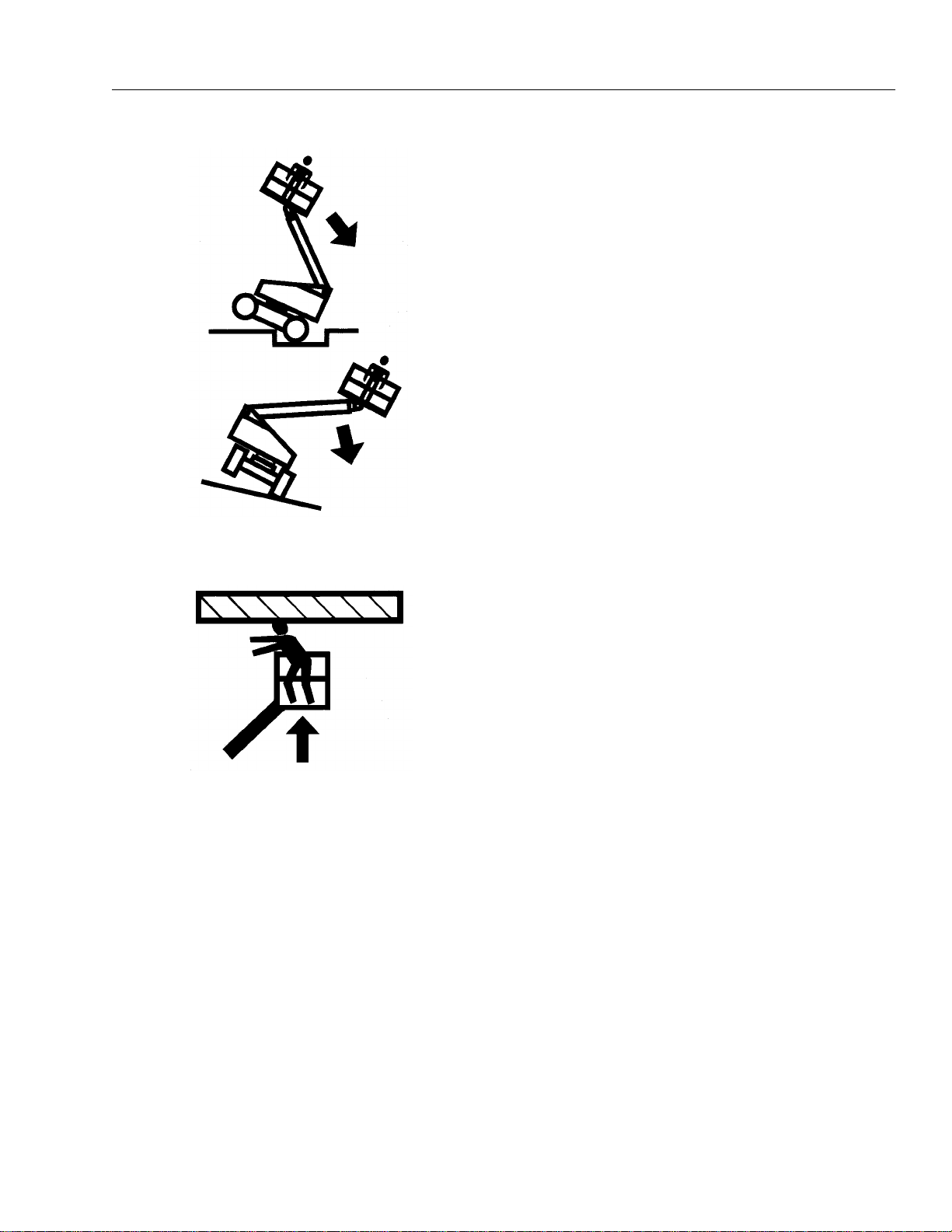
• CHECK CLEARANCES AB OVE, ON SIDES AND BOTTOM OF PLATFORM WHEN RAISING, LOWERING,
SWINGING, AND TELESCOPING BOOM.
• EXERCISE EXTREME CAUTION AT ALL TIMES TO
PREVENT OBSTACLES FROM STRIKING OR INTER-
FERING WITH OPERATING CONTROLS AND PERSONS IN PLATFORM.
• ENSURE THAT OPERATORS OF OTHER OVERHEAD
AND FLOOR MACH INES ARE AWARE OF THE AERI AL
PLATFORMS PRESENCE. DISCONNECT POWER TO
OVERHEAD CRANES. POSITION BARRICADES ON
FLOOR IF NECESSARY.
• NEVER "SLAM" A CONTROL SWITCH OR LEVER
THROUGH NEUTRAL TO THE OPPOSITE DIRECTION.
ALWAYS RETU RN SWITCH TO NEUTRA L AND STOP;
THEN MOVE SWITCH TO THE DE SIRED POSI TION.
OPERATE LEVERS WITH SLOW, EVEN PRESSURE.
• DO NOT CARRY MATERIALS ON PLATFORM RAILING
UNLESS APPROVED BY JLG INDUSTRIES INC.
• NEVER PUSH OR PULL THE MACHINE OR OTHER
OBJECTS BY TELESCOPING THE BOOM.
• NEVER USE BOOM FOR ANY PURPOSE OTHER
THAN POSITIONING PERSON NEL, THEIR TO OLS
AND EQUIPMENT.
• NEVER EXCEED MANUFACTURERS RATED PLATFORM CAPACITY - REFER TO CAPACITY DECAL ON
MACHINE. DISTRIBUTE LOADS EVENLY ON PLATFORM FLOOR.
• NEVER OPERATE A MALFUNCTIONING MACHINE. IF
A MALFUNCTION OCCURS, SHUT DOWN THE
MACHINE, RED TAG IT, AND NOTIFY PROPER
AUTHORITIES.
• DO NOT REMOVE, MODIFY, OR DISABLE FOOTSWITCH BY BLOCKING OR ANY OTHER MEANS.
• DO NOT AS SIST A STUCK OR DISABLED MACHINE
BY PUSHING OR PULLIN G EXCEPT BY PULLING AT
CHASSIS TIE-DOWN LUGS.
• NEVER ATTEMPT USING BOOM AS A CRANE.
STRUCTURAL DAMAGE OR TIPPING MAY OCCUR.
• STOW B OOM AND SHUT OFF ALL POWER BEFORE
LEAVING MACHINE.
• NO STUNT DRIVING OR HORSEPLAY IS PERMITTED.
3120883 – JLG Lift – 1-7
Page 16

SECTION 1 - SAFETY PRECAUTIONS
• NEVER ATTEMPT TO FREE A MACHINE STUCK IN
SOFT GROUND OR A S SI ST A MACH INE UP A STEE P
HILL OR RAMP BY USING BOOM "LIFT", "TELESCOPE", OR "SWING " FU N C TIONS.
• NEVER ATTACH WIRE, CABLE, OR ANY SIMILAR
ITEMS TO PLATFORM.
• DO NOT PLACE BOOM OR PLATFORM AGAINST ANY
STRUCTURE TO STEADY PLATFORM OR SUPPORT
STRUCTURES.
• DO NOT USE THE LIFT, SWING, OR TELESCOPE
FUNCTIONS FOR THE BOOM, TO MOVE EITHER THE
MACHINE OR OTHER OBJECTS.
• HYDRAULIC CYLINDERS SHOULD NEVER BE LEFT
FULLY EXTENDED OR RETRACTED FOR ANY
LENGTH OF TIME. ALWAYS "BUMP" CONTROL IN
OPPOSITE DIRECTION SLIGHTLY WHEN FUNCTION
BEING USED REACHES END OF TRAVEL. THIS
APPLIES TO MACHINES IN OPERATION OR IN
STOWED MODE.
• DO NOT OPERATE ANY MACHINE ON WHICH DANGER, WARNING, CAUTION OR INSTRUCTION PLACARDS OR DECALS ARE MISSING OR ILLEGIBLE.
• MACHINE MUST ALWAYS BE SHUT DOWN WHEN
REFUELING. NO SMOKING IS MA NDATORY. NEVER
REFUEL DURING AN ELECTRICAL STORM. ENSURE
THAT FUEL CAP IS CLOSED AND SECURE AT ALL
OTHER TIMES.
1.7 TOWING AND HAULING
• DO NOT TOW A MACHINE EXCEPT IN AN EMERGENCY. SEE SECTION 6 FOR EMERGENCY TOWING
PROCEDURES.
• LOCK TURNTABLE BEFORE TRAVELING LONG DISTANCES OR BEFORE HAULING MACHINE ON A
TRUCK OR TRAILER.
1-8 – JLG Lift – 3120883
Page 17

SECTION 2 - PREPARATION AND IN SPECTION
SECTION 2. PREPARATION AND INSPECTION
2.1 GENERAL
This section provides the necessary information needed
by those personnel that are responsible to place the
machine in operation readiness, and lists checks that are
performed prior to use of the machine. It is important that
the information contained in this section be read and
understood before any attempt is made to operate the
machine. Ensure that all the necessary inspections have
been completed successfully before placing the machine
into service. These procedures will aid in obtainin g maximum service life and safe operation.
SINCE THE MACHINE MANUFACTURER HAS NO DIRECT CONTROL OVER THE FIELD INSPECTION AND MAINTENANC E,
SAFETY IS THE RESPONSIBILITY OF THE OWNER/OPERATOR.
2.2 PREPARATION FOR USE
Before a new machine is put into operation it must be
carefully inspecte d for any e vidence of damage resulting
from shipment and inspected pe riodically thereafter, as
outlined in Delivery and Frequent Inspection. (During initial start-up and run,) the unit should be thoroughly
checked for hydraulic leaks. A check of all components
should be made to assure their security.
All preparation n ecessar y to pl ace the machin e in oper ation readiness status is the responsibility of management
personnel. Preparation requires good common sense,
(i.e. lift works smoothly and brakes operate properly) coupled with a series of visual inspections. The mandatory
requirements are given in the Daily Walk Around Inspection.
It should be assured that the items appearing in the Delivery and Frequent Inspection and Functional Check are
complied with prior to putting the machine into service.
Frequent inspection shall be performed every 3 months or
150 hours whichever come first, or more often when
required by environment, severity, and frequency of
usage.
Chassis
1. Check front tires and wheel assemblies for loose or
worn spindles, components and hardware for security, tires for wear, damage and proper inflation.
2. Check front axle for loose, missing, and worn parts,
pivot pin for security.
3. Check steering assembly for loose or bent steer cylinder rods, steer cylinder and hydraulic lines for
leaks and security, and hardware for proper installation.
4. Check rear tires and wheel assemblies for security,
tires for wear, damage and prope r inflation.
5. Check drive hubs for da ma ge an d lea ks, a nd mo tors
for damage.
6. Check oil level in drive hubs by removing the fill
plugs and check plugs on top of each drive hub. Fill
each of the cavities until oil flows from each of the
check ports. Use Mobil DTE-11. Replace all plugs.
7. Check valves and hydraulic lines for damage, leakage and security.
8. Check pump/motor and accessories for damage,
loose or missing parts, leakage and security. Check
electrical connections for corrosion and tightness
and wiring for insulation damage. Check hydraulic
filter for condition of element. Replace as required.
NOTE: JLG recommends replacing the hydraulic filter ele-
ment after the first 50 hours of operation and then
every 600 hours thereafter, unless operating conditions requ ire earlier replacement.
2.3 DELIVERY AND FREQUENT INSPECTION
NOTE: This machine requires periodic safety and mainte-
nance inspections by an authorized JLG Dealer. A
decal located on the frame provides a place to
record (stamp) inspection dates. Check decal and
notify dealer if inspection is overdue.
The following checklist provides a systematic inspection
to assist in detecting defective, damaged, or improperly
installed parts. The checklist denotes the items to be
inspected and conditions to exam ine.
9. Check hydraulic reservoir and hydraulic lines for
damage, leakage and security.
10. Check batteries for damage, loose or missing vent
caps, electrical connections for tightness and evidence of corrosion, and electrolyte level. Add only
clean distilled water to battery after it has been
charged.
11. If equipped with on-board generator, check engine
and accessorie s for damage, loose or missing pa rt s ,
leakage and security. Check throttle solenoid and
linkage for damage, electrical connections for tightness, and evidence of corrosion and wiring for insu-
3120883 – JLG Lift – 2-1
Page 18

SECTION 2 - PREPARAT ION AND INSPECTION
lation damage. Check exhaust for damage, wear
and leakage.
Turntable
1. Check turnt abl e for dama ge , loo se or mi ssi ng p arts,
and security. Check lift cylinders and hydraulic lines
for damage, leakage and security. Check swing
drive motor for damage, loose or missing parts,
hydraulic lines and component housings for evidence of leakage; worm gear for proper mesh with
swing gear.
2. Check swing bearing for damage, wear, lubrication
and loose or missing bearing bolts.
3. Check valves and hydraulic lines for damage, leakage, security and electrical connections for tightness
and evidence of corrosion.
4. Check ground controls for damage, loose or missing parts, security, electrical connections for tightness and evidence of corrosion and wiring for
insulation damage. Assure that all switches function
properly.
5. Check all cowl and access doors for damage,
proper operation and security.
6. Check Lower Boom pivot bushings for lubrication
and wear.
7. Check Lower Boom Lift Cylinder and hydraulic lines
for damage, leakage and security.
8. Check all pin and shaft retaining hardware for security and wear.
9. Check all electrical cables for damage, loose and
corroded connections.
Boom
1. Check Lower Boom and leveling link for damage,
missing parts and security.
2. Check all pin and shaft retaining hardware for security and wear.
8. Check Mid Boom pivot shaft and lift cylinder for
damage, missing parts and security.
9. Check all pin and shaft retaining hardware for security and wear.
10. Check Upper Upright, cross pins and hydraulic lines
for damage, wear, lubrication, leakage and security.
11. Check Upper Upright for damage, wear, lubrication
and security.
12. Check hydraulic lines mounted on upright for damage, leakage and security.
13. Check Upper Boom Lift Cylinder and cross pins and
hydraulic lines for damage, wear, lubrication, leakage and security.
14. Check Upper Boom pivot pin for damage, wear,
lubrication and security.
15. Check Upper Boom for damage, missing parts and
security.
16. Check Upper Boom wear pads for damage, missing
parts and security.
17. Check Upper Boom telescope cylinder, cross pins
and hydraulic lines for damage, wear, lubrication,
leakage and security.
18. Check Platform Leveling Cylinder, cross pins and
hydraulic lines for damage, wear, lubrication, leak-
age and security.
Platform
1. Check platform and control console for damage,
loose or missing part s , and security.
2. Check control switches and levers for damage,
loose or missing parts and security. Assure that lever
and lever lock functions properly.
3. Check control switches, levers and electrical connections for tightness and evidence of corrosion,
and wiring for defects and chafing damage. Assure
that switches function properly.
3. Check hydraulic lines and electrical cable for damage, missing parts and security.
4. Check limit sw itch connecti ons and plunger fo r corrosion and security.
5. Check Lower Upright cross pins and hydraulic lines
for damage, wear, lubrication, leakage and security.
6. Check Lower Upright for damage, wear, lubrication
and security.
7. Check hydraulic lines mounted on upright for damage, leakage and security.
2-2 – JLG Lift – 3120883
Page 19

SECTION 2 - PREPARATION AND IN SPECTION
Figure 2-1. Basic Nomenclat ure
4. Check footswitch for damage, loose or missing parts
and security. Assure that footswitch functions properly and that wiring has no defects or chafing.
5. Check Platform Rotator mechanism for proper operation, damage, and security.
NOTE: Check all DANGER, WARNING, CAUTION, and
INSTRUCTION placards for legibility and security on
the entire machine.
TO AVOID INJURY, DO NOT OPERATE MACHINE IF ALL PLACARDS ARE NOT ON MACHINE OR ARE DEFACED AND NOT
READABLE. USE OF MACHINE WITHOUT CORRECT PLACARDS
IS A SAFETY VIOLATION.
3120883 – JLG Lift – 2-3
Page 20

SECTION 2 - PREPARAT ION AND INSPECTION
2.4 DAILY WALK-AROUND INSPECTION
It is the operators responsibility to inspect the machine
before the start of each workday. It is recommended that
each operator inspect the machine before operation, even
if the machine has already been put into service under
another operator. This Daily Walk-Around Inspection is the
preferred method of inspection. (Figure 2- 3)
In addition to the Daily-Walk Around Inspection be sure to
include the f o l lowing as par t of the daily inspection :
1. Overall Cleanliness.
TO AVOID INJURY DO NOT OPERATE A MACHINE UNTIL ALL
MALFUNCTIONS HAVE BEEN CORRECTED. USE OF A MALFUNCTIONING MACHINE IS A SAFETY VIOLATION.
NOTE: Check boom limit switches on upright for proper
operation and security, both visually and manually.
Lower switch cuts out drive speed when Lower
Boom is above horizontal. Upper switch cuts out
drive speed when Upper Boom is above horizontal.
Only creep drive speed will continue to function.
Check all standing surfaces for hydraulic oil spillage
and foreign objects. Ensure overall cleanliness.
2. Placards.
Keep all information and operating placards clean
and unobstructed. Cover when spray painting or
shot blasting to protect legibility.
3. Operators and Safety Manual.
Ensure that a copy of this manual is enclosed in the
manual storage holder.
4. Machine Log.
Ensure a machine operating record or log is kept,
check to see that it is current and that no entries
have been left uncleared, leaving machine in an
unsafe condition for operation.
5. Start each day with fully charged batteries.
6. Check platform footswitch for proper operation.
Switch must be depressed to operate machine.
7. Check that drive brakes hold when machine is
driven up a grade and stopped.
NOTE: On new machines, those recently overhauled, or
after changing hydraulic oil, operate all systems a
minimum of two complete cycles and recheck oil
level in reservoir.
8. Assure that all items requiring lubrication are serviced. Refer to Lubrication Chart, Figure 2-4, for specific requirements.
2.5 DAILY FUNCTIONAL CHECK
A functional check of all systems should be performed,
once the walk-around inspection is complete, in an area
free of overhead and ground level obstructions. First,
using the ground control s, check all funct ions control led
by the ground controls. Next, using the platform controls,
check all functions controlled by the platform controls.
TO AVOID SERIOUS INJURY, DO NOT OPERATE MACHINE IF ANY
CONTROL LEVERS OR TOGGLE SWITCHES CONTROLLING
PLATFORM MOVEMENTS DO N OT RETURN TO THE OFF POS ITION WHEN RELEASED.
TO AVOID A COLLISION AND INJURY IF PLATFORM DOES NOT
STOP WHEN A CONTROL SWITCH OR LEVER IS RELEASED,
REMOVE FOOT FROM FOOTSWITCH OR USE EMERGENCY STOP
TO STOP MACHINE.
1. Check boom limit switches. Raise and lower the
Lower Boom. Check for smooth operation. Check
Boom Upright tilting. (See Section 4).
NOTE: Perfor m checks from ground controls first, then from
platform controls.
2-4 – JLG Lift – 3120883
Page 21

2. Raise, extend, retract, and lower the Upper Boom.
Check for smooth operation.
3. If tower boom does not rest on stop with machine in
the stowed position, this indicates upright is out of
plumb.
4. Telescope boom IN and OUT several cycles at various degrees of elevation lengths. Check for smooth
telescope operation.
5. Swing turntable to LEFT and RIGHT a minimum of
45 degrees. Check for smooth motion.
6. Check the chassis out of level indicator located on
the platform control console by driving, with the
machine in level position, up a suitable ramp of at
least 4° slope. Check the out of level alarm, with the
machine on the ramp, raise the upper boom until it
is parallel with the chassis. DO NOT RAISE ABOVE
THE PARALLEL POSITION. If the light does not illuminate, return the machine to a level surface, shut
down the machine, and contact a qualified technician before resuming operation.
DO NOT DRIVE ON GRADES WHICH EXCEED THE RAT ED
GRADEABILITY OF THE MACHINE AS INDICATED ON THE
SERIAL NUMBER PLATE. DO NOT DR IVE ON SIDESLOPES
WHICH EXCEED 3 DEGREES.
7. Check that platform self-leveling system functions
properly during raising and lowering of boom.
8. Check rotator for smooth operation and assure platform will rotate 75 degrees in both directions from
centerline of boom.
9. Drive forward and reverse; check for proper operation.
SECTION 2 - PREPARATION AND IN SPECTION
FOOTSWITCH MUST BE DEPRESSED PRIOR TO ACTIVATING ANY
FUNCTION CONTROL, OTHERWISE THE FUNCTION WILL NOT
WORK.
With footswitch depressed, operate LIFT and hold
control. Remove foot from footswitch, motion should
stop. If it does not, shut down machine and contact
a qualified service technician.
12. Place the GROUND/PLATFORM SELECT switch to
GROUND. Platform controls should not operate.
13. Place GROUND/PLATFORM SELECT switch to OFF.
Platform/Ground controls should not operate.
2.6 TORQUE REQUIREMENTS
The Torque Chart ( Fig ur e 2 -5 ) co nsi st s o f s tan d ard tor qu e
values based on bolt diameter and grade, also specifying
dry, wet and loctite torque values in accordance with recommended shop practices. This chart is provided as an
aid to the operator in the event he/she notices a condition
that requires prompt at tention during t he walk-around
inspection or during operation, until the proper service
personnel can be notified. The Service and Mainte nance
section provides specifi c to rque valu es and period ic ma intenance procedures with a listing of individual components. Utilizing this torque chart in conjunction with
preventive maintenance section will enhance safety, reliability, and performance of the machine.
10. Steer left and right; check for proper operation.
11. Footswitch.
FOOTSWITCH MUST BE ADJUSTED SO THAT FUNCTIONS WILL
OPERATE WHEN PEDAL IS APPROXIMATELY AT ITS CENTER OF
TRAVEL. IF SWITCH OPERATES WITHIN LAST 1/4" (6 MM) OF
TRAVEL, TOP OR BOTTOM, IT SHOULD BE ADJUSTED.
Updated 5-21-99
3120883 – JLG Lift – 2-5
Page 22

SECTION 2 - PREPARAT ION AND INSPECTION
Figure 2-2. Daily Walk-Around Inspecti on (Sheet 1 of 3)
2-6 – JLG Lift – 3120883
Page 23

SECTION 2 - PREPARATION AND IN SPECTION
GENERAL
Begin your Walk-Around Inspection at item 1, as noted on
the diagram. Continue to your right (counterclockwise
viewed from the top) checking each item in sequence for
the conditio ns l isted in the fol lowing checklist.
TO AVOID INJURY DO NOT OPERATE MACHINE UNTIL ALL MALFUNCTIONS HAVE BEEN CORRECTED. USE OF A MALFUNCTIONING MACHINE IS A SAFETY VIOLATION.
TO AVOID POSSIBLE INJURY BE SURE MACHINE POWER IS OFF
DURING “WALK-AROUND INSPECTION”.
NOTE: Do not overlook visual inspection of chassis under-
side. Checking thi s area may result in discover y of
conditions which could cause extensive machine
damage.
1. Platform Assembly - No loose or missi ng parts; no
visible damage. Platform mounting pins secure.
Footswitch in good working order; not modified,
disabled or blocked.
2. Platform Control Console - Switches and control
lever properly secured; no loose or missing parts;
no visible damage; placards secure and legible;
control lever and switches return to neutral; control
lever lock functions properly; emergency stop
switch functions properly; control markings legible.
3. Fly Boom Nose and Platform Support - Ensure fly
boom nose and platform support are free of debris,
obstructions, et c.
4. Rotator Cylinder - No visible damage; motor and
cylinder pins secure; hydraulic hoses undamaged,
not leaking.
5. Slave Cylinder - No visible damage; pivot pins
secure; hydraulic hose s undamaged, not leaking.
6. Boom Sections/Lift Cylinders and Master Cylinder No visible damage; pivot pins secure; hydraulic
hoses undamaged, not leaking.
7. Telescope Cylinder and Power Track - No visible
damage; no loose or missing hardware.
8. Limit Switches - Swit ches o perable; no visi ble da mage.
10. Drive Wheel/Tire Assembly, Right Rear - Properly
secured; no loose or missing wheel bolts; no visible
damage.
11. Hydraulic Oil Filter Housing - Secure; no visible
signs of damage or l e akage.
12. Hydraulic Pump and Reservoir - Properly secured;
no visible damage or hydraulic leaks. Recommended hydraulic fluid level on dipstick (system
shut down, boom in stowed position). Breather cap/
dipstick secure and working.
13. Turntable Bearing - No loose or missing hardwa re;
no visible damage; evidence of proper lubrication.
No loose bolts or looseness between bearing and
structure.
14. Fuel Supply - Fuel filler cap secure; Tank - no visible
damage, decals secure and legible.
15. Battery Compartment Right Side - Batteries have
proper electrolyte level; cables tight; no visible damage or corrosion.
16. Cowling and Latches - All cowling, doors and
latches in working condition; properly secured; no
loose or missing parts.
17. Battery Charger - No damage; properly secured.
18. Valve - No loose or missing parts; evidence of leakage, unsupported wires or hoses; damaged or broken wires.
19. Boom/Upright - No visible damage; All pins properly secured. Upright in vertical position. If Upright
does not rest on stop with machine in the stowed
position, this indicates upright is out of plumb.
20. Steer Wheel/Tire Assembly, Right Front - Properly
secured; no loose or missing wheel bolts; no visible
damage.
21. Counterweight - No loose or missing hardware;
properly secured.
22. Steer Cylinder - Properly secured; no visible damage or signs of leakage; evidence of proper lubrication.
23. Engine Oil Supply - Full mark on dipstick; filler cap
and filter secure.
9. Drive Axle and Motor - No loose or missing hardware; No visible damage; no evidence of leakage.
Figure 2-2., Daily Walk -Aro und Inspectio n
(Sheet 2 of 3)
3120883 – JLG Lift – 2-7
Page 24

SECTION 2 - PREPARAT ION AND INSPECTION
24. Tie Rod Ends and Steering Spindles - No loose or
missing parts; no v isi ble damage. Tie rod end st ubs
locked.
25. Drive Wheel/Tire Assembly, Left Rear - Properly
secured; no loose or missing wheel bolts; no visible
damage.
26. Ground Controls - Switches operable; no visible
damage; emergency stop switch functions properly; placards secure and legible.
27. Manual Descent Valve - No visible damage; no evidence of leakage.
28. Cowling and Latches - All cowling, doors and
latches in working condition; properly secured; no
loose or missing parts.
29. Battery Compartment - Batteries have proper electrolyte level; cables tight; no visible damage or corrosion.
30. Control Valve - No loose or missing parts; evidence
of leakage; unsupported wires or hoses; damaged
or broken wires.
Figure 2-2., Daily Walk- Around Inspection
31. Swing Motor and Worm Gear - No loose or missing
hardware; no visible damage; evidence of proper
lubrication.
32. Drive Wheel/Tire Assembly, Left Rear - Properly
secured; no loose or missing wheel bolts; no visible
damage.
33. Frame - No visible damage; no loose or missing
hardware (top and underside).
34. Cowling and Latches - All cowling, doors and
latches in w orking condition; properly secured ; no
loose or missing parts.
35. Platform Pivot Pins - Properly secured.
36. Plat form Gat e - Latc h and Hinge s in wor king c ondition; properly secured; no loose or missing parts.
(Sheet 3 of 3)
2.7 BATTERY MAINTENANCE AND
CHARGING
Battery Maintenance, Qu arterly
1. Open battery compartment cover to allow access to
battery terminals and vent caps.
WHEN ADDING WATER TO BATTERIES, ADD WATER UNTIL ELECTROLYTE COVERS PLATES. DO NOT CHARGE BATTERIES
UNLESS ELECTROLYTE COVERS THE PLATES.
NOTE: When adding disti lled w ater to batteries , no n-metalli c
containers and/or funnels must be used.
To avoid electrolyte overflow, add distilled water to
batteries after charging.
When adding water to the battery, fill only to level
indicated or 3/8" above separators.
2. Remove all vent caps and inspect electrolyte level of
each cell. Electrolyte level should be to the ring
approximately one inch from top of battery. Fill bat-
teries with distilled water only. Replace and secure
all vent caps.
3. Remove battery cables from each battery post one
at a time, negative first. Clean cables with acid neutralizing solution (e.g. baking soda and water or
ammonia) and wire brush. Replace cables and/or
cable clamp bolts as re quired.
4. Clean battery post with wire brush then re-connect
cable to post. Coat non-contact surfaces with mineral grease or petroleum jelly.
5. When all cables and terminal posts have been
cleaned, ensure all cables are properly positioned
and do not get pinched. Close battery compartment
cover.
6. Start hydraulic system and ensure that it functions
properly.
2-8 – JLG Lift – 3120883
Page 25

SECTION 2 - PREPARATION AND IN SPECTION
Optional On Board Generator
EXHAUST GAS HAZARD. RUN THE GENERATOR IN A WELL VENTILATED AREA ONLY.
WHEN THE GENERATOR ENABL E CONTROL LOCATED IN TH E
PLATFORM CONTROL BOX IS IN THE ON POSITION AND THE
GROUND EMERGENCY STOP SWITCH IN ON (PULLED OUT), THE
GENERATOR WILL START AUTOMATICALLY WHEN THE BATTERIES REACH A L OW-CHARGE STATE A UTOMATICALLY
CHARGING THE BATTERIES.
NOTE: The engine will automatically shut down under the
following conditions:
High Engine Oil Temperature
Low Engine Oil Pressure
Engine Overspeed
Generator Overvoltage
TO AVOID INJURY FROM AN EXPLOSION, DO NOT SMOKE OR
ALLOW SPARKS OR A FLAME NEAR BAT TERY DURING SERVICING. ALWAYS WEAR EYE AND HAND PROTECTION WHEN SERVICING BATTERIES.
Battery Charging (On Board Charger)
1. For maximum battery life:
a. Avoid completely discharging the batteries.
b. Fully charge the batteries each day the machine
is used.
c. Charge the batteries at available times between
full charges.
d. Be sure the battery fluid covers the battery
plates before charging, but to avoid overflow, do
not top off the fluid level until charging.
2. To charge the batteries, connect the charger to a
115 or 220 volt source with a 20 amp minimum
capacity.
3. The charge cycle is complete when the ammeter
reads 0 amps. Any reading indicates the charge
cycle is not complete.
4. The Charger will shut off automatically when the bat-
teries are fully charged.
5. Depleted batteries will take approximately 17 hours
to charge.
Updated 11-3-99
3120883 – JLG Lift – 2-9
Page 26

SECTION 2 - PREPARAT ION AND INSPECTION
Figure 2-3. Lubrication Chart
Updated 6-1-99
2-10 – JLG Lift – 3120883
Page 27

SECTION 2 - PREPARATION AND IN SPECTION
Table 2-1. Lubrication Chart
Components
Lubrication
Swing Bearing - Internal
1
Ball Bearing
Swing Bearing - Teeth
2a
End Bearings - Worm
2b
Gear*
Hydraulic Fluid (Oil)
3
Hydraulic Filter
4
Wheel Dri ve Hub
5
Wheel Bearing
6
Spindles/Bushing
7
Boom Pivot Pins/
8
Bushing
Engine
9
Number/Type
Lube Points
2 Grease Fittings A/R MPG X
Spray On A/R OGL X More frequent lubr ication interv als may be
2 Grease Fittings A/R MPG X Remove grease fitt ings and install pl ugs after
Fill Cap 15.1 liters (t ank) HO X Check oil every 10 hours of operati on.
N/A N/A N/A X Replace filte r element afte r first 50 hour s and
Fill Plug/Half F ull 0.5 liters (1/2 F ull) EPG L X Check oil level at s ide plug on hub d aily .
Repack A/R MPG X
N/A A/R LL At Spindle/Bushi ng Replacement Coat I.D. of bushi ngs prior to in stalling king
N/A A/R LL At boom pivot pi ns/bushing re placement Coat I.D. of bushing s prior to inst alling pins.
Fill Cap Refer to Engine
Capacity Lube
Manual
EO Check daily. Change in accordance with
Interval Hours
3 Months
150 hrs
6 Months
300 hrs
1 Year
600 hrs
2 Years
1200 hrs
Comments
required.
greasing.
Change oil every 1200 hours of operation.
every 300 hours the reafter .**
Change after firs t 150 hours th en every 1200
hours of operati on.
pins.
engine manual.
NOTES: KEY TO LUBR ICANTS
Lubrication intervals are bas ed on machine operation under norm al conditions. For machines used in multi shift operations and/ or exposed to hostile environments or conditions, lubri cation frequencies must be increased accordingly .
* If necessary in stall grease f ittings into worm gear housin g and grease bearings.
DO NOT OVERGREASE BEARINGS. OVERGREASING BEARINGS WILL RESULT IN
BLOWING OUTER SEA L IN HO US ING .
** Under certain conditions, it may be necessary to replace the hydraul ic filter on a more frequent basis. A common symptom of a dirty filter is sluggishness
experienced in h ydraulic functions .
EO
EPGL
HO
MPG
LL
OGL
Engine Oil
Extreme Pressure Ge ar Lube
Hydraulic Fluid (Mobil DTE-1 1M)
Multi-Purpose Grease
Synthetic Lithium Lubr icant
Open Gear Lubric ant - Mobiltac 3 75 or
equivalent
Updated 11-3-99
3120883 – JLG Lift – 2-11
Page 28

SECTION 2 - PREPARAT ION AND INSPECTION
18
19
34
37
61
68
UNPLATED
CAP SCREWS
WITH LOC-WEL PATCH
UNBRAKO 1960 SERIES
SOCKET HEAD CAP SCREW
TORQUE
NM
TORQUE
(as received)
(KG)
CLAMP LOAD
)
NM
(LOCTITE
242 OR 271
262)
NM
(LOCTITE
NM
(LUB.)
1442
1651
2377
18
21
41
30
2
4
4
5
1
1
2
6
12
14
25
2631
3493
68
41
34
54
27
48
95
3983
4822
75
109
61
85
48
75
102
5384
122
95
81
149
156
6437
7253
183
163
130
146
122
109
210
224
8256
9208
224
258
188
209
149
176
285
298
10251
11612
326
359
244
277
231
244
495
542
15150
16919
570
631
408
456
380
434
793
861
20956
23088
895
983
658
724
624
678
1173
1241
27488
30074
1492
1342
931
1079
922
1003
1681
1871
34610
38828
1898
2136
1396
1566
1464
1302
2373
2549
43954
48671
2712
2983
1970
2183
1844
2034
3145
3308
52391
59648
3559
4068
2586
2935
2413
2766
4122
4433
63731
71669
4712
5322
3430
3856
3200
3607
SAE GRADE 8
SAE GRADE 5
VALUES FOR ZINC PLATED BOLTS ONLY
(DRY OR
SAE GRADE 8 BOLTS & GRADE 8 NUTS
CLAMP
(LOCTITE
(LOCTITE
TORQUE
(DRY OR
SAE GRADE 5 BOLTS & GRADE 2 NUTS
CLAMP
AREA
STRESS
THREAD
DIA.
BOLT
NM
LOC. 263)
(KG)
LOAD
)
NM
242 OR 271
262)
NM
NM
(LUB.)
NM
LOC. 263)
(KG)
LOAD
(SQ. CM)
(CM)
2
2
245
272
1
1
1
1
172
191
0.0153
0.0168
0.2845
3
3
372
417
2
2
2
2
263
277
0.0232
0.0258
0.3505
5
5
572
599
3
3
4
4
408
426
0.0356
0.0374
0.4166
7
8
717
817
4
4
6
5
508
583
0.0445
0.0508
0.4826
16
19
1297
1488
16
12
9
10
11
14
916
1052
0.0808
0.0925
0.6350
34
34
2141
2821
29
26
22
23
19
18
26
23
1515
1678
0.1473
0.1331
0.7938
61
68
3175
3583
54
48
38
43
34
31
48
41
2241
2540
0.2230
0.1969
0.9525
95
109
4332
4854
81
75
68
61
68
48
68
75
3085
3425
0.3015
0.2700
1.1112
149
163
5783
6532
115
136
92
108
75
88
102
122
4105
4854
0.4061
0.3604
1.2700
204
231
7539
8278
163
183
133
148
109
122
149
163
5874
5262
0.5156
0.4623
1.4288
298
326
9231
10433
224
258
183
207
149
176
204
231
7394
6532
0.6502
0.5740
1.5875
515
570
15241
13653
387
448
325
363
271
298
353
407
9662
10796
0.9474
0.8484
1.9050
814
895
18870
20775
644
705
523
576
434
475
583
637
14697
13336
1.2929
1.1735
2.2225
1220
1356
23360
27080
915
997
785
858
651
719
868
949
19142
17509
1.6840
1.5392
2.5400
1736
1953
31162
34927
968
1087
814 1139
895 1254
1085
1193
21546
19187
2.1742
1.9380
2.8575
2468
2712
38554
43818
1593
1762
1368
1516
1139
1247
1519
1681
27035
24404
2.7254
2.4613
3.1750
3227
3688
47174
53570
2068
2373
1792
2042
1492
1708
1980
2278
29076
33113
2.9337
3.3401
3.4925
4284
4827
57380
142200
2746
3118
2379
2676
1980
2630
35381
3.5687
4.0132 39781 2983 2224
3.8100
Figure 2-4. Torque Chart
9
8
7
7
6
THD
SIZE
40
48
40
36
32
28
18
16
14
13
12
11
32
32
24
20
24
24
20
20
8
6
4
10
1/4
5/16
3/8
7/16
1/2
9/16
18
5/8
18
10
3/4
16
7/8
14
12
12
1
1-1/8
1-1/4
12
12
1-1/2
6
1-1/2
12
Note: These torque values do not apply to cadium plated fasteners.
2-12 – JLG Lift – 3120883
Page 29

SECTION 3 - USER RESPONSIBILITIES AND MACHINE CONTROL
SECTION 3. USER RESPONSIBILITIES AND MACHINE CONTROL
3.1 GENERAL
SINCE THE MANUFACTURER HAS NO DIRECT CONTROL OVER
MACHINE APPLICATION AND OPERATION, CONFORMANCE WITH
GOOD SAFETY PRACTICES IN THESE AREAS IS THE RESPONSIBILITY OF THE USER AND HIS/HER OPERATING PERSONNEL.
This section provides the necessary information needed
to understand control functions. Included in this section
are the operating characteris tic s and limitations, and functions and purposes of controls and indicators. It is important that the user read and understand the proper
procedures before operating the machine. These procedures will aid in obtaining op timum lift service and s afe
operation.
3.2 PERSONNEL TRAINING
The aerial platform is a personnel handling device; therefore, it is essential that it be operated and maintained only
by authorized and qua lified personnel w ho have demonstrated that they understand the proper use and maintenance of the machine. It is important that all personnel
who are assigned to and are responsible for the operation
and maintenance of the machine undergo a thorough
training program a nd check out perio d i n order t o bec ome
familiar with the characteristics prior to operating the
machine.
Persons under the influence of drugs or alcohol or who
are subject to seizures, dizziness or loss of physical control must not be permitted to operate the machine.
Operator Training.
Operator training must include instruction in the following
areas:
1. Use and limitations of the platform controls, ground
controls, emergency controls and safety systems.
2. Knowledge and understanding of this manual and of
the control markings, instructions and warnings on
the machine itself.
3. Knowledge and understanding of all safety work
rules of the employer and of Federal, State and local
statutes, including training in the recognition and
avoidance of potential hazards in the work place;
with particular attention to the work to be performed.
4. Proper use of all required personnel safety equipment, in particular th e wea ring of a safety harness or
other approved fall protection devices with a lanyard
attached to a designated attach point, on the platform, at all times.
5. Sufficient knowledge of the mechanical operation of
the machine to recognize a malfunction or potential
malfunction.
6. The safest means to operate the machine where
overhead obstructions, other moving equipment,
and obstacles, depressions, holes, dropoffs, etc. on
the supporting surface exist.
7. Means to av oid the hazards o f unprotected el e ctrical
conductors.
8. Any other requirements of a specific job or machine
application.
Training Supervision.
Training must be done under the supe rvis ion of a qualified
person in an open area free of obstru ctions until the
trainee has developed the ability to safely control a
machine in congested work locations.
Operator Responsibility.
The operator must be in structed that he/she has t he
responsibility and authori ty to shut down the machine in
case of a malfunction or other unsafe condition of either
the machine or the job site and to request further information from his/her supervisor or an authorized JLG Distributor before proceeding.
NOTE: Manufacturer or Di st r i but or w il l pr ovi de qu al i fie d pe r -
sons for train ing assistan ce with first unit (s) deli vere d
and thereafter as requested by the user or his/her
personnel .
3120883 – JLG Lift – 3-1
Page 30

SECTION 3 - USER RESPONSIBILITIES AND MACHINE CONTRO L
3.3 OPERATING CHARACTERISTICS AND
LIMITATIONS
General
A thorough knowledge of the operating characteristics
and limitations of the machine is always the first requirement for any user, regardless of the users experience with
similar types of equipment.
Placards
Important points to remember during operation are provided at the control stations by DANGER, WARNING,
CAUTION, IMPORTANT and INSTRUCTION placards. This
information is placed at various locations for the express
purpose of alerting personnel of potential hazards constituted by the operating characteristics and load limitations
of the machine. See FOREWORD for definitions of the
above placards.
TO AVOID FORWARD OR BACKWARD UPSET, DO NOT O VERLOAD MACHINE, OPERATE ON OUT-OF-LEVEL SURFACE OR
OPERATE WITH THE BOOM UPRIGHT TILTING. (SEE FIGURE 4-2.
UPRIGHT POSITIONING).
3.4 CONTROLS AND INDICATORS
These machines are equipped with control panels that
use symbols and words to in dicate control function s. On
some machines, the contro l panels may use symbols
only. Refer to Table 3-1 for these symbols and their corresponding functions.
Ground Control Station
DO NOT OPERATE FROM GROUND CONTROL STATION WITH
PERSONNEL IN THE PLATFORM EXCEPT IN AN EMERGENCY.
Capacities
Raising boom above horizontal with or without any load in
platform, is based on the following criteria:
1. Machine is positioned on a smooth, firm and level
surface.
2. Load is within manufacturers rated design capacity.
3. All machine systems are functioning properly.
4. Proper tire pressure.
5. Machine is as originally equipped from JLG.
Stability
This machine as originally manufacture d by JLG Industries, Inc., when operated within its rated capacity on a
smooth, firm and level supporting surface and in accordance with the instructions provided on the machine and
in this manual, provides a stable machine for all positions.
Machine stability is based on two (2) conditions which are
called FORWARD stability and BACKWARD stability. The
machine’s position of least FORWARD stability is shown in
Figure 3-1 and its position of least BACKWARD stability is
shown in Figure 3-2.
PERFORM AS MANY PRE-OPERATIONAL CHECK AND INSPECTIONS FROM GROUND CONTROLS AS POSSIBLE.
NOTE: When machine is shut down the Platform/Ground
Select switch and Emergency Stop must be positioned to OFF.
1. Power/Emergency Stop Switch.
A two-position red mushroom shaped switch fur-
nishes power to PLATFORM/GROUND SELECT
switch when pulled out (on). When pushed in (off),
power is shut off to the PLATFORM/GROUND
SELECT switch.
2. Platform/Ground Select Switch.
A three position, key operated switch supplies
power to the platform control console when positioned to PLATFORM. With the switch key held in the
GROUND position, power is shut off to platform and
only ground controls are operable. When released
from GROUND position the switch spring returns to
the (off) position.
NOTE: With PLATFORM/GROUND SELECT switch in the
center position, power is shut off to controls at both
operating stations.
3-2 – JLG Lift – 3120883
Page 31

SECTION 3 - USER RESPONSIBILITIES AND MACHINE CONTROL
Figure 3-1. Position of Least Forward Stability
3120883 – JLG Lift – 3-3
Page 32

SECTION 3 - USER RESPONSIBILITIES AND MACHINE CONTRO L
Figure 3-2. Position of Least Backward Stability
3-4 – JLG Lift – 3120883
Page 33

SECTION 3 - USER RESPONSIBILITIES AND MACHINE CONTROL
Figure 3-3. Ground Control Station
Updated 8-18-99
3120883 – JLG Lift – 3-5
Page 34

SECTION 3 - USER RESPONSIBILITIES AND MACHINE CONTRO L
3. Rotate.
A three position ROTATE control switch permits rota-
tion of the platform when positioned to left or right.
4. Platform Leveling Override.
A three position LEVEL control switch allows the
operator to compensate for any difference in the
automatic self leveling system by positioning the
control switch to UP or DOWN.
5. Articulating Jib Boom (If equipped)
The Articulating Jib Boom control switch provides
raising and loweri ng of the jib when positioned up or
down.
6. Lower Boom Lift.
Provides for raising and lowering of Lower Boom
when positioned to UP or DOWN.
7. Upper Boom Lift.
Provides for raising and lowering of Upper Boom
when positioned to UP or DOWN.
8. Telescope.
Provides for extension and retraction of Upper Boom
when positioned to IN or OUT.
9. Swing.
The SWING control switch provides 360 degrees
non-continuous turntable rotation. To activate
SWING, position switch to LEFT or RIGHT.
10. Circuit Breakers.
The circuit breakers open (pop out) to indicate a
short or overload somewhere on the machine.
NOTE: The engine will automatically shut down under the
following conditions:
High Oil Temperature
Low Oil Pressure
Engine Overspeed
Overvoltage
NOTE: The engine will not start if the batteries are fully
charged or if the Generator Enable switch on the
platform console is not in the on position.
13. Generator/Engine Start Button.
The generator/engine start push-button switch
allows the generator to be started manually to topoff the battery charge. The generator will start automatically when the batteries reach a low-charge
state and the Generator Enable switch on the platform console is in the on position.
Platform Control Station
1. Footswitch.
The footswitch is a safety feature. To operate any
function, the footswitch must be depressed and the
function se lect ed wit hin sev en seco nds. The en able
light in the light panel indicates that the controls are
enabled; as long as functions continue to be used
the controls remain enabled. If a function is not
selected within seven seconds, or if a seven second
lapse between ending one function and beginning
the next function, the enable light will go out and the
footswitch must be recycled to re-enable the controls.
Releasing the footswitch removes power from all
controls and applies the drive brakes.
11. Battery Indicator and Hourmeter.
An hourmeter, installed in the upper porti on of the
Ground Control Box, registers the amount of
machine operating time. The hourmeter registers up
to 9,999.9 hours and cannot be reset.
12. System Distress Indicator .
The system distress indicator lights to signify an
abnormal condition for the generator engine (high
oil temperature or low oil pressure) or, on all electric
machines, an electrical system fault.
Updated 8-18-99
TO AVOID SERIOUS INJURY, DO NOT REM OVE, MODIFY OR DISABLE THE FOOTSWITCH BY BLOCKING OR ANY OTHER MEANS.
FOOTSWITCH MUST BE DEPRESSED PRIOR TO ACTIVATING ANY
FUNCTION CONTROL, OTHERWISE THE FUNCTION WILL NOT
OPERATE.
FOOTSWITCH MUST BE ADJUSTED SO THAT FUNCTIONS WILL
OPERATE WHEN PEDAL IS APPROXIMATELY AT ITS CENTER OF
TRAVEL. IF SWITCH OPERATES WITHIN LAST 1/4" OF TRAVEL,
TOP OR BOTTOM, IT SHOULD BE ADJUSTED.
3-6 – JLG Lift – 3120883
Page 35

SECTION 3 - USER RESPONSIBILITIES AND MACHINE CONTROL
Figure 3-4. Platform Console
2. Power/Emergency Stop.
A two-position red mushroom shaped switch fur-
nishes power to PLATFORM Controls when pulled
out (on). When pushed in (off), power is sh ut off to
the platform functions.
Within about 2 seconds of pulling the switch out, the
machine will perform a d iagnostic check of the various electrical circuits, and if everything is OK, the
platform alarm will beep once. During this time the
lights on the indicator panel will also blink once as a
bulb check.
3. Lower Boom Lift.
Provides for raising and lowering of Lower and Mid
Boom when positioned to UP or DOWN. Upper lift
will not function when operating lower lift.
NOTE: Main Lift, Swing, and Drive control levers are spring-
loaded and will automatically return to neutral (off)
position w hen released.
TO AVOID SERIOUS INJURY, DO NOT OPERATE MACHINE IF ANY
CONTROL LEVERS OR TOGGLE SWITCHES CONTROLLING
PLATFORM MOVEMENT DO NOT RETURN TO T HE OFF OR NEUTRAL POSITION WHEN RELEASED.
Updated 8-18-99
3120883 – JLG Lift – 3-7
Page 36

SECTION 3 - USER RESPONSIBILITIES AND MACHINE CONTRO L
4. Main Lift/Swing.
The dual axis joystick is provided for main lift and
swing. Push forward to lift up, pull backward to lift
down. Move right to swing right, move left to swing
left. Moving the joystick activates switches to provide the functions selected. Proportional control of
these functions can be attained by using the Function Speed knob.
NOTE: Main lift and swing functions may be selected in
combination. The handle features a round gate so
that maximum speed is reduced when multiple functions are selected.
Lower lift will not function when operating upper lift.
5. Telescope Control.
The TELESCOPE control switch affords extension
and retraction of the main boom when positioned to
IN or OUT.
6. Drive/Steer.
The DRIVE controller provides for driving either for-
ward or backward when positioned to FORWARD or
REVERSE. The controller is ‘ramped’ to allow infinitely variable drive speed between fast and slow.
Positioning the steer control thumb operated switch
RIGHT or LEFT enables steering the machine to the
right or left respectively.
NOTE: When lower boom is raised above horizontal, or the
upper boom is raised approximately 16 inches
(40.64 cm) above boom rest, the high drive function
will automatically switch to low drive. This also
occurs when Function Speed Control is clicked on
creep.
NOTE: DRIVE control lever is spring-loaded and will auto-
matically return to neutral (OFF) position when
released.
7. Posi-Track Control.
Activating the Posi-Track switch allows the operator
to engage positive traction for the time period preset in the controller. Posi-traction occurs by changing the drive motors from a series to parallel
arrangement, causing available power to be distributed evenly between the two drive wheels. The control system may also engage the posi-track function
automatically.
8. Posi-Track Indicator.
This indicator lights to show that posi-traction is
operating.
9. Platform Leveling Override.
The PLATFORM LEVEL control switch allows the
operator to adjust the level or the platform by positioning the switch to UP or DOWN.
10. Articulating Jib Boom (If Equipped)
Push toggle switch forward to lift up, pull back to lift
down.
11. Platform Rotate.
The PLATFORM ROTATE control switch allows the
operator to rotate the basket to the left or right when
positioned to the desired direction.
12. Function Speed Control.
Adjusts speed of Boom and Swing Functions.
Rotate CCW for slower speed and CW for faster
speed. To adjust Drive, Swing, and Main Lift to
creep, turn knob fully CCW until it clicks.
13. Machine Out Of Level.
This red illuminator indicates that the chassis is on a
slope (over 3 degrees). If the boom is above horizontal and the machine is on a 3 degree slope, an
alarm will sound and CREEP is automatically activated.
14. System Distress Indicator .
The system distress indicator lights to signify an
abnormal condition for the generator engine (high
oil temperature or low oil pressure) or, on all electric
machines, an electrical system fault.
The four likely causes of a system fault are:
a. The seven second enable time has been
allowed to lapse or a function was selected
before depressing the footswitch. The system
reads this condition as a fault, just as it would if
the footswitch were jammed in the depressed
position or a function switch were stuck in the on
position. Re-depress the footswitch to power the
controls and extinguish the light.
Updated 8-18-99
3-8 – JLG Lift – 3120883
Page 37

SECTION 3 - USER RESPONSIBILITIES AND MACHINE CONTROL
b. The maximum power limit has been reached
and the machine is not moving. This could happen when the machine is stuck or when attempting to travel over rough terrain or on s teep
grades which exceed the rated gradeability of
the machine. This condition is comparable to
stalling the engi ne by asking it to provide more
power than it was designed to do.
c. The batteries are nearly depleted, and sh ould be
charged very soon to prevent having the
machine st op at an inconve nient place.
d. There is some other fault in one of the circuits. If
so determine the cause by counting t he flash
code, a number of flashes followed by a pause
followed by another numb e r of flashes, and refer
to the service manual.
NOTE: The engine will automatically shut down under the
following conditions:
High Engine Oil Temperature
Low Engine Oil Pressure
Engine Overspeed
Generator Overvoltage
15. Generator Enable Control.
The Generator Enable control switc h, w hen in the off
position, allows the operator to prevent the generator engine from starting when using the machine
indoors. When in the on position (and the ground
Emergency Stop Swi tch on [ pull ed out] ), the gene rator is enabled to automatically start when the batteries need charged.
16. Horn.
A push-type HORN switch supplies electrical power
to an audible warning device when pressed.
17. Circuit Breakers.
The circuit breakers open (pop out) to indicate a
short or overload somewhere on the machine.
.
Table 3-1.Simultaneous Functions
If This Function is Selected:
Swing
Lower Lift Swing*
Upper Lift Swing No
T elescope Swing* Lower Lift** Upper Lift**
Jib Swing* Lower Lift** Upper Lift** T elescope
Platform Ro tate No No No No
Note: Boom functions may be slower when selected with another function than when operated individually, due to sharing of oil.
* These functions may move very slowly (or not at all) if the first function selected (Lower Lift or Swing) is being operated at full speed,
due to sharing of oil.
** Lower Lift and Upper Lift will not function simultaneously. Upper lift alway prevails.
These Functions Will Also Work at the Same Time:
Lower Lift** Upper Lift** T elescope
No T elescope*
T elescope
Updated 5-12-99
3120883 – JLG Lift – 3-9
Page 38

SECTION 3 - USER RESPONSIBILITIES AND MACHINE CONTRO L
Figure 3-5. Caution, Danger, Warning Decal Location
Updated 6-1-99
3-10 – JLG Lift – 3120883
Page 39

1701518
SECTION 3 - USER RESPONSIBILITIES AND MACHINE CONTROL
1701518
!
DANGER
BEWARE OF LIVE ELECTRICAL CONDUCTORS.
CONTACT THE LOCAL ELECTRICITY AUTHORITIES TO
ENSURE ADEQUATE CLEARANCES.
THIS MACHINE IS NOT ELECTRICALLY INSULATED
DAILY CHECK LIST
1. CHECK TYRES AND THEIR CONDITION.
2. CHECK BOOM AND AXLE CUT-OUT SWITCHES.
3. CHECK SAFETY PROTECTION ITEMS.
4. CHECK ALL OPERATIONS FOR MALFUNCTION.
5. CHECK BRAKES.
6. ENSURE THAT JLG OPERATION AND SAFETY MANUAL IS WITH
THE MACHINE.
7. DO NOT OPERATE A MALFUNCTIONING MACHINE.
8. CHECK THE ENGINE AND DRIVE SPEED CUT-OUT SWITCHES.
9. MAXIMUM OPERATING SLOPE: 3 DEGREES.
!
CAUTION
THIS MACHINE MAY BE OPERATED
BY TRAINED PERSONNEL ONLY.
!
230kg MAX
+ 70kg
400N MAX
REFERENCE SHOULD BE MADE TO THE
JLG OPERATION AND SAFETY MANUAL TO
UK
3120883 – JLG Lift – 3-11
ENSURE SAFE OPERATION OF THIS MACHINE.
1703806-A
12.5 m/s MAX
1703806 A
Updated 6-1-99
Page 40

SECTION 3 - USER RESPONSIBILITIES AND MACHINE CONTRO L
1703807-A
THIS MACHINE IS NOT ELECTRICALLY INSULATED
BEWARE OF LIVE ELECTRICAL CONDUCTORS.
CONTACT THE LOCAL ELECTRICITY AUTHORITIES TO
ENSURE ADEQUATE CLEARANCES.
THIS MACHINE MAY BE OPERATED
BY TRAINED PERSONNEL ONLY.
REFERENCE SHOULD BE MADE TO THE
JLG OPERATION AND SAFETY MANUAL TO
ENSURE SAFE OPERATION OF THIS MACHINE.
1. CHECK TYRES AND THEIR CONDITION.
2. CHECK BOOM AND AXLE CUT-OUT SWITCHES.
3. CHECK SAFETY PROTECTION ITEMS.
4. CHECK ALL OPERATIONS FOR MALFUNCTION.
5. CHECK BRAKES.
6. ENSURE THAT JLG OPERATION AND SAFETY MANUAL IS WITH THE MACHINE.
7. DO NOTOPERATE A MALFUNCTIONING MACHINE.
8. CHECK THE ENGINE AND DRIVE SPEED CUT-OUT SWITCHES.
9. MAXIMUM OPERATING SLOPE: 3 DEGREES.
DAILY CHECK LIST
DANGER
!
CAUTION
!
1703807 A
UK
1704286-A
Updated 6-1 -9 9
3-12 – JLG Lift – 3120883
Page 41

SECTION 3 - USER RESPONSIBILITIES AND MACHINE CONTROL
Figure 3-6. Control Panel Symbols (Sheet 1 of 2)
Updated 7-13-99
3120883 – JLG Lift – 3-13
Page 42

SECTION 3 - USER RESPONSIBILITIES AND MACHINE CONTRO L
Figure 3-7. Control P anel Symbols (Sheet 2 of 2)
3-14 – JLG Lift – 3120883
Page 43

SECTION 4 - MACHINE OPERATION
SECTION 4. MACHINE OPERATION
4.1 DESCRIPTION
This machine is a self-propelled hydraulic lift equipped
with a work platform on the end of an elevating, articulat-
ing and rotating boom. The JLG Lift’s intended purpose is
to position perso nnel with thei r to ols an d supp lie s at po sitions above ground level, and can be used to reach work
areas located above machinery or equipment.
The JLG Lift has a primary operator Control Station in the
platform. From this control station, the operator can drive
and steer the machine in both forward and reverse directions. The operator can raise or l ower the upp er or lowe r
boom or swing the boom to the left or r ight. Standard
boom swing is 360 degree non-continuous left and right of
the stowed position . The machin e has a G round Control
Station which will override the Platfor m Control Station.
Ground Controls operate Upper and Lower Boom Lift and
Swing, and are to be u sed in an em ergency to lo wer the
platform to the ground should the operator in the platform
be unable to do so. Grou nd Control also to be used in
Pre-Operation check.
Instructions and hazard alerts are posted on the operator
control stations and at other places on the machine. It is
extremely important that operators know what instructions
and hazard alerts are placed on the machine, and review
these periodically so that they are fresh in their minds.
Vibrations emitted by these machi nes are not hazardous
to an operator in the work platform.
The JLG Lift is design ed to pro vid e efficient and safe operation when main taine d and op era ted in a ccordance with
warnings on the machine, in the Operators & Safety Manual, and all jobsite and government rules and regulations.
As with any type of machinery, the operator is very important to efficient and safe operation. It is absolutely necessary that the JLG Lift be regularly maintained in
accordance with this section and the Preparation and
Inspection section, and that any evidence of lack of maintenance, malfunction, excessive wear, damage or modification to the machine be reported immediately to the
machine owner or the jobsite supervi sor or safety manager and that the machine be taken out of service until all
discrepancies are corrected.
The JLG Lift is not intended to be used to lift material other
than supplies which personnel in the platform require to
do their job. Supplies or tools which extend outside the
platform are prohibited. It must not be used as a forklift,
crane, support for overhead structure, or to push or pull
another obje ct .
The JLG Lift is powered using a hydraulic pump and cylinders for various functions. The hydraulic components are
controlled by electrical ly activat ed hydraul ic valves us ing
switches and control levers. Th e speeds of boom functions are variable from zero to maximum speed depending upon the position of the function speed control.
Functions controlled by toggle switches are either on or
off. A foot operated switch in the platform must be
depressed before any controls will function and provides
a means of emergency stop when the operators foot is
removed from the footswitch.
The JLG Lift is a two wheel drive machine with drive power
being supplied by 2 electric mot ors thru plane tary gear
reducers.
The unrestricted capacity of the JLG Lift is 230 kg. This
means that with a platform load of 230 kg. or less, the platform may be positioned anywhe re the boom will reach,
with the machine on a smooth, firm, and level surface.
4.2 GENERAL
This section provides the necessary information needed
to operate the machine. Included in this section are procedures for traveling, steering, parking, platform loa ding and
transporting. It is important that the user read and understand the proper procedures bef ore operating the
machine.
4.3 MOTOR OPERATION
Power/Emergency Stop
This red, mushroom-shaped switch provides battery
power to the Platform/Ground Select switch, when pulled
out (on), for all machine functions. The switch should be
pushed in (off) when recharging the batteries or parking
the machine overnight.
NOTE: If equipped with the optional on-board generator, the
Emergency Stop switch must be left on (pulled out)
to allow for automatic charging of the batteries.
Within about 2 seconds of pulling the sw itch out, the
machine will p erform a di agnosti c check o f the vari ous
electrical circuits, and if everything is OK, the platform
alarm will beep once. During this time the lights on the
indicator panel will also blink once as a bulb check.
Updated 3-15-00
3120883 – JLG Lift – 4-1
Page 44

SECTION 4 - MACHINE OPERATION
Platform/Ground Select Switch
The Platform/Ground Select switch functions to direct battery power to the desired control station when the
POWER/EMERGENCY STOP s witch is pulled ou t (on).
With the switch held in the GROUND position battery
power is supplied to the ground control station. When the
switch is in the PLATFORM position, battery power is supplied to the platform control statio n.
DO NOT DRIVE WITH BOOM ABOVE HORIZONTAL EXCEPT ON A
SMOOTH, FIRM AND LEVEL SURFACE.
TO AVOID LOSS OF TRAVEL CONTROL OR “TIP OVER” ON
GRADES AND SIDE SLOPES, DO NOT DRIVE MACHINE ON
GRADES EXCEEDING THOSE SPECIFIED ON THE SERIAL NUMBER PLATE.
Motor Activation
FOOTSWITCH MUST BE DEPRESSED PRIOR TO ACTIVATING ANY
FUNCTION, OTHERWISE FUNCTION WILL NOT OPERATE.
The motor becomes activated and operates the desired
function when the Emergency Stop switch is pulled out
(on), the Platform/Ground select switch is in the approp riate position and the Footswitch is depressed.
IF A MOTOR MALFUNCTION NECESSITATES UNSCHEDULED
SHUTDOWN, DE TERMINE AND CORRE CT CAUSE BEFOR E
RESUMING ANY OPERATION.
ALWAYS POSITION EMERGENCY STOP SWITCH TO THE ‘OFF’
POSITION (PUSHED IN) WHEN MACHINE IS NOT IN USE.
4.4 TRAVELING (DRIVING)
NOTE: When lower boom is raised above horizontal, or the
upper boom is raised approximately 40 cm above
boom rest, the high drive function will automatically
be in low drive.
DO NOT DRIVE ON SIDESLOPES WHICH EXCEED 3 DEGREES.
AVOID ANY TERRAIN FEATURES WHICH COU LD CAUSE THE
MACHINE TO TIPOVER.
USE EXTREME CAUTION WHEN DRIVING IN REVERSE AND AT
ALL TIMES WHEN DRIVING WIT H PLATFORM ELEVATED AND
WHEN DRIVING WITH ANY PART OF MACHINE WITHIN 6 FEET OF
ANY OBSTRUCTION.
BEFORE DRIVING, M AKE SURE BOOM IS PO SITIONED OVER
REAR DRIVE AXLE. IF BOOM IS OVER STEER WHEELS, STEER
AND DRIVE CONTROLS WILL MOVE IN OPPOSITE DIRECTIONS
TO MACHINE MOTION.
Traveling Forward and Reverse
FOOTSWITCH MUST BE DEPRESSED PRIOR TO ACTIVATING ANY
FUNCTION, OTHERWISE FUNCTION WILL NOT OPERATE.
1. If machine is shut down, pull out Emergency Stop at
Ground Cont rols and plac e Platform/G round Sele ct
switch to PLATFORM.
2. At Platform Controls, pull out Emergency Stop
switch and activate footswitch.
3. Position Drive controller to FORWARD or REVERSE
IF THE MACHINE IS OP ERATED AT A VERY SLOW SPEED OR
STALLED WHEN CLIMBING A GRADE OF 20% OR GREATER,
DRIVE FUNCTION WILL STOP. REMOVE FOOT FROM FOOTSWITCH, AND DEPRESS FOOTSWITCH TO RESET.
4.5 STEERING
as desired. Angle of controller will determine travel
speed.
Depress footswitch, position thumb switch on Drive/Steer
controller to RIGHT for steering right, or to LEFT for steering left.
4.6 PLATFORM
Loading From Ground Level
1. Position chassis on a smooth, firm and level surface.
4-2 – JLG Lift – 3120883
Page 45

Figure 4-1. Grade and Side Slopes
SECTION 4 - MACHINE OPERATION
2. If total load (personnel, tools and supplies) is 230
kg. or less, distribute load uniformly on platform
floor and proceed to work position.
Loading From Positions Above Ground Level
Before loading weight to platform above ground level:
1. Determine what the total weight will be after additional weight is loaded (personnel, tools and supplies).
2. If total weight in platform will be 230 kg. or less, proceed with adding weight.
Platform Level Adjus tment
1. Leveling UP. Depress footswitch to raise platform,
position PLATFORM/LEVEL control switch UP and
hold until platform is level.
2. Leveling DOWN. Depress footswitch to lower platform, position PLATFORM/LEVEL control switch to
DOWN and hold until platform is level.
Platform Rotation
1. Depress footswitch to rotate platform to the left,
PLATFORM ROTATE control switch is positioned to
the LEFT and held until desired position is reached.
4.7 BOOM
A RED TILT WA RNING LIGHT IS LOCATED ON THE CONTROL
CONSOLE WHICH LIGHTS WHEN THE CHASSIS IS ON A 3
DEGREE OR GREATER SLOPE. DO NOT SWING OR RAISE BOOM
ABOVE HORIZONTAL WHEN LIGHT IS LIT.
DO NOT DEPEND ON TILT ALARM AS A LEVEL INDICATOR FOR
THE CHASSIS. TILT ALARM INDICATES CHASSIS IS ON A
SEVERE SLOPE (3 DEGREE OR GREATER). CHASSIS MUST BE
LEVEL BEFORE SWINGING, OR RAISING BOOM ABOVE HORIZONTAL.
TO AVOID UPSET IF RED TILT WARNING LIGHT LIGHTS WHEN
BOOM IS RAISED ABOVE HORIZONTAL, LOWER PLATFORM TO
GROUND LEVEL. THEN REPOSITION MACHINE SO THAT CHASSIS IS LEVEL BEFORE RAISING BOOM.
TRAVELING WITH BOOM BELOW HORIZONTAL IS PERMITTED
ON GRADES NOT EXCEEDING THOSE SPECIFIED ON THE
SERIAL NUMBER PLATE.
TO AVOID SERIOUS INJURY, DO NOT OPERATE MACHINERY IF
ANY CONTROL LEVER OR TOGGLE SWITCH CONTROLL ING
PLATFORM MOVEMENT DOES NOT RETURN TO THE ‘OFF’ OR
NEUTRAL POSITION WHEN RELEASED.
2. Depress footswitch to rotate platform to the right,
PLATFORM ROTATE control switch is positioned to
the RIGHT and held until desired position is
reached.
TO AVOID A COLLISION AND INJURY IF PLATFORM DOES NOT
STOP WHEN A CONTROL SWITCH OR LEVER IS RELEASED,
REMOVE FOOT FROM FOOTSWITCH OR USE EMERGENCY STOP
SWITCH TO STOP THE MACHINE.
Updated 5-21-99
3120883 – JLG Lift – 4-3
Page 46

SECTION 4 - MACHINE OPERATION
Swinging the Boom
Depress footswitch to swing boom, with footswitch activated, position SWING cont rol switch to RIGHT or LEFT
for direction desire d.
WHEN SWINGING THE BOOM MAKE SURE THERE IS AMPLE
ROOM FOR THE BOOM TO CLEAR SURROUNDING WALLS, PARTITIONS AND EQUIPMENT.
Raising and Lowering the Lower and Mid
Boom
Depress footswitch to raise or lower the Lower and Mid
Boom, with footswitch activated, position Lower Boom Lift
switch to UP or DOWN as desired.
Raising and Lowering the Upper Boom
Depress footswitch to rai se o r lower the Upper Boom, with
footswitch activated, position Upper Boom Lift switch to
UP or DOWN until desired height is reached.
4.8 GENERATOR
The machine is equipped with an engine powe red DC
generator co nnected in para llel to the 48V DC batter y
bank.
Automatic Operating Mode
The generator will operate in automatic mode always
when the following two conditions apply.
1. Ground Control EMS is pull ed out ( on ), and
2. The Generator Enable switch on the platform control
console is in the On or Enable position.
When the abov e conditions apply, the generator’s controller will monitor status of th e b atteries, w ill turn on automatically when the battery voltage drops as a result of
discharge and will turn off when batteries are fully
charged.
:
Battery Only Operating Mode
The machine will operate in the battery only mode when
the following two conditio ns apply:
1. Ground Control EMS is pulled out, and
2. The switch on the platform control console is in the
Off or Disable position.
:
Manual (Charge) Operating Mode
The generator w ill oper ate in manual mode always when
the following three conditions apply.
1. Ground Control EMS is pulled out, and
2. The switch on the platform control console is in the
On or Enable position and
3. The Manual Charge push button is activated.
Activation of the Manual Charge button will start the
engine and initiate the charging cycle even if the batteries
are charged above the level of automatic start. The operator can initiate the charge cycle to charge the batt eries to
the maximum level. The charging cycle will include finishing phase similar to conven tional chargers.
:
:
4.9 MACHINE FUNCTION SPEEDS
The Function Speed Control affects the speed of bo om
functions Lower Lift, Telescope, and Rotate. Turn the control CW to increase function speed or CCW to decrease
function speed. When in the CCW maximum position,
Drive is placed in creep speed.
4.10 SHUT DOWN AND PARK
NOTE: When par king batter y powered units over night, bat-
teries should be charged in accordance with instructions in Section 2 to ensure readiness for following
workd ay.
NOTE: Electric machines are equipped with a static strap
due to static electricity build-ups. Strap is located
under rear of machine chassis.
To shut down a nd park the mach ine, th e proce dures are
as follows:
1. Drive machine to a reasonably well protected area.
2. Ensure boom is lowered over rear drive axle.
3. Shut down Emergency Stop at Platform Controls.
4. Shut down Emergency Stop at Ground Controls.
Position Platform/Ground Select switch to center
OFF.
5. If necessary, cover Platform Controls to protect
instruction placards, warning decals and operating
controls from hostile environment.
In this mode the machi ne will operate as a con ventional
battery operated unit. The batteries can be used until they
are fully discharged.
4-4 – JLG Lift – 3120883
Page 47

SECTION 4 - MACHINE OPERATION
4.11 MACHINE LIFTING AND TIE DOWN
Lifting
1. Call JLG Industries or weigh the individual unit to
obtain GVW.
2. Place the boom in the stowed position.
3. Remove all loose items from the machine.
4. Properly adjust the rigging to prevent damage to the
machine and so the machine remains level.
Tie Down
1. Place the boom in the stowed position.
2. Remove all loose items from the machine.
3. Secure the chassis and the platform using straps or
chains of adequate strength.
4.12 BOOM SYNCHRONIZING PROCEDURE
NOTE: If the Lower Boom assembly does not fully lower:
1. Remove all personnel from the platform.
2. Pull the red knob located besided the main control
valve.
3. From Ground Control, activate the lift control switch,
raise Lower Boom 1.8 m (6 feet).
4. After raising Lower Boom, release the red knob.
5. Activate Lower Boom Down, fully lower boom.
6. Repeat st ep 1 thru 5 if n ecessary.
Updated 8-4-99
3120883 – JLG Lift – 4-5
Page 48

SECTION 4 - MACHINE OPERATION
Figure 4-2. Upright Positioning
Updated 8-4-99
4-6 – JLG Lift – 3120883
Page 49

SECTION 4 - MACHINE OPERATION
Figure 4-3. Lifting Chart
Updated 9-21-99
3120883 – JLG Lift – 4-7
Page 50

SECTION 4 - MACHINE OPERATION
Figure 4-4. Chassis & Platform Tie Down
Updated 3-15-00
4-8 – JLG Lift – 3120883
Page 51

SECTION 5 - OPTIONAL EQUIPMENT
SECTION 5. OPTIONAL EQUIPMENT
5.1 MOTION ALARM
A motion alarm horn provides an audible warning when
the platform controls are selected at the PLATFORM/
GROUND SELECT switch, the EMERGENCY STOP switch
is ON, and the footswitch is depressed. The alarm warns
personnel in the jobsite area to avoid the operating
machine.
5.2 FOAM FILLED TIRES
NOTE: Foam Filled tires are required on J model machines.
Eliminates flats by filling tires with polyurethane foam. For
use where sharp objects are frequently enc ountered on
operating surface of jobsite .
5.3 ROTATING BEACON
An amber rotating beacon may be installed on the
machine hood, and is activated whenever platform controls are selected at the PLATFORM/GROUND SELECT
switch. When activated, the light provides a vi sual warning
of the machine’s operation.
5.4 TILT ALARM
An audible warning horn that will sound when the
machine is out of level three degrees in any direction with
the boom raised above horizontal.
5.6 BATTERY PACKS
Spare battery packs are available to enable the operator
to remove battery packs for char ging and replace them
with fresh battery packs to keep machine operating with
minimal down time. Battery packs are interchangeable
and include applica ble cables and connect ors for “pl ugin” use.
5.7 PLATFORM LIGHTS
Platform lights may be inst alled on t he machine platform
rails, to provide more lighting for the operator.
5.8 CONTROL CONSOLE COVER
The control console cover is a one piece clear acrylic
cover which attaches to the platform rails over the control
console. The cover, when in position, will protect the entire
platform control console and the control handle on the
right side of the console.
5.9 CYLINDER BELLOWS
A one piece accordion shaped rubber bellows may be
attached to the rod end of the cylinder barrel and the cylinder rod as close to the rod attach bushing as possible.
The bellows affords protection to the cylinder rod in either
the extended or retracted position. The bellows are
installed on the lift cylinders, slave cylinder, master cylinder, and steer cylinder.
5.5 WHEEL COVERS
Provide protection fo r wheels and wheel bear ings from
dirt, grease, mud, rocks, etc.
5.10 WORK PLATFORM
These machines are available with a 0.76 x1.52M size platform.
Updated 11-3-99
3120883 – JLG Lift – 5-1
Page 52

SECTION 5 - OPTIONAL EQUIPMENT
This page left blank intentionally.
5-2 – JLG Lift – 3120883
Page 53

SECTION 6. EMERGENCY PROCEDURES
6.1 GENERAL
This section provides information on the procedures to be
followed and on the systems and controls to be used in
the event an emergency situation is encountered during
machine operation. Prior to operation of the machine and
periodically there after , the entir e operating manua l,
including this section, should be reviewed by all personnel whose responsibilities include any work or contact
with the machine.
6.2 EMERGENCY TOWING PROCEDURES
Towing this machine is prohibited, unless properly
equipped. However, provisions for moving the machine, in
case of a malfunction or power failure, have been incorporated. The following procedur es are to be used ON LY for
emergency movement to a suitable main te nance area.
1. Chock wheels securely.
2. Disengage drive hubs by reversing disconnect caps.
3. Connect suitable equipment, remove chocks, and
move machine.
After moving machine, complete the following procedures:
1. Position machine on a firm and level surface.
2. Chock wheels securely.
3. Engage drive hubs by reversing disconnect caps on
hubs.
4. Remove chocks from wheels as needed.
6.3 EMERGENCY CONTROLS AND THEIR
LOCATIONS
Emergency Stop Switch.
There is one of these red mushroom shaped switches at
either Ground Controls or Platform Controls. When
depressed it will immediately stop all function s at that station and shut down t h e machine.
SECTION 6 - EMERGENCY PROCEDURES
CHECK DAILY TO MAKE SURE EMERGENCY STOP SWITCH IS
FUNCTIONING AND THAT CONTROL INSTRUCTIONS ARE IN
PLACE AND LEGIBLE.
Ground Control Station
The Ground Contr ol Station is locate d on the left side of
the turntable. The controls on this panel provide the
means for overriding the platform controls and for controlling boom swing and lift from the ground. The PLATFORM/GROUND SELECT SWITCH is a self-centering
switch. Hold SELECT SWITCH in GROUND position and
operate the desired function switch.
Manual Descent System
The manual desc ent syst em is used, in th e event of total
power failure, to lower the upper and lower booms using
gravity. To ope rate t he manu al des cent system , proc eed
as follows:
1. Locate manual descent knob o n main valve and turn
CW(clockwise). Install handle into manual descent
pump and lower the Mid and Lower Booms by
pumping the handle until they are completely lowered.
2. Turn manual descent knob CCW (counterclockwise)
and lower the Upper (or main) Boom by pumping
the handle until it is completely lowered. Return
manual descent knob to center position and stow
handle in bracket provided.
Manual Swing Override
The manual swing override is used to manual ly swing
boom and turntable assembly in the event of a total power
failure when the platform is positioned over a structure or
obstacle. To operate the manual swing ove rride, proceed
as follows:
1. Using a 7/8 in ch socket and ratchet wrench , locate
nut on swing worm gear on left side of machine.
Install wrench on nut and ratchet in the direction
desired.
Updated 12-1-99
3120883 – JLG Lift – 6-1
Page 54

SECTION 6 - EMERGENCY PROCEDURES
6.4 EMERGENCY OPERATION
Use of Ground Controls
1. Know how to use Ground Controls in an emergency
situation.
Ground personnel must be thoroughly familiar with
the machine operating characteristics and the
ground control functions. Training should include
operation of the machine, review and understanding
of this section and hands-on operation of the controls in simulated emergencies.
Operator Unable to Control Machin e
IF THE PLATFORM OPERATOR IS PINNED , TRAPPED OR
UNABLE TO OPERATE OR CONTROL MACHINE:
1. Operate the machine from ground controls only with
the assistance of other personnel and equipment
(cranes, overhead hoists, etc.) as may be required
to safely remove the danger or emergency condition.
2. Other qualified personnel on the platform may use
the platform controls. DO NOT CONTINUE OPERATION IF CONTROLS DO NOT FUNCTION PROPERLY.
3. Cranes, forklift trucks or other equipment which may
be available are to be used to remove platform
occupants and stabilize motion of the machine in
case machine controls are inadequate or malfunction when used.
Platform or Boom Caught Overhead
If the platform or boom be comes jammed or snag ged in
overhead structures or equipment, do not continue operation of the machine from either the platform or the ground
until the operator and all personnel are safely moved to a
secure location. Only then should an attempt be made to
free the platform using any necessary equip m ent and personnel. Do not operate controls to cause one or more
wheels to leave the ground.
Following any accident, thoroughly inspect the machine
and test all fu nction s firs t fro m the gr ound contro ls, th en
from the platform controls. Do not lift above 3 meters until
you are sure that all damage has been repaired, if
required, and that all controls are operating correctly.
6.5 INCIDENT NOTIFICATION
It is imperative that JLG Industries, Inc. be notified immediately of any in ciden t inv olvin g a JLG pr oduc t. Even if no
injury or property damage is evident, the factory should
be contacted by telephone and provided with all necessary details.
Contact your local JLG office.
It should be noted that failure to notify the manufacturer of
an incident involving a JLG Industries product within 48
hours of such an occurrence may void any warranty consideration on that particular machine.
6-2 – JLG Lift – 3120883
Page 55

SECTION 7 - INSPECTION AND REPAIR LOG
SECTION 7. INSPECTION AND REPAIR LOG
Table 7-1.Inspection and Repair Log
Date Comments
3120883 – JLG Lift – 7-1
Page 56

SECTION 7 - INSPECTION AND REPAIR LOG
Table 7-1.Inspection and Repair Log
Date Comments
7-2 – JLG Lift – 3120883
Page 57

To: JLG, Gradall, Lull and Sky Trak product owner:
If you now own, but ARE NOT the original purchaser of the product covered by this manual, we would like
to know who you are. For the purpose of receiving safety-related bulletins, it is very important to keep JLG
Industries, Inc. updated with the current ownership of all JLG products. JLG maintains owner information for each
JLG product and uses this information in cases where owner notification is necessary.
Please use this form to provide JLG with updated information with regard to the current ownership of JLG
Products. Please return completed form to the JLG Product Safety & Reliability Department via facsimile (717) 4856573 or mail to address as specified on the back of this form.
NOTE: Leased or rented units should not be included on this form.
Mfg. Model:
Serial Number:
Previous Owner:
Address:
City: State:
Zip: Telephone: ( )
Date Of Transfer:
Current Owner:
Address:
City: State:
Zip: Telephone: ( )
Who in your organization should we notify?
Name:
Title:
JLG Industries, Inc.
TRANSFER OF OWNERSHIP
Thank you,
Product Safety & Reliability Department
JLG IIndustries, IInc.
1 JLG Drive
McConnellsburg, PA 17233-9533
Telephone: (717) 485-5161
Fax: (717) 485-6573
Please cut on the dotted line and fax to 717-485-6573
Page 58

Page 59

Page 60

McConnellsburg PA. 17233-9533
Customer Support Toll Free: (877) 554-5438
JLG Worldwide Locations
Corporate Office
JLG Industries, Inc.
1 JLG Drive
USA
Phone: (717) 485-5161
Fax: (717) 485-6417
JLG Industries (Australia)
P.O. Box 5119
11 Bolwarra Road
Port Macquarie
N.S.W. 2444
Australia
Phone: (61) 2 65 811111
Fax: (61) 2 65 810122
JLG Latino Americana Ltda.
Rua Eng. Carlos Stevenson,
80-Suite 71
13092-310 Campinas-SP
Brazil
Phone: (55) 19 3295 0407
Fax: (55) 19 3295 1025
JLG Industries (Europe)
Kilmartin Place,
Tannochside Park
Uddingston G71 5PH
Scotland
Phone: (44) 1 698 811005
Fax: (44) 1 698 811055
JLG Industries (UK)
Unit 12, Southside
Bredbury Park Industrial Estate
Bredbury
Stockport
SK6 2sP
England
Phone: (44) 870 200 7700
Fax: (44) 870 200 7711
JLG Europe B.V.
Jupiterstraat 234
2132 HJ Foofddorp
The Netherlands
Phone: (31) 23 565 5665
Fax: (31) 23 557 2493
JLG Industries (Pty) Ltd.
Unit 1, 24 Industrial Complex
Herman Street
Meadowdale
Germiston
South Africa
Phone: (27) 11 453 1334
Fax: (27) 11 453 1342
JLG Deutschland GmbH
Max Planck Strasse 21
D-27721 Ritterhude/lhlpohl
Bei Bremen
Germany
Phone: (49) 421 693 500
Fax: (49) 421 693 5035
JLG Industries (Norge AS)
Sofeimyrveien 12
N-1412 Sofienyr
Norway
Phone: (47) 6682 2000
Fax: (47) 6682 2001
Plataformas Elevadoras
JLG Iberica, S.L.
Trapadella, 2
P.I. Castellbisbal Sur
08755Castellbisbal
Spain
Phone: (34) 93 77 24700
Fax: (34) 93 77 11762
JLG Industries (Italia)
Via Po. 22
20010 Pregnana Milanese - MI
Italy
Phone: (39) 02 9359 5210
Fax: (39) 02 9359 5845
JLG Polska
UI. Krolewska
00-060 Warsawa
Pol an d
Phone: (48) 91 4320 245
Fax: (48) 91 4358 200
JLG Industries (Sweden)
Enkopingsvagen 150
Box 704
SE - 175 27 Jarfalla
Sweden
Phone: (46) 8 506 59500
Fax: (46) 8 506 59534
 Loading...