

Model
BS E N ISO 9001 CertificateN o. 6917
M45A
M45AJ
E45A
E45AJ
CORPORATE OFFICE
JLG INDUST RIES, INC.
1 JLG Drive
McConnellsburg, PA 17233-9533
USA
Telephone: (717) 485-5161
Fax: (717) 485-6417
Issued: August 5, 1999 PRINTED IN U.S.A. 3120884
Updated: Fe bruary 15, 2000
EUROPEAN OFFICE
JLG INDUSTRIES (EUROPE)
Kilmartin Place,
T a nnoc hs ide Park,
Uddingston, Scotland, G71 5PH
Telephone: 01698 811005
Fax: 0169 8 811055
AUSTRALIAN OFFICE
JLG INDUSTRIES (AUSTRALIA)
P.0. Box 972
11 Bolwarra Road
Port MacQuarie
N.S.W. 44
Australia
Telephone: 1 (065) 811111
SERVICE & MAINTENANCE


INTRODUCTION
SECTION A. INTRODUCT ION - MAINT ENA NCE SA FETY
PRECAUTIONS
A GENERAL
This section contains the general s afety precaution s
which must be observed during maintenance of the aerial
platform. It is of utmost importance that maintenance personnel pay strict attention to these warnings and precautions to avoid possible injury to themsel ves or others, or
damage to the equipment. A maintenance program must
be followed to ensure that the machine is safe to operate.
MODIFICATION OF THE MACHINE WITHOUT CERTIFICATION BY
A RESPONSIBLE AUTHORITY THAT THE MACHINE IS AT LEAST
AS SAFE AS ORIGINALLY MANUFACTURED, IS A SAFETY VIOLATION.
The specific precautions to be observed during maintenance are inserted at the appropriate point in the manual.
These precautions are, for the most part, those that apply
when servicing hydraulic and larger machine component
parts.
Your safety, and that of others, is the first considerat ion
when engaging in the maintenance of equipment. Always
be conscious of weight. Never atte mpt to move heavy
parts without the aid of a mechanical device. Do not allow
heavy objects to rest in an unstable position. When raising
a portion of the equipment, ensure that adequate support
is provided.
SINCE THE MACHINE MANUFACTURER HAS NO DIRECT CONTROL OVER THE FIELD INSPECTION AND MAINTENANC E,
SAFETY IN THIS AREA RESPONSIBILITY OF THE OWNER/OPERATOR.
B HYDRAULIC SYSTEM SAFETY
It should be noted that the machines hydraulic systems
operate at extremely high potentially dangerous pressures. Every effort should b e made to reli eve any s ystem
pressure prior to discon nectin g or removin g any portio n of
the system.
C MAINTENANCE
FAILURE TO COMPLY WITH SAFETY PRECAUTIONS LISTED IN
THIS SECTION MAY RESULT IN MACHINE DAMAGE, PERSONNEL
INJURY OR DEATH AND IS A SAFETY VIOLATION.
• NO SMOKING IS MANDATORY. NEVER REFUEL DURING ELECTRICAL STORMS. ENSURE THAT FUEL
CAP IS CLOSED AND SECU RE AT ALL OTHER
TIMES.
• REMOVE ALL RINGS, WATCHES AND JEWELRY
WHEN PERFORMING ANY MAINTENANCE.
• DO NOT WEAR LONG HAIR UNRESTRAINED, OR
LOOSE-FITTING CLOTHING AND NECKTIES WHICH
ARE APT TO BECOME CAUGHT ON OR ENTANGLED
IN EQUIPMENT.
• OBSERVE AND OBEY ALL WARNINGS AND CAUTIONS ON MACHINE AND IN SERVICEMANUAL.
• KEEP OIL, GREASE, WATER, ETC. WIPED FROM
STANDING SURFACES AND HAND HOLDS.
• USE CAUTION WHEN CHECKING A HOT, PRESSURIZED COOLANT SYSTEM.
• NEVER WORK UNDER AN ELEVATED BOOM UNTIL
BOOM HAS BEEN SA FELY RESTRAINED FROM ANY
MOVEMENT BY BLOCKING OR OVERHEAD SLING,
OR BOOM SAFETY PROP HAS BEEN ENGAGED.
• BEFORE MAKING ADJUSTMENTS, LUBRICATING OR
PERFORMING ANY OTHER MAINTENANCE, SHUT
OFF ALL POWER CONTROLS.
• BATTERY SHOULD ALWAYS BE DISCONNECTEDDURING REPLACEMENT OF ELECTRICAL COMPONENTS.
• KEEP ALL SUPPORT EQUIPMENT AND ATTACHMENTS STOWED IN THEIR PROPER PLACE.
• USE ONLY APPROVED, NONFLAMMABLE CLEANING
SOLVENTS.
Relieve system pressure by cycling the applicable control
several times with the engine stopped and ignition on, to
direct any line pressure back into the reservoir. Pressure
feed lines to system components can then be disconnected with minimal fluid loss.
3120884 – JLG Lift – A-1

INTRODUCTION
REVISON LOG
August 5, 1999 - Original Issue
2-40 - Updated 8-30-99
1-1 and 1-2 - Updated 10-7-99
2-50 - Updated 10-7-99
2-52 thru 2-54 - Updated 10-7-99
1-1 - Updated 2-15-00
3-1 - Updated 2-15-00
3-5 - Updated 2-15-00
3-16 - Updated 2-15-00
A-2 – JLG Lift – 3120884

TABLE OF CONTENTS
TABLE OF CONTENTS
SUBJECT - SECTION, PARAGRAPH PAGE NO.
SECTION A - INTRODUCTION - MAINTENANCE SAFETY PRE CAU TIONS
A General . . . . . . . . . . . . . . . . . . . . . . . . . . . . . . . . . . . . . . . . . . . . . . . . . . . . . . . . . . . . . . . . . . . . . .A-1
B Hydraulic System Safety. . . . . . . . . . . . . . . . . . . . . . . . . . . . . . . . . . . . . . . . . . . . . . . . . . . . . . . . .A-1
C Maintenance . . . . . . . . . . . . . . . . . . . . . . . . . . . . . . . . . . . . . . . . . . . . . . . . . . . . . . . . . . . . . . . . . .A-1
SECTION 1 - SPECIFICATIONS
1.1 Capacities . . . . . . . . . . . . . . . . . . . . . . . . . . . . . . . . . . . . . . . . . . . . . . . . . . . . . . . . . . . . . . . . . . . .1-1
1.2 Component Data. . . . . . . . . . . . . . . . . . . . . . . . . . . . . . . . . . . . . . . . . . . . . . . . . . . . . . . . . . . . . . .1-1
1.3 Performance Data . . . . . . . . . . . . . . . . . . . . . . . . . . . . . . . . . . . . . . . . . . . . . . . . . . . . . . . . . . . . . .1-1
1.4 Function Speeds (M45A/E45A). . . . . . . . . . . . . . . . . . . . . . . . . . . . . . . . . . . . . . . . . . . . . . . . . . . .1-2
1.5 Function Speeds (M45AJ/E45AJ). . . . . . . . . . . . . . . . . . . . . . . . . . . . . . . . . . . . . . . . . . . . . . . . . .1-2
1.6 Torque Specifications . . . . . . . . . . . . . . . . . . . . . . . . . . . . . . . . . . . . . . . . . . . . . . . . . . . . . . . . . . .1-3
1.7 Lubrication. . . . . . . . . . . . . . . . . . . . . . . . . . . . . . . . . . . . . . . . . . . . . . . . . . . . . . . . . . . . . . . . . . . .1-3
1.8 Pressure Settings . . . . . . . . . . . . . . . . . . . . . . . . . . . . . . . . . . . . . . . . . . . . . . . . . . . . . . . . . . . . . .1-4
1.9 Cylinder Specifications . . . . . . . . . . . . . . . . . . . . . . . . . . . . . . . . . . . . . . . . . . . . . . . . . . . . . . . . . . 1-4
1.10 Major Component Weights. . . . . . . . . . . . . . . . . . . . . . . . . . . . . . . . . . . . . . . . . . . . . . . . . . . . . . .1-4
1.11 Critical Stability Weights . . . . . . . . . . . . . . . . . . . . . . . . . . . . . . . . . . . . . . . . . . . . . . . . . . . . . . . . .1-4
1.12 Serial Number Locations. . . . . . . . . . . . . . . . . . . . . . . . . . . . . . . . . . . . . . . . . . . . . . . . . . . . . . . . .1-5
SECTION 2 - PROCEDURES
2.1 General . . . . . . . . . . . . . . . . . . . . . . . . . . . . . . . . . . . . . . . . . . . . . . . . . . . . . . . . . . . . . . . . . . . . . .2-1
2.2 Servicing and Maintenance Guidelines . . . . . . . . . . . . . . . . . . . . . . . . . . . . . . . . . . . . . . . . . . . . .2-1
2.3 Lubrication Information. . . . . . . . . . . . . . . . . . . . . . . . . . . . . . . . . . . . . . . . . . . . . . . . . . . . . . . . . .2-3
2.4 Battery Maintenance and Charging . . . . . . . . . . . . . . . . . . . . . . . . . . . . . . . . . . . . . . . . . . . . . . . .2-4
2.5 Cylinders - Theory of Operation . . . . . . . . . . . . . . . . . . . . . . . . . . . . . . . . . . . . . . . . . . . . . . . . . . .2-6
2.6 Cylinder Checking Procedures. . . . . . . . . . . . . . . . . . . . . . . . . . . . . . . . . . . . . . . . . . . . . . . . . . . .2-7
2.7 Cylinder Repair . . . . . . . . . . . . . . . . . . . . . . . . . . . . . . . . . . . . . . . . . . . . . . . . . . . . . . . . . . . . . . . .2-8
2.8 Cylinder Removal and Installation . . . . . . . . . . . . . . . . . . . . . . . . . . . . . . . . . . . . . . . . . . . . . . . . .2-14
2.9 Wear Pads . . . . . . . . . . . . . . . . . . . . . . . . . . . . . . . . . . . . . . . . . . . . . . . . . . . . . . . . . . . . . . . . . . . .2-17
2.10 Boom Maintenance . . . . . . . . . . . . . . . . . . . . . . . . . . . . . . . . . . . . . . . . . . . . . . . . . . . . . . . . . . . . .2-17
2.11 Rotator - Helac. . . . . . . . . . . . . . . . . . . . . . . . . . . . . . . . . . . . . . . . . . . . . . . . . . . . . . . . . . . . . . . . .2-21
2.12 Boom Limit Switches. . . . . . . . . . . . . . . . . . . . . . . . . . . . . . . . . . . . . . . . . . . . . . . . . . . . . . . . . . . .2-24
2.13 Articulating Jib Boom . . . . . . . . . . . . . . . . . . . . . . . . . . . . . . . . . . . . . . . . . . . . . . . . . . . . . . . . . . .2-26
2.14 Swing Bearing. . . . . . . . . . . . . . . . . . . . . . . . . . . . . . . . . . . . . . . . . . . . . . . . . . . . . . . . . . . . . . . . .2-27
2.15 Mid and Lower Lift Cylinder Bleeding Procedure. . . . . . . . . . . . . . . . . . . . . . . . . . . . . . . . . . . . . .2-32
2.16 Boom Synchronizing Procedure. . . . . . . . . . . . . . . . . . . . . . . . . . . . . . . . . . . . . . . . . . . . . . . . . . .2-32
2.17 Dri v e Hub. . . . . . . . . . . . . . . . . . . . . . . . . . . . . . . . . . . . . . . . . . . . . . . . . . . . . . . . . . . . . . . . . . . . .2-32
2.18 Drive Brake - Mico. . . . . . . . . . . . . . . . . . . . . . . . . . . . . . . . . . . . . . . . . . . . . . . . . . . . . . . . . . . . . .2-34
2.19 Pins and Gar-max Bearing Repair Guidelines . . . . . . . . . . . . . . . . . . . . . . . . . . . . . . . . . . . . . . . .2-36
2.20 Speed Sensor Adjustment . . . . . . . . . . . . . . . . . . . . . . . . . . . . . . . . . . . . . . . . . . . . . . . . . . . . . . .2-36
2.21 Footswitch Adjustment . . . . . . . . . . . . . . . . . . . . . . . . . . . . . . . . . . . . . . . . . . . . . . . . . . . . . . . . . .2-40
2.22 Positrac/Tilt module. . . . . . . . . . . . . . . . . . . . . . . . . . . . . . . . . . . . . . . . . . . . . . . . . . . . . . . . . . . . .2-40
2.23 Pressure Setting Procedures . . . . . . . . . . . . . . . . . . . . . . . . . . . . . . . . . . . . . . . . . . . . . . . . . . . . .2-41
2.24 JLG Control System Analyzer Kit Instructions . . . . . . . . . . . . . . . . . . . . . . . . . . . . . . . . . . . . . . . .2-45
2.25 Gene r ator. . . . . . . . . . . . . . . . . . . . . . . . . . . . . . . . . . . . . . . . . . . . . . . . . . . . . . . . . . . . . . . . . . . . .2-70
2.26 Preventive Maintenance and Inspection Schedule. . . . . . . . . . . . . . . . . . . . . . . . . . . . . . . . . . . . .2-76
SECTION 3 - TROUBLESHOOTING
3.1 General . . . . . . . . . . . . . . . . . . . . . . . . . . . . . . . . . . . . . . . . . . . . . . . . . . . . . . . . . . . . . . . . . . . . . .3-1
3.2 Troubleshooting.. . . . . . . . . . . . . . . . . . . . . . . . . . . . . . . . . . . . . . . . . . . . . . . . . . . . . . . . . . . . . . .3-1
3.3 Hydraulic Circuit Checks. . . . . . . . . . . . . . . . . . . . . . . . . . . . . . . . . . . . . . . . . . . . . . . . . . . . . . . . .3-1
3120884 – JLG Lift – i

TABLE OF CONTENTS
LIST OF FIGURES
FIGURE NO. TITLE PAGE NO.
1-1. Serial Number Locations. . . . . . . . . . . . . . . . . . . . . . . . . . . . . . . . . . . . . . . . . . . . . . . . . . . . . . . . .1-5
1-2. Torque Chart. . . . . . . . . . . . . . . . . . . . . . . . . . . . . . . . . . . . . . . . . . . . . . . . . . . . . . . . . . . . . . . . . .1-6
1-3. Lubrication Diagram . . . . . . . . . . . . . . . . . . . . . . . . . . . . . . . . . . . . . . . . . . . . . . . . . . . . . . . . . . . .1-7
2-1. On Board Generator . . . . . . . . . . . . . . . . . . . . . . . . . . . . . . . . . . . . . . . . . . . . . . . . . . . . . . . . . . . .2-5
2-2. Batteries and Battery Charger. . . . . . . . . . . . . . . . . . . . . . . . . . . . . . . . . . . . . . . . . . . . . . . . . . . . .2-6
2-3. Cylinder Barrel Support. . . . . . . . . . . . . . . . . . . . . . . . . . . . . . . . . . . . . . . . . . . . . . . . . . . . . . . . . .2-8
2-4. Capscr e w Removal . . . . . . . . . . . . . . . . . . . . . . . . . . . . . . . . . . . . . . . . . . . . . . . . . . . . . . . . . . . . .2-8
2-5. Cylinder Rod Support . . . . . . . . . . . . . . . . . . . . . . . . . . . . . . . . . . . . . . . . . . . . . . . . . . . . . . . . . . .2-9
2-6. Tapered Bushing Removal . . . . . . . . . . . . . . . . . . . . . . . . . . . . . . . . . . . . . . . . . . . . . . . . . . . . . . .2-9
2-7. Gar-Max Bearing Installation . . . . . . . . . . . . . . . . . . . . . . . . . . . . . . . . . . . . . . . . . . . . . . . . . . . . . .2-10
2-8. Rod Seal Installation . . . . . . . . . . . . . . . . . . . . . . . . . . . . . . . . . . . . . . . . . . . . . . . . . . . . . . . . . . . .2-10
2-9. Wiper Seal Installation. . . . . . . . . . . . . . . . . . . . . . . . . . . . . . . . . . . . . . . . . . . . . . . . . . . . . . . . . . .2-10
2-10. Installation of Head Seal Kit . . . . . . . . . . . . . . . . . . . . . . . . . . . . . . . . . . . . . . . . . . . . . . . . . . . . . .2-11
2-11. Piston Seal Kit Installation. . . . . . . . . . . . . . . . . . . . . . . . . . . . . . . . . . . . . . . . . . . . . . . . . . . . . . . .2-11
2-12. Tapered Bushing Installation . . . . . . . . . . . . . . . . . . . . . . . . . . . . . . . . . . . . . . . . . . . . . . . . . . . . .2-1 2
2-13. Seating the Tapered Bearing . . . . . . . . . . . . . . . . . . . . . . . . . . . . . . . . . . . . . . . . . . . . . . . . . . . . .2-12
2-14. Poly-Pak Piston Seal Installation. . . . . . . . . . . . . . . . . . . . . . . . . . . . . . . . . . . . . . . . . . . . . . . . . . .2-12
2-15. Rod Assembly Installation. . . . . . . . . . . . . . . . . . . . . . . . . . . . . . . . . . . . . . . . . . . . . . . . . . . . . . . .2-1 3
2-16. Upper Boom Lift Cylinder Removal . . . . . . . . . . . . . . . . . . . . . . . . . . . . . . . . . . . . . . . . . . . . . . . .2-14
2-17. Mid Boom Lift Cylinder Removal. . . . . . . . . . . . . . . . . . . . . . . . . . . . . . . . . . . . . . . . . . . . . . . . . . .2-14
2-18. Lower Boom Lift Cylinder Removal. . . . . . . . . . . . . . . . . . . . . . . . . . . . . . . . . . . . . . . . . . . . . . . . . 2-15
2-19. Upper Telescope Cylinder Removal. . . . . . . . . . . . . . . . . . . . . . . . . . . . . . . . . . . . . . . . . . . . . . . .2-16
2-20. Wear Pad Thickness . . . . . . . . . . . . . . . . . . . . . . . . . . . . . . . . . . . . . . . . . . . . . . . . . . . . . . . . . . . .2-17
2-21. Platform Components and Attaching Hardware (M45A & E45A). . . . . . . . . . . . . . . . . . . . . . . . . .2-18
2-22. Location of Components - Boom Removal. . . . . . . . . . . . . . . . . . . . . . . . . . . . . . . . . . . . . . . . . . .2-19
2-23. Rotator Assembly (Helac). . . . . . . . . . . . . . . . . . . . . . . . . . . . . . . . . . . . . . . . . . . . . . . . . . . . . . . .2-22
2-24. Removing End Cap . . . . . . . . . . . . . . . . . . . . . . . . . . . . . . . . . . . . . . . . . . . . . . . . . . . . . . . . . . . . .2-23
2-25. Removing Shaft from Housing . . . . . . . . . . . . . . . . . . . . . . . . . . . . . . . . . . . . . . . . . . . . . . . . . . . .2-23
2-26. Removing Sleeve from Housing. . . . . . . . . . . . . . . . . . . . . . . . . . . . . . . . . . . . . . . . . . . . . . . . . . .2-23
2-27. Actuator Timing. . . . . . . . . . . . . . . . . . . . . . . . . . . . . . . . . . . . . . . . . . . . . . . . . . . . . . . . . . . . . . . .2-24
2-28. Boo m Limit Switches. . . . . . . . . . . . . . . . . . . . . . . . . . . . . . . . . . . . . . . . . . . . . . . . . . . . . . . . . . . .2-25
2-29. Location of Component s - Articulating Ji b Boom. . . . . . . . . . . . . . . . . . . . . . . . . . . . . . . . . . . . . .2-26
2-30. Swing Bearing Feeler Gauge Check. . . . . . . . . . . . . . . . . . . . . . . . . . . . . . . . . . . . . . . . . . . . . . . .2-27
2-32. Swi ng Bearing Tolerance Measuring Po in t . . . . . . . . . . . . . . . . . . . . . . . . . . . . . . . . . . . . . . . . . .2-27
2-31. Swing Bearing Tolerance Boom Placement. . . . . . . . . . . . . . . . . . . . . . . . . . . . . . . . . . . . . . . . . .2-28
2-33. Swing Bearing Torquing Sequence . . . . . . . . . . . . . . . . . . . . . . . . . . . . . . . . . . . . . . . . . . . . . . . .2-30
2-34. Swi ng Components. . . . . . . . . . . . . . . . . . . . . . . . . . . . . . . . . . . . . . . . . . . . . . . . . . . . . . . . . . . . .2-31
2-35. Dri v e Hub - Cutaway . . . . . . . . . . . . . . . . . . . . . . . . . . . . . . . . . . . . . . . . . . . . . . . . . . . . . . . . . . . .2-33
2-36. Drive Brake - Mico. . . . . . . . . . . . . . . . . . . . . . . . . . . . . . . . . . . . . . . . . . . . . . . . . . . . . . . . . . . . . .2-35
2-37. Speed Sensor Orientation. . . . . . . . . . . . . . . . . . . . . . . . . . . . . . . . . . . . . . . . . . . . . . . . . . . . . . . .2-37
2-38. Frame Mounted Electrical Components. . . . . . . . . . . . . . . . . . . . . . . . . . . . . . . . . . . . . . . . . . . . .2-38
2-39. Steering Components and Spindles . . . . . . . . . . . . . . . . . . . . . . . . . . . . . . . . . . . . . . . . . . . . . . . .2-39
2-40. Dri v e Components . . . . . . . . . . . . . . . . . . . . . . . . . . . . . . . . . . . . . . . . . . . . . . . . . . . . . . . . . . . . .2-40
2-41. Tilt Sensor Location. . . . . . . . . . . . . . . . . . . . . . . . . . . . . . . . . . . . . . . . . . . . . . . . . . . . . . . . . . . . .2-41
2-42. Jib Valve Location . . . . . . . . . . . . . . . . . . . . . . . . . . . . . . . . . . . . . . . . . . . . . . . . . . . . . . . . . . . . . .2-42
2-43. Brake/Steer Valve Components . . . . . . . . . . . . . . . . . . . . . . . . . . . . . . . . . . . . . . . . . . . . . . . . . . .2-43
2-44. Mai n Valve Components . . . . . . . . . . . . . . . . . . . . . . . . . . . . . . . . . . . . . . . . . . . . . . . . . . . . . . . . .2-4 4
2-45. Control Module Location. . . . . . . . . . . . . . . . . . . . . . . . . . . . . . . . . . . . . . . . . . . . . . . . . . . . . . . . .2-45
2-46. Analyzer Flow Chart - Sheet 1 of 2 . . . . . . . . . . . . . . . . . . . . . . . . . . . . . . . . . . . . . . . . . . . . . . . . .2-61
2-47. Analyzer Flow Chart - Sheet 2 of 2 . . . . . . . . . . . . . . . . . . . . . . . . . . . . . . . . . . . . . . . . . . . . . . . . .2-62
2-48. Generator Componen t s . . . . . . . . . . . . . . . . . . . . . . . . . . . . . . . . . . . . . . . . . . . . . . . . . . . . . . . . .2-71
2-49. Generator System Analyzer Flow Chart . . . . . . . . . . . . . . . . . . . . . . . . . . . . . . . . . . . . . . . . . . . . .2-74
ii – JLG Lift – 3120884

TABLE OF CONTENTS
LIST OF FIGURES (continued)
FIGURE NO. TITLE PAGE NO.
3-1. Electrical Components Installation - Sheet 1 . . . . . . . . . . . . . . . . . . . . . . . . . . . . . . . . . . . . . . . . .3-2 0
3-2. Electrical Components Installation - Sheet 2 . . . . . . . . . . . . . . . . . . . . . . . . . . . . . . . . . . . . . . . . .3-21
3-3. Platform Electrical Schematic - Sheet 1 of 2. . . . . . . . . . . . . . . . . . . . . . . . . . . . . . . . . . . . . . . . . . 3-22
3-4. Platform Electrical Schematic - Sheet 2 of 2. . . . . . . . . . . . . . . . . . . . . . . . . . . . . . . . . . . . . . . . . . 3-23
3-5. Turntable Electrical Schematic . . . . . . . . . . . . . . . . . . . . . . . . . . . . . . . . . . . . . . . . . . . . . . . . . . . .3-24
3-6. Frame Electrical Schematic . . . . . . . . . . . . . . . . . . . . . . . . . . . . . . . . . . . . . . . . . . . . . . . . . . . . . .3-25
3-7. On Board Generator Electrical Schematic . . . . . . . . . . . . . . . . . . . . . . . . . . . . . . . . . . . . . . . . . . .3-26
3-8. Hydraulic Schematic - M45A/E45A - Sheet 1 of 2 . . . . . . . . . . . . . . . . . . . . . . . . . . . . . . . . . . . . .3-28
3-9. Hydraulic Schematic - M45A/E45A - Sheet 2 of 2 . . . . . . . . . . . . . . . . . . . . . . . . . . . . . . . . . . . . .3-29
3-10. Hydraulic Schematic - M45AJ/E45AJ - Sheet 1 of 2. . . . . . . . . . . . . . . . . . . . . . . . . . . . . . . . . . . .3-30
3-11. Hydraulic Schematic - M45AJ/E45AJ - Sheet 2 of 2. . . . . . . . . . . . . . . . . . . . . . . . . . . . . . . . . . . .3-31
LIST OF TABLES
TABLE NO. TITLE PAGE NO.
1-1 Torque Requirements . . . . . . . . . . . . . . . . . . . . . . . . . . . . . . . . . . . . . . . . . . . . . . . . . . . . . . . . . . .1-3
1-2 Hydraulic Oil . . . . . . . . . . . . . . . . . . . . . . . . . . . . . . . . . . . . . . . . . . . . . . . . . . . . . . . . . . . . . . . . . .1-3
1-3 Lubrication Specifications. . . . . . . . . . . . . . . . . . . . . . . . . . . . . . . . . . . . . . . . . . . . . . . . . . . . . . . . 1-3
1-4 Mobil DTE 11M Specs. . . . . . . . . . . . . . . . . . . . . . . . . . . . . . . . . . . . . . . . . . . . . . . . . . . . . . . . . . . 1-3
1-5 Cylinder Specifications . . . . . . . . . . . . . . . . . . . . . . . . . . . . . . . . . . . . . . . . . . . . . . . . . . . . . . . . . .1-4
1-6 Major Component Weights . . . . . . . . . . . . . . . . . . . . . . . . . . . . . . . . . . . . . . . . . . . . . . . . . . . . . . .1-4
1-7 Critical Stability Weights . . . . . . . . . . . . . . . . . . . . . . . . . . . . . . . . . . . . . . . . . . . . . . . . . . . . . . . . .1-4
1-8 Lubrication Chart. . . . . . . . . . . . . . . . . . . . . . . . . . . . . . . . . . . . . . . . . . . . . . . . . . . . . . . . . . . . . . .1-8
2-1 Cylinder Head and Tapered Bushing Torque Specifications. . . . . . . . . . . . . . . . . . . . . . . . . . . . . 2-13
2-2 Cylinder Piston Nut Torque Specifications) . . . . . . . . . . . . . . . . . . . . . . . . . . . . . . . . . . . . . . . . . .2-13
2-3 Holding Valve Torque Specifications . . . . . . . . . . . . . . . . . . . . . . . . . . . . . . . . . . . . . . . . . . . . . . .2-13
2-4 Wear Pad Thickness . . . . . . . . . . . . . . . . . . . . . . . . . . . . . . . . . . . . . . . . . . . . . . . . . . . . . . . . . . . .2-17
2-4 Pressure Settings . . . . . . . . . . . . . . . . . . . . . . . . . . . . . . . . . . . . . . . . . . . . . . . . . . . . . . . . . . . . . .2-42
2-5 Personality Ranges/Defaults. . . . . . . . . . . . . . . . . . . . . . . . . . . . . . . . . . . . . . . . . . . . . . . . . . . . . .2-50
2-6 Machine Setup Descriptions. . . . . . . . . . . . . . . . . . . . . . . . . . . . . . . . . . . . . . . . . . . . . . . . . . . . . .2-53
2-7 JLG Control System Flash Codes. . . . . . . . . . . . . . . . . . . . . . . . . . . . . . . . . . . . . . . . . . . . . . . . . .2-54
2-8 Help Descriptions and Fault Flash Codes . . . . . . . . . . . . . . . . . . . . . . . . . . . . . . . . . . . . . . . . . . .2-55
2-9 DIAGNOSTICS - Menu Descriptions. . . . . . . . . . . . . . . . . . . . . . . . . . . . . . . . . . . . . . . . . . . . . . . .2-63
2-10 System Test Descriptions . . . . . . . . . . . . . . . . . . . . . . . . . . . . . . . . . . . . . . . . . . . . . . . . . . . . . . . .2-65
2-11 System Test Messages. . . . . . . . . . . . . . . . . . . . . . . . . . . . . . . . . . . . . . . . . . . . . . . . . . . . . . . . . .2-66
2-12 RBS Prestart Sequence. . . . . . . . . . . . . . . . . . . . . . . . . . . . . . . . . . . . . . . . . . . . . . . . . . . . . . . . . .2-72
2-13 RBS Startup Sequence. . . . . . . . . . . . . . . . . . . . . . . . . . . . . . . . . . . . . . . . . . . . . . . . . . . . . . . . . .2-72
2-14 RBS Shutdown Sequence. . . . . . . . . . . . . . . . . . . . . . . . . . . . . . . . . . . . . . . . . . . . . . . . . . . . . . . .2-72
2-15 Generator System Flash Codes . . . . . . . . . . . . . . . . . . . . . . . . . . . . . . . . . . . . . . . . . . . . . . . . . . .2-73
2-16 Preventive Maintenance and Inspection Schedule. . . . . . . . . . . . . . . . . . . . . . . . . . . . . . . . . . . . .2-77
3-1 Platform Assembly - Troubleshooting. . . . . . . . . . . . . . . . . . . . . . . . . . . . . . . . . . . . . . . . . . . . . . .3-2
3-2 Boom Assembly - Troubleshooting . . . . . . . . . . . . . . . . . . . . . . . . . . . . . . . . . . . . . . . . . . . . . . . .3-4
3-3 Turntable Assembly - Troubleshooting. . . . . . . . . . . . . . . . . . . . . . . . . . . . . . . . . . . . . . . . . . . . . .3-9
3-4 Chassis Assembly - Troubleshooting. . . . . . . . . . . . . . . . . . . . . . . . . . . . . . . . . . . . . . . . . . . . . . .3-10
3-5 Hydraulic System - Troubleshooting. . . . . . . . . . . . . . . . . . . . . . . . . . . . . . . . . . . . . . . . . . . . . . . .3-15
3-6 Electrical System - Troubleshooting. . . . . . . . . . . . . . . . . . . . . . . . . . . . . . . . . . . . . . . . . . . . . . . .3-17
3120884 – JLG Lift – iii

TABLE OF CONTENTS
This Page Left Blank Intentionally .
iv – JLG Lift – 3120884

SECTION 1. SPECIFICATIONS
SECTION 1 - SPECIFICATIONS
1.1 CAPACITIES
Hydraulic Oil Tank
19 liters (5 gallons)
Generator Fuel Ta nk
15.1 liters (4 gallons)
Drive Axle
Torque Hubs - 0.5 liters (19 oz.)
1.2 COMPONENT DATA
Battery Charger
Input, 110 VAC,60 HZ
Output, 48 VDC (25 Amps)
Batteries (8)
6 Volt, 370 AmpHour (20 hour rate)
Drive System
Drive Motor - 48 VDC, 12.5 H.P. @ 3200 rpm. continuous,
rotation - reversible
Drive Brake- spring-applied, hydraulic all y release d
Tires - IN240/55-17.5 pneumatic or foam filled
Tire Pressure - 6.2 Bar (90 psi)
1.3 PERFORMANCE DATA
Travel Speed
5.2 kph (3.2 mph)
Gradeability
30% (16.7 degrees)
Turning Radius (Inside)
0.61 m (2ft. 0 in.)
Turning Radius (Curb to Curb)
3.15 m (10 ft. 4 in.)
Tail Swing (Any Position)
0
Upper Boom Speed
Lift Up - 27 seconds
Lift Down - 26 seconds
Lower Boom Speed
Lift Up - 30 seconds
Lift Down - 24 seconds.
Swing Speed - 360 Degrees
90 seconds / rev.
Hydraulic Pump/Electric Motor Assembly
Motor - 48 VDC, 2.14 H.P. @ 2700 rpm.
Pump - 1.6 cm[3]/rev. (0.098 in.[3]/rev.)
Pump Output - 11.2 lpm (2.96 gpm) @ 222 Bar (3200 psi)
Machine Weight
E45A - 5,811 kg (12,800 lb.)
M45A - 5,811 kg (12,800 lb.)
E45AJ - 6690 kg (14,750 lb.)
M45AJ - 6690 kg (14,750.)
Max. Tire Load
M45A, E45A - 2,767 kg (6100 lbs.).
M45AJ, E45AJ - 3,130 kg (6900 lbs.)
Updated 2-15-00
3120884 – JLG Lift – 1-1

SECTION 1 - SPECIFICATIONS
Ground Bearing Pressure
M45A, E45A - 6.2 Bar (95 psi)
M45AJ, E45AJ - 7.6 Bar (110 psi)
Machine Height (stowed)
M45A, E45A - 1.99 m (6 ft. 6.25 in.)
M45AJ, E45AJ - 2.0 m (6ft. 7 in.)
Machine Length (stowed)
M45A, E45A - 5.69 m (18 ft. 8.0 in.)
M45AJ, E45AJ - 6.45 m (21 ft. 2 in.)
Up and Over Platform Height
M45A, E45A - 7.49 m (24 ft. 7 in.)
M45AJ, E45AJ - 7.7 m (25 ft. 3in.)
Horizontal Reach @ Maximum Up and Over
M45 A, E45A - 7.0 m (23 ft. 1 in.)
M45AJ, E45AJ - 7.24 m (23 ft. 9 in.)
Machine Width
1.75 m (5 ft. 9 in.)
Wheel Base
2.00 m (6 ft. 7.0 in.)
Working Height
15.54 m (51 ft. 0 in.)
1.4 FUNCTION SPEEDS (M45A/E45A)
Lift Up - 30-24 seconds
Lift Down - 29-23 seconds
Tower Lift Up - 33-27 seconds
Tower Lift Down - 26-22 seconds
Telescope Out - 18-14 seconds
Telescope In - 28-23 seconds
Swing Left 360° - 81-67 seconds*
Swing Right 360° - 81-67 seconds*
Rotate Left 180° - 17-14 seconds
Rotate Right 180° - 18-15 seconds
High Drive - Fwd. & Rev. (60.9 m) - 42-44 seconds**
above Horiz. - Fwd. & Rev. (15.2 m) - 67-71 seconds**
Drive
*Swing Left to Swing Right should be within 10% of each other.
**Drive Forward to Drive Reverse should be within 10% of each
other.
1.5 FUNCTION SPEEDS (M45AJ/E45AJ)
Lift Up - 30-24 seconds
Lift Down - 29-23 seconds
Tower Lift Up - 33-27 seconds
Tower Lift Down - 26-22 seconds
Platform Height
13.72 m (45 ft. 0 in.)
Track Width
1.51 m (5 ft. 0 in.)
Ground Clearance
M45, E45 - 0.22 m (8.5 in.)
M45AJ, E45AJ - 0.20 m (8 in.)
System Voltage
48 volts
Battery Life per Charge
7 hours continuous
Jib Up - 25-26 seconds
Jib Down - 24-25 seconds
Telescope Out - 12-9 seconds
Telescope In - 19-15 seconds
Swing Left 360° - 81-67 seconds*
Swing Right 360° - 81-67 seconds*
Rotate Left 180° - 17-14 seconds
Rotate Right 180° - 18-15 seconds
High Drive - Fwd. & Rev. (60.9 m) - 42-44 seconds**
above Horiz. - Fwd. & Rev. (15.2 m) - 107-112 seconds**
Drive
*Swing Left to Swing Right should be within 10% of each other.
**Drive Forward to Drive Reverse should be within 10% of each
other.
Battery Recharge Time
Charger - 17 hours from full discharg e
Generator - 6.2 hours
Updated 10-7-99
1-2 – JLG Lift – 3120884

SECTION 1 - SPECIFICATIONS
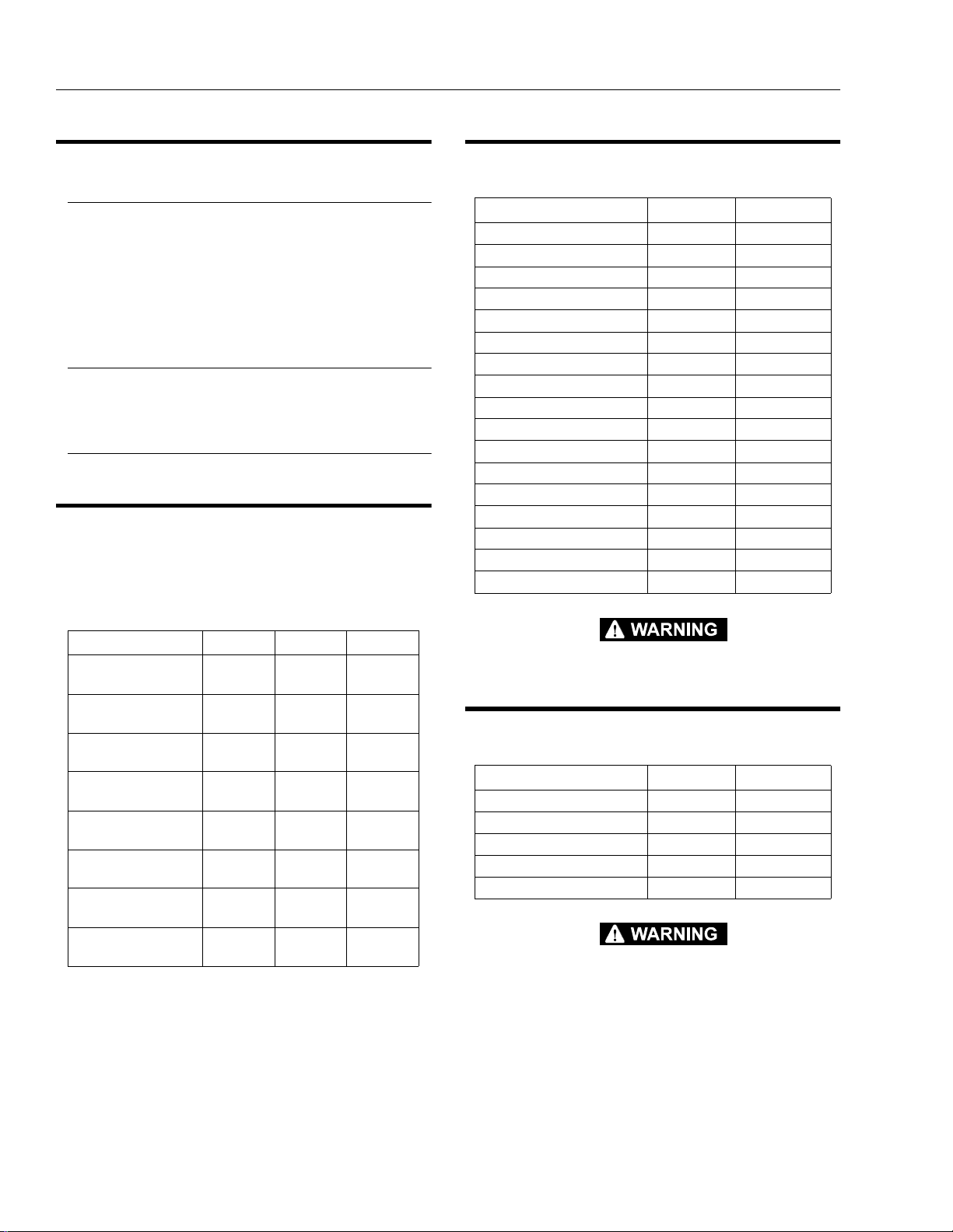
1.6 TORQUE SPECIFICATIONS
Table 1-1.Torque Requirements
Description Torque V alue Interval Hours
Wheel Lugs 170 ft. lbs.
(230 Nm)
Swing Bearing
(Dry)
Swing Bearing
((Loctite)
* Check swing bearing bolts for security after first
50 hours of operation and every 600 hours thereafter.
220 ft. lbs.
(298 Nm)
240 ft. lbs.
(326 Nm)
150
50/600*
50/600*
1.7 LUBRICATION
Hydraulic Oil
Table 1-2.Hydraulic Oil
Hydraulic System
Operating
Temperature Range
+0 to + 180 F
(-18 to +83 C)
+0 to + 210 F
(-18 to +99 C)
+50 to + 210 F
(+10 to +99 C
NOTE: Hydraulic oils must have anti-wear qualities at least
to API Service Classification GL-3, and sufficient
chemical stability for mobile hydraulic system service.
Aside from JLG recommendations, it is not advisable
to mix oils of different brands or types, as they may
not contain the same required additives or be of
comparable viscos ities. If use of hydraulic oil ot her
than Mobil DTE 11M is desired, contact JLG Industries for proper recommendations.
S.A.E. Viscosity
Grade
10W
10W-20, 10W30
20W-20
Lubrication Specifications
Table 1-3.Lubrication Specifications.
KEY SPECIFICATIONS
MPG Multipurpose Grease having a minimum dripping point of
350 degrees F. Excellent water resistance and adhesive
qualities; and being of extreme pressure type (Timken OK
40 pounds minimum).
EPGL Extreme Pressure Gear Lube (oil) meeting API Service
Classification GL-5 or Mil-Spec Mil-L-2105.
HO Hydraulic Oil. Mobil DTE-11M
OG* Open Gear Lube - Tribol Molub-Alloy 936 Open Gear Com-
pound. (JLG Part No. 3020027)
BG* Bearing Grease (JLG Part No. 3020029) Mobilith SHA 460.
LL Synthetic Lithium Lubricant, Gredag 741 Grease. (JLG
Part No. 3020022)
EO Engine (crankca se) Oil. Gas - API SF/SG cl ass, MIL-L-
2104. Diesel - API CC/CD class, MIL-L-2104B/MIL-L2104C.
*MPG may be substituted for these lubricants, if necessary, but service intervals will be reduced.
NOTE: Refer to Lubrication Chart, Figure1-2, for specific
lubrication procedures.
Table 1-4. Mobil DTE 11M Specs
ISO Viscosity Grade #15
Gravity API 31.9
Pour Poi nt, Max -40 F (-40 C)
Flash Point, Min. 330 F (166 C)
Viscosity
at 40° C 15 cSt
at 100° C 4.1 cSt
at 100° F 80 SUS
at 210° F 43 SUS
cp at -30° F 3.200
Viscosity Index 140
3120884 – JLG Lift – 1-3
SECTION 1 - SPECIFICATIONS
Table 1-5.Cylinder Specifications
Cylinder Bore Stroke Rod Dia.
Upper Lift
Cylinder
3.00
(76.2)
28.3125
(719.1)
1.50
(38.1)
Mid Lift Cylinder 3.00
(76.2)
21.25
(539.7)
1.50
(38.1)
Lower Lift Cylinder 4.00
(101.6)
23.25
(590.5)
2.25
(57.1)
T elescope Cylinder 2.00
(50.8)
92
(2337)
1.25
(31.8)
Master Cylinder 2.00
(50.8)
9.375
(238.1)
1.00
(25.4)
Slave Cylinder 2.00
(50.8)
9.375
(238.1)
1.00
(25.4)
Rotator Cylinder 1.875
(47.6)
15.250
(387.3)
1.00
(25.4)
Steer Cylinder
(Double Rod)
2.50
(63.5)
4.06
(103.1)
1.75
(44.5)
1.8 PRESSURE SETTINGS
Main Valve
Upper Lift Down Relief - 38 bar (550 psi)
Mid/Lower Lift Down Relief - 117 bar (1700 psi)
Telescope In Relief - 148 bar (2150 psi)
Platform Level Up Relief - 172 bar (2500 psi)
Platform Level Down Relief - 83 bar (1200 psi)
Steer/Brake Valve
Steer Relief - 159 bar (2300 psi)
Main Relief - 221 bar (3200 psi)
Jib Valve
Jib Relief (Up and Down) - 103 bar (1500 psi)
1.9 CYLINDER SPECIFICATIONS
NOTE: All dimensions are given in inches (in.), with the met-
ric equivalent, millimeters (mm), given in parentheses.
1.10 MAJOR COMPONENT WEIGHTS
Table 1-6.Major Component Weights
Component LB. KG.
Platform and Support 215 97.5
Upper Boom Complete 810 367
Mid Boom Complete 550 249
Lower Boom Complete 550 249
Upper Lift Cylinder 89 40
Mid Lift Cylinder 95 43
Lower Lift Cylinder 110 50
T elescope Cy linder 85 38 .5
Upper Upright 225 102
Lower Uprig ht 97 44
Turntable 948 430
Battery Box (incl. batteries) 600 272
Chassis (w/ pneu. tires) 4,295 1948
Chassis (w/ foam-filled tires) 4,695 2130
Counterweight 3850 1746
Machine Complete (E45A) 14,000 6356
Machine Complete (M45A) 14,300 6492
SELECT LIFTING EQUIPMENT WITH CAPACITY CAPABLE OF
SAFELY SUPPORTING WEIGHT.
1.11 CRITICAL STABILITY WEIGHTS
Table 1-7.Critical Stability Weights
Component LB. KG.
Counterweight 3850 1746
Tire & Wheel (foam-filled) 207 94
Platform (4ft [1.2 m]) 90 41
1-4 – JLG Lift – 3120884
Platform (5 ft. [1.5 m]) 100 45
Battery (each) 120 54
DO NOT REPLACE ITEMS CRITICAL TO STABILITY WITH ITEMS
OF DIFFERENT WEIGHT OR SPECIFICATION (FOR EXAMPLE:
BATTERIES, FILLED TIRES, PLATFORM) DO NOT MODIFY UNIT
IN ANY WAY TO AFFECT STABILITY.

SECTION 1 - SPECIFICATIONS
1.12 SERIAL NUMBER LOCATIONS
For machine identification, a serial number plate is affixed
to the left rear of frame, in front of left rear wheel. If the
serial number plate is damaged or missi ng, the machine
serial number is stamped on the top left side of the frame
and the top left side of the turntable. In addition, the serial
number is stamped on top of the end of the upper boom,
mid boom, and lower boom at the left rear of the booms.
Figure 1-1. Serial Number Locations
3120884 – JLG Lift – 1-5

SECTION 1 - SPECIFICATIONS
Figure 1-2. Lubrication Diagram
1-6 – JLG Lift – 3120884

Table 1-8. Lubrication Chart
SECTION 1 - SPECIFICATIONS
Interval Hours
3 Months
150 hrs
6 Months
300 hrs
1 Year
600 hrs
2 Years
1200 hrs
Comments
Components
Number/Type
Lube Points
Capacity Lube
Lubrication
Swing Bearing
1
Swing Bearing /
2
Worm Gear Teeth*
Hydraulic Fluid (Oil)
3
Hydraulic Filter
4
Wheel Drive Hub
5
Wheel Bearing
6
Spindles/Bushing
7
Boom Pivot Pins/
8
Bushing
Engine
9
NOTES: KEY TO LUBRIC ANTS
Lubrication intervals are base d on machine operation under nor mal conditions. For machines used in multi shift operations and/or ex posed to hostile
environments or conditions, l ubrication frequencies must be increased accordingly .
* If necessary install grease fitt ings into worm gear housing and grease bea rings.
1 Grease Fittin g or by
brush
Spray On A/R Mobiltac
Fill Cap 15 liters (tank) HO X Check o il every 10 hou rs of operation.
N/A N/A N/A X Replace filter element after first 50 hours and
Fill Plug/Hal f Full 0.5 liter (1/2 Full) EPGL X Check o il level at side plug on hub dail y.
Repack A/R MPG X
N/A A/R LL At Spindle/Bushing Repl acement Coat I.D. of bushings pri or to installin g king
N/A A/R LL At boom pivot pin s/bushing re placement Coat I.D. of bushi ngs prior to in stalling pins.
Fill Cap R efer to Engi ne
A/R MPG X More freq uent lubricati on intervals may b e
X More freq uent lubricati on intervals may be
375NC
EO Check daily . Change in acco rdance with
Manual
EPGL
required
required.
Change oil every 1 200 hours of opera tion.
every 300 hours t hereafter .**
Change after fir st 150 hours then e very 1200
hours of operatio n.
pins.
engine manual.
EO
Engine Oil
Extreme Pressure Ge ar Lube
HO
Hydraulic Fluid (Mobil DTE-11M)
MPG
Multi-Purpose Gre ase
Synthetic Lithiu m Lubricant
LL
DO NOT OVERGREASE BEARINGS. OVERGREASING BEARINGS WILL RESULT IN
BLOWING OUTER SEAL IN HOUSING.
** Under certain conditions, it may be necessary to replace the h ydraulic filter on a more frequent basis. A common symptom of a dirty filter is sluggishness experienced in hydraulic func tions.
3120884 – JLG Lift – 1-7
SECTION 1 - SPECIFICATIONS
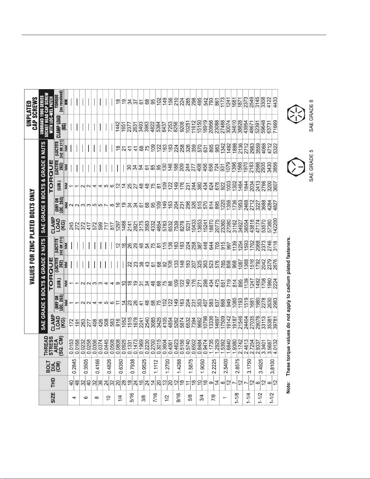
Figure 1-3. Torque Chart
1-8 – JLG Lift – 3120884

SECTION 2. PROCEDURES
SECTION 2 - PROCEDURES
2.1 GENERAL
This section provides information necessary to per form
maintenance on the aerial platform. Descriptions, techniques and specific procedures are designed to provide
the safest and most efficient maintenance for use by personnel responsible for ensuring the correct installation
and operation of machine components and systems.
WHEN AN ABNORMAL CONDITION IS NOTED AND PROCEDURES
CONTAINED HEREIN DO NOT SPECIFICALLY RELATE TO THE
NOTED IRREGULARITY, WORK SHOULD BE STOPPED AND
TECHNICALLY QUALIFIED GUIDANCE OBTAINED BEFORE WORK
IS RESUMED.
The maintenance procedures included consist of servicing and component rem oval and installation, disassembly,
and assembly, inspection, lubrication and cleaning. Information on any special tools or test equipment is also provided where applicable.
2.2 SERVICING AND MAINTENANCE
GUIDELINES
General
The following inf ormation is prov ided to a ssist you in t he
use and application of servicing and maintenance procedures contained in this chapter.
Safety and Workmanship
Your safety and that of others is the first consideration
when engaging in the maintenance of equipment. Always
be conscious of weight. Never atte mpt to move heavy
parts without the aid of a mechanical device. Do not allow
heavy objects to rest in an unstable position. When raising
a portion of the equipment, ensure that adequate support
is provided.
and fittings themselves. As soon as a line or component is disconnected, cap or cover all openings to
prevent entry of foreign matter.
3. Clean and inspect all parts during servicing or maintenance, and assure that all passages and openings
are unobstructed. Cover all parts to keep them
clean. Be sure all parts are clean before they are
installed. New parts should remain in their containers until they are ready to be used.
Component Removal and Installation
1. Use adjustable lifting devices, whenever possible, if
mechanical assistance is required. All slings (chains,
cables, etc.) should be parallel to each other and as
near perpend icular as possibl e to top of par t being
lifted.
2. Should it be necessary to remove a c omponent on
an angle, keep in mind that the capacity of an eyebolt or similar bracket lessens, as th e an gle between
the supporting structure and the component
becomes less than 90 degrees.
3. If a part resists removal, check to see whether all
nuts, bolts, cables, brackets, wiring, etc. have been
removed and that no adjacent parts are interfering.
Component Disassembly and Reassembly
When disassembling or r e assembling a compon ent, complete the procedural steps in sequence. Do not part ially
disassemble or assemble one part, then start on another.
Always recheck your work to assure that nothing has been
overlooked. Do not make any adjustments, ot her than
those recommended, without obtaining proper approval.
Pressure Fit Parts
When assembling pressure fit parts, use an “anti-seize” or
molybdenum disulfid e base co mpound to l ubricate the
mating surface.
Cleanliness
1. The most important single item in preserving the
long service life of a machine is to keep dirt and foreign materials out of the vital components. Precautions have been taken to safeguard against this.
Shields, covers, seals and filters are provided to
keep oil supplies clean; however, these items must
be maintained on a s chedu led ba sis i n o rder to func tion properly.
2. At any time when hydraulic oil lines are disconnected, clear adjacent areas as well as the openings
3120884 – JLG Lift – 2-1

SECTION 2 - PROCEDURES
Bearings
1. When a bearing is removed, cover it to keep out dirt
and abrasives. Clean bearings in nonflammable
cleaning solvent and allow to drip dry. Compressed
air can be used but do not spin the bea ring.
2. Discard bearings if the races and balls (or rollers)
are pitted, scored or burned.
3. If bearing is found to be serviceable, apply a light
coat of oil and wrap it in clean (waxed) paper. Do not
unwrap reusable or new bearings until they are
ready to be installed.
4. Lubricate new or used serviceable bearings before
installation. When pressing a bearing into a retainer
or bore, apply pressure to the outer race. If the bearing is to be in sta lled on a sh aft, apply pres su re to the
inner race.
Gaskets
Check that holes in gaskets align with openings in the
mating parts. If it becomes necessary to hand fabricate a
gasket, use gasket material or stock of equivalent material
and thickness. Be sure to cut holes in the right location as
blank gaskets can cause serious system damage.
Bolt Usage and Torque Application
1. Use bolts of proper length. A bolt which is too long
will bottom before the head is tight against its related
part. If a bolt is too short, there will not be enough
thread area to engage and hold the part properly.
When replacing bolts, use only those having the
same specifications of the original, or one which is
equivalent.
Hydraulic Lines and Electrical Wiring
Clearly mark or tag hydraulic lines and electrical wiring, as
well as their receptacles, when discon nec ting or removing
them from the unit. This will assure that they are correctly
reinstalled.
Hydraulic System
1. Keep the system clean. If evidence of metal or rubber particles are found i n the hydraulic system, drain
and flush the entire system.
2. Disassemble and reassemble parts on clean work
surface. Clean all metal parts with non-flammable
cleaning solvent. Lubricate components, as
required, to aid assembly.
Lubrication
Service applicable components with the amount, type,
and grade of lubricant recommended in this man ual, at
the specified interval. When recommended lubricants are
not available, consult your local supplier for an equivalent
that meets or exceeds the specifications listed.
Batteries
Clean batteries using a non-metallic brush and a solution
of baking soda and water. Rinse with clean water. After
cleaning, thoroughly dry batteries and coat terminals with
an anti-corrosion compound.
Lubrication and Servicing
Components and assemblies requiring lubrication and
servicing are shown in Lubricati on Chart.
2. Unless specific torque requirements are given within
the text, standard torque values should be used on
heat treated bolts, studs and steel nuts, in accordance with recommended shop practices.
2-2 – JLG Lift – 3120884

SECTION 2 - PROCEDURES
2.3 LUBRICATION INFORMATION
Hydraulic System
1. The primary enemy of a hydraulic system is contamination. Contaminants enter the system by various
means, e.g.; inadequate hydr aulic oil, allowi ng moisture, grease, filings, sealing componen ts, sand, etc.
to enter when performing maintenance, or by permitting the pump to cavitate due to insufficient system warm-up.
2. The design and manufacturing tolerances of the
component working parts are very close, therefore,
even the smallest amount of dirt or foreign matter
entering a system can cause wear or damage to the
components and generally results in faulty operation. Every precaution must be taken to keep
hydraulic oil clean, including reserve oil in storage.
Hydraulic system filters should be checked,
cleaned, and/or replaced at the specified intervals
required in Section 1. Always examine filters for evidence of metal particles.
3. Cloudy oils indicate a high moisture content which
permits organic gr ow t h, res ulting in oxidation or corrosion. If this conditi on occurs, the system mu st be
drained, flushed, and refilled with clean oil.
4. It is not advisable to mix oils of different brands or
types, as they may not contain the same required
additives or be of comparable viscosities. Good
grade mineral oils, with viscosities suited to the
ambient temperatures in which the machine is operating, are recommended for use.
NOTE: Metal particles may appear in the oil or filters of new
machines due to the wear-in of meshing components.
Hydraulic Oil
1. Refer to Section 1 for recommendations for viscosity
ranges.
2. JLG recommends Mobil DTE-11 Hydra ulic O il, wh ich
has an SAE viscosity of 10W and a viscosity index of
140.
NOTE: Start-up of hydraulic system with oil temperatures
below -29 degrees C. is not recommended. If it is
necessar y to sta r t the sy ste m in a sub- zero envi ron ment, it will be necessary to heat the oil with a low
density 100VAC heater to a minimum temperature of
-29 degrees C.
sesses the same antiwear and rust protection ch aracteristics as mineral oils, but will not adversely
affect ground water or the environment when spilled
or leaked in small amounts. Mobil EAL224H has a
viscosity of 34 cST at 40° C and a viscosity index of
213. The operating range of this oil is -18° C to +83°
C.
IT IS RECOMMENDED THAT MOBIL EAL224H HYDRAULIC OIL BE
STORED ABOVE FREEZING (0 C) AS THE OIL MAY APPEAR
CLOUDY AFTER EXPOSURE TO LOW TEMPERATURES FOR
EXTENDED PERIODS OF TIME. THE CLOUDINESS WILL DISAPPEAR
WHEN THE OIL IS WARME D TO AT L EAST 1 0 C AND AG ITATED. DO
NOT ATTEMPT TO "THIN" THE OIL WITH NO.2 DIESEL FUEL. FOR
BEST RESULTS, STORE THE OIL ABOVE FREEZING.
NOTE: Accidentally mixing Mobil EAL224 H hydraulic oil wi th
other mineral oils will cause no loss of performance
characteristics. However, biodegradability may be
reduced and toxicity may be increased, depending
on the oil and level of contamination.
Changing Hydraulic Oil
1. Use of any of the recommended hydraulic oils eliminates the need for changing the oil on a regular
basis. However, filter elements must be changed
after the first 50 hours of operation and every 300
hours thereafter. If it is necessary to change the oil,
use only those oils meeting or ex ceeding the specifications appearing in this manual. If unable to obtain
the same type of oil supplied with the machine, consult local supplier for assistance in selecting the
proper equivalent. Avoid mixing petroleum and synthetic base oils. JLG Industries recommends ch an ging the hydraulic oil every two years.
2. Use every precaution to keep the hydraulic oil clean.
If the oil must be poured from the original container
into another, be sure to clean all possible contaminants from the service container. Always clean the
mesh element of the filter and replace the cartridge
any time the system oil is changed.
3. While the unit is shut dow n, a good preventive maintenance measure is to make a thorough inspection
of all hydraulic components, lines, fittings, etc., as
well as a functional check of each system, before
placing the machine back in service.
3. Some machines may be specially equipped with
Mobil EAL224H biodegradable and non-toxic
hydraulic oil. This oil is vegetable oil based and pos-
3120884 – JLG Lift – 2-3
SECTION 2 - PROCEDURES
Lubrication Specifications
Specified lubricants, as recommended by the component
manufacturers, are always th e best choice, however,
multi-purpose greases usually have the qualities which
meet a variety of single purpose requirements. Should
any question arise regarding the use of greases in maintenance stock, consul t your local supp lier for eval uation.
Refer to Section 1 for an expl anation of the lub ricant ke y
designations appearing in the Lubrication Chart.
2.4 BATTERY MAINTENANCE AND
CHARGING
Battery Maintenance, Qu arterly
1. Open battery compartment cover to allow access to
battery terminals and vent caps.
WHEN ADDING WATER TO BATTERIES, ADD WATER UNTIL ELECTROLYTE COVERS PLATES. DO NOT CHARGE BATTERIES
UNLESS ELECTROLYTE COVERS THE PLATES.
NOTE: When adding distilled water to batteries , no n-metalli c
containers and/or funnels must be used.
To avoid electrolyte overflow, add distilled water to
batteries after charging.
When adding water to the battery, fill only to level
indicated or 9.5 mm above separators.
3. Remove battery cables from each battery post one
at a time, negative first. Clean cables with acid neutralizing solution (e.g. baking soda and water or
ammonia) and wire brush. Replace cables and/or
cable clamp bolts as re quired.
4. Clean battery post with wire brush then re-connect
cable to post. Coat non-contact surfaces with mineral grease or petroleum jelly.
5. When all cables and terminal posts have been
cleaned, ensure all cables are properly positioned
and do not get pinched. Close battery compartment
cover.
6. Start hydraulic system and ensure that it functions
properly.
Optional On Board Generator
EXHAUST GAS HAZARD. RUN THE GENERATOR IN A WELL VENTILATED AREA ONLY.
WHEN THE GENERATOR EN ABLE CONTROL LOCATED IN T HE
PLATFORM CONTROL BOX IS IN THE ON POSITION AND THE
GROUND EMERGENCY STOP SWITCH IS ON (PULLED OUT), THE
GENERATOR WILL START AUTOMATICALLY WHEN THE BATTERIES REACH A LOW-CHARGE STATE, AUTOMATICALLY
CHARGING THE BATTERIES. THE GENERATOR WILL A LSO
AUTOMATICALLY STAR T IF THE G ENERATOR ST ART BATTERY
IS LOW.
2. Remove all vent caps and inspect electrolyte level of
each cell. Electrolyte level should be to the ring
approximately one inch from top of battery. Fill batteries with distilled water only. Replace and secure
all vent caps.
2-4 – JLG Lift – 3120884

SECTION 2 - PROCEDURES
Figure 2-1. On Board Generator
3120884 – JLG Lift – 2-5
SECTION 2 - PROCEDURES
NOTE: The engine will automatically shut down under the
following conditions:
High Engine Oil Temperature
Low Engine Oil Pressure
Engine Overspeed
Generator Overvoltage
Batteries fully charged
TO AVOID INJURY FROM AN EXPLOSION, DO NOT SMOKE OR
ALLOW SPARKS OR A FLAME NEAR BATTERY DURING SERVICING. ALWAYS WEAR EYE AND HAND PROTECTION WHEN SERVICING BATTERIES.
Battery Charging (On Board Charger)
1. For maximum battery life:
a. Avoid completely discharging the batteries.
b. Fully charge the batteries each day the machine
is used.
c. Charge the batteries at available times between
charging.
d. Be sure the battery fluid covers the battery
plates before charging, but to avoid overflow, do
not top off the fluid level until charging.
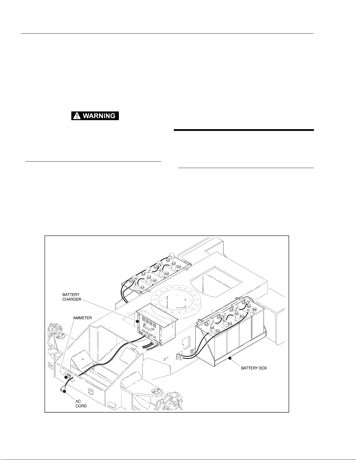
2. To charge the batteries, connect the charger to a
115 volt source with a 15 amp minimum capacity.
3. The Charger will shut off automatically when the batteries are fully charged.
4. The charge cycle is complete when the ammeter
reads 0 amps. Any reading indicates the charge
cycle is not complete.
5. Depleted batteries will take approximately 17 hours
to charge.
2.5 CYLINDERS - THEORY OF OPERATION
Upper Boom Lift, Mid Boom Lift, Lower
Boom Lift, T e lescope, Slave, Master , Rotator,
and Steer
A double acting cylinder is one that requires oil flow to
operate the cylinder rod in both directions. Directing oil
(by actuating the corresponding control valve to the piston side of the cylinder) forces the piston to travel toward
the rod end of the barrel, extending the cylinder rod (piston attached to rod). When the oil flow is stopped, movement of the rod will stop. By directing oil to the rod side of
the cylinder, the piston will be forced in the opposite direction and the cylinder rod will retract.
Figure 2-2. Batteries and Battery Charger
2-6 – JLG Lift – 3120884

Holding valves are used in the Lift circuits to prevent
retraction of the cylin der rod should a hydr aulic line rupture or leak develop between t he cylin der and it s relat ed
control valve.
2.6 CYLINDER CHECKING PROCEDURES
NOTE: Cylinder checks must be performed any time a cylin-
der component is repl ac ed o r wh en im pro pe r syste m
operation is suspected.
Cylinder Without Counterbalance Valves
(Steer, Master, and Rotate)
1. Using all applicable safety precautions, activate
hydraulic system and fully extend cylinder to be
checked. Shut down hydraulic system.
2. Carefully disconnect hydraulic ho se from retra ct port
of cylinder. There will be initial weeping of hydraulic
fluid which can be caught in a suitable container.
After initial discharge, there should be no further
leakage from the retract port.
3. Activate hydraulic system, and activate cylinder
extend function.
4. If cylinder retract port leakage is less than 6-8 drops
per minute, carefully reconnect hose to retract port
and retract cylinder. If leakage continues at a rate of
6-8 drops per minute or more, cylinder repairs must
be made.
5. With cylinder fully retracted, shut down motor and
carefully disconnect hydraulic hose from cylinder
extend port.
6. Activate hydraulic system and activate cylinder
retract function. Check extend port for leakage.
7. If extend port leakage is less than 6-8 drops per
minute, carefully reconnect hose to extend port,
then activate cylinder through one complete cycle
and check for leaks. If leakage continues at a rate of
6-8 drops per minute or more, cylinder repairs must
be made.
Cylinders With Single Counterbalanc e Valve
(Upper Lift Cylinder)
SECTION 2 - PROCEDURES
WHEN WORKING ON THE UPPER BOOM LIFT CYLINDER RAISE
THE UPPER BOOM TO HORIZONTAL AND PLACE A BOOM PROP
APPROXIMATELY 2.5 CM BELOW THE MAIN BOOM. IF WORKING
ON LOWER BOOM LIFT CYLINDER, RAISE LOWER BOOM HALFWAY, FULLY ELEVATE UPPER BOOM AND ATTACH OVERHEAD
CRANE TO THE UPRIGHT FOR SUPPORT, LEAVING APPROXIMATELY 2.5 CM OF SLACK IN CHAIN O R SLING FOR TEST PURPOSES.
2. After completing the above, shut down hydraulic
system and allow machine to si t for 10-15 minutes.
This is done to relieve pressure in the hydraulic
lines. Carefully remove hydraulic hoses from appropriate cylinder port block.
3. There will be initial weeping of hydraulic fluid, which
can be caught in a suitable container. After the initial
discharge, there should not be any further leakage
from the ports. If leakage continues at a rate of 6-8
drops per minute or more, the following cylinder
repairs must be made. If the retract port is leaking,
the piston is leaking, the piston seals are defective
and must be replaced. If the extend port is leaking,
the counterbalance is defective and must be
replaced.
4. If no repairs are necessary or when repairs have
been made, carefully reconnect hydraulic hoses to
the appropriate ports.
5. Remove boom prop/overhead crane, activate
hydraulic sy s t e m and run cyl inder throug h complete
cycle to check for leaks and operation.
Cylinders With Dual Counterb alance Valve
(Lower Lift, Mid Lift, Telescope, and Sla ve
Cylinders)
OPERATE ALL FUNCTIONS FROM GROUND CONTROL STATION
ONLY.
1. Using all applicable safety precautions, activate
hydraulic system.
WHEN WORKING ON THE UPPER BOOM LIFT CYLINDER RAISE
THE UPPER BOOM TO HORIZONTAL AND PLACE A BOOM PROP
OPERATE ALL FUNCTIONS FROM GROUND CONTROL STATION
ONLY.
1. Using all applicable safety precautions, activate
hydraulic system.
APPROXIMATELY 2.5 CM BELOW THE MAIN BOOM. IF WORKING
ON LOWER BOOM LIFT CYLINDER, RAISE LOWER BOOM HALFWAY, FULLY ELEVATE UPPER BOOM AND ATTACH OVERHEAD
CRANE TO THE UPRIGHT FOR SUPPORT, LEAVING APPROXIMATELY 2.5 CM OF SLACK IN CHAIN O R SLING FOR TEST PURPOSES.
3120884 – JLG Lift – 2-7

SECTION 2 - PROCEDURES
2. When working on the platform slave cylinder, stroke
platform slave level cylinder forward until platform
sits at a 45 degree angle.
3. After completing the above, shut down hydraulic
system and allow machine to sit f or 10-15 minutes.
This is done to relieve pressure in the hydraulic
lines. Carefully remove hydraulic hoses from appropriate cylinder port block.
4. There will be initial weeping of hydraulic fluid, which
can be caught in a suitable container. After the initial
discharge, there should not be any further leakage
from the ports. If leakage continues at a rate of 6-8
drops per minute or more, the following cylinder
repairs must be made. If the retract port is leaking,
the piston is leaking, the piston seals are defective
and must be replaced. If the extend port is leaking,
the counterbalance is defective and must be
replaced.
5. To check piston seals, carefully remove the counterbalance valve from the retract port. After initial discharge there should not be any further leakage from
the ports. If leakage occurs at a rate of 6-8 drops per
minute or more, the piston seals are defective and
must be replaced.
6. If no repairs are necessary or when repairs have
been made, carefully reconnect hydraulic hoses to
the appropriate ports.
7. Remove boom prop/overhead crane, activate
hydraulic system and run cylinder through complete
cycle to check for leaks and operation.
source. Adequa te ly s upport the cylinder rod, if applicable.
3. If applicable, remove the cartridge-type holding
valve and fittings from the cylinder port block. Discard o-rings.
4. Place the cylinder barrel into a suitable holding fixture.
Figure 2-3. Cylinder Barrel Support
5. Mark cylinder head and barrel with a center punch
for easy realignment. Using an allen wrench, loosen
the cylinder head retainer cap screws, and remove
cap screws from cylinder barrel.
2.7 CYLINDER REPAIR
NOTE: The following are general procedures that apply to
all of the c ylinde rs on th is mac hine. Pr ocedur es that
apply to a specific cylinder will be so noted.
Disassembly
DISASSEMBLY OF THE CYLINDER SHOULD BE PERFORMED ON
A CLEAN WORK SURFACE IN A DIRT FREE WORK AREA.
1. Connect a suitable auxiliary hydraulic power source
to the cylinder port block fitting.
DO NOT FULLY EXTEND CYLINDER TO THE END OF STROKE.
RETRACT CYLINDER SLIGHTLY TO AVOID TRAPPING PRESSURE.
2. Operate the hydraulic power source and extend the
cylinder. Shut down and disconnect the power
NOTE: St eps 6 applies only t o the lower lift and tele scope
6. Using a spanner wrench, loosen the end cap or
7. Attach a suitable pulling device to the cylinder rod
2-8 – JLG Lift – 3120884
Figure 2-4. Capscrew Removal
cylinders.
head retainer, and remove from cylinder barrel.
port block end or cylinder rod end, as applicable.

EXTREME CARE SHOULD BE TAKEN WHEN REMOVING THE CYLINDER ROD, HEAD, AND PISTON. AVOID PULLING THE ROD OFFCENTER, WHICH COULD CAUSE DAMAGE TO THE PISTON AND
CYLINDER BARREL SURFACES.
8. With the barrel clamped securely, apply pressure to
the rod pulling device and carefully withdraw the
complete rod assembly from the cylinder barrel.
SECTION 2 - PROCEDURES
12. Remove the bushing from the piston.
Figure 2-6. Tapered Bushing Removal
13. Screw the piston CCW, by hand, and remove the
piston from cylinder rod.
14. Remove and discard the piston o-rings, seal rings,
and backup rings.
Figure 2-5. Cylinder Rod S upport
9. Using suitable protection, clamp the cylinder rod in
a vise or similar holding fixture as close to the piston
as possible.
10. Loosen and remove the cap screw(s), i f applicable,
which attach the tapered bushing to the piston.
11. Insert the cap screw(s) in the threaded holes in the
outer piece of the tapered bushing. Progressively
tighten the cap screw(s) until the bushing is loose
on the piston.
15. Remove piston spa cer, if applicable, from the rod.
16. Remove the rod from the holding fixture. Remove
the cylinder head gland an d retainer plate, if app licable. Discard the o-rings, back-up rings, rod seals,
and wiper seals.
Cleaning and Inspection
1. Clean all parts thoroughly in an approved cleaning
solvent.
2. Inspect the cylinder rod for scoring, tapering, ovality,
or other damage. If necessary, dress rod with
Scotch Brite or equivalent. Replace rod if necessary.
3. Inspect threaded portion of rod for excessive damage. Dress threads as necessary.
4. Inspect inner surface of cylinder barrel tube for scoring or other damage. Check inside diameter for
tapering or ovality. Replace if necessary .
5. Inspect threaded portion of b arrel fo r dam age. Dress
threads as necessary.
6. Inspect pist on surface f or damage and s coring and
for distortion. Dress piston surface or replace piston
as necessary.
7. Inspect threaded portion of piston for damage.
Dress threads as necessary.
8. Inspect seal and o-ring grooves in piston for burrs
and sharp edges. Dress applicable surfaces as necessary.
3120884 – JLG Lift – 2-9

SECTION 2 - PROCEDURES
Figure 2-7. Gar-Max Bearing Installation
9. Inspect cylinder head inside diameter for scoring or
other damage and for ovality and tapering. Replace
as necessary.
10. Inspect threaded portion of head for damage. Dress
threads as necessary.
11. Inspect seal and o-ring grooves in head for burrs
and sharp edges. Dress applicable surfaces as necessary.
12. Inspect cylinder head outside diameter for scoring
or other damage and ovality and tapering. Replace
as necessary.
13. If applicable, inspect rod and barrel bearings for
signs of correct excessive wear or damage. Replace
as necessary.
a. Thoroughly clean hole, (steel bushing) of burrs,
dirt etc. to facilitate bearing installation.
b. Inspect steel bushing for wear or other damage.
If steel bushing is worn o r damaged, rod/bar rel
must be replaced.
c. Lubricate inside of the steel bushing with WD40
prior to bearing installation.
d. Using an arbor of the correct size, carefully
press the bearing into steel bushing.
Assembly
NOTE: Prior to cylinder assembly, ensure that the proper
cylinder seal kit is us ed . Se e your JLG Parts Manua l.
Apply a light film of hydraulic oil to all components
prior to assembly.
1. A speci al tool is use d to install a new rod seal into
the applicable cylinder head gland groove.
NOTE: Install pin into the Gar-Max bearing dry. Lubrication
is not required with nickel plated pins and bearings.
14. Inspect travel limiting collar or spacer for burrs and
sharp edges. If necessary, dress inside diameter
surface with Scotch Brite or equivalent.
15. If applic able, inspect port block fitt ings and holdi ng
valve. Replace as necessary.
16. Inspect the oil ports for blockage or the presence of
dirt or other foreign material. Repair as necessary.
17. If applicable, inspect piston rings for cracks or other
damage. Replace as nece s sa ry.
Figure 2-8. Rod Seal Installation
WHEN INSTALLING "POLY-PAK" PISTON SEALS, ENSURE SEALS
ARE INSTALLED PROPERLY. REFER TO WIPER SEAL INSTALLATION FOR CORRECT SEAL ORIENTATION. IMPROPER SEAL
INSTALLATION COULD RESULT IN CYLINDER LEAKAGE AND
IMPROPER CYLINDER OPERATION.
2. Use a soft mallet to tap a new wiper seal into the
applicable cylinder head gland groove. Install a new
wear ring into the applicable cylinder head gland
groove.
Figure 2-9. Wiper Seal Installation
2-10 – JLG Lift – 3120884

SECTION 2 - PROCEDURES
3. Place a new o-ring and back-up seal in the applicable outside diameter groove of the cylinder head.
Figure 2-10. Installation of Head Seal Kit
4. Install washer ring onto rod, careful ly instal l the head
gland on the rod, ensuring that the wiper and rod
seals are not damaged or dislodged. Push the head
along the rod to the rod end, as applicable.
5. Carefully slide the piston spacer on the rod.
6. If applicable, correctly place new o-ring in the inner
piston diameter gr oove. (The backup ring side facing the O-ring is grooved.)
7. If applicable, correctly place new seals and guide
lock rings in the outer piston diameter groove. (A
tube, with I.D. slightly larger than the O.D.of the piston is recommended to install the solid seal.)
NOTE: The backup rings for the solid seal have a radius on
one side. This side faces the solid seal.(See magnified insert in Figure 2-11.)The split of seals and
backup rings are to be positioned so as not to be in
alignment with each other.
Figure 2-11. Piston Seal Kit Installation
8. Using suitable protection, clamp the cylinder rod in
a vise or similar holding fixture as close to piston as
possible.
9. Carefully thread the piston on the cylinder rod hand
tight, ensuring that the o-ring and back-up rings are
not damaged or dislodged.
10. Thread piston onto rod until it abuts the spacer end
and install the tapered bushing.
NOTE: When installing the tapered bushing, piston and ma t-
ing end of rod must be free of oil.
WHEN REBUILDING THE STEER, LOWER LIFT, LEVEL CYLINDER,
OR UPPER LIFT CYLINDER, APPLY LOCTITE #242 TO TAPERED
BUSHING BOLTS, THEN TIGHTEN SECURELY.
3120884 – JLG Lift – 2-11
SECTION 2 - PROCEDURES
Figure 2-12. Tapered Bushing Installation
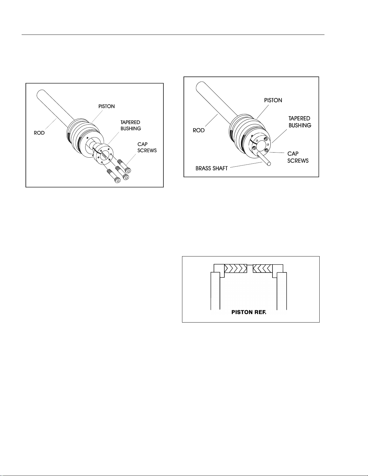
11. Assemble the tapered bushing loosely into the piston and insert JLG capscrews (not vendor capscrews) through the drilled holes in the bushing and
into the tapped holes in the piston.
12. Tighten the capscrews evenly and progressively in
rotation to the specified torque value. (See T able 2-1,
Cylinder Head and Tapered Bushing Torque Specifications.)
13. After the screws have been torqued, tap the tapered
bushing with a hammer (500 to 750 gram) and brass
shaft (approximately 19 mm in diameter) as follows;
b. Tap each space once; this means the tapered
bushing is tapped 3 times as there are 3 spaces
between the capscrews.
Figure 2-13. Seating the Tapered Bearing
14. Retorque the capscrews evenly and progressively in
rotation to the specified torque value. (See Table 2-1,
Cylinder Hea d an d Tapered Bushing Torque Specifications.)
15. Remove the cylinder rod from the holding fixture.
16. Place new guide locks and seals in the applicable
outside diameter grooves of the cylinder piston.
(See Figure 2-11., Piston Seal Kit Installation)
a. Place the shaf t against the cylinder rod and in
contact with the bushing in the spaces between
the capscrews.
Figure 2-14. Poly-Pak Piston Seal Installat ion
2-12 – JLG Lift – 3120884

SECTION 2 - PROCEDURES
17. Position the cylinder barrel in a suitable holding fixture.
EXTREME CARE SHOULD BE TAKEN WHEN INSTALLING THE
CYLINDER ROD, HEAD, A ND PISTON. AVOID PULLING TH E ROD
OFF-CENTER, WHICH COULD CAUSE DAMAGE TO THE PISTON
AND CYLINDER BARREL SURFACES.
18. With barrel clamped securely, and while adequately
supporting the rod, insert the piston end into the
barrel cylinder. Ensure that the piston loading o-ring
and seal ring are not damaged or dislodged.
19. Continue pushing the rod into the barrel until the cylinder head gland can be inserted into the barrel cylinder.
20. Secure the cylinder head gland using the washer
ring and socket head bolts.
Table 2-1.Cylinder Head and Tapered Bushing Torque
Specifications
Description
E.A.R. Cylinder
Level Cylinder (M45AJ)
Master Cylinder
(M45AJ)
Table 2-2. Cylinder Piston Nut Torque Specifications)
Description
Upper
Lift Cylinder
Mid
Lift Cylinder
Head Torque V alue
(Wet)
30 ft. lbs
(41 Nm)
30 ft. lbs
(41 Nm)
30 ft. lbs.
(41 Nm)
Nut Torque
Valve (Wet)
200 ft. lbs.
(270 Nm)
400 ft. lbs.
(542 Nm)
Tapered Bushing
Torque Value (Wet)
5 ft. lbs.
(7 Nm)
5 ft. lbs.
(7 Nm)
5 ft. lbs.
(7 Nm)
Setscrew
Torque Value
(Dry)
100 in. lbs.
(11 Nm)
100 in. lbs.
(11 Nm)
Figure 2-15. Rod Assembly Installation
21. After the cylinder has been reassembled, the rod
should be pushed all the way in (fully retracted) prior
to the reinstallation of any holding valve or valves.
22. If applicable, install the cartridge-type holding valve
and fittings in the rod port block, using new o-rings
as applicable. (See Table 2-3, Holding Valve Torque
Specifications).
IF THE CYLINDER IS TO BE TESTED PRIOR TO INSTALLATIO N ON
THE MACHINE, EXTREME CARE SHOULD BE USED TO INSURE
THAT THE OUTER END OF THE ROD IS SUPPORTED. USE
EITHER A TRAVELING OVERHEAD HOIST, FORK-LIFT, OR O THER
MEANS TO SUPPORT THE OVERHANGING WEIGHT OF THE
EXTENDING ROD.
Lower
Lift Cylinder
Level Cylinder (M45 A) 80 ft. lbs.
Master Cylinder
(M45A)
Table 2-3. Holding Valve Torque Specificatio ns
Description Torque Value
SUN - 7/8 HEX M20 X 1.5 THDS. 30-35 ft. lbs.
SUN - 1 1/8 HEX 1 -14 UNS THDS. 45-50 ft. lbs.
SUN - 1 1/4 HEX M36 X 2 THDS. 150-160 ft. lbs.
RACINE - 1 1/8 HEX 1 1/16 - 12 THDS. 50-55 ft. lbs.
RACINE - 1 3/8 HEX 1 3/16 - 12 THDS. 75-80 ft. lbs.
400 ft. lbs.
(542 Nm)
(108 Nm)
80 ft. lbs.
(108 Nm)
100 in. lbs.
(11 Nm)
100 in. lbs.
(11 Nm)
100 in. lbs.
(11 Nm)
(41-48 Nm)
(61-68 Nm)
(204-217 Nm)
(68-75 Nm)
(102-109 Nm)
RACINE - 1 7/8 HEX 1 5/8 - 12 THDS. 100-110 ft. lbs.
(136-149 Nm)
3120884 – JLG Lift – 2-13

SECTION 2 - PROCEDURES
Figure 2-16. Upper Boom Lift Cy linder Removal
2.8 CYLINDER REMOVAL AND
INSTALLATION
Upper (Main) Boom Lift Cylinder Removal
1. Place the machine on a flat and level surface. Place
the Upper Boom in a horizontal position. Place
Lower and Mid Booms 5 degree above horizontal.
Shut down machine and prop boom.
2. Tag, disco nnec t a nd ca p th e up per boom lift cylind er
hydraulic lines and ports.
3. Remove the hardware securing the cylinder rod
attach pin #1 to the boom. Using a suitable brass
drift, drive out the cylinder rod attach pin #1.
3. Remove cylinder port plugs and hydraulic line caps
and correctly attach lines to cylinder ports.
4. With function speed switch at its slowest setting,
extend the cylinder rod until attach pin hole aligns
with those in boom. Using a suitable drift, drive the
cylinder rod attach pin #1 through the aligned
holes. Secure the pin in place with pin retaining
hardware.
5. Cycle cylinder completely to check for proper functioning. Place boom in stowed position. Check
hydraulic fluid level and adjust accordingly.
Mid Boom Lift Cylinder Removal
1. Place machine on flat and level surface. Place the
Upper Boom in a horizontal position. Place the Mid
Boom in a 10 degree elevated position. Support
Upper Boom with a prop. Support upright with an
overhead cran e.
2. Using slings, restrain the lower lift cylinder.
3. Remove the hardware securing the cylinder rod
attach pin #3 to the boom. Using an appropriate
brass drift, drive out the cylinder rod attach pin #3.
4. Secure the cylinder with suitable slings or supports
as required. Remove the hardware securing the barrel end attach pin #2. Using a suitable brass drift,
drive out the barrel end attach pin #2.
5. Remove the cylinder from the boom and place in a
suitable work area.
Upper (Main) Boom Lift Cylinder In stallation
NOTE: Coat I.D. of bushings with specified lubricant prior to
installing pins.
1. Install Lift Cylinder in place using suitable slings or
supports, aligning attach pin mounting holes on
upright.
2. Using a suitable drift, drive the barrel end attach pin
#2 through the mounting holes in the lift cylinder
and upright. Secure in place with pin retaining hardware.
Figure 2-17. Mid Boom Lift Cylinder Removal
4. Tag, disconnect and cap the lift cylinder hydraulic
lines and ports.
5. Remove the hardware securing the barrel end attac h
pin #4 to the boom. Using an appropriate brass
drift, drive out the cylinder barrel pin #4.
6. Carefully remove cylinder from boom. Place in a
suitable work area.
2-14 – JLG Lift – 3120884

SECTION 2 - PROCEDURES
Mid Boom Lift Cylinder Installation.
NOTE: Co at I. D. of bushings wit h spe cif ied l ubr ic ant pr ior t o
installing pins.
1. With the booms positioned and supported, place
cylinder in position and secure in place using slings.
2. Install the cylinder barrel pin #4, being sure to align
the hole in the cylinder barrel pin with the retaining
pin screw hole. When holes alig n, in s t all hard ware.
3. Correctly install hydraulic lines to cylinder as previously tagged. Extend cylinder rod slowly until attach
pin hole aligns with those in boom.
4. Using a suitable brass drift, drive the cylinder rod
attach pin #3 through the aligned holes. Secure the
pin in place using retaining hardw are.
5. Remove boom prop and overhead crane. Take the
lift cylinder through one complete cycle to assure
correct functioning. Place boom in stowed position.
Check hydraulic fluid and adjust accordingly.
Lower Boom Lift Cylinder Removal
1. Place machine on flat and level surface. Place the
Upper Boom in a horizontal position. Place the Mid
and Lower Booms in a 10 degree elevated position.
Support Upper Boom with a prop. Support upright
with an overhead crane.
2. Using slings, restrain the lower lift cylinder.
4. Tag, disconnect and cap the lift cylinder hydraulic
lines and ports.
5. Remove the hardware securing the barrel end attac h
pin #6 to the boom. Using an appropriate brass
drift, drive out the cylinder barrel pin #6.
6. Carefully remove cylinder from boom. Place in a
suitable work area.
Lower Boom Lift Cylinder Installation
NOTE: Co at I. D. of bushings wi th spe cif ied lubr ic ant pr io r to
installing pins.
1. With the booms positioned and supported, place
cylinder in position and secure in place using slings.
2. Install the cylinder barrel pin #6, being sure to align
the hole in the cylinder barrel pin with the retaining
pin screw hole. When holes align, install hardwa re.
3. Correctly install hydraulic lines to cylinder as previously tagged. Extend cylinder rod slowly until attach
pin hole aligns with those in boom.
4. Using a suitable brass drift, drive the cylinder rod
attach pin #5 through the aligned holes. Secure the
pin in place using retaining hardware.
5. Remove boom prop and overhead crane. Take the
lift cylinder through one complete cycle to assure
correct functioning. Place boom in stowed position.
Check hydraulic fluid and adjus t acc ord ingly.
3. Remove the hardware securing the cylinder rod
attach pin #5 to the boom. Using an appropriate
brass drift, drive out the cylinder rod attach pin #5.
Figure 2-18. Lower Boom Lift Cylinder Removal
3120884 – JLG Lift – 2-15

SECTION 2 - PROCEDURES
Upper Boom Telescope Cylinder Removal
1. Place machine on flat and level surface, with Upper
Boom in the horizontal position. Extend Upper
Boom until fly attach pin #1 is accessible on fly.
Figure 2-19. Upper Telescope Cylinder Removal
2. Support Upper Boom basket end with a prop . Support Upper Upright end with an overhead cran e.
3. Tag, disconnect hydraulic li nes to telescop e cyli nder.
Use suitable container to retain any residual hydraulic fluid. Cap hydraulic lines and ports.
4. Remove the retaining rings that retain the telescope
cylinder rod to the fly boom.
5. Using a suitable brass drift, carefully drive the telescope cylinder rod pin #1 from the fly boom.
6. Remove the four (4) bolts securing the telescope
cylinder barrel end to the base boom.
NOTE: Care should be taken when removing the telescope
cylinder, do not leave cylinder rest on powertrack
which could cause damage to powertrack.
9. Using anoth er lifting device , support the rod end of
the cylinder and remove the cylinder from the boom
assembly.
10. Carefully lift the cylinder clear of the boom assembly
and lower to the ground or suitably supported work
area.
Upper Boom Telescope Cylinder Installation
1. Attach a hydraulic power supply to the telescope
cylinder ports. Using suitable supports or lifting
devices at each end of the cylinder, extend the rod
so that the cylinder pin attach holes are the same
distance apart as the boom pin attach holes.
2. Using suitable lifting equipment, carefully lower the
cylinder to the boom assembly.
3. Using anoth er lifting device , support the rod end of
the cylinder and install the cylinder into the boom
assembly.
4. Remove lifting devices from the telescope cylinder.
5. Carefully install the telescope cylinder rod pin #1
through the fly boom and secure it with the retaining
rings.
6. Carefully install the telescope cylinder barrel end to
base, securing cylinder to the base boom with four
(4) bolts and hardware.
7. Remove applicable hydraulic line and port caps and
correctly connect the hydraulic lines to the telescope cylinder. Ensure all hoses are correctly
routed.
8. Remove boom prop and overhead crane. Activate
hydraulic system.
9. Using all applicable safety precautions, operate the
boom functions. Check for correct operation and
hydraulic leaks. Secure as necessary.
10. Check fluid level of h ydrauli c tank a nd ad d as nec essary.
7. Using a suitable brass drift, carefully drive the telescope cylinder pin from the base boom.
8. Attach a suitable sling to the telescope cylinder.
Using a suitable lifting device attached to the sling
carefully pull the telescope cylinder from the boom
assembly.
2-16 – JLG Lift – 3120884

SECTION 2 - PROCEDURES
2.9 WEAR PADS
1. Shim up wear pads until snug to adjacent surface.
2. Replace wear pads when w orn to thickne ss shown
below.
2.10 BOOM MAINTENANCE
Removal
1. Remove the platform/support as follows:
a. Disconnect electrical cable from control con-
sole.
b. Using an overhead crane or suitable lifting
device, strap support the platform/support.
c. Remove hardware from pin #1. Using a suitable
brass drift and hammer, remove pin #1 from the
platform support.
d. Supporting the platform/support, remove the
hardware from pin #2. Using a suitable brass
drift and hammer, remove pin #2 from the fly
boom and remove the rotator.
e. Supporting the slave cylinder, remove the hard-
ware from pin #3. Using a suitable brass drift
and hammer, remove pin #3 from the fly boom.
f. Tag and disconnect hydraulic lines to the slave
leveling cylinder. Use a suitable container to
retain any residual hydraulic fluid. Cap hydraulic
lines and ports. Remove the slave cylinder.
2. Remove the boom from upright as follows:
Table 2-4. Wear Pad Thic kness
Pad
A 0.75" 19 mm 0.375" 9.5 mm
B 0.5" 13 mm 0.3125" 8 mm
C 0.5" 13 mm 0.3125" 8 mm
3. Adjust wear pads as follows:
a. Loosen jam nut on adjustment bolt, turn bolt CW
b. After adjustments have been made, tighten the
Thickness of
New Pad
Figure 2-20. Wear Pad Thickness
until wear pad is snug to adjacent surface.
jam nuts on wear pad bolts.
Replace When Worn to:
a. Remove hardware securing the cover plate on
the side of the base bo om section and remove
hose clamps. Disconnect wiring harness from
ground control harness connector.
HYDRAULIC LINES AND PORTS SHOULD BE CAPPED IMME DIATELY AFTER DISCONNECTING LINES TO AVOID ENTRY OF
CONTAMINANTS INTO SYSTEM.
b. Tag and disconnect hydraulic lines from boom
to control va lve. Use a s uitable conta iner to
retain any residual hydraulic fluid. Cap hydraulic
lines and ports.
c. Using a suitable lifting equipment, adequately
support boom weight along entire length.
3120884 – JLG Lift – 2-17

SECTION 2 - PROCEDURES
Figure 2-21. Platform Components and Attac h i ng Hardware (M45A & E45A)
2-18 – JLG Lift – 3120884

SECTION 2 - PROCEDURES
d. Remove hardware securing the lift cylinder pin
#1. Using a suitable bra ss drift and hammer,
remove pin #1 from the base boom.
e. Remove hardware securing the master cylinder
pin #2. Using a suitable brass drift and hammer,
remove pin #2 from the base boom.
f. Remove hardware securing the base boom pin
#3. Using a suitable bra ss drift and hammer,
remove pin #3 from the upright.
g. Using all applicable safety precautions, carefully
lift boom assembly clear of upright and lower to
ground or suitable supported work surface.
Disassembly Boom Sections
1. Loosen jam nuts on aft end of fly boom wear pad
adjustment and loosen adjustments.
2. Using a portable power source, attach hose to telescope cylinder port block. Using all applicable
safety precautions, activate hydraulic system and
extend cylinder to gain access to cylinder rod pin
#1. Shut down hydraulic system.
3. Carefully disconnect hydrau lic ho se from retrac t port
of cylinder. There will be init ial weepi ng of hydrau lic
fluid which can be caught in a suitable container.
After initial discharge, there should be no further
leakage from the retract port.
4. Remove hardware securing telescope cylinder #1 to
the fly boom section, then remove pin from fly.
5. Remove hardware securing telescope cylinder to
the base boom section.
WHEN REMOVING TELESCOPE CYLINDER FROM BOOM SECTIONS. CARE SHO ULD BE TAKEN NOT TO LET CY LINDER RES T
ON POWERTRACK WHICH COULD CA USE DAMAGE TO POWERTRACK.
Figure 2-22. Location of Componen ts - Boo m
Removal
6. Using a suitable lifting device, remove telescope cylinder from boom sections.
3120884 – JLG Lift – 2-19

SECTION 2 - PROCEDURES
7. Using a piece of tape, mark the length of hoses and
wires from front of fly boom and bottom of base
boom for reassembly.
8. Remove hardware securing the front cover on base
boom section.
9. Loosen jam nut s on front wear pad a dju st me nts and
loosen adjustments.
10. Remove hardware securing the front wear pads on
base boom section, remove wear pads.
11. Remove wire clamp on the inside of the fly nose.
12. Manually push the fly boom section into base boom
section to gain access to the powertrack attachment
bolts on the right side of the base boom secti on.
13. Remove hardware securing the powertrack to the aft
end of the fly boom section.
14. Using a suitable lifting device, remove fly boom from
boom section.
15. Remove hydraulic lines and electrical cables from
powertrack.
16. Remove hardware securing powertrack to the base
boom section. Remove powertrack.
Inspection
1. Inspect boom pivot pin for wear, scoring or other
damage, and for tapering or ovality. Replace pin as
necessary.
2. Inspect lift and master cylinder pins for wear, scoring
or other damage, and for tapering or ovality. Ensure
pin surfaces are protected prior to installation.
Replace pins as necessary.
3. Inspect telescope cylinder rod attach pin for wear,
scoring or other damage. Replace pin as necessary.
4. Inspect inner diameter of boom pivot bushings for
scoring, distortion, wear or other damage. Replace
bushings as necessary.
5. Inspect wear pads for wear as shown in Section 2.9,
Wear Pads.
6. Inspect all threaded components for damage such
as stretching, thread deformation, or twisting.
Replace as necessary.
7. Inspect structural units of boom assembly for bending, cracking, separation of welds, or ot her damage.
Replace boom sections as necessary.
Assembly
1. Install power track to the attach point on the inside
of the base boom section. Secure power track with
hardware.
2. Install hydraulic lines and electrical cables into the
power track.
3. Install wear pads to the aft end of the fly section.
4. Using suitable lifting equipment, slide fly section into
the base section until p ower trac k atta ch po int alig ns
with holes in side of base section.
5. Attach the power track to the aft end of fly boom
section. Secure power track with hardware.
2-20 – JLG Lift – 3120884

SECTION 2 - PROCEDURES
6. Using suitable lifting equipment, slide fly boom section out to gain access to telescope cylinder attach
pin hole.
7. Measure the distance between the telescope cylinder port block attach point on base boom section
and the attach point on fly boom section.
8. Connect a suitable auxiliary hydraulic power source
to the telescope cylinder port block.
9. Extend the telescope cylinder the distance of the
two attach points.
10. Secure the sling and lifting device at the telescope
cylinder’s approximate center of gravity, and lift the
cylinder to the aft end of the boom assembly.
WHEN INSERTING THE TELESCOPE CYLINDER INTO THE BOOM,
CARE MUST BE TAKEN NOT TO DAMAGE THE POWER T RACK
ASSEMBLY.
11. Slowly slide the telescope cylinder into boom
assembly, align rod end with attach point in fly section. Insert pin and secure with retaining ring.
12. Align bolt holes at aft end of base boom section with
telescope cylinder port block. Secure telescope cylinder with hardware.
13. Install wear pads at end of base boom section.
Adjust the adjustable wear pads to zero clearance.
Adjust pads alternately side to side, so that fly boom
section is centered in base boom section.
14. Retract boom section fully. Adjust wear pads at aft
end of boom section to zero clearance. Adjust pads
alternately side to side, so that fly boom section is
centered in base boom section.
15. Disconnect auxiliary power source from telescope
cylinder.
Installation
1. Using suitable lifting equipment, position boom
assembly on upright so that boom pivot holes in
both boom and upright are aligned.
2. Install boom pivot pin, ensuring that location of the
hole in pivot pin aligns with attach point on upright.
3. Using all applicable safety precautions, operate lifting equipment in order to position boom lift and
master cylinders so that holes in cylin der rod ends
and boom structure are aligned. I ns ert cylinder pins.
4. If necess ary, gently tap pins i nto posit ion wit h a soft
headed mallet, ensuring that attach holes in pins are
aligned with attach holes in boom structure. Secure
with hardware.
5. Connect all hosing and wiring.
6. Install the slave leveling cylinder to the boom
assembly.
7. Install the platform to the boom assembly.
8. Connect all hosing and wiring at platform control
station.
9. Using all safety precautions, operate machine systems and extend and retract boom for four or five
cycles.
10. Shut down machine systems and check for leakage.
2.11 ROTATOR - HELAC
Disassembly
1. Place actuator on a clean workbench.
2. Remove all hydraulic fittings.
3. Remove the nut from the bottom of the tie rod
assembly.
3120884 – JLG Lift – 2-21

SECTION 2 - PROCEDURES
Figure 2-23. Rotator Assembl y (Helac)
2-22 – JLG Lift – 3120884

SECTION 2 - PROCEDURES
4. Place two (2) 3/8"x16NC bolts in threaded holes in
bottom of the actuator. Using a suitable bar, unscrew
the end cap (5). Remove the end cap from the actuator housing (1).
Figure 2-24. Removing End Cap
5. Remove the shaft (2) from piston sleeve (3) and the
actuator housing (1).
6. Remove piston sleeve (3) from housing (1).
Figure 2-26. Remov ing Sleeve from Housing
7. Remove all seals and bearings from grooves. Discard seals.
Inspection
1. Clean all parts thoroughly.
Figure 2-25. Removing Shaft from Housing
2. Closely inspect all parts for excessive wear, cracks
and chips. Replace parts as necessary.
NOTE: A small amount of wear in the spline teeth will have
little effect on the actuator strength. New spline sets
are manufactured with a backlash of about 0.005 in.
per mating set. After long service, a backlash of
about 0.015 per set may stil l be acceptable in most
cases, depending on the required accuracy of the
application.
3. Check the ring gear for wear and weld damage to
the pins.
4. Inspect the cylinder bore for wear and scratches.
3120884 – JLG Lift – 2-23

SECTION 2 - PROCEDURES
Assembly
NOTE: Lubricate all seals and o-rings with clean hydraulic
oil prior to assembly.
1. Install new seal (7 and 6) on the piston sleeve (3).
NOTE: Apply a coat of grease to the thrust ring before slid-
ing onto the shaft.
2. Install new seal (13), thrust washer (16) and bearing
(15) on shaft (2).
NOTE: Apply a coat of grease to the thrust washer before
sliding onto the end cap.
3. Install new seals (9), back-up ring (10), cap bearing
(14), bearing packing (13) and thrust ring (16) on
end cap (4).
4. Place the actuator in the vertical position, install the
piston sleeve (3) in timed relation to the housing (1).
DO NOT MISALIGN THE SLEEVE TOO MUCH ANY ONE WAY, AS IT
WILL MARK THE CYLINDER BORE.
NOTE: The timing marks (the small punch marks on the
face of each gear), must be aligned for proper shaft
orientation. (See Actuator Timing.)
5. Install the shaft (2) into ho using (1) by aligning the
proper punched timing marks.
Figure 2-27. Actuator Timing
6. Temporarily tape the threaded portion of the shaft
will help installation past the shaft seals (masking
tape).
7. Install the tie rod assembly and secure in place with
the nut.
2.12 BOOM LIMIT SWITCHES
Refer to Figure 2-28. , Boom Limit Switc hes for adjustments to be made to the two Bo om Limit S witches which
bolt in place on the upright.
2-24 – JLG Lift – 3120884

SECTION 2 - PROCEDURES
Figure 2-28. Boom Limit Switc h es
3120884 – JLG Lift – 2-25

SECTION 2 - PROCEDURES
Figure 2-29. Location of Components - Articulating
Jib Boom
2.13 ARTICULATING JIB BOOM
Removal
1. For platform/support removal see platform/support
removal diagram. See Section 2.10, Boom Maintenance.
2. Position the articulating jib boom level with ground.
3. Remove mounting hardware from slave leveling cylinder pin #1. Using a suitable brass drift and hammer, remove the cylinder pin from articulating jib
boom.
2. Inspect articulating fly boom pivot attach points for
scoring, tapering and ovality, or other damage.
Replace pins as necessary.
3. Inspect inner diameter of articulating fly boom pivot
bearings for sc oring, di stortion, wear, or other damage. Replace bearings as necessary. (See Section
2.7, Cylinder Repair For Bearing Replacement).
4. Inspect lift cylinder attach pin for wear, scoring,
tapering and ovality, or other damage. Ensure pin
surfaces are protected prior to installation. Replace
pins as necessary.
5. Inspect inner diameter of rotator attach point bearings for scori ng, distortion, wea r, or other damage.
Replace bearing as necessary. (See Section 2.7,
Cylinder Repair For Bearing Replacement).
6. Inspect all threaded components for damage such
as stretching, thread deformation, or twisting.
Replace as necessary.
7. Inspect structural units of articulating jib boom
assembly for bending, cracking, separation of
welds, or other damage. Replace boom sections as
necessary.
Assembly
4. Remove mounting hardware from articulating jib
boom pivot pin #2. Usi ng a suitable bra ss drift and
hammer, remove the pivot pin from boom assembly.
Disassembly
1. Remove mounting hardware from articulating jib
boom pivot pins #3 and #4. Usin g a suitable br ass
drift and hammer, remove the pins from articulating
jib boom pivot weldment.
2. Remove mounting hardware from rotator support
pins #5 and #6. Using a suitable brass drift and
hammer, remove the pins from rotator support.
3. Remove mounting hardware from lift cylinder pin
#7. Using a suita ble br ass d rift a nd ha mmer, remove
the cylinder pin from articulating jib boom.
Inspection
NOTE: When inspecting pins and bearings refer to Section
2.19, Pins and Gar-max Bearing Repair Guidelines.
1. Inspect articulating fly boom pivot pin for wear, sco ring, tapering and ovality, or other damage. Replace
pins as necessary.
mallet, install pivot pin #2 into fly boom assembly and secure with mounting hardware.
NOTE: For location of components See Section 2-29., Loca-
tion of Components - Articulating Jib Boom.
1. Align li ft cylinder with attach hol es in articula ting jib
boom. Using a soft head mallet, install cylinder pin
#7 into articulating jib boom and secure with mounting hardware.
2. Align rotator support with attach hole in articulating
jib boom. Using a soft head mallet, install rotator
support pin #6 into articulating jib boom and secure
with mounting hardware.
3. Align bottom tubes with attach holes in rotator support. Using a soft head mallet, install rotator support
pin #5 into articulating jib boom and secure with
mounting hardware.
4. Align articulating jib boom with attach hole in articulating jib boom pivot weldment. Using a soft head
mallet, install rotator support pin #4 into articulating
jib boom and secure with mounting hardware.
5. Align bottom tubes with attach holes in articulating
jib boom pivot weldment. Using a soft head mallet,
install rotator support pin #3 into articulating jib
boom pivot weldment and secure with mounting
hardware.
6. Align articulating jib boom pivot weldment with
attach holes in fly boom a ssemb ly. Using a soft head
2-26 – JLG Lift – 3120884

SECTION 2 - PROCEDURES
7. Align the slave leveli ng cylind er with attach h oles in
articulating jib boom pivot weldment. Using a soft
head mallet, install slave leveling cylinder pin #1
into articulating jib boom pivot weldment and secure
with mounting hardware.
2.14 SWING BEARING
Turntable Bearing Mounting Bolt Condition
Check
NOTE: This check is designed to replace the existing bear-
ing bolt torque checks on JLG Lifts in service. This
check must be performed after the first 50 hours of
machine operation and every 600 hours of machine
operation thereafter. If during this check any bolts
are found to be missing or loose, replace missing or
loose bolts with new bolts and torque to the value
specified in the torque chart, after lubric ating the bolt
threads with loctite #271. After replacing and
retorquing bolt or bolts recheck all existing bolts for
looseness.
1. Check the frame to bearing. Attach bolts as follows:
a. Elevate the fully retracted boom to 70 degrees
(full elevation).
b. At the posit ions indicated on Figure 2-31. t r y and
insert the .0015" feeler gauge between the bolt
head and hardened washer at the arrow indicated posit ion.
c. Assure that the .0015" feeler gauge will not pen-
etrate under the bolt head to the bolt shank.
d. Swing the turntable 90 degrees, and check
some selected bolts at the new position.
e. Continue rotating the turntable at 90 degrees
intervals until a sampling of bolts have been
checked in all quadrants.
2. Check the turntable to bearing. Attach bolts as fol-
lows:
head and hardened washer at the arrow indicated positio n.
Figure 2-30. Swing Bearing Feeler Gauge Check
Wear Tolerance
1. With the boom positioned over the side of the
machine, the Upper Boom horizontal with telescope
fully extended and Mid/Lower Boom stowed, (See
Figure 2-31.), using a magnetic base dial indicator,
measure and record the distance between the swing
bearing and turntable. (See Figure 2-32.)
2. At the same point, with the boom positioned over
the side of the machine, the Upper Boom fully elevated and the Mid/Lower Boom fully elevated, (See
Figure 2-31.) using a magnetic base dial indicator,
measure and record the distance between the swing
bearing and turntable (See Figure 2-32.).
a. Elevate the fully retracted boom to 70 degrees
(full elevation).
b. At the posit ions indicated on Figure 2-30. t r y and
insert the .0015" feeler gauge between the bolt
head and hardened washer at the arrow indicated posit ion.
c. Lower the boom to horizontal and fully extend
the boom.
d. At the position indicated on Figure 2-30. try and
insert the .0015" feeler gauge between the bolt
Figure 2-32. Swing Beari ng Tolerance Measuring Poin t
3. If a difference greater than 0.057 in. (1.40 mm) is
determined, the swing bearing should be replaced.
3120884 – JLG Lift – 2-27

SECTION 2 - PROCEDURES
Figure 2-31. Swing Bearing Tolerance Boom Placement
4. If a difference less than 1.40 mm (0.057 in.) is d etermined, and any of the following conditions exist, the
bearing should be removed.
a. Metal particles in the grease.
b. Increased drive power.
c. Noise.
d. Rough rotation.
5. If bearing inspection shows no defects, reassemble
bearing and return to service.
Replacement of Swing Bearing
1. Removal.
a. Attach an adequate support sling to the boom
and draw all slack from sling. Prop o r block the
boom if feasible.
b. Tag and disconnect hydraulic lines running
through center of turntable and frame. Use a
suitable container to retain any residual hydraulic fluid. Cap lines and ports.
c. Attach suitable overhead lifting equipment to the
base of turntable weldment.
d. Use a suitable tool to scribe a line on the inner
race of the swing bearing and on the underside
of the turntable. This will aid in aligning the bearing upon installation. Remove bolts, nuts and
washers which attach the turntable to the bearing inner race. Discard nuts and bolts.
e. Use the lifting equipment to carefully lift the com-
plete turntable a ssembly from the bearing.
Ensure that no damage occurs to the turntable,
bearing or frame mounted components.
f. Carefully place the turntable on a suitably sup-
ported trestle.
g. Use a suitable tool to scribe a line on the outer
race of the swing bearing and the frame. This
line will aid in aligning the bearing upon installation. Remove the bolts and washers which
2-28 – JLG Lift – 3120884

SECTION 2 - PROCEDURES
attach the outer race of the bearing to the frame.
Discard the bolts. Use su itable lifting equipment
to remove the bearing and rotation box assembly from the fram e; move to a clean, su itably
supported work area.
h. Remove the two capscrews securing the bear-
ing to the rotation box to separate the two for
inspection.
2. Installation.
a. Install bearing to rotation box with two cap-
screws, so that fill plug of bearing is as close to
gear as bolt pattern will allow. Do not tighten
capscrews.
b. Line up high spot (blue) of bearing with center
tooth of worm gear. Set backlash to 0.20 - 0.25
mm (0.008 - 0.010 inch). Tighten capscrews as
shown in Figure 2-3 3., Swing Bea ring Torquing
Sequence.
c. Apply Tribol Molub-Alloy 936 Open Gear Com-
pound to bearing and worm gear teeth.
d. Grease bearing with Mobilith SHC Bearing
Grease. Grease fitting is on inside wall of inner
race of bearing.
NOTE: If Tribol Molub-Alloy 936 Open Gear Compound or
Mobilith SHC Bearing Grease are not available,
Multi-Purpose Grease (MPG) can be substituted,
however the service interval will be shorter.
e. Using suitable lifting equipment, install bearing/
rotation box assembly to frame with soft spot
(red) 90 degree relative to load axis. If reusing
old bearing, ensure that scribed line of outer
race of the bearing aligns with the scribed mark
on the frame.
g. Following the torque sequence diagram shown
in Figure 2-33., tighten the bolts to an initial
torque of 175 ft. lbs. (237 Nm). Then following
the same sequence, tighten to a final torque of
240 ft. lbs. (326 Nm).
h. Remove lifting equipment from bearing.
i. Use suitable lifting equipment to carefully posi-
tion the turntable assembly above the machine
frame.
j. Carefully lower the turntable onto the swing
bearing. Ensure that the scribed line of the inner
race of the bearing aligns with the scribed mark
on the turntable. If a new swing bearing is used,
ensure that the filler plug fitting is at 90 degrees
from the fore and aft centerline of the turntable.
k. Apply a light coating of Loctite 271 to the new
bearing bolt s and in stall th rough the turnt able
and inner race of bearing.
l. Following the torque sequence shown in Figure
2-33., tighten the bolts to an initial torque of 237
Nm (175 ft. lbs.). Then following the same
sequence, tighten t he bolts to 3 26 Nm (240 ft.
lbs.).
m. Remove the lifting equipment.
n. Route hydraulic lines through center of turntable
and frame and connect as tagged prior to
removal.
o. Using all applicable safety precautions, activate
the hydraulic system and functionally check
swing system for proper and safe operation.
Swing Bearing Torque Values
1. Dry - 298 Nm (220 ft. lbs.).
2. Loctite - 326 Nm (240 ft. lbs.).
JLG INDUSTRIES RECOMMENDS THAT ALL REMOVED GRADE 8
BEARING NUTS AND BOLTS BE DISCARDED AND REPLACED
WITH NEW NUTS AND BOLTS. SINCE THE SWING BEARI NG IS
THE ONLY STRUCTURAL LINK BETWEEN THE FRAME AND
TURNTABLE, IT IS IMPERATIVE THAT SUCH REPLACEMENT
HARDWARE MEETS JLG SPECIFICATIONS. USE OF GENUINE
JLG HARDWARE IS HIGHLY RECOMMENDED.
f. Apply a light coating of Loctite 271 to the new
bearing bolts and loosely install the bolts and
washers th rough th e frame an d outer r ace of
bearing.
IF COMPRESSED AIR OR ELECTRICALLY OPERATED IMPACT
WRENCH IS USED FO R TIGHTENING THE BEARING ATTACHMENT BOLTS, THE TORQUE SETTING ACCURACY OF THE TOOL
SHOULD BE CHECKED PRIOR TO USE.
Checking Worm Gear End Play
NOTE: JLG I ndustries req uires that a an nual inspection be
performed on the worm gear end play.
1. Using a dial indicator, measure end play of worm
gear, by applying side to side movement by hand to
platform.
3120884 – JLG Lift – 2-29

SECTION 2 - PROCEDURES
Allowable Tolerance
.001 to .005
()
2. If tolerance exceeds .010", reduce end play to less
than .005". Refer to Adjusting End Play.
Adjusting End Play
1. Remove end pla te .
2. Measure and record total thickness of existing shim
pack.
3. Determine thickness of shim pack required to obtain
.001" - .005" end play.
thicker shims and replacing with thinner shims,
included in kit.
5. Replace end plate and torque bolts to 90 ft. lbs. (122
Nm).
6. Recheck end play .
Fig 2 Adjusting End Play.
SHIMS
END PLATE
4. Adjust shim pack thickness as required to obtain
proper end play. Reduce end play by removing
Figure 2-33. Swing Bearing Torquing Sequence
2-30 – JLG Lift – 3120884

SECTION 2 - PROCEDURES
Figure 2-34. Swing Components
3120884 – JLG Lift – 2-31

SECTION 2 - PROCEDURES
2.15 MID AND LOWER LIFT CYLINDER
BLEEDING PROCEDURE
NOTE: Bleeding procedure should only be necessary if
rebuilding or replacing lift cylinder.
1. Check oil level in the hydraulic oil tank (all booms
must be retracted).
2. Lay an oil drip pan under the rod end port block
(Mid Cylinder) and crack bleeder open from the fitting in the port block.
3. From the platform, turn the speed control knob to
the slow position.
4. Lift up very slowly. This will force any air out of the
circuit. If the lower boom is not extending, turn the
speed control up very slowly until the lower boom
starts to move.
5. Raise the lower boom approx. 30.5 cm, then close
bleeder while the boom is still moving.
6. Lift down all the way.
7. Repeat this procedure until all air has been purged
from the circuit. Re-check the hydraulic oil level.
8. To test, cycle the lower lift function 3-4 times to see if
both cylinders stop at the same time when fully
extended.
2.16 BOOM SYNCHRONIZING PROCEDURE
NOTE: If the Lower Boom assembly does not fully lower:
1. Remove all personnel from the platform.
2. Pull the red knob located under the main control
valve.
3. From Ground Control, activate the lift control switch,
raise Lower Boom 1.8 m (6 feet).
4. After raising Lower Boom, release the red knob.
5. Activate Lower Boom Down, fully lower boom.
6. Repeat st ep 1 thru 5 if nec e ssary.
2.17 DRIVE HUB
Setting of Tapered Roller Bearings
NOTE: The numbers in parentheses ( ) reference the figure
Drive Hub- Cutaway.
1. De-grease threads of the spindle (60) and shaft nut
(4).
2. Spin the shaft nut onto spindle by hand to insure the
threads are in good condition.
3. Apply Loctite 270 evenly to threads of the shaft nut.
4. Rotate the support ring repeatedly in one direction
only, during setting of the tapered roller bearings.
5. Tighten shaft nut to 850 Nm (626 ft. lbs.).
6. Do not use the hub for 24 hours to allow the Loctite
to harden properly.
7. Do not fill with oil for 24 hours to allow the Loctite to
harden properly.
Securing of the Shaft Nut
1. After proper bearing setting is completed, use a suitable punch to place ball (24) 1.1 to 1.3 mm (0.04 to
0.05 inches) into the spindle thread. Then set ball
(24) in position by punching in expander (25).
2-32 – JLG Lift – 3120884

SECTION 2 - PROCEDURES
Figure 2-35. Drive Hub - Cutaway
3120884 – JLG Lift – 2-33

SECTION 2 - PROCEDURES
2.18 DRIVE BRAKE - MICO
Disassembly
1. Remove pressure plate (3) from cover (21) by
removing cap screws (1) and washers (2).
PRESSURE PLATE IS UNDER SPRING TENSION OF APPROXIMATELY 680 KGF (1500 LBS). THE FOUR CAP SCREWS SHOULD
BE LOOSENED EVENLY TO RELIEVE THIS FORCE. IF A HYDRAULIC PRESS IS AVAILABLE, 1361 KGF (3000 LBS) MINIMUM, THE
PRESSURE PLATE CAN BE HELD IN POSITI ON WHILE REMOVING THE CAP SCREWS AND WASHERS
2. Remove case seal (4) from cover (21).
3. Remove piston (7) from pressure plate (3).
4. Remove o-ring (5), back-up ring (6), o-ring (8) and
back-up ring (9) from piston (7).
5. Remove stack assembly, consisting of stator disc
(11), sensor ring (12), rotor disc (13), and plate (14)
from cover (20).
6. Remove dowel pins (20), springs (15) and spring
retainer (16) from cover (21). Note number and pattern of springs.
7. Remove retaining ring (17) from cover (21).
8. Remove shaft (10) by pressing or using a soft mallet
on male end of shaft (10).
9. Remove retaining ring (19) and bearing (18) from
shaft (10).
10. Press rotary oil seal (22) from cover (21).
Assembly.
NOTE: Lubricate all rubber components from the repair kit
with clean type fluid used in the system.
NOTE: Disc (13 &11) and plate (14) must remain dry dur-
ing installation. No oil residue must be allowed
to contaminate disc surfaces.
7. Place a new friction disc (13) on shaft (10) until it
contacts plate (14). Install stator disc (11).
8. Install new o-ring (5), new back-up ring (6), new oring (8) and new back-up ring (9) on piston (7). Note
order of o-rings. Insert pi ston (7) i nto pressure pla te
(3). Be careful not to shear o-rings or back-up rings.
9. Install new case seal (4) in cover (21).
10. Position pressure plate (3) on cover (21) aligning
dowel pins (20) with holes in pressure plate.
11. Install cap screws (1) and washers (2) and tighten
evenly to draw pressure plate (3) to cover (21).
Torque cap screws 74.6 N-m (55 lb.-ft.).
NOTE: A hydraulic press will simplify installation of
pressure plate on cover. Clamp pressure plate in
position while tightening the cap screws.
IF HYDROSTATIC BENCH TESTING IS PERFO RMED ON THE
BRAKE ASSEMBLY, RELEASE PRESSURE SHOULD NOT EXCEED
137.9 BAR (2000 PSI) UNLESS TWO ADDITIONAL BOLTS ARE
USED FOR SUPPLEMENTAL CLAMPING.
Bleeding
I
1. Install brake in system and connect pressure lines.
2. Bleed pressure release section of brake by pressurizing side inlet port and allowing air to escape from
top port. Pressure should not exceed 6.9 bar (100
lb) during bleeding.
3. Apply sufficient pressure to release brake and check
for proper operation in system.
1. Clean all parts thoroughly before assembly.
2. Press new rotary seal (22) into cover (21). Note
direction of seal.
3. Install new bearing (18) and retaining ring (19) on
shaft (10).
4. Install shaft assembly and retaining ring (17) in
cover (21)
5. Install dowel pins (20), spring retainer (16) and
springs (15) in cover plate (21). Be sure to use the
same number of springs and spring pattern as
recorded during disassembly.
6. Position plate (14) on springs (15).
2-34 – JLG Lift – 3120884

SECTION 2 - PROCEDURES
Figure 2-36. Drive Brake - Mico
3120884 – JLG Lift – 2-35

SECTION 2 - PROCEDURES
2.19 PINS AND GAR-MAX BEARING REPAIR
GUIDELINES
Filament wound bearing s .
1. Pinned joints should be disassembled and
inspected if the following occurs:
a. Excessi ve sloppiness in joi nt s.
b. Noise originating from the join t during op eration .
2. Filament wound bearings should be replaced if any
of the following is observed:
a. Frayed or separated fibers on the liner surface.
b. Cracked or damaged liner backing.
c. Bearings tha t ha ve mo ved or sp un in the i r ho us-
ing.
d. Debris embedded in liner surface.
3. Pins should be replaced if any of the following is
observed (pin should be properly cleaned prior to
inspection):
a. Detectable wear in the bearing area.
b. Flaking, pealing, scoring, or scratches on the pin
surface.
c. Rusting of the pin in the bearing area.
4. Re-assembly of pi nned joints using fila ment wound
bearings.
a. Housing should be blown out to remove all dirt
and debris...bearings and bearing housings
must be free of all contamination.
b. Bearing / pins should be cleaned with a solvent
to remove all grease and oil...filament wound
bearing are a dry joint and should not be lubricated.
c. Pins should be inspected to ensure it is free of
burrs, nicks, and scratches whi ch would damage the bearing during installation and operation.
2.20 SPEED SENSOR ADJUSTMENT
For proper drive operation, the spe ed sensors must be
properly installed and adjusted. The sensor operates on a
leading pulse to show direction. If installed wrong, the
sensor will not be able to sense the proper direction.
IF BOTH SPEED SENSORS ARE INSTALLED WRONG, THE CONTROLLER WILL THINK THE MACHINE IS ON A HILL AND WILL GO
INTO FULL SPEED MODE IMMEDIATELY WHEN DRIVE IS
SELECTED. THE MACHINE WIL L NOT STOP UNLE SS THE FOOTSWITCH IS RELEASED OR THE EMS IS PUSHED IN.
IF ONLY ONE SENSOR IS INSTALLED WRONG, THE CONTROLLER SENSES A PROBLEM AND THE MACHINE WILL ONLY DRIVE
AT CREEP SPEED. IF BOTH SENSORS ARE ADJUSTED TOO FAR
OUT, THE CONTROL SYSTEM CONTROLLER WILL NOT DRIVE
THE MACHINE.
Adjustment Procedure
1. Back off the locking nut and o-ring.
2. Thread the sensor in until it bottoms out (don’t use
excessive force).
3. Back-off 1-2 turns and align the notch with the axis
of the brake. Refer to Figure 2-37., Speed Sensor
Orientation.
4. Use a 1/2" wrench to hold the sensor and a 11/16"
wrench to snug the lock nut to the brake.
2-36 – JLG Lift – 3120884

SECTION 2 - PROCEDURES
Figure 2-37. Speed Sensor Orientation
3120884 – JLG Lift – 2-37

2-38 – JLG Lift – 3120884
SECTION 2 - PROCEDURES
Figure 2-38. Frame Mounted Electrical Components

3120884 – JLG Lift – 2-39
Figure 2-39. Steering Components and Spindles
SECTION 2 - PROCEDURES

SECTION 2 - PROCEDURES
Figure 2-40. Drive Components
2.21 FOOTSWITCH ADJUSTMENT
Adjust switch so that functions will operate when pedal is
at center of travel. If switch operates within last 1/4 inch
(6.35 mm) of travel, top or bottom, it should be adjusted.
Updated 8-30-99
2.22 POSITRAC/TILT MODULE
When installing a new positrac/tilt module, always ensure
that it is calibrated using the JLG Control System analyzer
before operating the machine. Refer to Section 2.24, JLG
Control System Analyzer Kit Instructi ons. Use a st andard
bubble level in two different directions to ensure that the
machine’s frame is level prior to installing the new positrac/tilt module.
1. Place the machine on a flat, level surface. Check for
level by placing a bubble level on the frame in both
directions.
2. Plug in the analyzer (Analyzer - p/n 1600244, Cable p/n 1600633) into port J9 on the power module or
port J1 on the platform module.
3. Use the right arrow key to curse over to "ACCESS
LEVEL 2". Depress Enter.
2-40 – JLG Lift – 3120884

SECTION 2 - PROCEDURES
4. Use Up/Down arrow keys to enter the following
password "33271". Depress Enter.
5. Use the right arrow key to curse over to "LEVEL
VEHICLE". Depress Enter. Depress Enter again.
6. Verify that the tilt reading is now "0.0; 0.0".
TO ASSURE PROPER OPERATION, THE MACHINE MUST B E
LEVEL WHEN INSTALLING AND CALIBRATING A NEW POSITRAC/TILT MODULE.
2.23 PRESSURE SETTING PROCEDURES
Main Relief
1. Install pressure gauge at port “G” on Steer/Brake
valve.
2. Activate and bottom out either Upper or Lower Lift
Up. Adjust Main Relief to value in Pressure Setti ngs
chart.
Upper Lift Down Relief
1. With pressure gauge at “G” port on main valve, activate and bottom out Upper Lift Down.
2. Adjust Upper Lift Relief to value in the Pressure S ettings chart.
Mid/Lower Lift Down Relief
1. With pressure gauge at “G” port on main valve, activate and bottom out Mid/Lower Lift Down.
2. Adjust Mid/Lower Lift Relief to value in the Pressure
Settings chart.
Figure 2-41. Tilt Sensor Location
Telescope In Relief
1. With pressure gauge at “G” port on main valve, activate and bottom out Telescope In.
2. Adjust Telescope In Relief to value in the Pressure
Settings chart.
3120884 – JLG Lift – 2-41

SECTION 2 - PROCEDURES
Platform Level Up Relief
1. With pressure gauge at “G” port on main valve, activate and bottom out Platform Level Up.
2. Adjust Platform Level Up Relief to value in the Pressure Settings chart.
Platform Level Down Relief
1. With pressure gauge at “G” port on main valve, activate and bottom out Platform Level Down.
2. Adjust Platform Level Down Relief to value in the
Pressure Settings chart.
Steer Relief
1. With pressure gauge at “G” port on steer/brake
valve, activate and bottom out Steer Left or Right.
2. Adjust Steer Relief to value in the Pressure Settings
chart.
3. Shut down hydraulic system and remove pressure
gauge.
Table 2-4.Pressure Settings
Function PSI Bar
Main Valve
Upper Lift Down Relief 550 38
Mid/Lower Lift Down Relief 1700 117
T elescope In Relief 2150 148
Platform Level Up Relief 2500 172
Platform Level Down Relief 1200 83
Brake/Steer Valve
Steer Relief 2300 159
Main Relief 3200 221
Jib Valve
Jib Relief (Up a nd Down) 1500 103
Figure 2-42. Jib Valve Location
2-42 – JLG Lift – 3120884

SECTION 2 - PROCEDURES
Figure 2-43. Brake/Steer Valve Components
3120884 – JLG Lift – 2-43

SECTION 2 - PROCEDURES
Figure 2-44. Main Valve Components
2-44 – JLG Lift – 3120884

2.24 JLG CONTROL SYSTEM ANALYZER KIT
INSTRUCTIONS
SECTION 2 - PROCEDURES
Figure 2-45. Control Module Location
Introduction
WHEN INSTALLING A NEW POWER MODULE CONTROLLER ON
THE MACHINE, IT WILL BE NECESSARY TO PROGRAM THE CONTROLLER FOR THE PROPER MACHINE CONFIGURATION,
INCLUDING OPTIONS.
IT IS A GOOD PRACTICE TO AVOID PRESSURE-WASHING ELECTRICAL/ELECTRONIC COMPONENTS. SHOULD PRESSUREWASHING BE UTILIZED TO WASH AREAS CONTAINING ELECTRICAL/ELECTRONIC COMPONENTS, JLG INDUSTRIES, INC. RECOMMENDS A MAXIMUM PRESSURE OF 52 BAR (750 PSI) AT A
MINIMUM DISTANCE OF 30.5 CM (12 INCHES) AWAY FROM THESE
COMPONENTS. IF ELECTRICAL /ELECTRONIC COMPONENTS
ARE SPRAYED, SPRAYING MUST NOT BE DIRECT AND BE FOR
BRIEF TIME PERIODS TO AVOID HEAVY SATURATION.
The JLG designed Control System is a 48 volt based
motor control unit installed on the boom lift.
The JLG Control System has reduced the need for
exposed terminal strips, diodes and trimpots and provides
simplicity in viewing and adjusting the various personality
settings for smooth control of: acceleration, decelerati on,
creep and max.-speed for all boom, drive, and steer ing
functions.
3120884 – JLG Lift – 2-45

SECTION 2 - PROCEDURES
The upper lift, swing, and d rive a re con trolled b y indi vidu al
joysticks, with steeri ng bein g con trolled by a rocker s witc h
built into the top the drive joystick. To activate Drive, Lift,
and Swing simply pull up on the slide lock location on the
joystick and move the handle into the direction desired.
The motor controll er will cont rol current output, as programmed for smoo th op erati on an d ma ximum c ycle ti me.
Ground control speeds for all boom functions can also be
programmed into the motor controller. The motor controller also feature s an ad justabl e time l imit for posit ive traction.
The JLG Control System controller has a built in LED to
indicate any faults. The system stores recent faults which
may be accessed for troubl eshooting. Optional equipment includes an hour meter, beacon light, function cutout, and ground alarm. These options may be added later
but must be programmed into t he motor controlle r when
installed.
The Control System may be accessed in one of two ways:
Utilizing a custom designed, hand held analyzer (Analyzer, JLG part no. 1600244 & Cable, J LG part no.
1600633) which will display two lines of i nformation at a
time, by scrolling through the program.
NOTE: Eac h module has a label with the JLG par t numbe r
and a serial number which contain s a date code.
To Connect the JLG Control System
Analyzer
1. Connect the four pin end of the cable supplied with
the analyzer, to the motor controller module located
in the platform box or at the power module and connect the remaining end of the cable to the analyzer.
NOTE: The cable has a four pin connector at each end of
the cable; the cable cannot be connected backwards.
2. Power up the Control System by turning the lower
key to the platform or ground position and pulling
both emergency stop buttons on.
Using the Analyzer
With the machine power on and the analyzer connected
properly, the analyzer will display the following:
The following instruct io ns are for using the hand held ana lyzer.
HELP:
PRESS ENTER
At this point, using the RIGHT and LEFT arrow keys, you
can move between the top level menu items. To select a
displayed menu item, press ENTER. To cancel a selected
menu item, press ESC.; then you will be able to scroll
using the right and left arrow keys to select a different
menu item.
2-46 – JLG Lift – 3120884

SECTION 2 - PROCEDURES
The top level menus are as follows:
HELP
DIAGNOSTICS
ACTIVATE TEST
ACCESS LEVEL
PERSONALITIES
MACHINE SETUP
LEVEL VEHICLE (level 1 only)
CALIBRATION S (view only)
If you press ENTER, at the HELP : PRESS ENTER display,
and a fault is present, the analyzer display will scroll the
fault across the screen. If there was no fault detected, the
display will read: HELP: EVERYTHING OK. If powered up
at the ground station, the display will read: GROUND OK.
If ENTER is pressed again, the display moves to the following display:
Pressing ENTER with any of the above displayed menus,
will display additional sub-menus within the selected
menu. In some cases, such as DRIVE, the next level is the
parameter or information to be changed. Refer to the flow
chart for what menus are available within the top level
menus. You may only view the pers onality settings for
selected menus while in access level 2. Remember, you
may always cancel a selected menu item by pressing the
ESC. key.
Changing the Access Level of the Hand Held
Analyzer
When the analyzer is first connected, you will be in access
level 2 which enables you to only view most settings
which cannot be changed until you enter a password to
advance to a lower level. This ensures that a setting cannot be accidentally altered. To change the access level,
the correct password must be entered. To enter the password, scroll to the ACCESS LEVEL menu. For example:
LOGGED HELP
1: STARTUP (2/1)
At this point, the analyzer will display the last fault the system has seen, if any are present. You may scroll through
the fault logs to view what the last 25 faults were. Use the
right and left arrow keys to scroll through the fault logs. To
return to the beginning, press ESC. two times. STARTUP
(2/1) indicates a power up.
When a top level menu is selected, a new set of menu
items may be offered: for example:
DRIVE
BOOM
SYSTEM
DATALOG
VERSIONS
MENU:
ACCESS LEVEL 2
Press ENTER to select the ACCESS LEVEL menu.
Using the UP or DOWN arrow keys, enter the first digit of
the password, 3.
Then using the RIGHT arrow key, position the cursor to
the right one space to enter the second digit of the password.
Use the UP or DOWN arrow key to enter the second digit
of the password which is 33271.
3120884 – JLG Lift – 2-47

SECTION 2 - PROCEDURES
Once the correct password is displayed, press ENTER.
The access level should display the following, if the password was entered correctly:
MENU:
ACCESS LEVEL 1
Adjusting Parameters Using the Hand Held
Analyzer
Once you have gained access to level 1, and a per sonality
item is selected, press the UP or DOWN arrow keys to
adjust its value, for example:
Repeat the above steps if the correct access level is not
displayed or you can not adjust the personality settings.
PERSONALITIES:
DRIVE ACCEL 1.0s
There will be a minimu m and maximum fo r the val ue to
ensure efficient operation. The Value will not increase if
the UP arrow is presse d when at t he max imum va lue nor
will the value decrease if the DOWN arrow is pressed and
the value is at the minimum value for any particular personality. If the value does not change when pressing the
up and won arrows, check the access level to ensure you
are at access level 1.
2-48 – JLG Lift – 3120884

SECTION 2 - PROCEDURES
Machine Setup
When a machine digit item is selected, pr ess the UP or
DOWN arrow keys to adjust its value, for example:
There is a setting that JLG strongly recommends that you
do not change. This setting is so noted below:
ELEVATION CUTBACK
CHANGING THIS SETTING MAY ADVERSELY AFFECT THE PERFORMANCE OF YOUR MACHINE.
ITS IS A GOOD PRACTICE TO AVOID PRESSURE-WASHING
ELECTRICAL/ELECTRONIC COMPONENTS. SHOULD PRESSUREWASHING BE UTILIZED TO WASH AREAS CONTAINING ELECTRICAL/ELECTRONIC CO MPONENTS, JLG IN DUSTRIES INC. RE COMMENDS A MAXIMUM PRESSURE OF 52 BAR (750 PSI) AT A
MINIMUM DISTANCE OF 30.5CM (12 INCHES) AWAY FROM THESE
COMPONENTS. IF ELECTRICAL /ELECTRONIC COMPONENTS
ARE SPRAYED, SPRAYING MUST NOT BE DIRECT AND BE FOR
BRIEF TIME PERIODS TO AVOID HEAVY SATURATION.
GROUND AL ARM:
2 = DRIVE
The effect of the machine digit value is disp layed along
with its value. The above display would be selected if the
machine was equipped with a ground alarm and you
wanted it to sound when driving. There are certain settings allowed to install optional features or select the
machine model.
When selection the machine model to match the size of
the machine, the personality settings will all default to the
factory recommended setting.
NOTE: Refer to Table 2-5, Personality Ranges/Defaults, and
Table 2-6, Machine Setup Descriptions in this Service Manual f or the rec omme nded factory settings.
NOTE: Password 33271 will give you access to level 1,
which will permit you to change all machine personality settings.
3120884 – JLG Lift – 2-49

SECTION 2 - PROCEDURES
Machine Personality Settings
NOTE: Personality settings can be adjusted within the
adjustment range in order to achieve optimum
machine performance.
Table 2-5. Personality Ranges/Defaults
FUNCTION PERSONALITY RANGE DEFAULTS
DRIVE ACCELeration 0.5s to 5.0s 1.0
DECELeration 0.1s to 2.0s 0.5
MINimum speed 0 to 25% 3
MAXimum speed 0 to 100% 100
ELEVATED MAXimum speed 0 to 25% 20
CREEP MAXimum speed 0 to 45% 30
POSITRAC time 0 to 60s 10
POSITRAC current 50-250 A 170A
10 for CE spec E45AJ
LOWER LIFT ACCELeration 0.5 to 5.0s 1.0
DECELeration 0.0 to 3.0s 0.5
MINimum UP speed 0 to 30% 19
MAXimum UP speed 0 to 100% 95
MINimum DOWN speed 0 to 20% 7
MAXimum DOWN speed 0 to 100% 47
UPPER LIFT ACCELeration 0.5 to 5.0 2.0
DECELeration 0.1 to 3.0 1.0
MlNimum UP speed 0 to 20 9
MAXimum UP speed 0 to 100 67
CREEP Maximum UP speed 0 to 50 30
MINimum DOWN speed 0 to 10 2
MAXimum DOWN speed 0 to 100 40
CREEP maximum DOWN speed 0 to 30 10
Updated 10-7-99
2-50 – JLG Lift – 3120884

SECTION 2 - PROCEDURES
Table 2-5. Personality Ranges/Defaults
FUNCTION PERSONALITY RANGE DEFAULTS
SWING ACCELeration 0 .5 t o 5.0s 2.7
DECELeration 0.0 to 3.0s 1.8
MINimum LEFT speed 0 to 10% 1
MAXimum LEFT speed 0 to 60% 25
CREEP maximum LEFT speed 0 to 35% 15
MINimum RIGHT speed 0 to 10% 1
MAXimum RIGHT speed 0 to 60% 25
CREEP maximum RIGHT speed 0 to 35% 15
TELEscope ACCELeration 0.5 to 5.0 1.0
DECELeration 0.1 to 3.0 0.5
MINimum IN speed 0 to 20 8
MAXimum IN speed 0 to 100 60
MINimum OUT speed 0 to 20 5
MAXimum OUT speed 0 to 100 70
BASKET LEVEL ACCELeration 0.5 to 5.0 1.0
DECELeration 0.1 to 3.0 1.0
MINimum UP speed 0 to 20 8
MAXimum UP speed 0 to 50 20
MlNimum DOWN speed 0 to 20 5
MAXimum DOWN speed 0 to 60 14
BASKET ROTATE ACCELeration 0.5 to 5.0 1.5
DECELeration 0.1 to 3.0 1.0
MlNimum LEFT speed 0 to 15 2
MAXimum LEFT speed 0 to 100 23
MINimum RIGHT speed 0 to 15 2
MAXimum RIGHT speed 0 to 100 27
3120884 – JLG Lift – 2-51

SECTION 2 - PROCEDURES
FUNCTION PERSONALITY RANGE DEFAULTS
JIB ACCELeration 0.5 to 5.0 1.5
DECELeration 0.5 to 3.0 0.5
MINimum UP speed 0 to 50 9
MAXimum UP speed 0 to 100 50
MINimum DOWN speed 0 to 25 6
MAXimum DOWN speed 0 to 100 35
MINimum RIGHT speed 0 to 50 5
MAXimum RIGHT speed 0 to 100 20
MINimum L E FT speed 0 to 50 5
MAXimum LEFT speed 0 to 100 20
STEER M INimum speed 0 to 100 75
Table 2-5. Personality Ranges/Defaults
MAXimum speed 0 to 100 100
GROUND MODE Lower LIFT UP speed 0 to 100 73
Lower LIFT DOWN speed 0 to 100 36
UPPER LIFT speed 0 to 100 51
SWING speed 0 to 100 19
TELEscope speed 0 to 100 53
BASKET ROTATE speed 0 to 100 21
BASKET LEVEL speed 0 to 100 30
JIB SWING speed 0 to 100 N/A
JIB LIFT speed 0 to 100 45
Updated 10-7-99
2-52 – JLG Lift – 3120884

2. TILT SENSOR
SECTION 2 - PROCEDURES
Table 2-6. Machine Setu p Desc riptions
MODEL NUMBER... Displays/adjusts machine model
NOTE: all personalities reset to default
when model number is altered
TILT... Displays/adj usts tilt sensor function
DRIVE CUTOUT ... Displays/adjusts drive cutout switch
presence/ function
FUNCTION CUTOUT ... Displays/adjusts function cutout switch
presence/function
JIB. . . Displays/adjusts jib presence
GROUND ALARM... Displays/adjusts ground alarm pres-
ence/ function
PLATFORM ALARM... Displays/adjusts platform alarm pres-
ence/ function
BATTERY MONITOR... Displays/adjusts battery monitor , which
indicates “WATE R BATTERIES” after a
number of charge/discharge cycles
Machine Configuration Programming
Information
NOTE: The following information is to be used when working
with the MACHINE SETUP menu. When configuring
the machine, the machine configuration must be
completed before any personality settings can be
changed. Changing the personality settings first and
then changing the model number of the machine
configuration will cause the personality settings to
return to default values.
Default settings will be shown in bold type.
1. MODELS (names may change)
1=E300
2=M45; E45
When tilted the tilt light is lit (continuously) and drive
speed is reduced to the creep speed setting
1=5 degree - reduces the maximum speed of all
platform functions to creep when tilted and
above elevation. Reduces drive speed to creep
when tilted. (Domestic/Japan)
2=3 degree - reduces the maximum speed of all
platform functions to creep when tilted and above
elevation. Reduces drive speed to creep when tilted.
(European/Australian)
3=3 degree - cuts out dr ive and reduces functions
to creep speed when active and above elevation.
Reduces drive speed to creep when tilted only.
(Option)
NOTE: Any of the selections above will light the tilt lamp
when a tilted condition occurs and will sound the
platform alarm when the machine is tilted and above
elevation.
3. DRIVE CUTOUT
0=Battery Charger Cutout - cuts out drive when
the battery charger is plugged in
1= Battery Charger Cutout and Simultaneous Drive
and Boom functions disabled above elevation (European/Australian)
2= Battery Charger Cutout and Drive Cutout above
elevation (Option)
4. FUNCTION CUTOUT LIMIT SWITCH
0= No Function Cutout
1= Cuts out all boom functions when switch opens
(Option)
2= Cuts out all functions when the switch opens
(Option)
5. JIB
0=No jib installed
1=Jib installed which has up and down movements
only (Option)
2=Jib installed which has up and down movements
and side to side movements (Option)
6. GROUND ALARM
0= No ground alarm installed
1= Travel Alarm - Sounds when the drive function is
active (Option)
2= Descent Alarm - Sounds when either lift down is
active (Option)
Updated 10-7-99
3120884 – JLG Lift – 2-53

SECTION 2 - PROCEDURES
3= Motion Alarm - Sounds when any function is
active (Option)
7. PLATFORM ALARM
0= Sounds continuously when above elevation
and tilted only.
1= Sounds continuously when above elevation and
tilted, and in conjunction with fault code flashes
(Option)
8. BATTERY MONITOR
0=No Battery Monitor
1-20= Number of Charge/Discharge Cycles
Level Vehicle Description
A NEW TILT MODULE WI LL ACT AS IF IT IS TILTED ALL OF THE
TIME UNTIL THE FOLLOWING PROCEDURE IS PERFORMED.
DO NOT LEVEL VEHICLE EXCEPT ON A LEVEL SURFACE.
Help Descriptions and Fault Flash Codes
Table 2-7. JLG Control System Flash Codes
Code Description
2-1
2-2
2-3
2-5
3-1
3-2
3-3
3-5
4-2
4-4
5-5
6-6
7-7
9-9
Faulty Footswitch/EMS
Drive/Steer inputs/Footswitch Interlocks
Boom function inputs/Lift-Swing Joystick
Function Cutout/Drive Cutout
Contactors miswired/Motors miswired
Line contactor welded
Contactor short circuit or valve short circuit
Brake pressure input
Controller Overtemperature
Battery voltage out of range
Speed Sensor input
CANbus inputs
Traction /Pump motor wiring or mot or faulty
Power Module Failure
LEVEL VEHICLE
YES:ENTER, NO:ESC
Not available at password level 2 ENTER confirms that
vehicle is currently level, and zeroes the tilt sensor measurements
Updated 10-7-99
2-54 – JLG Lift – 3120884

SECTION 2 - PROCEDURES
Table 2-8. Help Descriptions and Fault Flash Codes
Flash Code Description
No flash code is indicated for the following help messages; they are intended to hint at a possible problem if the vehicle is n ot behaving as expected.
EVERYTHING OK
The "normal" help message in platform mode
GROUND MODE OK
The "normal" help message in ground mode
BRAKES RELEASED
Indicates manual brake release in groun d mo de
DRIVING AT CREEP - TILTED
Drive speed is limited to creep because the vehicle is tilted.
FWS OPEN
A drive or boom function has been selected but footswitch is open.
PUMP MOTOR AT CURRENT LIMIT
Pump current has reached controller current limit or safe operating area limit.
RUNNING AT CREEP - CREEP SWITCH OPEN
All function speeds are limited to creep because the creep switch is open.
RUNNING AT CUTBACK - ABOVE ELEVATION
All function speeds are limited to cutback speed because the vehicle is above elevation.
RUNNING AT CREEP - TILTED AND ABOVE ELEVATION
All function speeds are limited to creep because the vehicle it tilted and above elevation.
TESTS ACTIVE - RECYCLE EMS TO E N D
The system tests have been activated; normal vehicle operatio n is not allo wed.
TIL T MODULE FAILURE: BAD TILT SENSOR
There is a problem with the tilt sensor interface circuitry; the controller defaults to massively tilted and does
not try to prevent vehicle roll on the grade.
TRACTION MOTOR AT CURRENT LIMIT
Traction current has reached controller current limit or safe operating area limit.
WATER BATTERIES
The batteries have been charged a number of times (set by machine digit) and need a top-up; when this is
done the count will reset
2/1
Flash code 2/1 indicates problems with the footswitch.
FWS FA ULTY
The two footswitch signals do not agree. EMS recycle required.
START UP
Neither EMS input is active - the system is just switching on or is discharging the capacitor bank. A welded
line contactor might also ca us e t his
3120884 – JLG Lift – 2-55

SECTION 2 - PROCEDURES
Table 2-8. Help Descriptions and Fault Flash Codes
2/2
2/3
Flash code 2/2 indicates problems with drive & steer selection.
DRIVE JOYSTICK FAULTY
The drive joysti ck center tap is out of va l id range, or the wipe r is wire-off.
DRIVE LOCKED - JOYSTICK MOVED BEFORE EMS/FWS
Drive was selected before and during footswitch closure.
FWS INTERLOCK TRIPPED
Footswitch was closed for seven s e conds with no function selected.
STEER LOCKED - SELECTED BEFORE EMS/FWS
Steer was selected before and during footswitch closure.
STEER SWITCHES FA ULTY
Both steer switches are active together.
WAITING FOR FWS TO BE OPEN
Footswitch was closed whe n pl atform mode was select e d.
JOYSTICK F AUL TS - CHECK PLATFORM BOX WIRING
More than one of the drive, lift and swing joystick center tap or wiper voltages is out of range.
This is probably due to a short-circuit across a joystick port.
Flash code 2/3 indicates problems with boom function selection.
LIFT/SWING JOYSTICK FAULTY
The lift or swing Joystick center tap is out of valid range, or the wiper is wire-off.
LIFT/SWING LOCKED - JOYSTICK MOVED BEFORE EMS/FWS
Upper Lift or swing was selected before and during footswitch closure.
PUMP POT FAULTY
The pump pot is open-circuit; all platform boom functions except upper lift & swing will run at creep.
PUMP SWITCHES FAULTY - CHECK DIAGNOSTICS/BOOM
A boom function (lower lift, telescope, basket level, basket rotate, jib) has both directions selected together.
PUMP SWITCHES LOCKED - SELECTED BEFORE EMS/FWS
A boom function (lower lift, telescope, basket level, basket rotate, jib) was selected before and during footswitch closur e .
PUMP SWITCHED LOCKED - SELECTED BEFORE EMS
A ground boom function (lower lift, telescope, basket level, basket rotate, jib) was selected before keyswitch.
SWING/LIFT JOYSTICK FAULTY
The swing joystick center tap is out of valid range, or the wiper is wire-off.
2-56 – JLG Lift – 3120884

Table 2-8. Help Descriptions and Fault Flash Codes
SECTION 2 - PROCEDURES
2/5
3/1
3/2
Flash code 2/5 indicates that a function is prevented due to a cutout.
BOOM PREVENTED - DRIVE SELECTED
A boom function is selected while a drive function is selected and drive cutout is configured to prevent
simultaneous drive & boom operation.
BOOM PREVENTED - FUNCTION CUTOUT ACTIVE
A boom function is selected while function cutout is active and configured to cutout boom functions.
DRIVE & BOOM PREVEN TED - FUNCTION CUTOUT ACTIVE
Drive or a boom function is selected while function cutout is active and configured to cutout all functions.
DRIVE PREVENTED - ABOVE ELEVATION
Drive is selected while above elevation and drive cutout is configured to prevent drive.
DRIVE PREVENTED - BOOM MOVEMENT SELECTED
Drive is selected while a boom function is selected and drive cutout is configured to prevent simultaneous
drive & boom operation.
DRIVE PREVENTED - CHARGER CONNECTED
Drive is selected while the charger is on (indicated by drive cutout being active) and drive cutout is configured to prevent drive.
DRIVE PREVENTED - TILTED AND ABOVE ELEVATION
Drive is selected while drive cutout is active and drive cutout is configured to prevent drive.
TILT MODULE FAILURE: NOT COMMUNICATING
There is a problem with the positrac/tilt module; the controller defaults to massively tilted and does not try to
prevent vehicle roll on the grade.
Flash code 3/1 indicates that a contactor did not close when energized.
LINE & DIRECTION CONTACTORS MISWIRED
When the line contactor was closed tracti on point A went high (and the capacito r bank charge did not
increase to battery supply) - this occurs if the line contactor coil wiring is swapped with that for a direction
contactor coil.
OPEN-CIRCUIT FORWARD DIRECT IO N CONTACTOR OR TRACTION MOTOR
T raction point A did not go high when forward contactor was energized (this could be due to traction motor
open-circuit or a power wiring error).
OPEN-CIRCUIT LINE CONTACTOR OR TRACTION MOTOR
The capacitor bank charge did not increase to battery supply when line contactor was energized (this could
be due to a power wiring error).
OPEN-CIRCUIT REVERSE DIRECTION CONTACTOR
Traction point A did not go high when reverse contactor was energized (this could be due to traction motor
open-circuit or a power wiring error).
Flash code 3/2 indicates that a contactor did not open when energized.
WELDED LINE CONTACTOR
The capacitor bank charge did not decrease from battery supply when line contactor was deenergized (this
could be due to a power wiring error).
WARNING: If the line contactor is welded, the controller will not switch off when EMS or keyswitch is turned
off.
3120884 – JLG Lift – 2-57

SECTION 2 - PROCEDURES
Table 2-8. Help Descriptions and Fault Flash Codes
3/3
3/5
4/2
4/4
5/5
Flash code 3/3 indicates that a contactor coil is short-circuited.
OVERLOADED VALVE SUPPLY-CHECK WIRING.
There is a high current draw f rom the valve supply when no valve is energized; this is probably due to a wiring error at the ground module.
SHORT-CIRCUIT FORWARD CONTACTOR COIL
The forward contactor was not energized when required, due to coil overcurrent protection.
SHORT-CIRCUIT LINE CONTACTOR COIL
The line contactor was not energized when required, due to coil overcurrent protection.
SHORT-CIRCUIT REVERSE CONTACTOR CO IL
The reverse contactor was not energized when required, due to coil overcurrent protection.
Flash code 3/5 indicates that there is a brake pressure problem.
BRAKES DID NOT LOCK
Brake pressure did not clear when the brake valve was deenergized.
BRAKES DID NOT RELEASE
No brake pressure was detected when running the pump motor and energizing the brake valve
Flash code 4/2 indicates that the controller is ov er temperature.
CONTROLLER TOO HOT - PLEASE WAIT
The controller heatsink temperature reached 75 degrees. The controller is shut down until it cools to below
70 degrees.
Flash code 4/4 indicates problems with the battery supply.
BATTERY LOW
Battery voltage is below 40V. This is a warning - the controller does not shut down.
BATTERY TOO HIGH - SYSTEM SHUT DOWN
Battery voltage is above 62V.
EMS recycle required.
BATTERY TOO LOW - SYSTEM SHUT DOWN
Battery voltage is below 33V.
EMS recycle required.
Flash code 5/5 indicates problems with vehicle speed or the encoder.
NO VEHICLE MOVEMENT DETECTED AT MAXIMUM POWER
No speed was measured with traction motor full on. This could be due to a traction motor f ault, a power wiring error, a speed encoder faul t, the brake s not r eleasi ng (al though brak e Pres sure is OK) or th e veh icle
being overloaded so that the motor cannot turn the wheels.
DRIVE PREVENTED - BOTH SPEED ENCODERS FAULTY
Both speed encoder input voltages are out of range.
LEFT SPEED ENCODER FAULTY
The left speed encoder input voltages are out of range. The vehicle will continue to drive at cutback using
the right speed encoder.
RIGHT SPEED ENCODER FAULTY
The right speed encoder input voltages are out of range. The vehicle will continue to drive at cutback using
the left speed encoder .
SPEED ENCODERS READING INVALID SPEED
One or both speed encoders is indicating an impossible number of pulses. This is probably due to a faulty
speed encoder.
VEHICLE RUNAWAY - CHECK SPEED ENCODERS
Speed in the wrong direction was measured with traction motor full on. This is probably due to the speed
encoder being fitted incorrectly; it could also be due to a speed encoder fault or faults as for "NO VEHICLE
MOVEMENT DETECTED" with the vehicle on a grade.
2-58 – JLG Lift – 3120884

Table 2-8. Help Descriptions and Fault Flash Codes
SECTION 2 - PROCEDURES
6/6
7/7
Flash code 6/6 indicates problems with the CANbus.
48V PROTECTION TRIPPED - CHECK INTER-MODULE WIRING
The power module is not receiving acknowledgments from the platform or ground modules to transmitted
data, and the prote c t io n circuit which supplies the platform and ground modules has t ripped. This is probably due to wiring problems at the platform or ground module.
CANbus FAILURE: GROUND MODULE
The power module is receiving fr om the platfo rm module but not the ground modul e. This should n ot be
possible!
CANbus FAILURE: PLATFORM MODULE
The power module is receiving from the ground module but not the platform module. This is probably due
to wiring problems between the platform and ground modules.
CANbus FAILURE: POWER MODULE The power module is not receiving acknowledgments from the platform or ground modules to transmitted data. This is probably due to wiring problems between the ground
and power modules.
Flash code 7/7 indicates problems with a motor.
CAPACITOR BANK FAULT - CHECK POWER CIRCUITS
The capacitor bank is not charging. This is probably due to a power wiring error causing illegal current
drain; it could also be due to a very low battery supply.
OPEN-CIRCUIT PUMP MOTOR
Pump point A is collapsing when the pump MOSFETs are pulsed. This is probably due to an open circuit
pump motor or a power wiring error.
OPEN-CIRCUIT DIRECTIONAL CONTACTOR OR TRACTION MOTOR
Traction point A is collapsing when the traction MOSFETs are pulsed. This is probably due to an open circuit traction moto r or a power wi ring error. NOTE: This fault is u nlikely to be seen du e to in teracti on with
speed control...
PUMP POINT A LOW - CHEC K POW ER CI RCUITS
Pump point A is near 0V when the pump MOSFET s are off. This is probably due to a power
STALLED TRACTION MOTOR
The power module traction MOSFET protection circuit is active. This is due to massive current drain and
could be a stalled traction motor or a power wiring error.
STALLED PUMP MOTOR
The power module pump MOSFET protection circuit is active. This is due to massive current drain and
could be a stalled pump motor or a power wiring error.
TRACTION MOTOR OVERLOA DED
The traction motor has been operating in current limit at a low pe rcentage on for a period of time greater
than 10 seconds.
PUMP MOTOR OVERLOADED
The pump motor has b een operating in current limit at a low percentage on for a p eriod of time greater than
10 seconds.
TRACTION CURRENT AT ZERO - CHECK SHUNT WIRI NG
Traction current measurement is at zero. This is probably due to an open-circuit between the current measurement shunt and the power module.
TRACTION POINT A HIGH - CHECK POWER CIRC UI TS
Traction point A is near battery supply when neither direction contactor is energized and the traction MOSFETs are off. This could be due to a welded direction contactor or a power wiring error.
TRACTION POINT A LOW - CH EC K POWER CIRCUITS
Traction point A is near 0V when neither direction contactor is energized and the traction MOSFETs are off.
This could be due to a power wiring error.
3120884 – JLG Lift – 2-59

SECTION 2 - PROCEDURES
Table 2-8. Help Descriptions and Fault Flash Codes
9/9
Flash code 9/9 indicates problems with the controller.
POWER MODULE FAILURE: CONTACTOR DRIVE CODE 1
A contactor remained energized when turned off.
POWER MODULE FAILURE: HWFS CODE 2
The hardware failsafe tests did not complete because traction point A is not safe, or the hardware failsafe is
permanently tripped.
POWER MODULE FAILURE: HWFS CODE 3
The hardware failsafe tests did not complete because a c on tactor wa s energized when all should be turned
off
POWER MODULE FAILURE: HWFS CODE 4
The hardware failsafe tests did not complete because the hardware failsafe tripped immediately when the
traction MOSFETs were turned on.
POWER MODULE FAILURE: HWFS CODE 10
The hardware failsafe tests failed because the hardware failsafe did not trip within the allowed test time.
POWER MODULE FAILURE: HWFS CODE 11
The hardware failsafe tests failed because the hardware failsafe tripped too slowly.
POWER MODULE FAILURE: HWFS CODE 12
The hardware failsafe tests failed becau s e the hardw are failsafe tripped too quickly.
POWER MODULE FAILURE: HWFS CODE 13
The hardware failsafe tests failed because the hardware failsafe remained tripped when the traction MOSFETs were turned off.
POWER MODULE FAILURE: HWFS CODE 14
The hardware failsafe tests failed because the line contactor could stil l be energized when the h ardware fai lsafe was tripped
POWER MODULE FAILURE: HWFS CODE 15
The hardware failsafe tests failed because the contactor drive failsafe did not trip within the allowed test
time.
POWER MODULE FAILURE: HWFS CODE 16
The hardware failsafe tes ts failed be cause the conta ctor drive fai lsafe tripp e d too slowly.
POWER MODULE FAILURE: HWFS CODE 17
The hardware failsafe tests failed because the contactor drive failsafe tripped too quickly.
POWER MODULE FAILURE: HWFS TEST STALLED
The hardware failsafe tests did not complete, but no reason can be determined.
POWER MODULE FAILURE: BAD TEMPERATURE SENSOR
The temperature sensor measurement is invalid, this is probably due to a disconnected wire within the
power module. The possibility of other disconnected wires (which could cause dangerous system function)
means that the controller is shut down.
POWER MODULE FAILURE: S/C LINE CONTACTOR DRIVER The line contactor energized when the footswitch was closed, before it was turned on, this is probably due to a failed driver within the power module,
although it could be due to bad power module wirings
2-60 – JLG Lift – 3120884

3120884 – JLG Lift – 2-61
Figure 2-46. Analyzer Flow Chart - Sheet 1 of 2
SECTION 2 - PROCEDURES

2-62 – JLG Lift – 3120884
SECTION 2 - PROCEDURES
Figure 2-47. Analyzer Flow Chart - Sheet 2 of 2

SECTION 2 - PROCEDURES
Analyzer Diagnostics Menu Structu re
In the foll owing structure descriptions, an intended item is
selected by pressing ENTER; pressing ESC steps back to
Table 2-9. DIAGNOSTICS - Menu Descriptions
DRIVE
DRIVE . . . Displays drive joystick dire ction & demand
SPEED . . . Displays vehicle direction & speed
POSITRAC . . . Displays positrac status
STEER . . . Displays steer switch direction & demand
NOTE: steer demand is inversely proportional to vehicle speed
BRAKES . . . Displays brake control system status
CREEP . . . Displays pump pot creep switch status
BOOM
LL.... Displays lower li ft switch direction & demand
NOTE: demand is controlled by the pump pot
UL . . Displays upper lift joystick direction & demand
SWING . . . Displays swing joystick dir ection & demand
LEVEL .. . Displays basket level switc h direction & demand
NOTE: demand is controlled by the pump pot
TELE . . . Displays telescope swit ch direction & demand
NOTE: demand is controlled by the pump pot
ROTA TE . . D isplays basket r otate switch direct ion & demand
NOTE: demand is controlled by the pump pot
JIB (U/D) .. Displays jib lift switch direction & demand
NOTE: demand is controlled by the pump pot Not displayed if
JIB = NO
JIB (L/R) Display s jib swing switch direction & demand
NOTE: demand is controlled by the pump pot Not displayed if
JIB = NO
PUMP POT ... Displays pump pot demand
CREEP . . . Displays pump pot creep switch status
SYSTEM
TRACTION . . . Displays measured traction motor current
PUMP ... Displays measured pu mp motor current
VAL VE . . . Displays measured valve (12V supply) current
NOTE: this includes current for the ground alarm & hourmeter ,
but not for any lamps
BATTERY . . . Displays measured battery voltag e
TEMPERATURE . . . Displays measured hea tsink temperature
FSW1 . . . Displays footswitch s tatus
FSW2 . . . Displays footswitch s tatus
NOTE: FSW2 is wired to the platform module
DRIVE CUTOUT ... Displays drive cutout sw itch status
ELEV . CUTOUT .. . Displays elevation cutout swi tch status
FUNC. CUTOUT ... Displays function cutout switch status
BRAKES . . . Displays brake pressure switch status
MAN.RELEASE . . . Displays manual brake release switch status
the next outer level. The LEFT/RIGHT arrow keys move
between items in the same level. The UP/DOWN arrow
keys alter a value if allowed
3120884 – JLG Lift – 2-63

SECTION 2 - PROCEDURES
TIL T . . . Displa ys measured vehicle tilt
DAT ALOG
MAX.TEMP . . . Displays maximum measured heatsink temp.
MIN.TEMP . . . Displays minimum measured heatsink temp.
MAX . BATTERY . . Displays maximum measured battery voltage
ON . . . Displays total controller on (EMS) time
DRIVE . . . Displays total controller drive operation time
PUMP ... Displays total controller pump running time
LIFT . .. Displays total controller lift operation time
SWING . . . Displa ys total controller swing operation time
TELE . . . Displays total controller tele operation time
RENTAL . . . Displays total controller operation time
ERASE RENTAL
YES:ENTER, NO:ESC ENTER
VERSIONS
POWER Displays power software version
PLATFORM Displays platform software version
GROUND Displays ground software version
POSITIL T Displays positilt software version
ANALY ZER Displays analyzer software version
Table 2-9. DIAGNOSTICS - Menu Descriptions
The first value indicates tilt in die forwards reverse direction
(pitch)
The second value indicates tilt in the left/ right direc tion (roll)
NOTE: includes all boom functions, steer and brake release
NOTE: can be reset
Not available at password level 2
Enter resets rental datalog time to zero
2-64 – JLG Lift – 3120884

SECTION 2 - PROCEDURES
System Self Test
The system self test is utilized to locate typical problems.
See Table 2-10, System Test Descriptions and Ta ble 2-11,
System Test Messages for infor mation concerning the
tests performed and available messages in this mode.
1. When the keyswitch is in the platform position and
the self test enabled, the self test function will test all
valves, contactors, platform inputs, indicator lamps,
and system alarms for various fault conditions.
When the keyswitch is in the ground position, the
self test function will test all valves, the line contactor, ground control inputs, a nd the g rou nd ala rm ou tput for various fault conditions.
2. In order to test the inputs on the machine, the controller will ask the service technician to perform various tasks at the appropriate operator control station .
An example of this is "Close LLU Switch". The controller expects the operator to close the lower lift up
switch. When the controller sees that the lower lift
Table 2-10. System Test Descriptions
ACTIVATE TESTS
YES:ENTER , NO:ESC
RUN SYSTEM TEST ENTER starts system test
Not available once tests are activated
ENTER activates system tests
NOTE: cannot be done while co ntroller is in use (footswitch
closed) and for a short time afterwards
Not available until tests are activ ated D isplays messag es
while system test runs Some m essages are prompts,
requiring user interven t ion.
ENTER can be pres sed if a faul t is f ound, t o confi rm that
the fault has been noted and to continue the system test.
NOTE: a flashing message is critical, and prevents the
system test running
up switch has been closed, it will move on to the
next input, lower lift down LLD. If the switch is faulty
or the wiring is faulty, the controller will not move on
to the next input. The controller will continue to wait
for the closure of the input. If the operator knows the
switch is fau lty and wants to contin ue the tests he
must simply press the enter key on the analyzer to
continue.
3. After the controller has conducted the tests from the
chosen operator station, it will display "TESTS CO MPLETE". This indicates that the controller has
checked all inputs and outputs for that station.
IN ORDER FOR THE MACHINE TO FUNCTION AFTER THE SELF
TEST IS COMPLETE, POWER MUST BE RECYCLED USING THE
EMS OR THE KEYSWITCH.
3120884 – JLG Lift – 2-65

SECTION 2 - PROCEDURES
Table 2-11. System T est Messages
RUNNING Initial display when system test is run; certain "critical" checks are made. Problems which can be reported incl ude:
ONLY 1 ANALYZER!
Do not connect two Analyzers while running the system test.
BAD POWER WIRING
The capacitor bank is not charged or pump point A is low or traction point A is high or low.
Check all power wiring.
LINE CONT WELDED
The capacitor bank is at battery voltage.
Check line contactor.
Check all power wiring.
BATTE RY TOO LOW
The system test cannot run with battery voltage below minimum.
BATTE RY TOO HIGH
The system test cannot run with battery voltage above maximum.
CHECK CAN WIRING
The system test cannot run in platform mode unless data is being received from the
platform, ground and positrac/tilt modules. The system test cannot run in ground mode
unless data is being received from the ground and positrac/tilt modules.
CHECK LEF T SPD.
There is an open- or short- circuit in the left speed encoder wiring. Check left speed
encoder.
CHECK RIGHT SPD.
There is an open- or short- circuit in the right speed encoder wiring. Check right speed
encoder.
CHECK SHUNT
The traction current measurement is open-circuit.
Check wiring between power module and contactor panel.
BAD PUMP WIRING
Pump point A is not high, probably caused by an open-circuit pump motor or wiring.
Check all power wiring. Check pump motor.
BAD POWER MODULE
An internal problem was detected in the power module.
BAD POWER WIRING
Traction point A is high, probably caused by incorrect faction motor wiring. Check all
power wiring. Check traction motor.
HIGH TILT ANGLE
The vehicle is very tilted, or the tilt sensor has been damaged. Check tilt sensor.
HOT POWER MODULE
The heatsink temperature exceeds 75 C; this is only a warning.
BAD I/O PORTS
The controller detected a problem with its internal circuits at switchon. If other problems
are also detected, the controller may need replacing.
SUSPECT EEPROM
The controller detected a problem with its EEPROM stored personality settings at
switchon. Check and, if necessary correct, all personality settings.
WAIT :CAPBANK H I
This message can be displayed if the system test is run shortly after the vehicle was used;
after a short wait, it should clear.
OPEN FWS
In platform mode, the footswitch must be open at the start of the test.
CLOSE FWS
In platform mode, the footswitch must be closed when this message is displayed; the foot
switch MUST BE KEPT C LOSED during the valve & cont actor tests.
BAD FWS
The two footswitch signals are not changing together, probably because one is
open-circuit. One footswitch signal ("FSW1") is routed to the power module, the other
("FSW2") is routed to the platform module. Check footswitch and wiring.
2-66 – JLG Lift – 3120884

SECTION 2 - PROCEDURES
Table 2-11. System T est M essages
TESTING VAL VES Indicates that the valve test is beginning.
Each valve is alternately energized and de-energized; checks are made for open-and short- circuit
valve coils.
The valves are tested in the order: PROP (main proportional), LL U, LL D, UL U, UL D, SWING L,
SWING R, SWING REST , LEVE L U, LEVEL D, ROT A TE L, ROT ATE R, JIB U, JIB D,
TELE I, TELE O, BYP ASS, STEER L, STEER R, STEE R PROP , BRAKE
NOTE: in platform mode, the footswitch must be closed.
NOTE: jib valves are not tested if JIB = NO
Problems which can be reported include:
CANT TEST V AL VES
There is a wiring problem which prevents the valve test from functioning correctly.
Check valve wi ring.
Check ground alarm wiring.
valvename S/C
The named valve is drawing too much current so is presumed to be short-circuit.
Check valve wi ring.
valvename O/C
The named valve is drawing too little current so is presumed to be open-circuit.
Check valve wi ring.
VAL VE TEST DONE Indicates that the valve test is complete (with or without faults).
TESTING CONTS Indicates that the contactor test is beginning.
In platform mode, the forward & reverse direction contactors are energized and de-energized; checks are made that they
close & open correctly and for short-circuit coils.
In platform and ground mode, the line contactor is energized and de-energized; checks are made that it closed & opened
correctly and fo r a short-circuit coil.
In platform mode, the positrac contactors are energized and de-energized; checks are made for short-circuit and open-
circuit coils.
Problems which can be reported include:
CANT TEST CONTS
There is a wiring problem which prevents the contactor test from functioning correctly.
Check power wiring.
Check contactor wiring.
BAD CONT WIRING
There is a wiring problem which caused the capacitor bank to be charged when a direction contactor was
energized; probably the wiring to the contactor coils is incorrect.
Check contactor wiring.
Check power wiring.
contname WELDED
The named contactor appears to have not opened.
Check named contactor.
Check power wiring.
contname COIL S/C
The named contactor coil overloaded its driver circuit so is presumed to be short-circuit.
Check contactor wiring.
contname DIDN’T CLOSE
The named contactor appears to have not closed.
Check contactor wiring.
Check power wiring.
CONT TEST DONE Indicates that the contactor test is complete (with or without faults).
3120884 – JLG Lift – 2-67

SECTION 2 - PROCEDURES
Table 2-11. System T est Messages
CHECKING INPUTS Indicates that the inputs test is beginning.
Every input is checked to ensure that it is in its "normal" position; function switches should be open,
cutout switches should be closed, joysticks should be in neutral.
In platform mode, inputs are tested in the order: UL U, UL D, UL JOY., SWING L, SWING R,
SWING JOY ., LEVEL U, L EVEL D, PUMP POT ., ROT A TE L, ROT ATE R, LL U, LL D, JIB U, JIB D,
TELE I, TELE O, DRIVE FWD, DRIVE REV, DRIVE JOY., STEER L, STEER R,
POSITRAC, DRIVE C/O, ELEV . C/O, FUNC. C/O, BRAKE PRES
In ground mode, inputs are tested in the order: ROTA TE L, ROTA TE R, LEVEL U. LEVEL D, JIB U.
JIB D, TELE I, TELE O, UL U, UL D, LL U, LL D, SWING L, SWING R, ELEV. C/O,
FUNC. C/O, BRAKE PRES, MAN. BR AKE
NOTE: switches which are not in use (due to the settings of machine digits) are not checked. NOTE: the pump pot is
checked only for a wire-off condition; it can be at any demand from creep to
maximum.
Problems which can be reported include:
CHECK switchname
The named switch is not in its "normal" position.
Check switch & wiring.
CHECK switchname J OY .
The named joystick appears to be faulty.
Check joystick.
INPUTS DONE Indicates that the inputs test is complete (with or without faults).
TESTING LAMPS Indicates that the lamps test is beginning.
Each lamp is energized in turn; a prompt asks for confirmation that the lamp is lit - ENTER must be
pressed to continue the test.
Lamps are tested in the order: ENABLE, FAUL T , TILT, CREEP, POSlTRAC, WA TER.
NOTE: lamps which are not in use (due to the settings of machine digits) are not checked.
NOTE: lamps are only tested in platform mode.
Problems which can be reported include:
lampname S/C
A short-circuit condition appeared while the named lamp was being tested, presumably
because it is short-circui t.
LAMP TEST DONE Indicates that the lamps test is complete.
TESTING ALARMS Indicates that the alarms test is beginning.
Each alarm is energized in turn; a prompt asks for confirmation that the alarm is sounding - ENTER
must be pressed to continue the test.
Alarms are tested in the order: P.ALARM, G.ALARM.
NOTE: the platform alarm is only tested in platform mode.
NOTE: the gr ound alarm i s not tested if G ROUND ALARM = NO.
Problems which can be reported include:
alarmnam e S/C
A short-circuit condition appeared while the named alarm was being tested, presumably
because it is short-circui t.
ALARM TEST DONE
Indicates that the alarms test is complete
.
2-68 – JLG Lift – 3120884

SECTION 2 - PROCEDURES
Table 2-11. System T est M essages
TEST ALL INPUTS? Prompts whether to check every operator input. If ESC is pressed, the system test ends.
If ENTER is pressed, each operator input is prompted for in turn.
In platform mode, operator inputs are tested in the order: UL U, UL D, SWING L, SWING R, LEVEL U, LEVEL D,
PUMP POT, CREEP , ROT ATE L, ROTA TE R, LL U, LL D, JIB U, JIB D, TELE I, TELE O, DRIVE FWD,
DRIVE REV , STEER L, STEER R, POSITR AC
In ground mode, operator inputs are tested in the order: ROTAT E L, ROTA TE R. LEVEL U. LEVEL D, JIB U. JIB D,
TELE I, TELE O. UL U. IJL D, LL U. LL D, SWING L, SWING R
NOTE: the jib switches are not tested if JIB = NO.
Prompts displayed during the operator input test include:
CLOSE switchname
The named switch should be closed.
OPEN switchname
The named switch should be opened.
joystickname direction TO MAX
The named joystick should be pushed to its full extent in the named direction.
joystickname direction TO MIN
The named joystick should be returned to neutral from the named direction.
PUMP POT TO MAX
The pump pot should be turned to maximum.
PUMP POT TO MIN
The pump pot should be turned to minimum.
MULTIPLE CLOSURE
More than one operator input is closed; if only one has been operated, there could be a short between two inputs.
TESTS COMPLETE Indicates that the system test is complete. Any problems reported should have been noted and should now be rectified.
Press ESC to return to the R UN SYSTEM TEST Analyzer menu.
3120884 – JLG Lift – 2-69

SECTION 2 - PROCEDURES
2.25 GENERATOR
NOTE: Throughout the Generator section, the abbreviations
RBS and CTS are used. RBS stands for Rotary Battery System, which is the generator system. CTS
stands f or Ca ll To Start, which is the el ec tronic inputs
which signal the generator to start and charge the
batteries.
The generator consists of a drive engine, controller, and
related components.
• Alternator
The alternator is a brushless, D C output alte rnator. The 3
phase output of the alternator is full wave rectified and
directed to the output terminator .
The output rating is 58 volts DC at 55 amps. Voltage regulation and current limiting is provided by the Engine/Generator Controller.
The rectifier diodes and output current sensor are located
in the alternator end.
• Dynamo and Dynamo Voltage Regulator
The engine is equipped with a 12 Volt, 15 Amp DC output
dynamo.
• Dynamo Output Fuse
The dynamo output fuse is used to protect the output of
the dynamo. This fuse is rated at 20 Amps DC, slow blow
and is located on the left side of the engine.
• Control Fuse
This fuse provides power to the engine/generator and the
relays for start control, fuel control, and pre-heater. This
fuse is rated at 15 Amps DC and is located on the right
side of the engine.
• Start Battery
A 12 volt lead-acid battery is utilized to provide starting
power for the generator and power for the generator controls. This battery is charged by the engine dynamo and
dynamo regulator when the engine is running.
• Start Control Rela y
The start control relay energizes the solenoid of the
engine starter and the pull coil of the engine fuel solenoid.
The start control relay is located on the fuel solenoid
bracket on th e right side of the en gine. Th e start co ntrol
relay is energized by the engine/generator controller.
• Fuel Control Relay
The fuel control relay energizes the hold coil of the fuel
solenoid. The fuel con trol relay is energi zed by the
engine/generator controller.
• Fuel Solenoid
The fuel solenoid actuates the run/stop lever of the
engine. This solenoid has a pull and hold coil. The pull coil
is energized by the start control relay and t he hold coil is
energized by the fuel control relay.
• Engine Oil Temperature Sensor
The engine oil temperature sensor is used to sense t he
temperature of the oil in the sump of the engine. This sensor provides a signal to the engine/generator controller for
high engine temperature shutdown.
• Alternator Output Current Sensor
The alternator output curren t se nsor pr ovid es a si gnal p roportional to the output current of the alternator to the
engine/generator controller. This signal is used by the
controller to regulate the current output of the alternator.
The output current is regulated at 55 Amps DC. The alternator output current sensor is located inside the rear
cover of the alternator.
• Engine Speed Sensor
The engine speed sensor provides a signal proportional
to the rotational speed of the engine to the engine/generator controller. This signal is used by the co ntro ller to determine starter cut-out, overspeed fault, and underspeed
fault. This signal has failsafe protection, if it is not present
at the controller, the unit will fault with a loss of speed signal indication. The engine speed sensor is located inside
the recoil starter cover at the front of the engine.
• Engine Starter
The engine is equipped with a 12 Volt DC starter. This
starter provides mechanical pow er to crank the engine.
Electrical power for the starter is provided by the start battery . The starter is energized by the start control relay.
• Engine Low Oil Pressure Switch
The engine is equipped with a low oil p ressure switch. T he
switch is closed when the oil pressure is below 14.2 psi (1
Bar).
2-70 – JLG Lift – 3120884

SECTION 2 - PROCEDURES
Figure 2-48. Generator Components
3120884 – JLG Lift – 2-71

SECTION 2 - PROCEDURES
Timing Sequences
• RBS Prestart Sequence
1. Time Delay Engine Start (TDES)
TDES is the perio d which the RBS waits to verify th at
the CTS is valid rather than a transient condition.
2. Time Delay Pre-Heat (TDPH)
TDPH, if enabled, occurs after TDES has elapsed
and the engine temperature is below the factory set
engine preheat temperature setting. The engine preheater will be energized for the factory set preheat
delay period.
Table 2-12. RBS Prestart Sequence
CTS (Call to Star t)
TDES (Engine Start)
Preheat Delay
RBS Startup Sequence
• RBS Startup Sequence
1. Crank Time
The RBS will crank for a period up to the crank time
or until the engine starts.
2. Rest Time
If the engine does not successfully start, the RBS will
wait for the rest time before attempting to crank the
engine again.
3. Crank Cycles
4. Time Delay Bypass (TDBP)
Once the engine starts, TDBP must elapse before
low oil pressure and underspeed shutdowns are
activated. This allows the engine to come up to normal operating conditions before enabling these
shutdowns are monitored.
Table 2-13. RBS Startup Sequence
Crank Time -> Rest Time
(Until Engine Start or # of
Crank Cycles)
TDBP Bypass
Normal Running Operation
• RBS Shutdown Sequence
Once all CTS conditions ha ve been remo ved, the RBS will
begin the shutdown sequen ce. If a CTS cond ition i s initiated during the shutdown sequence, the RBS will return to
normal running operation until the CTS is removed.
1. Time Delay Engine Run (TDER)
Once the CTS condition is removed, the TDER
period begins. This period ensures that no further
CTS conditions occur prior to the cooldown period.
2. Time Delay Cooldown (TDC)
Once the TDER period ends, the alternator output is
reduced to a minimal level in order to allow the
engine to cool down for the TDC period. If a CTS is
received during the TDC period, the CTS must last
for at least the TDES period for the RBS to return to
normal running operation.
The RBS will attempt to start the engine up until the
number of crank cycles is reached. If the RBS does
not start, an Overcrank fault is indicated.
Table 2-14. RBS Shutdown Sequence
Remove CTS
TDER Engine Run
TDC Cooldown
Engine Stop
2-72 – JLG Lift – 3120884

SECTION 2 - PROCEDURES
To Connect the JLG Control System
Analyzer to the Generator
The JLG Control System Analyzer can be used to monitor
generator settings and conditions. Connect the analyzer
as follows:
1. Connect the four pin end of the cable supplied with
the analyzer, to the connector behind the ground
control module located on the left side of the
machine next to the g rou n d cont ro l st at ion a nd co nnect the remaining end of the cable to the analyzer.
The ground control mo dul e co ntai ns the s ettin gs for
the generator.
NOTE: The cable has a four pin connector at each end of
the cable; the cable cannot be connected backwards.
2. Power up the A nalyzer by pulling out the ground station EMS and positioning the Generator Enable
switch on the platform control box to the "on" position. Refer to Figure 2-49., Generator System Analyzer Flow Chart
Alarms and Fault Flash Codes
In the event of an RB S al arm, a fl ash code will be issued
and an alarm indicated on the analyzer.
NOTE: Alarms must be reset once the fault has been cor-
rected.
Table 2-15. Generator System Flash Codes
Code Alarm Description
1-1
1-2
1-3
1-4
1-5
2-1
2-2
2-3
2-4
Continuous
Off
• Low Oil Pressure
Enabled once TDBP (time delay bypass) period has
elapsed after engine startup. If the low engine oil pressure
switch closes, the engine will stop immediately and a low
oil pressure alarm will be indicated.
• High Engine Temperature
If the engine oil temperature exceeds the high engine temperature setting, the engine will stop immediately and a
low oil pressure alarm will be indicated.
Low Oil Pressure Shutdown due to low engine
High Engine Temperature
Engine Overspeed Shutdown due to high engine
Engine Underspeed/Overcrank
No Speed Signal Shutdown due to loss of
Overvoltage Shutdown due to high output
Engine Starting
System fault
Not Used Not Used
Loss of Voltage
Sense
Unit Disabled No Faults. RBS enabled and
Unit Disabled RB S o ff o r di sa bl ed; Wi ll not
oil pressure
Shutdown due to high engine
oil temperature
speed
Shutdown due to engine
overcrank or underspe ed
speed signal
voltage
Alarm not a shu tdown; Indi-
cates problem with the
engine starting system
Shutdown due to loss of voltage sensing
can respond to any CTS
respond to any CTS
3120884 – JLG Lift – 2-73

2-74 – JLG Lift – 3120884
SECTION 2 - PROCEDURES
Figure 2-49. Generator System Analyzer Flow Chart

SECTION 2 - PROCEDURES
• Overspeed
If the engine speed exceeds the overspeed limit, the
engine will stop immediately and an overspeed alarm will
be indicated.
• Underspeed
Enabled once TDBP (time delay bypass) period has
elapsed after engine st artup. If the engine spee d drops
below the unde rspeed lim it, th e engine will stop im mediately and an engine underspeed alarm will be indicated.
• Overcrank
If the engine fails to start after a set number of start
attempts, the RB S will cease atte mpts to restart and an
engine overcrank alarm will be indicated.
• No Speed Signal
In the event of a loss of speed signal, the RBS will shutdown and an engine no speed signal alarm will be indicated. This shutdown is delayed by a factory set period to
ensure the fault was not momentary.
• Overvoltage
If the voltage measured at the alternator output exceeds
the high voltage setting, the RBS will stop immediately
and an RBS high output alarm will be indicated. This shutdown is delayed by a factory set period to ensure the fault
was not caused by a transient condition. This feature protects the batteries and load from high DC voltages.
Output Current and Voltage Settings
• Normal/Extended Output Voltage
The normal/extended output voltage setting is the voltage
at which the alternator changes under normal operating
conditions.
• Current Limit
The current limit setting determines the maximum alternator output current.
• High Voltage Shutdown Level
This setting determines the alternator output voltage at
which the high voltage shutdown occurs . This p rotects the
load from abnormally high voltages.
• Finish Charging Current
The finish charging current determin es the level of the current alternator output must drop below for a low battery
voltage CTS to be re moved . This ensure s that th e bat teries have accepted sufficient charge prior to shutting down
the RBS. This level is used along with the low battery voltage remove CTS leve l to determine when the RB S
removes the CTS after a low battery voltage CTS. If the
charging curre nt falls b elow th e finis h chargin g current
while another CTS is active, the RBS will contin ue to operate at the nor mal/ex tende d outpu t vol tage unti l all CT S’s
are removed.
• Engine Starting System Fault
Indicates a problem with either the engine start battery,
engine magneto, or magneto voltage regulator.
• Loss Of Voltage Sense
If the voltage measured at the alternator output is less
than half of the system nominal voltage, the RBS will stop
immediately and an RB S loss of voltage sen se alarm wil l
be indicated. This feature prote cts the batteries and l oad
from high DC voltages due to a loss of output control.
• Run Inhibited
The RBS unit is disabled by the run in h ibited input.
3120884 – JLG Lift – 2-75

SECTION 2 - PROCEDURES
2.26 PREVENTIVE MAINTENANCE AND
INSPECTION SCHEDULE
The preventive maintenance and inspection checks are
listed and defined in the following table. This table is
divided into two basic parts, the "A REA" to be inspected,
and the "INTERVAL" at which the ins pection is t o take
place. Under the "AREA" of the table, the various systems
along with components that make up that system are
listed. The "INTERVAL" portion of the table is divided into
five columns represen ting the various insp ection time
periods. The numbers listed within the interval column
represent the applicable inspection code for which that
component is to be checked.
The checks and services listed in this schedule are not
intended to replace any local or regional regula tions th at
may pertain to this type of equipment nor should the lists
be considered as all inclusive. Variances in interval times
may occur due to climate and/or conditions and depending on the location and use of the machine.
JLG Industries requires that a complete annual inspection
be performed in accordance with the "Annual Machine
Inspection Report" form. Forms are supplied with each
new machine and are also available from JLG Customer
Service. Forms must be completed and returned to JLG
Industries.
The inspection and maintenance code numbers are as follows:
1. Check for proper and secure installation.
2. Check for visible damage and legibility.
3. Check for proper fluid level.
4. Check for any structural damage; cracked or broken
welds; bent or warped surfaces.
5. Check for leakage.
6. Check for presence of excessive dirt or foreign
material.
7. Check for proper operation and freedom of movement.
8. Check for excessive wear or damage.
9. Check for proper tightness and adjustment.
10. Drain, clean and refill.
11. Check for proper operation while engine is running .
12. Check for proper lubrication.
13. Check for evidence of scratches, nicks or rust and
for straightness of rod.
14. Check for condition of element; replace as necessary.
JLG INDUSTRIES REQUIRES THAT A COMPLETE ANNUAL
INSPECTION BE PERFORMED IN ACCORDANCE WITH THE
"ANNUAL MACHINE INSPECTION REPORT" FORM.
This machine requires periodic safety and maintenance
inspections by a JLG Dealer. A decal located on the turntable affords a place to record (stamp) inspection dates.
Notify dealer if inspection is overdue.
15. Check for proper inflation.
16. Clean or replace suction screen.
17. Drain and clean.
* To be performed quart erly.
** Inspection and Maintenance Code 10, 12, 16 to per-
formed every two years.
2-76 – JLG Lift – 3120884

1.
2.
BOOM
Platform
Platform Gate
AREA
SECTION 2 - PROCEDURES
Table 2-16.Preventive Maintenance and Inspection Schedule
INTERVAL
DAILY WEEKLY
1,4
1,4 12
MONTHLY 3 MONTH 6 MONTH YEARL Y
Platform Rotator
3.
Footswitch
4.
Controllers
5.
Switches
6.
Lift Up/Platform Down Disable
7
Switch*
Placards and Decals
7.
Control T ags
8.
Valves
9.
Carrier (Hoses and Cables)
10.
Lockout Cylinders (If equipped)
11.
Pins
12.
Bushings
13.
Wear Pads
14.
Cylinders
15.
Drift T est*
17.
5,11
1,11
1,11
1,11
1,7,9
1,2
1,2
1,11 5,6
14,8
15
8
8
8
1,5,6,13
3120884 – JLG Lift – 2-77

SECTION 2 - PROCEDURES
Table 2-16.Preventive Maintenance and Inspection Schedule
AREA
TURNTABLE
Engine Oil (see mfg. manual)
1.
DAILY WEEKLY
35
INTERVAL
MONTHLY
3 MONTH 6 MONTH YEARLY
Battery
2.
Radiator
3.
Air Cleaner
4.
Exhaust System
5.
Spark Arrester
6.
Engine Mount
7.
Ground Controls
8.
Main Hydraulic Pump
9.
Auxiliary Power Pump
10.
Valves
11.
Hydraulic Filters
12.
Hydraulic Hoses
13.
Hydraulic Oil T ank**
14.
Breather Hydraulic T ank
15.
Fuel Tank
16.
Cylinders
17.
35
35
114
11,5
11,517
1
1,2,11
15
15
1,11 5
14 5
15
354
6,14
3,5 4
1,5,6,13 4
Hood Doors
18.
T urntable Locking Pin
19.
Horizontal Limit Switch
20.
Oil Coupling
21.
Placards and Decals
22.
Swing Bearing
23.
Swing Brake
24.
Swing Hub
25.
1
1,7
1,7
5
1,2
19, 12
1,5,6 8
3,9
2-78 – JLG Lift – 3120884

CHASSIS
Wheel and Tire Assembly
1.
AREA
SECTION 2 - PROCEDURES
Table 2-16.Preventive Maintenance and Inspection Schedule
INTERVAL
DAILY WEEKLY
18,9,15
MONTHLY
3 MONTH 6 MONTH YEARLY
Drive Motors
2.
Drive T orque Hubs**
3.
Drive Brakes
4.
Steer Cyli nders
5.
Steer Compone nts
6.
Lockout Cylinders (if
7.
equipped)*
Hydraulic Hoses
8.
Placards and Decals
9.
Wheel Bearings
10.
Swing Bearing/Worm Gear
11.
1,5,6
1,5,6 3
1,5,6
1 1,5,6,13
14,68
15,138
1
1,2
8
19,12
3120884 – JLG Lift – 2-79

SECTION 2 - PROCEDURES
This page left blank intentionally.
2-80 – JLG Lift – 3120884

SECTION 3 - TROUBLESHOOTING
SECTION 3. TROUBLESHOOTING
3.1 GENERAL
This section contains troubleshooting info rmation to be
used for locating and correcting most of the operating
problems which may develop. If a problem should
develop which is not presented in this section or which is
not corrected by listed corrective actions, technically qual ified guidance should be obtained before proceeding with
any maintenance.
3.2 TROUBLESHOOTING.
The troubleshooting procedures applicable to the aerial
platform are listed and defined i n Tables 3-1 through 3-6.
As an aid to table use, the aerial platform is divided into
four major groups, each covered separately within this
section. These groups are as follows: elevation system,
chassis assembly, hydraulic system and electrical system.
Each malfunction with in an indi vidual group or sy stem is
followed by a listing of probable causes which will enable
determination of t he applicable remedial action . The probable causes and the remedial action should, where possible, be checked in the order listed in the tables.
It should be noted that there is no substitute for a thorough knowledge of the equipment and related systems.
It should be recognized that the majority of the problems
arising in the machine will be centered in the hydraulic
and electrical systems. For this reason, every effort has
been made to ensure that all likely problems in these
areas are given the fullest possible treatment. In the
remaining machine groups, only those proble ms which
are symptomatic of greater problems which have more
that one probable cause and remedy are included. This
means that problems for which the probable cause and
remedy may be immediately obvious are not listed in this
section.
The first rule for troubleshooting any circuit that is hydraulically operated and electrically controlled is to determine
if the circuit is lack ing hydraul ic oil and electrical control
power. This can be ascertained by overriding the bypass
valve so that oil is available to the function valv e, then
overriding the function valve mechanicall y. If the function
performs satisfactorily, the problem exists with the control
circuit.
3.3 HYDRAULIC CIRCUIT CHECKS.
The reference for improper function of a hydraulic system,
where the cause is not immediately apparent, should be
the Troubleshooting Chart. The best place to begin the
problem analysis is at the power source (pump). Once it is
determined that the pump is serviceable, then a systematic check of the circuit components, beginni ng with the
control, would follow. For aid in troubleshooting, refer to
the Illustrated Parts Manu al for hydraul ic diagrams o f the
various circuits
Updated 2-15-00
3120884 – JLG Lift – 3-1

SECTION 3 - TROUBLESHOOTING
.
Table 3-1.Platform Assembly - Troubleshooting
TROUBLE PROBABLE CAUSE REMEDY
Automatic leveling inoperative.
Hydraulic system oil low. Replenish oil as necessary.
Dual check valves dirty/inoperative. Clean or replace as necessary.
Platform will not maintain level attit ude.
No response to platform levelin g controls.
Restricted or broken hydraulic line or fitting on
Clean, repair, or replace line or fitting.
slave cylinder or main lift cylinder.
Worn seal(s) in slave level or main lift cylinder. Replace seal(s).
Counterbalance valve in slave cylinder defec-
Replace counterbalance valve.
tive.
Slave level or main lift cylinder not functioning
properly.
Counterbalance valve on slave leveling cylinder
Slave level or main lift cylinder not functioning
properly.
Replace v alve.
improperly adjusted or not functioning properly.
Worn seal(s) in slave level or main lift cylinder. Replace seal(s).
Damaged slave level or main lift cylinder. Repair or replace cylinder.
Level function not activated within 7 seconds
Recycle footswit ch.
after footswitch was depressed.
Level control switch inoperative. Repair or replace control switch lever.
Hydraulic system oil low. Replenish oil as necessary.
Proportional Flow Regulator not powered. Wiring: Run System Test
Restricted or broken hydraulic line or fitting. Clean, repair, or replace line or fitting.
Directional valve not functioning properly. Repair or replace valve.
No electric power to directional control valve. See proper wiring diagram/Run System Test.
Slave cylinder not functioning properly. Repair or replace pump.
Platform will not adjust "up" or "down" to level.
Hydraulic pump not functioning properly. Run System Test.
Restricted or broken hydraulic line or fitting. Clean, repair, or replace line or fitting.
Slave cylinder not functioning properly. Repair or replace cylinder.
Electrical failure. See proper wiring diagram/Run System T est.
Orifice plugged. Clean orifice.
3-2 – JLG Lift – 3120884

SECTION 3 - TROUBLESHOOTING
Table 3-1.Platform Assembly - Troubleshooting
TROUBLE PROBABLE CAUSE REMEDY
Proportional Flow Regulator not powered. Check wiring/Run System T est.
Personalities not set correctly Check settings.
3120884 – JLG Lift – 3-3

SECTION 3 - TROUBLESHOOTING
.
Table 3-2.Boom Assembly - Troubleshooting
TROUBLE PROBABLE CAUSE REMEDY
Valve spool sticking.
CONTROL VAL VES
Valve leaking.
Dirt in oil causing excessive temperature buildup.
Moisture in oil. Flush system and change oil using recom-
Incorrect valve mounting causing warping of the
unit.
Valve spool scored. Remove valve and repair or replace as neces-
Tie-bolts in valve over torqued. Correctly torque bolts.
Return spring weak or broken. Remove valve and repair or replace as neces-
Relief valve m alfunctioning caus ing excessive
pressure within valve.
Dirt or other foreign material under seal. Remove and repair valve as necessary.
Valve spool scored. Remove valve and repair or replace as neces-
Excessive back pressure caused by restricted
return line to r eservoir.
Flush system and change oil using recommended viscosity
mended viscosity
Loosen valve and check mounting. Repair as
necessary.
sary.
sary.
Check pressure delivery to and from valve and
repair or replace as necessary.
sary.
Remove line and clear obstruction or replace line
as necessary.
Damaged valve seals. Remove valve and repair or replace as neces-
sary.
BOOM ELEV ATION SYS TEM.
No response to lift control switch/Joystick.
Lift function not activated within 7 seconds after
footswitch was depressed.
Lift control switch inoperative. Repair or replace control switch/Run System
Lift cylinder holding valve inoperative. Repair or replace holding valve.
Bypass valve not operating. Determine cause and repair or replace valve.
Electrical malfunction. See wiring diagram/Run System Test.
Hydraulic system oil low. Replenish oil as necessary.
Recycle footswit ch.
Test.
3-4 – JLG Lift – 3120884
 Loading...