

Page 1
Page 2

Page 3

3121172 1250AJP 3
Page 4

4 1250AJP 3121172
Page 5

3121172 1250AJP 5
Page 6
6 1250AJP 3121172
Page 7

TABLE OF CONTENTS
SECTION 1 - FRAME ........................................................................................................................................................................... 9
FIGURE 1-1. AXLE INSTALLATIONS ............................................................................................................................................ 10
FIGURE 1-2. STEER INSTALLATION ............................................................................................................................................ 14
FIGURE 1-3. TIRE AND WHEEL DRIVE INSTALLATION ................................................................................................ ............. 16
FIGURE 1-4. DRIVE HUB ASSEMBLY (Prior to SN 0300079667) ................................................................................................ 20
FIGURE 1-5. DRIVE MOTOR ASSEMBLY (Prior to SN 0300079667) ........................................................................................... 24
FIGURE 1-6. HUB AND MOTOR ASSEMBLY (SN 0300079667 through 0300083555) ................................................................ 26
FIGURE 1-7. HUB AND MOTOR ASSEMBLY (SN 0300083556 through 0300103906) ................................................................ 32
FIGURE 1-8. DRIVE HUB ASSEMBLY - BONFIGLIOLI (SN 0300103907 to Present) .................................................................. 36
FIGURE 1-9. DRIVE HUB ASSEMBLY - REGGIANA RIDUTTORI (SN 0300103907 to Present) ................................................. 40
FIGURE 1-10. DRIVE MOTOR ASSEMBLY (SN 0300103907 to Present) .................................................................................... 44
FIGURE 1-11. FRAME VALVES AND COVERS INSTALLATION ................................................................................................. 46
FIGURE 1-12. TRACTION VALVE ASSEMBLY (Prior to SN 0300103907) ................................................................................... 50
FIGURE 1-13. TRACTION VALVE ASSEMBLY (SN 0300103907 to Present) .............................................................................. 52
SECTION 2 - TURNTABLE ................................................................................................................................................................ 55
FIGURE 2-1. VALVE, BATTERY, HORN AND AUXILIARY PUMP INSTALLATIONS ................................................................... 56
FIGURE 2-2. MAIN VALVE ASSEMBLY ........................................................................................................................................ 62
FIGURE 2-3. TURNTABLE SWING DRIVE AND BEARING INSTALLATION ................................................................................ 66
FIGURE 2-4. SWING MOTOR/HUB ASSEMBLY ........................................................................................................................... 68
FIGURE 2-5. CATERPILLAR DIESEL ENGINE INSTALLATION ................................................................................................... 74
FIGURE 2-6. DEUTZ BF4M2011 TIER II AND TD2011 TIER III/IVI ENGINE INSTALLATIONS ................................................... 82
FIGURE 2-7. DEUTZ TD2011 TIER IVI FLEX AND TIER IVI-PRE ENGINE INSTALLATION ....................................................... 92
FIGURE 2-8. DEUTZ TCD2.9L4 ENGINE INSTALLATIONS ....................................................................................................... 100
FIGURE 2-9. PUMP ASSEMBLY (REXROTH) (CATERPILLAR ENGINE MACHINES) .............................................................. 112
FIGURE 2-10. PUMP ASSEMBLY (REXROTH) (DEUTZ ENGINE MACHINES) ......................................................................... 118
FIGURE 2-11. PUMP ASSEMBLY (SAUER TANDEM) ................................................................................................................ 124
FIGURE 2-12. PUMP ASSEMBLY (SAUER PISTON) ................................................................................................................. 128
FIGURE 2-13. PUMP ASSEMBLY (SAUER GEAR) ..................................................................................................................... 132
FIGURE 2-14. TANK INSTALLATION .......................................................................................................................................... 134
FIGURE 2-15. ROTARY COUPLING AND COLLECTOR RING INSTALLATION ........................................................................ 138
FIGURE 2-16. HYDRAULIC OIL COOLER INSTALLATION - CATERPILLAR AND DEUTZ BF4M2011 AND TD2011 ENGINES
(OPTIONAL) ................................................................................................................................................................................. 140
FIGURE 2-17. HYDRAULIC OIL COOLER INSTALLATION - DEUTZ TCD2.9L4 ENGINES (OPTIONAL) ................................. 142
FIGURE 2-18. GROUND CONTROLS INSTALLATION (WITHOUT UGM) ................................................................................. 144
FIGURE 2-19. GROUND CONTROLS INSTALLATION (WITH UGM) ......................................................................................... 148
FIGURE 2-20. ACCESSORIES INSTALLATION .......................................................................................................................... 152
FIGURE 2-21. ENGINE TRAY JACK INSTALLATION ................................................................................................................. 156
FIGURE 2-22. HOODS INSTALLATION ...................................................................................................................................... 160
FIGURE 2-23. 2500W GENERATOR INSTALLATION - CATERPILLAR MACHINES (OPTIONAL) ............................................ 166
FIGURE 2-24. 2500W GENERATOR INSTALLATION - DEUTZ MACHINES (OPTIONAL) ........................................................ 170
FIGURE 2-25. 4000W GENERATOR INSTALLATION - DEUTZ MACHINES .............................................................................. 174
FIGURE 2-26. 7500W SKYPOWER GENERATOR INSTALLATION - CATERPILLAR MACHINES (OPTIONAL) ...................... 178
FIGURE 2-27. 7500W SKYPOWER GENERATOR INSTALLATION - DEUTZ MACHINES (OPTIONAL) ................................... 184
FIGURE 2-28. CLEARSKY TELEMATICS INSTALLATION (WITHOUT UGM) (OPTIONAL) ...................................................... 192
FIGURE 2-29. CLEARSKY TELEMATICS INSTALLATION (WITH UGM) (OPTIONAL) .............................................................. 196
SECTION 3 - BOOM ........................................................................................................................................................................ 199
FIGURE 3-1. BOOM INSTALLATION ........................................................................................................................................... 200
FIGURE 3-2. TOWER BOOM ASSEMBLY .................................................................................................................................. 204
FIGURE 3-3. MAIN BOOM ASSEMBLY ....................................................................................................................................... 208
FIGURE 3-4. ACTUATOR ASSEMBLIES ..................................................................................................................................... 214
FIGURE 3-5. POWER TRACK AND BOOM CLAMPS INSTALLATION (TOWER BOOM) .......................................................... 218
FIGURE 3-6. POWER TRACK AND BOOM CLAMPS INSTALLATION (MAIN BOOM AND JIB) ................................................ 220
FIGURE 3-7. BOOM SENSORS AND SWITCHES INSTALLATION ............................................................................................ 224
FIGURE 3-8. PLATFORM SUPPORT AND CONTROL VALVES INSTALLATIONS.................................................................... 228
SECTION 4 - PLATFORM ................................................................................................................................................................ 231
FIGURE 4-1. PLATFORM COMPONENTS INSTALLATION ....................................................................................................... 232
FIGURE 4-2. PLATFORM COMPONENTS INSTALLATION (FALL ARREST PLATFORM) ........................................................ 236
FIGURE 4-3. PLATFORM CONSOLE ASSEMBLY ...................................................................................................................... 238
FIGURE 4-4. CONTROLLER ASSEMBLY (LIFT AND SWING) ................................................................................................... 242
3121172 1250AJP 7
Page 8

TABLE OF CONTENTS
FIGURE 4-5. CONTROLLER ASSEMBLY (LIFT AND SWING) (SN 0300188514 to Present) ..................................................... 246
FIGURE 4-6. CONTROLLER ASSEMBLY (DRIVE AND STEER) ................................................................................................ 250
FIGURE 4-7. CONTROLLER ASSEMBLY (DRIVE AND STEER) (SN 0300188514 to Present) .................................................. 254
FIGURE 4-8. SOFT TOUCH SYSTEM INSTALLATION (OPTIONAL) .......................................................................................... 256
SECTION 5 - CYLINDER .................................................................................................................................................................. 259
FIGURE 5-1. AXLE EXTENSION CYLINDER ASSEMBLY .......................................................................................................... 260
FIGURE 5-2. AXLE LOCKOUT CYLINDER ASSEMBLY .............................................................................................................. 262
FIGURE 5-3. PLATFORM LEVEL CYLINDER ASSEMBLY (Prior to SN 0300080030) ................................................................ 264
FIGURE 5-4. PLATFORM LEVEL CYLINDER ASSEMBLY (SN 0300080030 to Present) ........................................................... 266
FIGURE 5-5. LIFT CYLINDER ASSEMBLY (MAIN BOOM) .......................................................................................................... 268
FIGURE 5-6. LIFT CYLINDER ASSEMBLY (TOWER BOOM) ..................................................................................................... 272
FIGURE 5-7. JIB CYLINDER ASSEMBLY .................................................................................................................................... 274
FIGURE 5-8. STEER CYLINDER ASSEMBLY ............................................................................................................................. 276
FIGURE 5-9. TELESCOPE CYLINDER ASSEMBLY (MAIN BOOM) ............................................................................................ 278
FIGURE 5-10. TELESCOPE CYLINDER ASSEMBLY (TOWER BOOM) ..................................................................................... 282
SECTION 6 - HYDRAULIC ............................................................................................................................................................... 285
FIGURE 6-1. HYDRAULIC DIAGRAM - BOOM ............................................................................................................................ 286
FIGURE 6-2. HYDRAULIC DIAGRAM - DRIVE ............................................................................................................................ 290
FIGURE 6-3. HYDRAULIC DIAGRAM - OSCILLATING AXLE ..................................................................................................... 294
FIGURE 6-4. HYDRAULIC DIAGRAM - STEER ........................................................................................................................... 296
FIGURE 6-5. HYDRAULIC DIAGRAM - TURNTABLE .................................................................................................................. 298
FIGURE 6-6. HYDRAULIC DIAGRAM - AUXILIARY POWER MOTOR........................................................................................ 302
FIGURE 6-7. HYDRAULIC DIAGRAM LIST .................................................................................................................................. 304
SECTION 7 - ELECTRICAL .............................................................................................................................................................. 307
FIGURE 7-1. ELECTRICAL DIAGRAM LIST ................................................................................................................................ 308
FIGURE 7-2. HARNESS COMPONENTS INSTALLATION (WITHOUT UGM) (Prior to SN 0300087575) ................................... 310
FIGURE 7-3. HARNESS COMPONENTS INSTALLATION (WITHOUT UGM) (SN 0300087575 to Present) .............................. 326
FIGURE 7-4. HARNESS COMPONENTS INSTALLATION (WITH UGM) .................................................................................... 348
FIGURE 7-5. HARNESS COMPONENTS INSTALLATION (WITH UGM) .................................................................................... 370
SECTION 8 - DECALS ..................................................................................................................................................................... 391
FIGURE 8-1. DECAL INSTALLATION - ANSI SPEC (Prior to SN 0300089066) .......................................................................... 392
FIGURE 8-2. DECAL INSTALLATION - ANSI SPEC (SN 0300089066 to Present) ..................................................................... 396
FIGURE 8-3. DECAL INSTALLATION - ANSI EXPORT SPEC (Prior to SN 0300089066)........................................................... 400
FIGURE 8-4. DECAL INSTALLATION - ANSI EXPORT SPEC (SN 0300089066 to Present) ...................................................... 404
FIGURE 8-5. DECAL INSTALLATION - AUSTRALIAN AND CE SPEC (Prior to SN 0300089066) .............................................. 410
FIGURE 8-6. DECAL INSTALLATION - AUSTRALIAN AND CE SPEC (SN 0300089066 to Present) ......................................... 414
SECTION 9 - RECOMMENDED SERVICE PARTS STOCK ............................................................................................................ 417
FIGURE 9-1. MODEL 1250AJP STANDARD PARTS ................................................................................................................... 418
FIGURE 9-2. MODEL 1250AJP VARIABLE PARTS ..................................................................................................................... 420
SECTION 10 - SPECIAL OPTIONS ................................................................................................................................................. 421
FIGURE 10-1. SPECIAL OPTIONS .............................................................................................................................................. 422
PART NUMBER INDEX .................................................................................................................................................................... 427
8 1250AJP 3121172
Page 9

SECTION 1 - FRAME
SECTION 1 - FRAME
3121172 1250AJP 9
Page 10

SECTION 1 - FRAME
FIGURE 1-1. AXLE INSTALLATIONS
10 1250AJP 3121172
Page 11

FIGURE 1-1. AXLE INSTALLATIONS
ITEM
PART NUMBER
QTY
DESCRIPTION
REV
Ref
AXLE INSTALLATIONS - COMMON PARTS
0271934
Ref
Fixed Axle
K 0271521
Ref
Oscillating Axle
K 1 0100011
AR
Compound, Locking
2 0100019
AR
Compound, Locking
3 0100081
AR
Adhesive #454
4 0363037
4
Bar, Stop
6 0641606
40
Bolt 3/8in-16NC x 3/4in
7 0641608
48
Bolt 3/8in-16NC x 1in
8 0641609
32
Bolt 3/8in-16NC x 1-1/8in
9 0641611
16
Bolt 3/8in-16NC x 1-3/8in
11
0641613
8
Bolt 3/8in-16NC x 1-5/8in
13 Ref
Bolt Options:
13
0641620
4
Fixed Axle - Bolt 3/8in-16NC x 2-1/2in
13
0641624
4
Oscillating Axle - Bolt 3/8in-16NC x 3in
14
0641808
8
Bolt 1/2in-13NC x 1in
16
0642214
1
Bolt 3/4in-10NC x 1-3/4in
17
0962033
2
Bushing
18
1180358
4
Carrier
18
7024365
AR
24 in Section Repair Kit (Includes Inner and Outer Links,
Joining Bars and Rollers, and Assembling Hardware)
18
7024366
1
Mounting Bracket Kit (Includes Mounting Brackets for Both
Ends, 1 Roller Assembly and Assembling Hardware)
19
1320263
4
Clamp, Cable
20
1320298
4
Clamp, Hose
21
1684102
4
Axle Extension Cylinder Assembly (See CYLINDER SECTION
for Breakdown)
22
3310805
8
Locknut #8-32NC
23
3340881
8
Pad, Wear
24
3340907
2
Pad, Axle (Use p/n 1001161401)
25
3340946
8
Pad, Wear (Use p/n 1001161402)
26
3340932
32
Pad, Wear (Use p/n 1001161403)
27
3340939
8
Pad, Rubber
28
3422918
1
Pin 29
3422960
4
Pin 30
3573294
4
Plate 31
3573335
8
Plate 32
3841287
1
Keeper, Pin
33
3900270
4
Bolt, Shoulder 1/2in -13NC x 1-1/2in
34
3930820
8
Capscrew #8-32NC x 1-1/4in
37
4071035
2
Shim #18 Gauge
38
4071036
4
Shim #11 Gauge
39
4071054
8
Shim #18 Gauge
40
4071055
12
Shim #11 Gauge
41
4071039
24
Shim #18 Gauge
42
4071040
36
Shim #11 Gauge
43
4071042
24
Shim #16 Gauge
46 Ref
Switch, Limit Options:
46
4360322
4
Switch, Limit (Use p/n 4360578) (Prior to SN 0300074420)
46
4360549
4
Switch, Limit (Use p/n 4360578) (SN 0300074420 through
SECTION 1 - FRAME
3121172 1250AJP 11
Page 12

ITEM
PART NUMBER
QTY
DESCRIPTION
REV
0300080868)
46
4360578
4
Switch, Limit (SN 0300080869 to Present)
47
4711600
140
Flatwasher 3/8in Thin
48
4740461
1
Thrustwasher
49
4750800
8
Flatwasher #8 Regular
50
4846637
4
Extension, Axle
51
4846383
1
Box, Axle Pivot
52
0681813
12
Bolt 1/2in-13NC x 1-5/8in (Grade 8)
53
0681814
18
Bolt 1/2in-13NC x 1-3/4in (Grade 8)
54
0681815
12
Bolt 1/2in-13NC x 1-7/8in (Grade 8)
55
0681816
6
Bolt 1/2in-13NC x 2in (Grade 8)
56
4711800
48
Flatwasher 1/2in Thin
57
4460968
4
Connector, Strain Relief
Ref
AXLE INSTALLATION - OPTIONAL PARTS
0271934
Ref
Fixed Axle
K
105
0363076
2
Bar, Stop
115
0641814
4
Bolt 1/2in-13NC x 1-3/4in
144
4071049
6
Shim 11 Gauge
145
4071050
4
Shim 16 Gauge
0271521
Ref
Oscillating Axle
K
201 to 211
Ref
(Illustration and Parts List Usage)
212
0642020
4
Bolt 5/8in-11NC x 2-1/2in
217
1684081
2
Oscillating Axle Cylinder Assembly (See CYLINDER SECTION
for Breakdown)
220
3312005
4
Locknut 5/8in-11NC
225
3422833
2
Pin 226
3422915
2
Pin
231
3841258
4
Keeper, Pin
246
4712000
4
Flatwasher 5/8in Thin
254
3520054
4
Plug
0274106
Ref
AXLE STOP BLOCKS INSTALLATION
A
301
0100019
AR
Compound, Locking
302
3931816
4
Capscrew, Socket Head 1/2in-13NC x 1in
303
4220235
2
Block, Stop
SECTION 1 - FRAME
12 1250AJP 3121172
Page 13

Page 14

SECTION 1 - FRAME
FIGURE 1-2. STEER INSTALLATION
14 1250AJP 3121172
Page 15

FIGURE 1-2. STEER INSTALLATION
ITEM
PART NUMBER
QTY
DESCRIPTION
REV
0271520
Ref
STEER INSTALLATION
H 1 0100011
AR
Compound, Locking
2 0100019
AR
Compound, Locking
3 0100035
AR
Compound, Locking
5 0630464
4
Screw, Button Head #10-24NC x 1/2in
6 0641505
4
Bolt 5/16inin-18NC x 5/8in
7 0641511
4
Bolt 5/16in-18NC x 1-3/8in
9 0641634
4
Bolt 3/8in-16NC x 4-1/4in
10
0642016
4
Bolt 5/8in-11NC x 2in
11
0962423
8
Bushing
12
1671040
4
Cover, Sensor
13
1684314
4
Steer Cylinder Assembly
14
3311505
4
Locknut 5/16in-18NC
15
3300464
4
Nut, Slotted
17
3422917
4
Kingpin
18
3422940
4
Pin, Steer Cylinder (Outer)
19
3422941
4
Pin, Steer Cylinder (Inner)
20 Ref
Pin, Sensor Options:
20
3422942
4
Pin, Sensor (Use p/n 3423256) (Prior to SN 0300090594)
20
3423256
4
Pin, Sensor (SN 0300090594 to Present)
21
3451214
4
Pin, Cotter 3/8in x 3-1/2in
22
3760383
4
Ring, Retaining
23
3841258
4
Keeper, Pin
25
3931020
8
Capscrew #10-24NC x 1-1/4in
26
3931412
16
Capscrew 1/4in-20NC x 3/4in
27
3932024
8
Capscrew 5/8in-11NC x 1-1/2in
28 Ref
Spindle Options:
28
4130387
4
Spindle (Use p/n 1001099632) (Prior to SN 0300100131)
28
4130416
4
Spindle (Use p/n 1001099632) (SN 0300100131 to Present)
29
4360505
4
Switch, Rotary Angle Sensor (Steer)
30
4460914
4
Terminal
31
4711500
12
Flatwasher 5/16in Thin
32
4711800
4
Flatwasher 1/2in Thin
33
4740181
4
Thrustwasher
34
4740229
4
Thrustwasher
35
4740505
8
Thrustwasher
36
4751600
4
Flatwasher 3/8in Regular
37
4755000
4
Flatwasher 2-1/2in Regular
38 Ref
Arm, Steer Options:
38
4846494
4
Arm, Steer (Use p/n 0200833) (Prior to SN 0300090594)
38
0200833
4
Arm, Steer (SN 0300090594 to Present)
39
0741606
8
Screw, Countersunk 3/8in-16NC x 3/4in
40
1120549
4
Cap, Seal (Outer)
41
1120550
4
Cap, Seal (Inner)
42
3960551
4
Seal (Outer)
43
3960552
4
Seal (Inner)
44
0080277
4
Adapter, Angle Sensor Pilot (SN 0300090594 to Present)
45
4750800
8
Flatwasher #8 Regular
SECTION 1 - FRAME
3121172 1250AJP 15
Page 16

SECTION 1 - FRAME
FIGURE 1-3. TIRE AND WHEEL DRIVE INSTALLATION
16 1250AJP 3121172
Page 17

SECTION 1 - FRAME
ITEM
PART NUMBER
QTY
DESCRIPTION
REV
Ref
WHEEL DRIVE INSTALLATION
0271522
Ref
With Bonfiglioli Drive Hub (Prior to SN 0300103907)
E 0275685
Ref
With Bonfiglioli Drive Hub (SN 0300103907 to Present)
B 1001104324
Ref
With Reggiana Riduttori Drive Hub
A 1 0100019
AR
Compound, Locking
3 0701617
48
Bolt M16 x 45mm (12 Per Wheel)
4 4892000
48
Flatwasher 5/8in Hardened (12 Per Wheel)
0272258
Ref
HUB AND MOTOR ASSEMBLY (Prior to SN 0300079667)
B
Ref
Note: Original Equipment hub may have been replaced with
Service Replacement. Refer to tag on hub for identification
before ordering parts.
101
2780248
4
Drive Hub Assembly (Use p/n 2780283 - See DRIVE HUB
ASSEMBLY for Breakdown. See HUB AND MOTOR ASSEMBLY
for replacement components for Service Replacement p/n
2780283.)
102
3160291
4
Drive Motor Assembly (See DRIVE MOTOR ASSEMBLY for
Breakdown)
131
Ref
HUB AND MOTOR ASSEMBLY (SN 0300079667 through
0300103906)
Ref
Note: For Machines Built S/N 0300079596 to S/N 0300083552,
Original Equipment may have been replaced with Service
Replacement. Refer to tag on hub for identification before
ordering parts.
131
2780279
4
Hub and Motor Assembly (Use p/n 2780284 - See HUB AND
MOTOR ASSEMBLY for Breakdown. See HUB AND MOTOR
ASSEMBLY for replacement components for Service
Replacement p/n 2780284.) (SN 0300079667 through
0300083555)
131
2780284
4
Hub and Motor Assembly (See HUB AND MOTOR ASSEMBLY
for Breakdown) (SN 0300083556 through 0300103906)
Ref
HUB AND MOTOR ASSEMBLY (SN 0300103907 to Present)
2780286
Ref
With Bonfiglioli Drive Hub
1001104315
Ref
With Reggiana Riduttori Drive Hub
151
Ref
Drive Hub Assembly Options:
Ref
Note: Various brands used on Machines Built S/N 0300103907
to Present. When replacing complete hub, note that all 4 hubs
must be the same brand.
Ref
Note: Various brands used on Machines Built S/N 0300103907
to Present. Identify brand before ordering replacement parts.
151
2780290
4
Bonfiglioli Hub (Use p/n 1001093243) (See DRIVE HUB
ASSEMBLY - BONFIGLIOLI for Breakdown) (SN 0300103907
to Present)
151
1001104325
4
Reggiana Riduttori Hub (See DRIVE HUB ASSEMBLY REGGIANA RIDUTTORI for Breakdown) (Prior to SN
0300079667)
152
3160339
4
Drive Motor Assembly (See DRIVE MOTOR ASSEMBLY for
Breakdown)
Ref
TIRE AND WHEEL INSTALLATIONS
0271852
Ref
Foam-Filled Tires
B 1001115961
Ref
Solid Tires
A
Ref
Note: Assemblies may require ballast/foam filling to
manufacturer's specifications prior to installing on a machine.
Refer to Operation and Safety or Service and Maintenance
Manuals. Purchase individual tire and/or rim only if able to
foam fill tire and wheel assembly, otherwise, purchase
complete assembly.
FIGURE 1-3. TIRE AND WHEEL DRIVE INSTALLATION
3121172 1250AJP 17
Page 18

ITEM
PART NUMBER
QTY
DESCRIPTION
REV
201
Ref
Right Side Tire and Wheel Assembly Options:
201
0272055
2
Foam-Filled Tire and Wheel Assembly
201
1001112716
2
Solid Tire and Wheel Assembly
202
Ref
Left Side Tire and Wheel Assembly Options:
202
0272056
2
Foam-Filled Tire and Wheel Assembly
202
1001112669
2
Solid Tire and Wheel Assembly
203
0701619
64
Bolt M16 x 55mm (16 Per Wheel)
204
4892000
64
Flatwasher 5/8in Hardened (16 Per Wheel)
SECTION 1 - FRAME
18 1250AJP 3121172
Page 19

Page 20

SECTION 1 - FRAME
FIGURE 1-4. DRIVE HUB ASSEMBLY (Prior to SN 0300079667)
20 1250AJP 3121172
Page 21

SECTION 1 - FRAME
ITEM
PART NUMBER
QTY
DESCRIPTION
REV
2780248
Ref
DRIVE HUB ASSEMBLY
C
Ref
Note: Unless there is capability to torque shaft (item 4) to 626
ft/lbs. (850Nm) Repair beyond this level is NOT advised.
Ref
Note: Original Equipment p/n 2780248 hub may have been
replaced with Service Replacement p/n 2780283. - See HUB
AND MOTOR ASSEMBLY for Breakdown. Refer to tag on hub
for identification before ordering parts.
1
7024028
4
Gear, Planet
2 7024029
3
Gear, Planet
3 7022535
1
Gear, Sun
4 7022536
1
Nut, Shaft
5 7021388
3
Pin, Planet
7 7022537
1
Carrier, Planet
8 7022538
1
Cover 9
7024967
1
Button, Thrust
10
7024029
3
Bearing, Roller
11
7024028
4
Bearing, Roller
12
7022536
1
Bearing, Ball
13
7022540
2
Bolt, Hex
14
7024029
3
Ring, Retaining
15
7024028
4
Ring, Retaining
16
7022546
1
Ring, Retaining
17
7024029
3
Ring, Stay
19
7024966
1
O-Ring
20
7024968
1
Seal, Face
21
7022550
2
Plug 22
7022540
2
Seal, Ring
23
7022536
2
Bolt 24
See Note
2
Ball (Note: Not Available for Purchase)
27
See Note
2
Bolt (Note: Not Available for Purchase)
28
See Note
2
Washer (Note: Not Available for Purchase)
30
7022556
1
Gear, Ring
33
7022540
1
O-Ring
40
7024030
3
Gear, Planet
41
7022559
1
Carrier, Planet
42
7022560
1
Gear, Sun
43
7022540
1
Gear, Sun
44
7022540
1
Shaft, Input
45
7011326
3
Pin, Planet
46
7024030
3
Bearing, Roller
47
7022564
1
Ring, Retaining
48
7024030
3
Ring, Retaining
50
7024030
3
Ring, Stay
51
7022567
1
Cover 52
7022568
1
Thrustwasher
53
7022536
2
Bolt 54
7022540
1
O-Ring
55
7022540
1
Spring, Pressure
60
7022572
1
Spindle
61
7022573
1
Piston
FIGURE 1-4. DRIVE HUB ASSEMBLY (Prior to SN 0300079667)
3121172 1250AJP 21
Page 22

ITEM
PART NUMBER
QTY
DESCRIPTION
REV
62
7022574
1
Coupler
63
7022575
1
Ring, Locator
64
7021354
1
Plate, Back-up
65
7022576
1
Plate, Back-up
66
7022577
1
Ring, Retaining
67
7022578
1
Ring, Retaining
68
7022509
1
Ring, Retaining
69
7022579
2
Bolt 72
7022580
4
Disc, Brake
73
7022580
5
Disc, Brake
74
7022580
16
Spring
75
7022581
2
Ring, Back-up
76
7022581
1
Seal 77
7022581
2
Ring, Back-up
78
7022581
1
Seal 87
7024032
1
O-Ring
120
See Note
1
Motor Assembly (Note: See Separate Parts List)
121
7024031
1
O-Ring (Not Shown)
224
7024969
2
Pin, Slotted (Not Shown)
251
7022581
1
Kit 1 - Brake Seal Kit (Includes Items 75-78)
252
7022580
1
Kit 2 - Brake Disc Kit (Includes Items 72-74)
252
7022536
1
Kit 3 - Bearing Kit (Includes Items 4, 12, 23 & 53)
252
7024030
1
Kit 4 - Planet Gear and Bearing Kit (Includes Items 40, 46, 48 &
50)
252
7024029
1
Kit 5 - Planet Gear and Bearing Kit (Includes Items 2, 10, 14 &
17) 252
7024028
1
Kit 6 - Planet Gear and Bearing Kit (Includes Items 1, 11 & 15)
252
7022540
1
Kit 7 - Mechanical Disconnect Kit (Includes Items 13, 22, 33, 43,
44, 54 & 55)
SECTION 1 - FRAME
22 1250AJP 3121172
Page 23

Page 24

SECTION 1 - FRAME
FIGURE 1-5. DRIVE MOTOR ASSEMBLY (Prior to SN 0300079667)
24 1250AJP 3121172
Page 25

SECTION 1 - FRAME
ITEM
PART NUMBER
QTY
DESCRIPTION
REV
3160291
Ref
DRIVE MOTOR ASSEMBLY
C 1 7012716
1
Rotary Group Assembly
2 See Note
1
Piston, Control (Note: Not Available - Purchase Complete
3 See Note
1
Rod, Piston (Note: Not Available - Purchase Complete Motor)
5 See Note
1
Housing (Note: Not Available - Purchase Complete Motor)
6 See Note
1
Plate, Port (Note: Not Available - Purchase Complete Motor)
7 7024036
1
Plate, Swash
8 7024037
1
Driveshaft
9 See Note
1
Plug, Screw (Note: Not Available for Purchase)
12
7012704
1
Shim 13
See Note
1
Stop Screw (Note: Not Available for Purchase)
15
7024038
1
Bearing
16
7012706
1
Bearing
17
7024039
2
Shell, Cradle
20
7024034
1
Seal, Shaft
21
7024034
1
O-Ring 22
7024034
1
O-Ring 23
7024034
2
O-Ring 24
7024034
1
Seal 25
7012715
1
V-Ring 27
7024040
4
Screw, Sockethead M12 x 60mm
29
See Note
1
Ring, Stop (Note: Not Available for Purchase)
30
See Note
1
Plug (Note: Not Available for Purchase)
33
See Note
1
Pin, Dowel (Note: Not Available for Purchase)
35
See Note
1
Nut M10 (Note: Not Available for Purchase)
36
See Note
1
Nut, Cap M10 (Note: Not Available for Purchase)
37
7024034
1
Plug 38
7024041
1
Orifice 39
7024034
1
O-Ring 51
7024034
1
Seal Kit (Includes Items 20-24, 37 & 39)
FIGURE 1-5. DRIVE MOTOR ASSEMBLY (Prior to SN 0300079667)
3121172 1250AJP 25
Page 26

SECTION 1 - FRAME
FIGURE 1-6. HUB AND MOTOR ASSEMBLY (SN 0300079667 through 0300083555)
26 1250AJP 3121172
Page 27
SECTION 1 - FRAME
3121172 1250AJP 27
Page 28

ITEM
PART NUMBER
QTY
DESCRIPTION
REV
2780279
Ref
DRIVE HUB AND MOTOR ASSEMBLY
B
Ref
Note: For Machines Buil S/N 0300079667 to S/N 0300083556,
Original Equipment p/n 2780279 may have been replaced with
Service Replacement p/n 2780284 - See HUB AND MOTOR
ASSEMBLY for Breakdown. Refer to tag on hub for
identification before ordering parts.
Ref
Note: Unless there is capability to torque shaft (item 5) to 626
ft/lbs. (850Nm) Repair beyond this level is NOT advised.
1
2780248
1
Hub, Torque
2 7024028
4
Gear, Planet
3 7024029
3
Gear, Planet
4 7022535
1
Gear, Sun
5 7022536
1
Nut, Shaft
6
7021388
3
Pin, Planet
8
7022537
1
Carrier, Planet
9 7022538
1
Cover
10
7024967
1
Button, Thrust
11
7024029
3
Bearing, Roller
12
7024028
4
Bearing, Roller
13
7022536
1
Bearing, Ball
14
7022540
2
Bolt, Hex
15
7024029
3
Ring, Retaining
16
7024028
4
Ring, Retaining
17
7022546
1
Ring, Retaining
18
7024029
3
Ring, Stay
20
7024966
1
O-Ring
21
7024968
1
Seal, Face
22
7022550
2
Plug 23
7022540
2
Seal, Ring
24
7022536
2
Bolt 25
See Note
2
Ball (Note: Not available for purchase)
28
See Note
2
Bolt (Note: Not Available for Purchase)
29
See Note
2
Washer (Note: Not Available for Purchase)
31
7022556
1
Gear, Ring
34
7022540
1
O-Ring
41
7024030
3
Gear, Planet
42
7022559
1
Carrier, Planet
43
7022560
1
Gear, Sun
44
7022540
1
Gear, Sun
45
7022540
1
Shaft, Input
46
7011326
3
Pin, Planet
47
7024030
3
Bearing, Roller
48
7022564
1
Ring, Retaining
49
7024030
3
Ring, Retaining
51
7024030
3
Ring, Stay
52
7022567
1
Cover
53
7022568
1
Thrustwasher
54
7022536
2
Bolt 55
7022540
1
O-Ring
56
7022540
1
Spring, Pressure
61
7022572
1
Spindle
SECTION 1 - FRAME
FIGURE 1-6. HUB AND MOTOR ASSEMBLY (SN 0300079667 through 0300083555)
28 1250AJP 3121172
Page 29

SECTION 1 - FRAME
ITEM
PART NUMBER
QTY
DESCRIPTION
REV
62
7022573
1
Piston
63
7022574
1
Coupler
64
7022575
1
Ring, Locator
65
7021354
1
Plate, Back-up
66
7022576
1
Plate, Back-up
67
7022577
1
Ring, Retaining
68
7022578
1
Ring, Retaining
69
7022509
1
Ring, Retaining
70
7022579
2
Bolt 73
7022580
4
Disc, Brake
74
7022580
5
Disc, Brake
75
7022580
16
Spring
76
7022581
2
Ring, Back-up
77
7022581
1
Seal
78
7022581
2
Ring, Back-up
79
7022581
1
Seal
88
7024032
1
O-Ring
89
3160291
1
Motor Assembly (Note: See Items 101 to 139 for Breakdown)
90
7024031
1
O-Ring (Not Shown)
91
7024969
2
Pin, Slotted (Not Shown)
92
2130812
1
Fitting 90 Degree
93
2110812
1
Fitting, Straight
94
2110808
1
Fitting, Straight
95
2110404
1
Fitting, Straight
96
2130404
1
Fitting 90 Degree
97
7022581
1
Kit 1 - Brake Seal Kit (Includes Items 76-79)
98
7022580
1
Kit 2 - Brake Disc Kit (Includes Items 73-75)
98
7022536
1
Kit 3 - Bearing Kit (Includes Items 5, 13, 24 & 54)
98
7024030
1
Kit 4 - Planet Gear and Bearing Kit (Includes Items 41, 47, 49 &
51)
98
7024029
1
Kit 5 - Planet Gear and Bearing Kit (Includes Items 3, 11, 15 &
18) 98
7024028
1
Kit 6 - Planet Gear and Bearing Kit (Includes Items 2, 12 & 16)
98
7022540
1
Kit 7 - Mechanical Disconnect Kit (Includes Items 14, 23, 34, 44,
45, 55 & 56)
3160291
Ref
DRIVE MOTOR ASSEMBLY
A
101
7012716
1
Rotary Group Assembly
102
See Note
1
Piston, Control (Note: Not Available - Purchase Complete)
103
See Note
1
Rod, Piston (Note: Not Available - Purchase Complete)
105
See Note
1
Housing (Note: Not Available - Purchase Complete Motor)
106
See Note
1
Plate, Port (Note: Not Available - Purchase Complete Motor)
107
7024036
1
Plate, Swash
108
7024037
1
Driveshaft
109
See Note
1
Plug, Screw (Note: Not Available For Purchase)
112
7012704
1
Shim 113
See Note
1
Stop Screw (Note: Not Available For Purchase)
115
7024038
1
Bearing
116
7012706
1
Bearing
117
7024039
2
Shell, Cradle
120
7024034
1
Seal, Shaft
121
7024034
1
O-Ring
122
7024034
1
O-Ring
3121172 1250AJP 29
Page 30

ITEM
PART NUMBER
QTY
DESCRIPTION
REV
123
7024034
2
O-Ring
124
7024034
1
Seal 125
7012715
1
V-Ring
127
7024040
4
Screw, Socket Head M12 x 60mm
129
See Note
1
Ring, Stop (Note: Not Available For Purchase)
130
See Note
1
Plug (Note: Not Available For Purchase)
133
See Note
1
Pin, Dowel (Note: Not Available For Purchase)
135
See Note
1
Nut M10 (Note: Not Available For Purchase)
136
See Note
1
Nut, Cap M10 (Note: Not Available For Purchase)
137
7024034
1
Plug 138
7024041
1
Orifice
139
7024034
1
O-Ring
151
7024034
1
Seal Kit (Includes Items 120-124, 137 & 139)
SECTION 1 - FRAME
30 1250AJP 3121172
Page 31

Page 32

SECTION 1 - FRAME
FIGURE 1-7. HUB AND MOTOR ASSEMBLY (SN 0300083556 through 0300103906)
32 1250AJP 3121172
Page 33

SECTION 1 - FRAME
3121172 1250AJP 33
Page 34

ITEM
PART NUMBER
QTY
DESCRIPTION
REV
2780284
Ref
DRIVE HUB AND MOTOR ASSEMBLY
B
Ref
Note: Unless there is capability to torque shaft (item 5) to 626
ft/lbs. (850Nm) Repair beyond this level is NOT advised.
1
2780283
1
Hub, Torque
2 7024028
4
Gear, Planet
3 7024029
3
Gear, Planet
4 7022535
1
Gear, Sun
5 7024970
1
Nut, Shaft
6 7021388
3
Pin, Planet
8 7022537
1
Carrier, Planet
9 7022538
1
Cover 10
7024967
1
Button, Thrust
11
7024029
3
Bearing, Roller
12
7024028
4
Bearing, Roller
13
7024971
1
Bearing, Ball
14
See Note
12
Bolt, Hex (Note: Not Available For Purchase)
15
7024029
3
Ring, Retaining
16
7024028
4
Ring, Retaining
17
7022546
1
Ring, Retaining
18
7024029
3
Ring, Stay
20
7024966
1
O-Ring
21
7024968
1
Seal, Face
22
7022550
2
Plug 23
7024048
2
Seal, Ring
24
See Note
2
Bolt (Note: Not Available For Purchase)
31
7022556
1
Gear, Ring
34
7024972
1
O-Ring
41
7024030
3
Gear, Planet
42
7022559
1
Carrier, Planet
43
7022560
1
Gear, Sun
44
7022561
1
Gear, Sun
45
7024973
1
Shaft, Input
46
7011326
3
Pin, Planet
47
7024030
3
Bearing, Roller
48
7022564
1
Ring, Retaining
49
7024030
3
Ring, Retaining
51
7024030
3
Ring, Stay
52
7022567
1
Cover 53
7022568
1
Thrustwasher
54
See Note
2
Bolt (Note: Not Available For Purchase)
55
7024974
1
O-Ring
56
7024875
1
Spring, Pressure
61
See Note
1
Spindle (Note: Not Available - Purchase Complete)
62
7022573
1
Piston 63
7022574
1
Coupler
64
7024976
1
Ring, Spacer
66
7024976
1
Plate, Back-up
67
7022577
1
Ring, Retaining
68
7022578
1
Ring, Retaining
70
7022579
2
Bolt
SECTION 1 - FRAME
FIGURE 1-7. HUB AND MOTOR ASSEMBLY (SN 0300083556 through 0300103906)
34 1250AJP 3121172
Page 35

SECTION 1 - FRAME
ITEM
PART NUMBER
QTY
DESCRIPTION
REV
73
7024976
4
Disc, Brake
74
7024976
5
Disc, Brake
75
7024976
16
Spring
76
7022581
2
Ring, Back-up
77
7022581
1
Seal 78
7022581
2
Ring, Back-up
79
7022581
1
Seal 88
7024976
1
O-Ring
89
3160291
1
Motor Assembly (Note: See Items 101 to 139 for Breakdown)
90
7024031
1
O-Ring (Not Shown)
91
7024969
2
Pin, Slotted (Not Shown)
92
2130812
1
Fitting 90 Degree
93
2110812
1
Fitting, Straight
94
2110808
1
Fitting, Straight
95
2110404
1
Fitting, Straight
96
2130404
1
Fitting 90 Degree
97
7022581
1
Kit 1 - Brake Seal Kit (Includes Items 76-79)
98
7024976
1
Kit 2 - Brake Disc Kit (Includes Items 64, 66, 73-75 & 88)
98
7024030
1
Kit 3 - Planet Gear and Bearing Kit (Includes Items 41, 47, 49 &
51) 98
7024029
1
Kit 4 - Planet Gear and Bearing Kit (Includes Items 3, 11, 15 & 18)
98
7024028
1
Kit 6 - Planet Gear and Bearing Kit (Includes Items 2, 12 & 16)
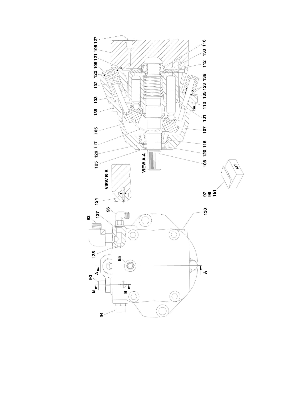
3160291
Ref
DRIVE MOTOR ASSEMBLY
C
101
7012716
1
Rotary Group Assembly
102
See Note
1
Piston, Control (Note: Not Available - Purchase Complete)
103
See Note
1
Rod, Piston (Note: Not Available - Purchase Complete)
105
See Note
1
Housing (Note: Not Available - Purchase Complete)
106
See Note
1
Plate, Port (Note: Not Available - Purchase Complete)
107
7024036
1
Plate, Swash
108
7024037
1
Driveshaft
109
See Note
1
Plug, Screw (Note: Not Available For Purchase)
112
7012704
1
Shim 113
See Note
1
Stop Screw (Note: Not Available For Purchase)
115
7024038
1
Bearing
116
7012706
1
Bearing
117
7024039
2
Shell, Cradle
120
7024034
1
Seal, Shaft
121
7024034
1
O-Ring
122
7024034
1
O-Ring
123
7024034
2
O-Ring
124
7024034
1
Seal
125
7012715
1
V-Ring 127
7024040
4
Screw, Socket Head M12 x 60mm
129
See Note
1
Ring, Stop (Note: Not Available For Purchase)
130
See Note
1
Plug (Note: Not Available For Purchase)
133
See Note
1
Pin, Dowel (Note: Not Available For Purchase)
135
See Note
1
Nut M10 (Note: Not Available For Purchase)
136
See Note
1
Nut, Cap M10 (Note: Not Available For Purchase)
137
7024034
1
Plug 138
7024041
1
Orifice 139
7024034
1
O-Ring
151
7024034
1
Seal Kit (Includes Items 120-124, 137 & 139)
3121172 1250AJP 35
Page 36

SECTION 1 - FRAME
FIGURE 1-8. DRIVE HUB ASSEMBLY - BONFIGLIOLI (SN 0300103907 to Present)
36 1250AJP 3121172
Page 37

SECTION 1 - FRAME
ITEM
PART NUMBER
QTY
DESCRIPTION
REV
Ref
DRIVE HUB ASSEMBLY WITH FITTINGS AND HARDWARE
2780290
Ref
Drive Hub Assembly (SN 0300103907 through 0300130177)
B 1001093243
Ref
Drive Hub Assembly (SN 0300130178 to Present)
D
Ref
Note: For Machines Built S/N 03001039076 to S/N 0300130178,
Original Equipment may have been replaced with Service
Replacement p/n 1001093243. Refer to tag on hub for
identification before ordering parts.
Ref
Note: Various brands used on Machines Built S/N 0300103907
to present. Identify brand before ordering replacement
Ref
Hub, Torque Options:
2780285
1
Hub, Bonfigioli (Use p/n 1001093242) (SN 0300103907
through 0300130177)
1001093242
1
Hub, Bonfiglioli (SN 0300130178 to Present)
1
70000810
10
Bolt M10 x 25mm
2
70000811
1
O-Ring
3 70000812
1
Pin 4
70000813
2
Bolt M8 x 16mm
5 Ref
Cap, Disconnect Options:
5 70000814
1
Cap, Disconnect (SN 0300103907 through 0300130177)
5 70002393
1
Cap, Disconnect (SN 0300130178 to Present)
6 See Note
2
Plug (Note: Not Available For Purchase)
7 70000815
1
Cover Assembly (Includes Items 2-6 & 8)
8 70000816
1
Pad
9 70000817
1
O-Ring
10
70000818
1
Gear, Primary Sun
11
70000819
1
Ring, Neoprene
12
70000819
2
Washer
13
70000819
1
Spring
14
70000819
1
Shaft
16
70000820
1
Reduction Assembly, Primary
17
70000821
1
Gear, Secondary Sun
18
70000822
1
Reduction Assembly, Secondary
19
70000823
5
Snap Ring
20
70000824
5
Gear Assembly, Planetary
21
70000825
5
Spacer
22
70000826
1
Nut
23 Ref
Housing, Hub Options:
23
See Note
1
Housing, Hub (Note: Not Available - Purchase Complete
Assembly) (SN 0300103907 through 0300130177)
23
70002395
1
Housing, Hub (Includes Item 24) (SN 0300130178 to
Present)
24 Ref
Bearing Options:
24
70000827
2
Roller Bearing (SN 0300103907 through 0300130177)
24
70002396
2
Ball Bearing (SN 0300130178 to Present)
25
70000828
1
Spacer
26
70000829
1
Spacer
27
70000830
1
O-Ring
28
70000831
1
Spacer
29
70000832
1
Seal
30
70000833
1
Ring, Sealing
31
See Note
1
Spindle (Note: Not Available - Purchase Complete Assembly)
FIGURE 1-8. DRIVE HUB ASSEMBLY - BONFIGLIOLI (SN 0300103907 to Present)
3121172 1250AJP 37
Page 38

ITEM
PART NUMBER
QTY
DESCRIPTION
REV
32
70000834
4
Disc, Steel
33
70000835
5
Disc, Lined
34
70000836
1
Spacer
35
70000837
1
Shaft, Brake
36
70000838
1
Snap Ring
37
70000839
1
Ring, Backup
38
70000840
1
O-Ring
39
70000841
1
Spacer
40
70000842
1
Ring, Backup
41
70000843
1
O-Ring
42
70000844
1
O-Ring
43
70000845
1
Ring, Backup
44
70000846
1
Piston, Brake
45
70000847
15
Spring
46
70000848
1
Plate, Spring Retainer
47
70000849
1
Snap Ring
48
70000850
1
O-Ring (Use p/n 3790158)
101
0761215
2
Bolt M12 x 35mm
102
2110404
1
Fitting, Adapter
103
2110808
1
Fitting, Adapter
104
2110812
1
Fitting, Adapter
105
2130406
1
Fitting, 90 Degree Adapter
106
2130812
1
Fitting, 90 Degree Adapter
108
5241200
2
Flatwasher M12 Hardened
109
0100011
AR
Compound, Locking
110
3020008
17 oz
Lubricant HD 80W-90 (Not Shown)
151
70000819
1
Brake Shaft Kit (Includes Items 11-14)
SECTION 1 - FRAME
38 1250AJP 3121172
Page 39

Page 40

SECTION 1 - FRAME
FIGURE 1-9. DRIVE HUB ASSEMBLY - REGGIANA RIDUTTORI (SN 0300103907 to Present)
40 1250AJP 3121172
Page 41

SECTION 1 - FRAME
ITEM
PART NUMBER
QTY
DESCRIPTION
REV
1001104325
Ref
DRIVE HUB ASSEMBLY WITH FITTINGS AND HARDWARE
D
Ref
Note: Various brands used on Machines Built S/N 0300103907
to Present. Identify brand before ordering replacement
parts.parts.
1001101550
1
Hub, Torque
C 1 70002015
8
Bolt M8 x 25mm
2 70002016
1
Ring, Motor Support
3 70002248
1
O-Ring
4 70002018
1
Snap Ring
5 70002019
1
Retainer, Spring
6 70002020
9
Spring 7
70002021
1
Piston 8
See Note
1
Ring, Backup (Note: Use Item 51 or 53.)
9 See Note
1
O-Ring (Note: Use Item 51 or 53.)
10
See Note
1
O-Ring (Note: Use Item 51 or 53.)
11
See Note
1
Ring, Backup (Note: Use Item 51 or 53.)
12
70002026
5
Disc, Friction
13
70002027
6
Disc, Steel
15
70002029
1
Spindle
16
70002030
4
Gear, Planetary
17
70002031
4
Bearing
18
70002032
5
Snap Ring
19
70002033
1
Gear, Brake/Input
20
70002034
1
Bearing
22
70002035
1
Ring, Wear
23
70002036
1
Spring
24
70002037
1
Shaft, Engagement
25
70002248
1
Seal 26
70002039
2
Bearing Assembly
27
70002040
1
Support, Hub
28
70002041
1
Nut, Retaining
29
70002674
4
Washer (was p/n70002042)
30
70002674
4
Screw (was p/n 70002043)
31
70002044
1
Gear, Planetary Sun
32
70002045
1
Reduction Assembly, Secondary
33
70002046
1
Snap Ring
34
70002047
1
Gear, Secondary Input Sun
35
70002048
1
Reduction Assembly, Primary
36
70002049
1
Snap Ring
37
70002050
1
Gear, Primary Input Sun
38
70002248
1
O-Ring
39
See Note
1
Housing, Hub (Note: Not Available - Purchase Complete
Assembly)
40
70002052
2
Screw, Countersunk
41
See Note
1
O-Ring (Note: Use Item 51 or 52.)
42
70002247
1
Thrustwasher
43
See Note
1
O-Ring (Note: Use Item 51 or 52.)
44
70002247
1
Cover, Hub
45
70002057
3
Plug 46
70002247
1
Snap Ring
FIGURE 1-9. DRIVE HUB ASSEMBLY - REGGIANA RIDUTTORI (SN 0300103907 to Present)
3121172 1250AJP 41
Page 42

ITEM
PART NUMBER
QTY
DESCRIPTION
REV
47
70002247
1
Pin, Engagement
48
See Note
1
Gasket (Note: Use Item 51 or 52.)
49
70002247
1
Cover, Engagement
50
70002247
2
Screw 51
70002248
1
Seal Kit (Includes Items 3, 8-11, 25, 38, 41, 43 & 48)
52
70002247
1
Cover Kit (Includes Items 41-50)
53
70002249
1
Brake Kit (Includes Items 4-13)
101
0761214
2
Bolt M12 x 30mm
102
2110404
1
Fitting, Adapter
103
2110808
1
Fitting, Adapter
104
2110812
1
Fitting, Adapter
105
2130406
1
Fitting, 90 Degree Adapter
106
2130812
1
Fitting, 90 Degree Adapter
108
5241200
2
Flatwasher M12 Hardened
109
0100011
AR
Compound, Locking
110
3790158
1
O-Ring
111
3020008
17 oz
Lubricant HD 80W-90 (Not Shown)
SECTION 1 - FRAME
42 1250AJP 3121172
Page 43

Page 44

SECTION 1 - FRAME
FIGURE 1-10. DRIVE MOTOR ASSEMBLY (SN 0300103907 to Present)
44 1250AJP 3121172
Page 45

SECTION 1 - FRAME
ITEM
PART NUMBER
QTY
DESCRIPTION
REV
3160339
Ref
DRIVE MOTOR ASSEMBLY
B 1 7022368
4
Bolt 2
70000859
1
End Cap, Motor
3 70003628
2
Locating Pin
4 70000862
1
O-Ring 5
7007420
1
Plug (Includes Item 4)
6 7007446
1
Pin, Dowel
7 7021249
1
Bearing, Needle
8 70000854
1
Plate, Valve
9 7022311
1
Snap Ring
10
7022314
1
Retainer, Spring
11
7024867
1
Spring 12
7024868
1
Washer (was p/n 7022313)
13
70000855
1
Block, Cylinder
14
7021275
3
Pin, Slipper
15
70000856
1
Guide 16
70000857
1
Retainer, Slipper
17
7024865
9
Piston, Cylinder
18
70000862
1
Ring, Piston
19
70000862
1
O-Ring 20
70000860
1
Piston, Servo (Includes Items 18 & 19)
21
70000861
1
Spring 22
See Note
1
Pin (Note: Not Available for Purchase)
23
70000853
1
Swashplate
24
70000852
1
Bearing Kit
25
70000862
1
Gasket
26
See Note
1
Plug (Note: Not Available for Purchase)
27
70000862
1
O-Ring 28
7022321
1
Plug (Includes Item 29)
29
70000862
1
O-Ring 30
See Note
1
Housing (Note: Not Available - Purchase Complete Motor)
31
70000858
1
Shaft 32
7007437
1
Bearing
33
7007439
1
Snap Ring
34
7007438
2
Snap Ring
35
70000862
1
Seal 36
7022371
1
Washer, Seal Support
51
70000862
1
Kit 1 - Motor Seal Kit (Includes Items 4, 18, 19, 25, 27, 29 & 35)
52
7027740
1
Kit 2 - Cylinder Block Kit (Includes Items 9 - 17)
FIGURE 1-10. DRIVE MOTOR ASSEMBLY (SN 0300103907 to Present)
3121172 1250AJP 45
Page 46

SECTION 1 - FRAME
FIGURE 1-11. FRAME VALVES AND COVERS INSTALLATION
46 1250AJP 3121172
Page 47

SECTION 1 - FRAME
ITEM
PART NUMBER
QTY
DESCRIPTION
REV
0273377
Ref
FRAME VALVES INSTALLATION
L 1 0100011
AR
Compound, Locking
6 0641424
2
Bolt 1/4in-20NC x 3in
7 0641504
8
Bolt 5/16in-18NC x 1/2in
8 0641509
4
Bolt 5/16in-18NC x1-1/8in
9 0641608
12
Bolt 3/8in-16NC x 1in
10
0641808
4
Bolt 1/2in-13NC x 1in
13
1600331
1
Module (Chassis) (Note: Control System must be recalibrated
when Module is replaced) (Use p/n 1001112758) (Prior to
0300141570)
13
2915024
1
Update Kit (Includes Cables, Programming Instructions and CD
Software)
16
3311405
2
Locknut 1/4in-20NC
17
3311505
4
Locknut 5/16in-18NC
18
3311605
4
Locknut 3/8in16NC
19
3841340
2
Loop, Hose
22
4060808
124
in/3.2m
Flex-Trim
23
4641155
1
Manifold, Junction
25
4641268
2
Valve Assembly - Steer
B
25A
7026028
12
Cartridge (6 Per Valve)
25A
7011346
12
Seal Kit - Cartridge (1 Per Cartridge)
25B
7024927
4
Valve (2 Per Valve)
25B
7012773
4
Seal Kit - Cartridge (1 Per Cartridge)
25B
7018991
8
Coil (2 Per Valve)
25C
70001976
2
Valve (1 Per Valve) (was p/n 7012770)
25C
7012773
2
Seal Kit - Cartridge (1 Per Cartridge)
25C
7018991
4
Coil (2 Per Valve)
25C
70001939
2
Orifice
25D
2221086
6
Check, Pressure
25E
2110606
8
Fitting, Straight
25F
2130810
2
Fitting, 90 Degree
26 Ref
Traction Valve Assembly Options:
26
4641269
1
Traction Valve Assembly (See TRACTION VALVE ASSEMBLY
for Breakdown) (Prior to SN 0300103907)
26
4641454
1
Traction Valve Assembly (See TRACTION VALVE ASSEMBLY
for Breakdown) (SN 0300103907 to Present)
28
4711400
8
Flatwasher 1/4in Thin
29
4711500
16
Flatwasher 5/16in Thin
30
4711600
8
Flatwasher 3/8in Thin
31
4711800
4
Flatwasher 1/2in Thin
Ref
FRAME COVERS INSTALLATION
0271523
Ref
Frame Covers Installation (Prior to SN 0300195073)
C 1001176346
Ref
Frame Covers Installation (SN 0300195073 to Present)
C
101
0100011
AR
Compound, Locking
102
0791604
AR
Screw 3/8in-16NC x 1/2in
103
0791607
16
Screw 3/8in-16NC x 7/8in
104
1670996
1
Cover, Front
105
1671045
4
Plate, Cover (Axle Side)
106
1671046
4
Plate, Cover (Axle Corner)
107
1671047
1
Plate, Cover (Rear)
FIGURE 1-11. FRAME VALVES AND COVERS INSTALLATION
3121172 1250AJP 47
Page 48

ITEM
PART NUMBER
QTY
DESCRIPTION
REV
108
1671048
2
Plate, Cover (Frame Top)
109
1671049
4
Plate, Cover (Frame Side)
110
3900283
AR
Screw, Button Head 3/8in-16NC x 3/4in
111
4751600
AR
Flatwasher 3/8in Regular
112
0791410
20
Screw, 1/4in-20NC x 1 1/4in (SN 0300195073 to Present)
113
8580420
40
Nut, well (SN 0300195073 to Present)
114
0641410
16
Bolt, 1/4in-20NC x 1 1/4in (SN 0300195073 to Present)
115
4751400
16
Flatwasher 1/8in Regular (SN 0300195073 to Present)
116
0641412
4
Bolt, 1/4in-20NC x 1 1/2in (SN 0300195073 to Present)
117
4740430
4
Flatwasher, Fender (SN 0300195073 to Present)
SECTION 1 - FRAME
48 1250AJP 3121172
Page 49

Page 50

SECTION 1 - FRAME
FIGURE 1-12. TRACTION VALVE ASSEMBLY (Prior to SN 0300103907)
50 1250AJP 3121172
Page 51

SECTION 1 - FRAME
ITEM
PART NUMBER
QTY
DESCRIPTION
REV
4641269
Ref
TRACTION VALVE ASSEMBLY
C 2 7026025
2
Cartridge, Valve (Flow Divider)
2 70002519
2
Seal Kit - 7026025 Cartridge
3 7026026
1
Cartridge, Valve (Shuttle)
3 70002519
1
Seal Kit - 7026026 Cartridge
4 7026027
1
Cartridge, Valve (Relief)
4 7011346
1
Seal Kit - 7026027 Cartridge
5 7018900
2
Orifice 1.2mm
6 7024570
3
Cartridge, Valve (Steer, Brake and Lockout)
6 70001930
3
Seal Kit - 7024570 Cartridge
6A
7024571
3
Coil 7
7011355
3
Cartridge, Valve (Shuttle)
7 2900770
3
Seal Kit - 7011355 Cartridge
8 7026012
4
Cartridge, Valve (Check)
8 7011346
4
Seal Kit - 7026012 Cartridge
11
2111012
2
Fitting, Straight
12
2151012
2
Fitting, 45 Degree
13
2110810
9
Fitting, Straight
14
2110406
1
Fitting, Straight
15
2180831
1
Fitting, Orifice
16
2221086
1
Check, Pressure
17
2220883
1
Fitting, Plug
18
7024932
1
Switch, Pressure
FIGURE 1-12. TRACTION VALVE ASSEMBLY (Prior to SN 0300103907)
3121172 1250AJP 51
Page 52

SECTION 1 - FRAME
FIGURE 1-13. TRACTION VALVE ASSEMBLY (SN 0300103907 to Present)
52 1250AJP 3121172
Page 53

SECTION 1 - FRAME
ITEM
PART NUMBER
QTY
DESCRIPTION
REV
4641454
Ref
TRACTION VALVE ASSEMBLY
E 1 7012941
3
Cartridge, Valve (Steer, Brake and Axle Lockout)
1 7010543
3
Seal Kit - 7012941 Cartridge
1A
7012944
2
Coil 2
70000801
1
Cartridge, Valve (Relief)
2 7012998
1
Seal Kit - 70000801 Cartridge
3 70000802
1
Cartridge, Valve (Pilot)
3 7012942
1
Seal Kit - 70000802 Cartridge
4 70000803
1
Pressure Switch
5 70000804
1
Cartridge, Valve (Shuttle)
5 70000805
1
Seal Kit - 70000804 Cartridge
6 70000806
2
Cartridge, Valve (Flow Divider)
6 7017405
2
Seal Kit - 70000806 Cartridge
7 7012955
4
Cartridge, Valve (Check)
7 7012967
4
Seal Kit - 7012955 Cartridge
8 2111012
2
Fitting, Straight
9 2151012
2
Fitting, 45 Degree
10
2110810
13
Fitting, Straight
11
2110406
3
Fitting, Straight
12
2221086
1
Check, Pressure
13
2220883
1
Plug, #4 (Not Shown)
FIGURE 1-13. TRACTION VALVE ASSEMBLY (SN 0300103907 to Present)
3121172 1250AJP 53
Page 54

Page 55

SECTION 2 - TURNTABLE
SECTION 2 - TURNTABLE
3121172 1250AJP 55
Page 56

SECTION 2 - TURNTABLE
FIGURE 2-1. VALVE, BATTERY, HORN AND AUXILIARY PUMP INSTALLATIONS
56 1250AJP 3121172
Page 57

SECTION 2 - TURNTABLE
3121172 1250AJP 57
Page 58

ITEM
PART NUMBER
QTY
DESCRIPTION
REV
0273377
Ref
VALVES INSTALLATION - TURNTABLE MOUNTED
L 1 0100011
AR
Compound, Locking
2 0140001
1
Horn 3
0641406
5
Bolt 1/4in-20NC x 3/4in
5 0641408
2
Bolt 1/4in-20NC x 1in
9 0641608
8
Bolt 3/8in-16NC x 1in
11
0902800
1
Bracket, Module Mounting
12
1320322
1
Clamp
14
1600332
1
Module, B.L.A.M. (1 Control System must be recalibrated when
Module is replaced) (Use p/n 1001112757) (Prior to SN
0300141570)
14
2915024
1
Update Kit (Includes Cables, Programming Instructions and CD
Software)
15
3300454
4
Nut, Special
27 Ref
Main Valve Assembly Options (See MAIN VALVE ASSEMBLY for
Breakdown):
27
4641304
1
Valve, Main Control (Use p/n 1001103793) (Prior to SN
0300119708)
27
1001103793
1
Valve, Main Control (SN 0300128768 to Present)
28
4711400
5
Flatwasher 1/4in Thin
30
4711600
12
Flatwasher 3/8inThin
32
4791400
1
Starwasher 1/4in
34
0641620
2
Bolt 3/8in-16NC x 2 1/2in
35
0641636
2
Bolt 3/8in-16NC x 4 1/2in
36
3380523
1
Shield, Tube
37 Ref
Enable Valve Assembly Options:
37
See Note
3
Valve Assembly (was p/n 4641306, 4641381 & 4641391) (Prior
to SN 0300131893)
Ref
NOTE: The above listed enable valves and any associated
service parts are no longer available for service. Verify
stamping on valve block. If valve is JLG P/N 4641306 (valve
block stamped with P/N CP12673), JLG P/N 4641381 (valve
block stamped with P/N HA1022) or JLG P/N 4641391 (valve
block stamped with P/N HA60220) you must replace all 3
enable valves with JLG P/N 1001106391.
Ref
If your machine is already equipped with JLG P/N
1001106391 (valve block stamped with P/N HF46525-08)
valves can then be replaced on an as required basis.
37
1001106391
3
Valve, Solenoid (Use p/n 1001112850) (SN 0300131893 to
Present)
37
7024890
1
Coil
Ref
BATTERY AND AUXILIARY PUMP INSTALLATION (WITHOUT
COLD WEATHER PLUS PACKAGE)
0273418
Ref
Battery and Auxiliary Pump Installation (Prior to SN
0300167530)
E 1001145323
Ref
Battery and Auxiliary Pump Installation (SN 0300167530 to
Present)
B
101
0100011
AR
Compound, Locking
102
0236768
4
Rod, Hold-down
103
0363062
2
Bar, Battery
104
0400020
1
Battery
105
0641404
2
Bolt 1/4in-20NC x 1/2in
106
0641607
AR
Bolt 3/8in-16NC x 7/8in
SECTION 2 - TURNTABLE
FIGURE 2-1. VALVE, BATTERY, HORN AND AUXILIARY PUMP INSTALLATIONS
58 1250AJP 3121172
Page 59

SECTION 2 - TURNTABLE
ITEM
PART NUMBER
QTY
DESCRIPTION
REV
107
Ref
Bracket Options:
107
0902916
1
Bracket (Use with Auxiliary Pump p/n 3600342) (Prior to SN
0300103853)
107
0903696
1
Bracket (Use with Auxiliary Pump p/n 3600465) (SN 0300103853
to Present)
108
3311608
4
Nut, Flange 3/8in-16NC
109
See Note
1
Auxiliary Pump Assembly Options:
Ref
Note: Various pumps were used in production.
Ref
Note: For Machines Built Prior to S/N 0300103853, Purchase
Bracket p/n 0903696 and Service Kit p/n 1001164700 as
Service Replacement.
Ref
Note: For Machines Built S/N 0300103853 to S/N 0300179652,
Use Kit p/n 1001164700 as Service Replacement.
Ref
Note: For replacement parts for existing pump assemblies
see below:
109
See Note
Ref
3600342 Assembly (Fenner Fluid Power/SPX Brand) (See
Items 201-205 for Serviced Parts)
109
See Note
1
3600465 Assembly (Haldex Brand) (See Items 301-305 for
Serviced Parts)
109
See Note
1
1001137442 Assembly (Bucher Brand with 3.02cc Pump) (See
Items 401-408 for Serviced Parts)
109
See Note
1
1001162880 Assembly (Bucher Brand with 3.50cc Pump) (See
Items 501-508 for Serviced Parts)
111
3980006
1
Seat, battery
112
4420037
17
in/43cm
Tape, Insulation
113
4711400
2
Flatwasher 1/4in Thin
114
4711600
AR
Flatwasher 3/8in Thin
115
4751600
4
Flatwasher 3/8in Regular
116
4791400
2
Starwasher 1/4in
Ref
3600342 AUXILIARY PUMP ASSEMBLY (FENNER FLUID
POWER/SPX BRAND) REPLACEMENT PARTS
201
7022207
Motor 201
7013753
1
Brush Kit
202
7016769
1
Bracket, Motor/Pump
202
Not Required
0
Not Required
202
7013711
1
Coupling
203
7022215
Pump
203
7013716
1
Seal, Shaft
204
7013715
1
Ball 204
7022227
1
Spring 204
7022228
1
Screw, Valve Adjustment
204
7022230
1
Cap, Relief Valve
205
7022231
1
Ball and Spring Assembly
205
7022229
1
Plug Ref
3600465 AUXILIARY PUMP ASSEMBLY (HALDEX BRAND)
301
7010924
Motor 301
7010639
2
Brush
301
7010640
8
Spring, Brush
302
70000998
1
Coupling
303
70001001
Pump 303
70001000
1
Seal Kit
304
See Note
1
Ball (Note: Not Available for Purchase)
See Note
1
Spring (Note: Not Available for Purchase)
3121172 1250AJP 59
Page 60

ITEM
PART NUMBER
QTY
DESCRIPTION
REV
See Note
1
Screw, Valve Adjustment (Note: Not Available for Purchase)
See Note
1
Cap, Relief Valve (Note: Not Available for Purchase)
305
See Note
1
Ball and Spring Assembly (Note: Not Available for Purchase)
See Note
1
Plug (Note: Not Available for Purchase)
Ref
1001137442 AUXILIARY PUMP ASSEMBLY (BUCHER BRAND
WITH 3.02CC PUMP)
401
1001164700
1
Base Assembly
401
7026330
1
Seal, Shaft
402
70004002
1
Pump 403
1001164700
1
Valve, Relief
404
70007003
1
Motor 405
70007004
4
Screw Metric M5 x 65mm
406
70007005
4
Screw 1/4in - 20NC x 3in
407
70007006
1
Nut 3/8in - 16NC
408
70007007
1
Screw 3/8in - 16NC x 3/4in
Ref
1001162880 AUXILIARY PUMP ASSEMBLY (BUCHER BRAND
WITH 3.50CC PUMP)
501
1001164700
1
Base Assembly
502
1001164700
1
Valve, Relief
503
See Note
1
Motor (Note: Not Available for Purchase)
504
70007006
1
Nut 3/8in - 16NC
505
70007007
1
Screw 3/8in - 16NC x 3/4in
506
70007005
4
Screw 1/4in - 20NC x 3in
506
See Note
1
Sleeve (Note: Not Available for Purchase)
507
See Note
1
Pump Assembly (Note: Not Available for Purchase)
See Note
1
Seal, Shaft (Note: Not Available for Purchase)
508
See Note
4
Screw M8 x 85mm (Note: Not Available for Purchase)
Ref
BATTERY AND AUXILIARY PUMP INSTALLATIONS (WITH
COLD WEATHER PLUS PACKAGE)
1001133463
Ref
Battery and Auxiliary Pump Installation (Prior to SN
0300158094)
A
1001139520
Ref
Battery and Auxiliary Pump Installation (SN 0300158094 to
Present)
A
601
0100011
AR
Compound, Locking
602
0236768
4
Rod, Hold-down
603
0363062
2
Bar, Battery
604
0400020
1
Battery
605
0641404
2
Bolt 1/4in-20NC x 1/2in
606
0641413
2
Bolt 1/4in-20NC x 1-5/8in
607
0641607
4
Bolt 3/8in-16NC x 7/8in
616
3311608
4
Nut, Flange 3/8in-16NC
617
3740067
1
Relay
618
3980006
1
Seat, battery
619
4420037
17
in/43cm
Tape, Insulation
621
4711400
4
Flatwasher 1/4in Thin
622
4711600
4
Flatwasher 3/8in Thin
623
4751600
4
Flatwasher 3/8in Regular
624
4791400
2
Starwasher 1/4in
626
0903696
1
Bracket
627
Ref
Auxiliary Pump Assemblies
627
1001133162
1
Auxiliary Pump Assembly (Use p/n 1001139878 - No Service
Parts Available) (Prior to SN 0300158094)
SECTION 2 - TURNTABLE
60 1250AJP 3121172
Page 61

SECTION 2 - TURNTABLE
ITEM
PART NUMBER
QTY
DESCRIPTION
REV
627
1001138838
1
Auxiliary Pump Assembly (SN 0300158094 to Present)
627
70003800
1
Motor (p/n 1001138838 Assembly)
627
70003803
1
Pump Assembly (p/n 1001138838 Assembly)
627
70003801
4
Capscrew 5/16in-18NC x 3/4in (Pump Mounting)
627
70003802
4
Lockwasher 5/16in
628
1001133163
1
Valve, Relief
628
7023936
1
Seal Kit
629
1001133593
1
Bracket
630
4761600
4
Lockwasher 3/8in
631
3311601
2
Nut 3/8in-16NC
3121172 1250AJP 61
Page 62

SECTION 2 - TURNTABLE
FIGURE 2-2. MAIN VALVE ASSEMBLY
62 1250AJP 3121172
Page 63

SECTION 2 - TURNTABLE
ITEM
PART NUMBER
QTY
DESCRIPTION
REV
Ref
MAIN VALVE ASSEMBLY
4641304
Ref
Main Valve Assembly (Use p/n 1001103793) (Prior to SN
0300119708)
E
1001099515
Ref
Main Valve Assembly (Use p/n 1001103793) (SN 0300119708
through 0300128767)
B
1001103793
Ref
Main Valve Assembly (SN 0300128768 to Present)
C
Ref
MAIN VALVE BODY COMPONENTS
1 7026684
4
Cartridge, Check Valve
1 7026685
4
Seal Kit - Valve
2 7026686
2
Cartridge, Relief Valve
2 7026687
2
Seal Kit - Valve
3 7026688
1
Cartridge, Check Valve
3 7026689
1
Seal Kit - Valve
4 7026690
3
Cartridge, Solenoid Valve Less Coil
4 7026691
3
Seal Kit - Valve
4 7027206
3
Coil 5
7026692
2
Cartridge, Solenoid Valve Less Coil
5 7026693
2
Seal Kit - Valve
5 7027207
2
Coil 6
7026694
1
Cartridge, Differential Sensing Valve
6 7026695
1
Seal Kit - Valve
7 7026696
1
Cartridge, Differential Sensing Valve
7 7026697
1
Seal Kit - Valve
8 7026698
1
Cartridge, Solenoid Valve Less Coil
8 See Note
1
Seal Kit - Valve (Note: Not Available for Purchase)
8 7027209
2
Coil 9
7027882
1
Valve Assembly, Solenoid (was p/n 7026699)
9 7026693
1
Seal Kit - Valve
9 7027208
1
Coil 10
7027200
2
Cartridge, Solenoid Valve
10
7010697
2
Seal Kit - Valve
10
7012943
2
Coil 12
7027201
1
Cartridge, Check Valve
12
7027202
1
Seal Kit - Valve
13
7027203
1
Cartridge, Check Valve
13
7026687
1
Seal Kit - Valve
30
7027738
1
Switch, Thermostatic
31
3930608
2
Screw, Countersunk #6-32NC x 1/2in
32
7027204
2
Cartridge, Relief Valve
32
7026687
2
Seal Kit - Valve
33
1001104841
2
Lock Plate, Cartridge
33
3941404
2
Screw, Self-Tapping
Ref
MAIN VALVE BODY FITTINGS
101
2111210
1
Fitting, Straight
102
2111010
2
Fitting, Straight
103
2110606
5
Fitting, Straight
104
2110406
2
Fitting, Straight
105
2110404
2
Fitting, Straight
106
2221086
5
Check, Pressure
107
2112016
1
Fitting, Straight
FIGURE 2-2. MAIN VALVE ASSEMBLY
3121172 1250AJP 63
Page 64

ITEM
PART NUMBER
QTY
DESCRIPTION
REV
108
2111216
1
Fitting, Straight
109
2111212
1
Fitting, Straight
110
2220887
1
Plug
Ref
PROPORTIONAL VALVE SECTION AND ADDITIONAL
COMPONENTS
201
7026671
2
Bracket
203
Item 212
1
Spool Assembly (Tower Telescope) (was p/n 7026681)
204
Item 212
2
Spool Assembly (Tower/Main Lift) (was p/n 7026682)
205
7026672
1
Switch, Pressure
206
Item 212
2
Valve, Shock (was p/n 7026673)
207
Item 212
4
Valve, Shock (was p/n 7026674)
208
Item 212
3
Cover (was p/n 7026675)
208
8007894
AR
Seal Kit, Cover Mounting (1 per cover)
209
Ref
Actuator, Electrical Options:
209
70001873
3
Actuator, Electrical (was p/n 7026676) (Prior to SN
0300119708)
209
70001873
3
Actuator, Electrical (SN 0300128768 to Present)
209
70001873
3
Actuator, Electrical (was p/n 70001420) (SN 0300119708
through 0300128767)
209
8007954
AR
Seal Kit, Actuator Mounting (1 per actuator)
210
Ref
Module, Pump Side Options:
210
70001421
1
Module, Pump Side (was p/n 7026677) (Prior to SN
0300119708)
210
70001421
1
Module, Pump Side (SN 0300119708 to Present)
210
8007939
1
Seal Kit, Pump Side Module (Internal Seals for Pump Side
Module)
211
7026678
1
Plug with Check Valve
212
70002742
1
Module, Tower Lift (Includes Items 204, 207, 208, 210 Seal Kit
and p/n 8007935 Seal Kit) (was p/n 7026679)
212
70002743
1
Module, Tower Telescope (Includes Items 203, 206, 208, 210
Seal Kit and p/n 8007935 Seal Kit) (was p/n 7026679)
212
70003043
1
Module, Main Lift (Includes Items 204, 207, 208, 210 Seal Kit and
p/n 8007935 Seal Kit) (was p/n 7026679)
212
8007935
AR
Seal Kit, Module Mounting (includes seals for one side of
Module - requires four for complete valve)
213
7026680
1
Tie-Rod Kit (Includes Hardware and Seals)
214
See Note
1
Fitting, Adapter (Note: Not Available for Purchase)
Ref
PROPORTIONAL VALVE SECTION FITTINGS
301
2111210
1
Fitting, Straight
302
2111010
1
Fitting, Straight
303
2131010
1
Fitting, 90 Degree
304
2110810
1
Fitting, Straight
305
2130810
1
Fitting, 90 Degree
306
2111210
1
Fitting, Straight
307
7026683
2
Fitting, Straight
308
2221086
1
Check, Pressure
309
2110404
1
Fitting, Straight
310
2220888
1
Plug
SECTION 2 - TURNTABLE
64 1250AJP 3121172
Page 65

Page 66

SECTION 2 - TURNTABLE
FIGURE 2-3. TURNTABLE SWING DRIVE AND BEARING INSTALLATION
66 1250AJP 3121172
Page 67

SECTION 2 - TURNTABLE
ITEM
PART NUMBER
QTY
DESCRIPTION
REV
0271596
Ref
SWING DRIVE INSTALLATION
D 1 0100019
AR
Compound, Locking
2 0682418
5
Bolt 7/8in-9NC x 2-1/4in (Grade 8)
3 Ref
Swing Motor/Hub Assembly (See SWING MOTOR/HUB
ASSEMBLY for Breakdown)
3
3160302
1
Hub, Swing Drive (Use p/n 1001134098) (Prior to SN
0300151926)
3
1001134098
1
Hub, Swing Drive (SN 0300151926 to Present)
4 3312002
1
Nut, Jam 5/8in-11NC
5 3900223
1
Screw, Shoulder
6 3952020
1
Setscrew 5/8in-11NC x 2-1/2in
7 4071041
1
Shim 8
4892400
5
Flatwasher 7/8in Hardened
0273451
Ref
TURNTABLE BEARING AND LUBE INSTALLATION
B
101
0100019
AR
Compound, Locking
102
0440251
1
Bearing, Turntable
103
0682026
40
Bolt 5/8in-11NC x 3-1/4in (Grade 8)
104
0682040
40
Bolt 5/8in-11NC x 5in (Grade 8)
105
2180002
2
Fitting, Grease
106
2180344
2
Fitting, Bulkhead
107
2220001
2
Fitting, Straight Swivel
109
2750528
2
Hose 110
4892000
80
Flatwasher 5/8in Hardened
0239842
Ref
TURNTABLE LOCK INSTALLATION
B
202
3421565
1
Pin, Snap
203
1260017
9 in/23cm
Chain - #3
204
3760170
2
Ring, Quick Release
205
3421563
1
Pin, Turntable Lock
0271874
Ref
PINION SHIELD INSTALLATION
A
301
0100011
AR
Compound, Locking
302
0641608
4
Bolt 3/8in-16NC x 1in
303
3573355
1
Shield 304
4751600
4
Flatwasher 3/8in Regular
FIGURE 2-3. TURNTABLE SWING DRIVE AND BEARING INSTALLATION
3121172 1250AJP 67
Page 68

SECTION 2 - TURNTABLE
FIGURE 2-4. SWING MOTOR/HUB ASSEMBLY
68 1250AJP 3121172
Page 69

SECTION 2 - TURNTABLE
3121172 1250AJP 69
Page 70

ITEM
PART NUMBER
QTY
DESCRIPTION
REV
Ref
SWING MOTOR/HUB ASSEMBLIES
3160302
Ref
Swing Motor/Hub Assembly (Prior to SN 0300151926)
B 1001134098
Ref
Swing Motor/Hub Assembly (SN 0300151926 to Present)
C
Ref
Note: Original Equipment p/n 3160302 may have been
replaced with Service Replacement p/n 1001134098, identify
component by brand before ordering parts.
1
See Note
1
Housing/Shaft Assembly (Note: Not Available - Purchase
1A
7024183
1
Shaft, Out put
1B
7000236
1
Seal, Lip
1C
1001091460
1
Cup, Bearing (was p/n 7000272 & p/n 90202500)
1D
1001091460
1
Cone, Bearing (was p/n 7000273 & p/n 90202501)
1E
1001091461
1
Cup, Bearing (was p/n 7000274)
1F
1001091461
1
Cone, Bearing (was p/n 7000275 & p/n 90202503)
1G
7024184
1
Housing
1H
7000239
1
Thrustwasher
1I
7000240
1
Ring, Retaining
1J
7017072
1
Plug, Pipe
2 7001917
1
Gear, Internal
3 7001918
1
Carrier Assembly
3A
7001900
1
Carrier
3B
7007645
6
Washer, Tanged
3C
7001902
84
Bearing, Needle
3D
7007646
3
Thrustwasher
3E
7001904
3
Shaft, Planet
3F
7001927
3
Gear, Cluster
3G
7001906
3
Rollpin
3H
7007648
6
Washer
4 7010467
1
Gear, Ring
5 7000224
2
O-Ring
6 7001920
1
Cover, Input
8 7001922
1
Thrustwasher
10
7024188
1
Motor Assembly (See Items 101-121 for Breakdown)
13
7001921
1
Gear, Sun
15
7000287
4
Thrustwasher
16
7000288
2
Bearing, Thrust
17
7001923
8
Bolt 3/8in-16NC x 3in (Grade 8)
18
7001924
4
Bolt Shoulder 3/8in-16NC x 2-3/4in (Grade 8)
19
7001929
4
Lockwasher (Used with Item 18 Only)
20 Ref
Plug, Pipe Options:
20
7001928
1
Used With Swing Motor/Hub Assembly p/n 3160302
20
7017094
1
Used With Swing Motor/Hub Assembly p/n 1001134098
21
7001926
2
Plug, Pipe
22
7017082
1
Plug, Pipe
24
See Note
1
Plate, ID (Note: Not Available for Purchase)
25
7000281
2
Screw, Drive
26 Ref
Brake Assembly Options (See Items 201-223 for Breakdown):
26
7024182
1
Brake Assembly (Prior to SN 0300151926)
26
70003524
1
Brake Assembly (SN 0300151926 to Present)
27
7024763
1
O-Ring
28
See Note
2
Lug, Lifting (Note: Not Available for Purchase)
SECTION 2 - TURNTABLE
FIGURE 2-4. SWING MOTOR/HUB ASSEMBLY
70 1250AJP 3121172
Page 71

SECTION 2 - TURNTABLE
ITEM
PART NUMBER
QTY
DESCRIPTION
REV
29
7024185
2
Bolt 1/2in-13NC x 5in (Grade 8)
31
7000731
1
Gasket
32 Ref
Valve Options:
32 Ref
Used With Swing Motor/Hub Assembly p/n 3160302
32
4640741
1
Valve (was p/n 7024187)
32
7011320
2
Cartridge
32
2900770
2
Seal Kit - 7011320 Cartridge (1 Per Cartridge)
32 Ref
Used With Swing Motor/Hub Assembly p/n 1001134098
32
70003523
1
Valve
32
70003629
2
Cartridge
33
See Note
4
Lockwasher (Note: Not Available - Purchase Locally)
34
7024135
4
Bolt 5/16in-18NC x 2-1/2in (Grade 8)
35
7024186
1
Tube 36
7017085
2
Elbow
37
7000213
2
O-Ring
7024188
Ref
MOTOR ASSEMBLY
101
7024391
5
Bolt 102
7004035
1
Cover, End
103
Item 126
1
Seal, Commutator
104
Item 126
5
Seal, Ring
105
7024453
1
Commutator and Ring Assembly (was p/n 7004037)
106
7004453
1
Ring 107
7024379
Manifold
108
7024392
1
Rotor Set
109
7024380
1
Plate, Wear
110
7024393
1
Link, Drive
112
7024395
1
Shaft, Coupling
113
7024381
1
Bushing, Bronze
114
7004043
1
Thrustwasher
115
7004044
1
Bearing, Thrust
116
Item 126
Seal, Inner
117
Item 126
1
Washer, Back-up
118
7024394
1
Housing
119
7024390
1
Bearing
120
Item 126
1
Seal 121
7010795
1
Plug, O-Ring
126
7024389
1
Seal Kit - 7024188 Motor (Includes Items 103, 104, 116, 117 &
120) (was p/n 7024396)
Ref
BRAKE ASSEMBLIES
7024182
Ref
Brake Assembly (Prior to SN 0300151926)
70003524
Ref
Brake Assembly (SN 0300151926 to Present)
201
7024189
1
Shaft 202
See Note
1
Housing (Note: Not Available - Purchase Complete Assembly)
203
Item 227
2
Plate, Friction
204
Item 227
1
Plate, Pressure
205
7000731
1
Gasket
206
Item 227
2
Plate, Outer
207
See Note
1
Gasket (Note: Use Item 226 or 227)
208
7024191
1
Cylinder
209
7024192
1
Piston
210
Item 227
1
Bearing, Ball
211
Item 227
1
Ring, Retaining
3121172 1250AJP 71
Page 72

ITEM
PART NUMBER
QTY
DESCRIPTION
REV
212
Item 227
1
Seal, Shaft
213
See Note
6
Capscrew (Note: Not Available - Purchase Locally)
214
See Note
6
Lockwasher (Note: Not Available - Purchase Locally)
215
Item 226
1
O-Ring
216
Item 226
1
Ring, Back-up
217
Item 226
1
O-Ring
218
Item 226
1
Ring, Back-up
219
7024190
2
Pin, Dowel
220
See Note
1
Plug (Note: Not Available - Purchase Locally)
221
See Note
1
Plug (Note: Not Available - Purchase Locally)
222
Item 227
AR
Spring (Natural)
223
Item 227
AR
Spring, (Blue)
226
7024194
1
Seal Kit - Brake (Includes Items 205, 207 & 215-218)
227
7024196
NLA
Spring Kit - Brake (Includes 12 Natural Colored Springs) (was p/n
7024195) Note: Spring Kit p/n 7024195 no Longer Available,
Purchase p/n 7024196 for Replacement.
7024196
1
Spring Kit - Brake (Includes 12 Natural and 2 Blue Colored
Springs)
7024193
1
Friction Disc Kit - Brake (Includes Items 203, 204, 206 & 207)
7024197
1
Bearing Kit - Brake (Includes Items 207 & 210-212)
SECTION 2 - TURNTABLE
72 1250AJP 3121172
Page 73

Page 74

SECTION 2 - TURNTABLE
FIGURE 2-5. CATERPILLAR DIESEL ENGINE INSTALLATION
74 1250AJP 3121172
Page 75

SECTION 2 - TURNTABLE
3121172 1250AJP 75
Page 76

ITEM
PART NUMBER
QTY
DESCRIPTION
REV
Ref
CATERPILLAR DIESEL ENGINE INSTALLATION OPTIONS:
1001116110
Ref
With Skypower and Without Cold Weather Plus Package
C 1001120524
Ref
With Skypower and With Cold Weather Plus Package
B 1 0100011
AR
Compound, Locking
2 0100079
AR
Sealant, Pipe
3 0641509
15
Bolt 5/16in-18NC x 1-1/8in
4 0641511
1
Bolt 5/16in-18NC x 1-3/8in
5 0641605
3
Bolt 3/8in-16NC x 5/8in
6 0641608
3
Bolt 3/8in-16NC x 5/8in
7 0641610
5
Bolt 3/8in-16NC x 1-1/4in
8 0641806
1
Bolt 1/2in-13NC x 3/4in
9 0641808
1
Bolt 1/2in-13NC x 1in
10
0642010
1
Bolt 5/8in-11NC x 1-1/4in
11
0641606
4
Bolt 3/8in-16NC x 3/4in
12
0651606
4
Bolt 3/8in-24NF x 3/4in
13
0761210
1
Bolt M12 x 20mm
14
1320022
5
Clamp
15
1320187
1
Clamp, Twin
16
1320190
1
Cover, Clamp
17
1671121
1
Cover, Generator
18
2120218
1
Filter, High Pressure Hydraulic
18
2120219
1
Element
19
2180348
1
Fitting, Barbed
20
2220221
1
Fitting, Reducer
21
2200222
1
Plug, Fuel Tank Drain (Not Shown)
22
2220313
1
Fitting, 90 Degree Barbed
23
2221176
1
Fitting, 90 Degree
24
2750532
55 in/1.4m
Hose 25
3311505
15
Locknut 5/16in-18NC
26
3311605
6
Locknut 3/8in-16NC
27
3380498
1
Panel, Noise Reduction
28
3380723
1
Panel, Rubber Noise Reduction
29
3422446
1
Pin 30
3573644
1
Plate, Tray Clamp
31
3573669
1
Plate, Clamp
32
3573727
1
Plate, Tray Clamp
33
3573728
1
Plate, Tray Clamp
34
3574633
1
Plate, Tray Clamp
35
3841143
1
Keeper, Pin
36
3900232
2
Screw, Button Head 3/8in-16NC x 1-1/4in
37
3900316
10
Screw, Button 3/8in-16NC x 1in
38
4240018
AR
Strap, Tie (Not Shown)
39
4240033
AR
Tie Strap (Not Shown)
40
4341110
1
Support, Noise Panel
41
4711600
4
Flatwasher 3/8in Thin
42
4711500
30
Flatwasher 5/16in Thin
43
4711600
20
Flatwasher 3/8in Thin
44
4711800
1
Flatwasher 1/2in Thin
45
4751600
4
Flatwasher 3/8in Regular
46
4752000
1
Flatwasher 5/8in Regular
SECTION 2 - TURNTABLE
FIGURE 2-5. CATERPILLAR DIESEL ENGINE INSTALLATION
76 1250AJP 3121172
Page 77

SECTION 2 - TURNTABLE
ITEM
PART NUMBER
QTY
DESCRIPTION
REV
47
0761210
1
Flatwasher M12
48
90028660
1
Clamp
49
1001108617
1
Filter, Pressure
49
70002231
1
Element, Filter
51
1001116792
3
Clamp
52
1001116814
1
Battery Cable Kit
52A
7027036
1
Cable, Red (To Aux Pump Relay, Battery Positive Terminal,
Glow Plug Solenoid and Starter)
52B
7027009
1
Cable, Black (To Aux Pump, Battery Negative Terminal and
Ground at Tray Pivot)
52C
7027010
1
Cable, Red (Aux Pump Relay to Aux Pump)
52D
7027039
1
Cable, Black (Tray Pivot to Engine Block)
52E
See Note
NSS
Boot, Terminal (Red) (Note: Not Available for Purchase)
52F
See Note
NSS
Boot, Square Terminal (Red) (Note: Not Available for Purchase)
54
1001120492
2
Fitting, Straight
55
3380473
1
Panel, Rubber
56
1001116112
1
Engine, Caterpillar C3.4 Turbo (See Items 401 to 411 for
Individually Serviced Components)
57
4711000
2
Flatwasher #10 Thin
58
0721006
1
Screw #10-24NC x 3/4in
59
3311005
1
Locknut #10-24NC
Ref
CATERPILLAR DIESEL ENGINE ASSEMBLY OPTIONS:
1001116111
Ref
With Skypower and Without Cold Weather Plus Package
E 1001120525
Ref
With Skypower and With Cold Weather Plus Package
C
101
0080181
1
Plate, Pump Mounting Adapter
102
0100011
AR
Compound, Locking
103
0100020
AR
Sealant, Pipe (Not Shown)
104
0340003
2
Band, Air Cleaner
105
0340051
2
Band, Muffler
106
0641406
9
Bolt 1/4in-20NC x 3/4in
107
0641506
6
Bolt 5/16in-18NC x 3/4in
108
0641605
2
Bolt 3/8in-16NC x 5/8in
109
0641608
19
Bolt 3/8in-16NC x 1in
110
0641808
1
Bolt 1/2in-13NC x 1in
111
0641812
2
Bolt 1/2in-13NC x 1-1/2in
112
0642028
2
Bolt 5/8in-11NC x 3-1/2in
113
0642030
2
Bolt 5/8in-11NC x 3-3/4in
114
0701012
4
Bolt M10 x 25mm
115
0701015
2
Bolt M10 x 35mm
116
0711214
8
Bolt M12 x 30mm
117
0760810
4
Bolt M8 x 20mm
118
0940070
1
Bumper
119
0961986
2
Bushing, Flanged
120
1001131542
1
Lanyard
121
1320017
2
Clamp
122
1320022
4
Clamp
123
1340065
1
Air Cleaner Assembly
123
7003655
1
Element, Air Cleaner
123
7015013
1
Baffle, Rubber
123
7015014
1
Clamp, Cap
123
7015015
1
Cup
123
7015003
1
Wingnut
3121172 1250AJP 77
Page 78

ITEM
PART NUMBER
QTY
DESCRIPTION
REV
124
1703162
2
Decal - Fan Blade
125
2060025
1
Fan 126
Ref
Anti-Freeze Options (Not Shown):
126
2300004
2.95
gl/11.17Li
Without Arctic Package
126
2300041
2.95
gl/11.17Li
With Arctic Package
127
3020016
2.64
gl/9.99Li
Oil, Motor 15W-40 (Not Shown)
128
3020037
AR
Lube, Coupling Grease (Not Shown)
129
Ref
Muffler Options:
129
3220126
1
Standard Muffler
129
3220130
1
Optional Catalytic Muffler
129
70003555
1
Clamp
130
3311405
7
Locknut 1/4in-20NC
131
3311605
AR
Locknut 3/8in-16NC
132
3311805
1
Locknut 1/2in-13NC
133
3312005
4
Locknut 5/8in-11NC
135
3520054
3
Plug 136
3573412
1
Gusset
137
3740067
1
Relay
138
3740080
1
Relay
139
3960543
1
Seal 140
3960544
1
Seal 141
4031911
4
Capscrew M8 x 35mm
142
4032008
8
Capscrew M10 x 20mm
143
4711400
6
Flatwasher 1/4in Thin
144
4711500
AR
Flatwasher 5/16in Thin
145
4711600
AR
Flatwasher 3/8in Thin
146
4711800
2
Flatwasher 1/2in Thin
147
4712000
4
Flatwasher 5/8in Thin
148
4740242
4
Washer, Snubbing
149
4751400
10
Flatwasher 1/4in Regular
150
4751500
2
Flatwasher 5/16in Regular
151
4812100
AR
Flatwasher M12
152
4832000
8
Lockwasher M10
153
4740171
2
Flatwasher 1/2in Hardened
154
8405104
4
Clamp, Gear
155
91083128
1
Elbow, 90 Degree
156
91403244
1
Rubber, Straight Hump
157
1001129023
1
Plate, Engine Mounting (Rear)
158
1001129304
1
Mount, Motor (Front)
159
1001116153
1
Tray, Engine
160
1001116186
1
Tube, Exhaust
161
1001116201
1
Plate, Muffler Mounting
162
1001116278
1
Coupling, Pump
163
1001116313
1
Tube, Air Intake
164
1001116324
1
Tube, Air Intake
165
1001116348
1
Plate, Radiator Mounting
166
1001116354
1
Radiator
166
7027412
1
Cap, Radiator
167
1001116367
1
Support, Tank Mounting
SECTION 2 - TURNTABLE
78 1250AJP 3121172
Page 79

SECTION 2 - TURNTABLE
ITEM
PART NUMBER
QTY
DESCRIPTION
REV
168
1001116413
1
Hose, Air Intake Reducer
169
1001116436
1
Hose, Radiator (Top)
170
1001116437
1
Hose, Radiator (Bottom)
171
1001116525
2
Mount, Left Side Engine
172
1001116591
1
Spacer, Fan
173
1001117546
1
Mount, Generator
174
1001117874
1
Engine, Caterpillar C3.4 Turbo W/E Controls (See Items 301 to
342 for Individually Serviced Components)
175
1001118368
1
Pump Assembly (Machines with Rexroth Pump Only) (See
PUMP ASSEMBLY (REXROTH) for Breakdown)
176
1001116836
AR
Hose, Air Intake
177
1320058
1
Clamp
178
1580011
1
Container, Coolant Overflow
179
2720058
31.66 ft
Hose
180
4060805
5
in/12.7cm
Flex-Trim
181
4640750
1
Valve, Oil Drain
182
4812000
3
Flatwasher M10
183
1001121004
3
Nut M10 x 1.25
185
0641508
AR
Bolt 5/16in-18NC x 1in
186
1320130
1
Clamp
187
3311505
AR
Locknut 5/16in-18NC
188
1001125891
1
Bracket, Valve
189
0761210
2
Bolt M12 x 20mm
190
0701016
6
Bolt M10 x 40mm
191
1001130161
1
Support, Muffler Mount
192
1001130171
2
Mount, Right Side Engine
193
0641610
4
Bolt 3/8in-16NC x 1-1/4in
194
0641614
3
Bolt 3/8in-16NC x 1-3/4in
195
0700822
5
Bolt M8 x 70mm
196
0700823
2
Bolt M8 x 75mm
197
0700824
1
Bolt M8 x 80mm
198
3580321
1
Pulley, Engine
199
4568735
3
Spacer, Pulley
200
4811900
8
Flatwasher M8
201
4891600
3
Flatwasher 3/8in Hardened
202
1001117500
1
Spacer, Pulley
203
1001117577
1
Support, Generator Pulleys
204
1001129995
3
Pulley, Idler Grooved
205
4831900
4
Lockwasher 8mm
206
4240033
AR
Wire Tie (With Cold Weather Plus Package - Not Shown)
207
1001119231
1
Heater, Block (With Cold Weather Plus Package - Not Shown)
208
0641606
1
Bolt 3/8in-16NC x 3/4in (With Cold Weather Plus Package - Not
Shown)
209
1320223
1
J-Clip (With Cold Weather Plus Package - Not Shown)
210
1702942
1
Decal - Engine Block Heater (With Cold Weather Plus Package Not Shown)
1001117874
Ref
CATERPILLAR DIESEL ENGINE W/E CONTROLS
B
301
0100011
AR
Compound, Locking
302
0100020
AR
Sealant, Pipe
303
0700808
3
Bolt M8 x 16mm
304
0701010
2
Bolt M10 x 20mm
3121172 1250AJP 79
Page 80

ITEM
PART NUMBER
QTY
DESCRIPTION
REV
305
0760606
2
Bolt M6 x 12mm
306
0760610
2
Bolt M6 x 20mm
307
0760612
3
Bolt M6 x 25mm
308
0761210
2
Bolt M12 x 20mm
309
1320224
1
Clamp 310
1320263
1
Clamp 311
3290501
3
Nut M5 x 0.8
312
4031607
2
Capscrew M5 x 16mm
313
4811600
3
Flatwasher M5
314
4811700
8
Flatwasher M6
315
4811900
3
Flatwasher M8
316
4812000
AR
Flatwasher M10
317
4812100
2
Flatwasher M12
318
5250608
2
Bolt M6 x 16mm
319
5250808
4
Bolt M8 x 16mm
320
8303541
1
Bolt M6 x 1 x 35mm
321
8406101
2
Tube, Clip
322
8406105
2
Tube, Clip
323
1001097553
1
Washer, Coolant Sensor
324
1001112059
5
Bumper
325
1001112068
1
Sensor, Speed
326
1001112069
1
Sensor, Temperature
327
1001112070
1
Switch, Oil Pressure
328
1001112073
1
Actuator
329
1001112570
1
Spacer, Nylon
330
1001112592
1
Bearing
332
1001120769
1
Bracket, ECM/Fuse Box
333
1001120771
1
Bracket, Actuator
334
1001120772
1
Bracket, Actuator
335
1001120773
1
Link, Spacer
336
1001120774
1
Bolt M5
337
1001120775
1
Bracket, Actuator
338
1001120810
1
Controller
339
1001120776
1
Engine Harness (Not Shown - See ELECTRICAL SECTION for
Breakdown)
340
1001129361
1
Tube, Dipstick
341
0761007
1
Bolt M10 x 14mm
342
1001129360
1
Gauge, Dipstick
1001116112
Ref
CATERPILLAR ENGINE COMPONENTS
A
401
70002831
1
TurboCharger
401
70002829
1
Gasket, TurboCharger Drain Pipe
401
70002830
1
Gasket, TurboCharger
402
70002832
1
Hose 403
7026839
1
Pump, Fuel
403
70002833
1
Ring, Retaining
403
70002834
1
Bowl, Water Collect
403
7026830
1
Element, Fuel/Water
403
70002835
1
Kit Seal
404
70002837
4
Plug, Glow
405
7026802
1
Flywheel W/Gear (Not Shown)
405
7026803
1
Gear 406
7026811
1
Filter, Oil
SECTION 2 - TURNTABLE
80 1250AJP 3121172
Page 81

SECTION 2 - TURNTABLE
ITEM
PART NUMBER
QTY
DESCRIPTION
REV
406
7026812
1
O-Ring (Between Center Bolt and Oil Filter Bracket)
406
7026813
1
O-Ring (Between Oil Filter Bracket and Engine)
407
7026822
1
Thermostat
407
7026820
1
Gasket, Thermostat (Between Housing and Cylinder Head)
407
7026821
1
Gasket (Between Housing and Thermostat Cover)
408
7026829
1
Gasket, Intake Manifold (Not Shown)
409
7026833
1
Starter
410
7026804
1
Gasket (Not Shown - Located Between Bell Housing and Engine
Block) 411
7026805
1
Seal, Rear Main (Not Shown)
3121172 1250AJP 81
Page 82

SECTION 2 - TURNTABLE
FIGURE 2-6. DEUTZ BF4M2011 TIER II AND TD2011 TIER III/IVI ENGINE INSTALLATIONS
82 1250AJP 3121172
Page 83

SECTION 2 - TURNTABLE
3121172 1250AJP 83
Page 84

ITEM
PART NUMBER
QTY
DESCRIPTION
REV
Ref
DEUTZ DIESEL ENGINE INSTALLATION OPTIONS:
Ref
Tier II (Prior to SN 0300087575)
0273426
Ref
Without Skypower
E 0273411
Ref
With Skypower
E
Ref
Tier II (SN 0300087575 through 0300127698)
0274577
Ref
Without Skypower and Without Cold Weather Plus Package
H 0274578
Ref
With Skypower and Without Cold Weather Plus Package
H 0275916
Ref
With Cold Weather Plus Package
B
Ref
Tier III/IVi with Rexroth Pumps (SN 0300127699 to Present)
1001098519
Ref
Without Skypower and Without Cold Weather Plus Package
D 1001098518
Ref
With Skypower and Without Cold Weather Plus Package
D 1001098520
Ref
With Cold Weather Plus Package
D
Ref
Tier III/IVi with Sauer Pumps (SN 0300127699 to Present)
1001107972
Ref
Without Skypower and Without Cold Weather Plus Package
B 1001107974
Ref
With Skypower and Without Cold Weather Plus Package
B 1001107976
Ref
With Cold Weather Plus Package
B 1 0100011
AR
Compound, Locking
2 0100079
AR
Sealant, Pipe
3 1702942
1
Decal, Block Heater (Cold Weather Package - Not Shown)
4 0641509
15
Bolt 5/16in-18NC x 1-1/8in
5 0641511
1
Bolt 5/16in-18NC x 1-3/8in
6 0641605
3
Bolt 3/8in-16NC x 5/8in
7 0641610
AR
Bolt 3/8in-16NC x 1-1/4in
8 0641808
1
Bolt 1/2in-13NC x 1in
9
0642010
AR
Bolt 5/8in-11NC x 1-1/4in
10 Ref
Bolt Options:
10
0651406
AR
Bolt 1/4in-28NF x 3/4in (Prior to SN 0300139396)
10
0641606
AR
Bolt 3/8in-16NC x 3/4in (SN 0300139396 to Present)
11
1320022
3
Clamp
12
1320187
1
Clamp, Twin
13
1320190
1
Cover, Clamp
14
1671121
1
Cover, Generator
15
2120163
1
Filter, Pressure (Prior to SN 0300087575)
15
2120150
1
Element, Filter
15
7020020
1
Indicator, Clog
15
7023206
1
O-Ring
15
7023207
1
Ring, Back-up
15
2120209
1
Filter, Pressure (SN 0300087575 through 0300139395)
15
2120210
1
Element, Filter
15
70000934
1
O-Ring, Filter Bowl
15
1001108617
1
Filter, Pressure (SN 0300139396 to Present)
15
70002231
1
Element, Filter
17
2220250
1
Fitting, Reducer Only (Prior to SN 0300087575)
18
2180348
1
Fitting, Barbed
19
2220313
1
Fitting, 90 Degree Barbed
20 Ref
Fitting, 90 Degree Options:
20
2220459
1
Fitting, 90 Degree, 1/4 NPT / 1/8 NPT (Prior to SN
0300087575)
20
2221176
1
Fitting, 90 Degree Elbow (SN 0300087575 to Present)
21
2220794
1
Fitting, Straight Barbed Only (Prior to SN 0300087575)
SECTION 2 - TURNTABLE
FIGURE 2-6. DEUTZ BF4M2011 TIER II AND TD2011 TIER III/IVI ENGINE INSTALLATIONS
84 1250AJP 3121172
Page 85

SECTION 2 - TURNTABLE
ITEM
PART NUMBER
QTY
DESCRIPTION
REV
22
2750532
55 in/1.4m
Hose
23
2902292
1
Battery Cable Kit
23A
7027008
1
Cable, Red (To Aux Pump Relay, Battery Positive Terminal
and Start Relay)
23B
7027009
1
Cable, Black (To Aux Pump, Battery Negative Terminal and
Ground at Tray Pivot)
23C
7027010
1
Cable, Red (Aux Pump Relay to Aux Pump)
23D
7027011
1
Cable, Black (Tray Pivot to Engine Mount)
23E
7024584
1
Cable, Red (Start Relay to Starter)
23F
See Note
NSS
Boot, Terminal (Red) (Note: Not Available for Purchase)
23G
See Note
NSS
Boot, Square Terminal (Red) (Note: Not Available for
Purchase)
24
3311505
15
Locknut 5/16in-18NC
25
3311605
4
Locknut 3/8in-16NC
26
3380473
1
Panel, Rubber
27
3380723
1
Panel, Rubber Noise Reduction
28
3380498
1
Panel, Noise Reduction
29
3422446
1
Pin 30
3573644
1
Plate, Tray Clamp
31
3573669
1
Plate, Clamp
32
3573727
1
Plate, Tray Clamp
33
3573728
1
Plate, Tray Clamp
34
3574633
1
Plate, Tray Clamp
35
3841143
1
Keeper, Pin
36
3900316
AR
Screw, Button 3/8in-16NC x 1in
37
4711400
AR
Flatwasher 1/4in Thin
38
4711500
30
Flatwasher 5/16in Thin
39
4711600
AR
Flatwasher 3/8in Thin
40
4752000
1
Flatwasher 5/8in Regular
41
0641806
1
Bolt 1/2in-13NC x 3/4in
42
90028660
1
Clamp
43
0641410
4
Bolt 1/4in-20NC x 1-1/4in (SN 0300087575 to Present)
44
4240018
2
Strap, Tie (Not Shown) (SN 0300087575 to Present)
45
4341110
1
Support, Noise Panel (SN 0300089066 to Present)
46
0651606
4
Bolt 3/8in-24NF x 3/4in
47
2120218
1
Filter, High Pressure Hydraulic
47
2120219
1
Element
47
70001344
1
O-Ring, Bowl
48
4240033
AR
Tie Strap (Not Shown) (SN 0300097977 to Present)
49
1320041
2
Clamp (SN 0300097977 to Present)
50
2200222
1
Plug, Fuel Tank Drain (Not Shown)
51 Ref
Flatwasher Options:
51
4711400
AR
Flatwasher 1/4in Thin (Prior to SN 0300139396)
51
4711600
AR
Flatwasher 3/8in Thin (SN 0300139396 to Present)
Ref
DEUTZ DIESEL ENGINE ASSEMBLY OPTIONS:
Ref
Tier II (Prior to SN 0300087575)
0273421
Ref
Without Skypower
F
0273410
Ref
With Skypower
F
Ref
Note: S/N 0300085693 & S/N 0300085910 built with 0274580
Ref
Tier II (SN 0300087575 through 0300093355)
0274579
Ref
Without Skypower
B 0274580
Ref
With Skypower
B
3121172 1250AJP 85
Page 86

ITEM
PART NUMBER
QTY
DESCRIPTION
REV
Ref
Tier II (SN 0300093356 through 0300127698)
2000352
Ref
Without Skypower and Without Cold Weather Plus Package
C 2000343
Ref
With Skypower and Without Cold Weather Plus Package
C 2000399
Ref
With Cold Weather Plus Package
B
Ref
Tier III/IVi With Rexroth Pumps) (SN 0300127699 to Present)
1001098513
Ref
Without Skypower and Without Cold Weather Plus Package
F 1001098530
Ref
With Skypower and Without Cold Weather Plus Package
G 1001098531
Ref
With Cold Weather Plus Package
F
Ref
Tier III/IVi With Sauer Pumps (SN 0300127699 to Present)
1001107971
Ref
Without Skypower and Without Cold Weather Plus Package
E 1001107973
Ref
With Skypower and Without Cold Weather Plus Package
E 1001107975
Ref
With Cold Weather Plus Package
E
101
0080115
1
Elbow, Rubber (Prior to SN 0300127699)
102
Ref
Spacer, Fan Options:
102
0080237
1
Without Skypower and Without Cold Weather Plus Package
102
0080244
1
With Skypower and Without Cold Weather Plus Package
0080244
1
With Cold Weather Plus Package
103
0100011
AR
Compound, Locking
104
0272060
1
Box, Air Intake
105
0340003
2
Band, Air Cleaner
106
0340051
2
Band, Muffler
107
0641406
15
Bolt 1/4in-20NC x 3/4in
108
0641506
5
Bolt 5/16in-18NC x 3/4in
109
0641507
4
Bolt 5/16in-18NC x 7/8in
110
0641605
4
Bolt 3/8in-16NC x 5/8in
111
0641608
AR
Bolt 3/8in-16NC x 1in
112
0641609
2
Bolt 3/8in-16NC x 1-1/8in
113
0641610
4
Bolt 3/8in-16NC x 1-1/4in
114
0641808
1
Bolt 1/2in-13NC x 1in
115
0641814
2
Bolt 1/2in-13NC x 1-3/4in
116
0641818
2
Bolt 1/2in-13NC x 2-1/4in
117
0641826
2
Bolt 1/2in-13NC x 3-1/4in
118
0700810
3
Bolt M8 x 20mm
119
0701214
2
Bolt M12 x 30mm
120
0701414
6
Bolt M14 x 30mm
121
Ref
Bolt Options:
121
0701414
AR
M14 x 30mm
121
0701417
AR
M14 x 45mm
122
Ref
Bracket, Muffler Options:
122
0902747
1
Bracket, Muffler Mounting (Prior to SN 0300138470)
122
1001112766
1
Bracket, Muffler Mounting (SN 0300138470 to Present)
123
0940070
1
Bumper
124
0961986
2
Bushing, Flanged
125
Ref
Lanyard Options:
125
1060637
Ref
16in/40.6cm Length (Prior to SN 0300183355)
125
1001131542
Ref
13in/33cm Length (SN 0300183956 to Present)
126
1320022
AR
Clamp
127
1320058
AR
Clamp
128
1320060
1
Clamp
129
1320223
1
J-Clip
130
1340065
1
Air Cleaner Assembly
SECTION 2 - TURNTABLE
86 1250AJP 3121172
Page 87

SECTION 2 - TURNTABLE
ITEM
PART NUMBER
QTY
DESCRIPTION
REV
130
7003655
1
Element, Air Cleaner
130
7015013
1
Baffle, Rubber
130
7015014
1
Clamp, Cap
130
7015015
1
Cup
130
7015003
1
Wingnut
131
1671023
1
Shroud, Fan
132
1703162
2
Decal - Fan Blade
133
Ref
Engine Options: (See Items 201 to 223 for Individually Serviced
Components)
133
2000199
1
Engine, Deutz BF4M2011 Tier ll (Prior to SN 0300087575)
133
2000275
1
Engine, Deutz BF4M2011 Tier ll (SN 0300087575 through
0300093355)
133
2000340
1
Engine, Deutz BF4M2011 Tier ll (SN 0300093356 through
0300127698)
133
1001098601
1
Engine, Deutz Tier lll TD2011L04O (SN 0300127699 to
Present)
134
2060025
1
Fan 135
2220451
1
Fitting, Straight
136
2220498
1
Fitting, Straight
137
2720058
34
ft/10.3m
Hose
138
3020016
3.25
gl/12.3Li
Oil, Motor 15W-40 (Not Shown)
139
2720488
1
Elbow, 45 Degree Air Intake (Prior to SN 0300127699)
140
2720500
1
Hose, Oil Cooler (Top)
141
2720501
1
Hose, Oil Cooler (Bottom)
142
2750532
9 in/23cm
Hose
143
2902065
1
Pump Coupling Kit
H
143A
2902065
1
Plate, Pump Mounting (Note: Not Available for Purchase.)
143B
70000793
1
Coupling, Flex
143C
See Note
8
Bolt M10 x 20mm Grade 10.9 (Note: Not Available - Purchase
Locally)
143D
See Note
12
Bolt M10 x 25mm Grade 10.9
143E
See Note
12
Flatwasher M10 (Note: Not Available - Purchase Locally)
144
3200362
2
Mount, Motor (Front)
145
3200401
2
Mount, Motor (Rear)
146
Ref
Muffler Options:
146
3220126
1
Standard Muffler
146
3220130
1
Optional Catalytic Muffler
146
70003555
1
Clamp
147
3300454
10
Nut 148
3311405
5
Locknut 1/4in-20NC
149
3311505
5
Locknut 5/16in-18NC
150
3311605
AR
Locknut 3/8in-16NC
151
3311805
5
Locknut 1/2in-13NC
152
3422532
1
Pin, Hitch
153
3520054
2
Plug
154
3537416
1
Plate, Mounting (Front RIght)
155
3539971
1
Bracket, Engine Mounting (Front)
156
3573142
1
Bracket, Engine Mounting (Rear)
157
3573411
2
Plate, Clamp
158
3573412
1
Gusset
159
3573529
1
Plate, Mounting (Front Left)
3121172 1250AJP 87
Page 88

ITEM
PART NUMBER
QTY
DESCRIPTION
REV
160
Ref
Pulley Options:
160
3580158
1
Without Skypower and Without Cold Weather Plus Package
160
3580320
1
With Skypower and Without Cold Weather Plus Package
3580320
1
With Cold Weather Plus Package
161
3600339
1
Pump Assembly (Machines with Rexroth Pump Only) (See
PUMP ASSEMBLY (REXROTH) (DEUTZ ENGINE
MACHINES) for Breakdown)
162
3620041
1
Cooler, Engine Oil (Use p/n 1001145382)
163
3740067
2
Relay
164
3960543
1
Seal
165
3960544
1
Seal
166
4032022
4
Capscrew M10 x 90mm
167
4060805
8 in/20cm
Flex-Trim
168
4568291
1
Tube, Air Intake (Prior to SN 0300127699)
169
4568292
1
Tube, Tuning (Prior to SN 0300127699)
170
4568293
1
Pipe, Exhaust
171
4640751
1
Valve, Oil Drain
172
4711500
AR
Flatwasher 5/16in Thin
173
4711600
AR
Flatwasher 3/8in Thin
174
4711800
7
Flatwasher 1/2in Thin
175
4740274
4
Washer, Snubbing
176
4740518
10
Washer, Nylon
177
4751400
20
Flatwasher 1/4in Regular
178
4791400
4
Starwasher 1/4in
179
4846552
1
Plate, Oil Cooler Mounting
180
Not Required
0
Not Required
180
Ref
Mount, Generator Options:
180
4846945
1
With Skypower and Without Cold Weather Plus Package
180
4846945
1
With Cold Weather Plus Package
181
4846946
1
Tray
182
4891800
2
Flatwasher 1/2in Hardened
183
Ref
Relay Options:
183
Ref
Without Skypower and Without Cold Weather Plus Package
183
3740080
2
Relay, Weather Proof (SN 0300127699 to Present)
183
3740080
2
With Skypower & Without Cold Weather Plus Package
183
3740080
2
With Cold Weather Plus Package
184
Not Required
0
Not Required
184
Ref
Cable, Jumper Options:
184
Ref
Without Cold Weather Plus Package
184
1060904
1
Cable, Jumper (Prior to SN 0300106319)
184
4923592
1
Cable (SN 0300106319 to Present)
185
4240099
AR
Tie-Strap
186
Ref
Harness, Glow Plug Options (See ELECTRICAL SECTION for
Breakdown):
186
4922700
1
Harness, Glow Plug (Prior to SN 0300087575)
186
Not Required
0
Not Required
186
4923468
1
Harness, Glow Plug (SN 0300093356 to Present)
187
0761215
2
Capscrew M12 x 35mm
188
2580062
1
Heater, Block with Cold Weather Plus Package - Not Shown
(SN 0300100379 to Present)
189
4460234
3
Mount, Wire Tie (Used to Secure Block Heater Cord with Cold
Weather Plus Package - Not Shown) (SN 0300100379 to
Present)
SECTION 2 - TURNTABLE
88 1250AJP 3121172
Page 89

SECTION 2 - TURNTABLE
ITEM
PART NUMBER
QTY
DESCRIPTION
REV
190
4060804
1 ft/25cm
Flex-Trim (SN 0300127699 to Present)
191
1001092856
1
Hose, Air Intake (SN 0300127699 to Present)
192
8410013
1
Clamp, Gear (SN 0300127699 to Present)
193
1001112927
1
Gear Pump Assembly (Machines with Sauer Pumps Only) (See
PUMP ASSEMBLY (SAUER GEAR) for Breakdown)
194
4891600
2
Flatwasher 3/8in Hardened
195
1001108616
1
Tandem Piston Pump Assembly (Machines with Sauer Pumps
Only) (See PUMP ASSEMBLY (SAUER TANDEM) for
Breakdown)
196
1001108888
1
Piston Pump Assembly (Machines with Sauer Pumps Only)
(See PUMP ASSEMBLY (SAUER PISTON) for Breakdown)
197
3790152
1
O-Ring (Machines with Sauer Pumps Only)
198
3790155
1
O-Ring (Machines with Sauer Pumps Only)
Ref
DEUTZ ENGINE COMPONENTS
2000199
Ref
Tier II (Prior to SN 0300085575, Excluding 0300085693 and
0300085910)
D
2000275
Ref
Tier II (SN 0300085575 through 0300093355, Including
0300085693 and 0300085910)
B
2000340
Ref
Tier II (SN 0300093356 through 0300127698)
B 1001098601
Ref
Tier III/IVi (SN 0300127699 to Present)
C
201
7027235
1
Dipstick
201
70000044
1
O-Ring
202
70003475
1
Thermostat (was p/n 7020459)
202
7020460
1
Compression Spring
203
70001870
1
Flywheel (Not Shown)
203
7024579
1
Gear, Ring (Not Shown)
204
7020465
1
Cap, Filler
205
Ref
Pump, Oil Options:
205
70000045
1
Pump, Oil (was p/n 7020484) (Prior to SN 0300127699)
205
70001850
1
Pump, Oil (SN 0300127699 to Present)
205
7020468
1
Seal Between Oil Pump and Engine Block (Not Shown)
206
7016331
1
Filter, Oil
206
7027236
1
Sender, Temperature (Located near Oil Filter)
208
Ref
Injector Pump Options:
Ref
Note: Series Letter is shown on label at base of Injector
208
Ref
Injector Pump (Prior to SN 0300127699)
208
7027237
AR
"A" Series
208
7027614
AR
"B" Series
208
7027615
AR
"C" Series
208
7027616
AR
"D" Series
208
Ref
Injector Pump (SN 0300127699 to Present)
208
70001128
AR
"A" Series
208
70001129
AR
"B" Series
208
70001130
AR
"C" Series
208
70001131
AR
"D" Series
208
7020447
Gasket (1 per Injector)
209
8320270
1
Filter, Fuel (was p/n 7016328)
210
70000916
1
Pump Fuel Supply (was p/n 7027238)
210
70001435
1
Repair Kit
210
70000917
1
O-Seal Between Fuel Pump and Engine Block (was p/n
7020411 - Not Shown)
210
70000918
1
Sealing Ring (Not Shown)
210
70000919
1
Pump, Hand (Not Shown)
3121172 1250AJP 89
Page 90

ITEM
PART NUMBER
QTY
DESCRIPTION
REV
211
7027239
1
Solenoid, Start (Not Shown - Located near Throttle)
212
7020414
1
V-Belt
213
7020471
4
Gasket, Exhaust Manifold to Engine Block (Not Shown)
213
7020486
1
Gasket, Exhaust Manifold to Exhaust Pipe (Not Shown)
214
7027240
1
Turbocharger (Not Shown)
214
70001857
1
Flange, Turbocharger (Not Shown)
214
70001135
1
Gasket (Not Shown)
215
Ref
Alternator Options:
215
7000872
1
Alternator (Prior to SN 0300127699)
215
7020464
1
Regulator, Voltage (Not Shown)
215
70001867
1
Alternator (SN 0300127699 to Present)
215
70001868
1
Regulator, Voltage (Not Shown)
216
7020479
1
Starter (Not Shown - Located on Right Side of Engine)
216
7026608
1
Relay, Start (Not Shown)
217
Ref
Sensor, Oil Pressure Options:
217
7020461
1
2000199 Engine
217
7027790
1
2000275, 2000340 & 1001098601 Engines
218
Ref
Sensor, Temperature Options (Not Shown):
218
7027241
1
2000199 Engine
218
7027791
1
2000275, 2000340 & 1001098601 Engines
219
7024565
1
Sensor, Speed
220
Ref
Actuator, Throttle Options:
220
7020458
1
2000199 Engine
220
7027792
1
2000275, 2000340 & 1001098601 Engines
220
7027276
2
Spring
221
1600443
1
Module, EMR2 Controller (SN 0300085575 to Present)
222
Ref
Seal, Rear Main Options (Not Shown):
222
See Note
1
2000199, 2000275 & 2000340 Engines (Note: Not Available for
Purchase)
222
70002718
1
1001098601 Engines
223
Ref
Injector, Fuel Options:
223
70003478
4
Injector, Fuel (Prior to SN 0300127699)
223
70003135
4
Injector, Fuel (SN 0300127699 to Present)
223
70003136
1
Ring, Sealing
4
224
Ref
Valve, Breather Options (Located - Front Cover) (Not Shown):
224
See Note
1
2000199, 2000275 & 2000340 Engines (Note: Not Available for
Purchase)
224
70001847
1
1001098601 Engines
224
70001126
1
O-Ring (Not Shown)
225
Ref
Cap, Breather Options (Located in Cylinder Head Cover) (Not
Shown):
225
See Note
1
2000199, 2000275 & 2000340 Engines (Note: Not Available for
Purchase)
225
70001125
1
1001098601 Engines
225
70001126
1
O-Ring (Not Shown)
226
Ref
Gasket, Air Intake Manifold Options (Not Shown):
226
See Note
4
2000199, 2000275 & 2000340 Engines (Note: Not Available for
Purchase)
226
70001871
4
1001098601 Engines
227
70000345
4
Plug, Glow (Not Shown)
1283409
Ref
DECALS INSTALLATION
353
1001143852
1
Decal - EPA
SECTION 2 - TURNTABLE
90 1250AJP 3121172
Page 91

Page 92

SECTION 2 - TURNTABLE
FIGURE 2-7. DEUTZ TD2011 TIER IVI FLEX AND TIER IVI-PRE ENGINE INSTALLATION
92 1250AJP 3121172
Page 93

SECTION 2 - TURNTABLE
3121172 1250AJP 93
Page 94

ITEM
PART NUMBER
QTY
DESCRIPTION
REV
Ref
DEUTZ DIESEL ENGINE INSTALLATION OPTIONS:
Ref
Tier IVi Flex Engines with Rexroth Pumps
1001137805
Ref
Without Skypower and Without Cold Weather Plus Package
A 1001137804
Ref
With Skypower and Without Cold Weather Plus Package
A 1001137806
Ref
With Cold Weather Plus Package
A
Ref
Tier IVi Flex Engines with Sauer Pumps
1001137808
Ref
Without Skypower and Without Cold Weather Plus Package
A 1001137807
Ref
With Skypower and Without Cold Weather Plus Package
A 1001137809
Ref
With Cold Weather Plus Package
A
Ref
Tier IVi-PRE Engines with Rexroth Pumps (CE Spec Only)
1001144315
Ref
Without Skypower
A 1001144314
Ref
With Skypower
A
Ref
Tier IVi-PRE Engines with Sauer Pumps (CE Spec Only)
1001144318
Ref
Without Skypower
A 1001144317
Ref
With Skypower
A 1 0100011
AR
Compound, Locking
2 0100079
AR
Sealant, Pipe
3 0641410
4
Bolt 1/4in-20NC x 1-1/4in
4 0641509
15
Bolt 5/16in-18NC x 1-1/8in
5 0641511
1
Bolt 5/16in-18NC x 1-3/8in
6 0641605
3
Bolt 3/8in-16NC x 5/8in
7 0641610
5
Bolt 3/8in-16NC x 1-1/4in
8 0641806
1
Bolt 1/2in-13NC x 3/4in
9 0641808
1
Bolt 1/2in-13NC x 1in
10
0642010
1
Bolt 5/8in-11NC x 1-1/4in
11
0641606
4
Bolt 3/8in-16NC x 3/4in
12
0651606
4
Bolt 3/8in-24NF x 3/4in
13
1320022
3
Clamp
14
1320041
2
Clamp
15
1320187
1
Clamp, Twin
16
1320190
1
Cover, Clamp
17
1671121
1
Cover, Generator
18
1001108617
1
Filter, Pressure
18
70002231
1
Element, Filter
19
2120218
1
Filter, High Pressure Hydraulic
19
2120219
1
Element
19
70001344
1
O-Ring, Bowl
20
2180348
1
Fitting, Barbed
21
2220313
1
Fitting, 90 Degree Barbed
22
2221176
1
Fitting, 90 Degree
23
2750532
55 in/1.4m
Hose
24
2902292
1
Battery Cable Kit
24A
7027008
1
Cable, Red (To Aux Pump Relay, Battery Positive Terminal
and Start Relay)
24B
7027009
1
Cable, Black (To Aux Pump, Battery Negative Terminal and
Ground at Tray Pivot)
24C
7027010
1
Cable, Red (Aux Pump Relay to Aux Pump)
24D
7027011
1
Cable, Black (Tray Pivot to Engine Mount)
24E
7024584
1
Cable, Red (Start Relay to Starter)
See Note
NSS
Boot, Terminal (Red) (Note: Not Available for Purchase)
SECTION 2 - TURNTABLE
FIGURE 2-7. DEUTZ TD2011 TIER IVI FLEX AND TIER IVI-PRE ENGINE INSTALLATION
94 1250AJP 3121172
Page 95

SECTION 2 - TURNTABLE
ITEM
PART NUMBER
QTY
DESCRIPTION
REV
24G
See Note
NSS
Boot, Square Terminal (Red) (Note: Not Available for
Purchase)
25
3311505
15
Locknut 5/16in-18NC
26
3311605
4
Locknut 3/8in-16NC
27
3380473
1
Panel, Rubber
28
3380498
1
Panel, Noise Reduction
29
3380723
1
Panel, Rubber Noise Reduction
30
3422446
1
Pin 31
3573644
1
Plate, Tray Clamp
32
3573669
1
Plate, Clamp
33
3573727
1
Plate, Tray Clamp
34
3573728
1
Plate, Tray Clamp
35
3574633
1
Plate, Tray Clamp
36
3841143
1
Keeper, Pin
37
3900316
10
Screw, Button 3/8in-16NC x 1in
38
4240018
2
Strap, Tie (Not Shown)
39
4240033
AR
Tie Strap (Not Shown)
40
4341110
1
Support, Noise Panel
41
4711400
4
Flatwasher 1/4in Thin
42
4711500
30
Flatwasher 5/16in Thin
43
4711600
29
Flatwasher 3/8in Thin
44
4752000
1
Flatwasher 5/8in Regular
45
90028660
1
Clamp
47
2200222
1
Plug, Fuel Tank Drain (Not Shown)
48
1702942
1
Decal, Block Heater (Cold Weather Package - Not Shown)
Ref
DEUTZ DIESEL ENGINE ASSEMBLY OPTIONS:
Ref
Tier IVi-Flex Engines with Rexroth Pumps
1001137786
Ref
Without Skypower and Without Cold Weather Plus Package
A
1001137788
Ref
With Skypower and Without Cold Weather Plus Package
A 1001137792
Ref
With Cold Weather Plus Package
A
Ref
Tier IVi-Flex Engines with Sauer Pumps
1001137794
Ref
Without Skypower and Without Cold Weather Plus Package
A 1001137796
Ref
With Skypower and Without Cold Weather Plus Package
A 1001137800
Ref
With Cold Weather Plus Package
A
Ref
Tier IVi-PRE Engines with Rexroth Pumps (CE Spec Only)
1001144301
Ref
Without Skypower
A 1001144302
Ref
With Skypower
A
Ref
Tier IVi-PRE Engines with Sauer Pumps (CE Spec Only)
1001144303
Ref
Without Skypower
A 1001144304
Ref
With Skypower
A
101
Ref
Engine, Deutz Tier IVi-Flex Options (See Items 201 to 227 for
Individually Serviced Components)
101
1001137785
1
Engine, Deutz Tier IVi-Flex
101
1001144300
1
Engine, Deutz Tier IVi-Pre
102
0100011
AR
Compound, Locking
103
Ref
Spacer, Fan Options:
103
0080237
1
Without Skypower and Without Cold Weather Plus Package
103
0080244
1
With Skypower and Without Cold Weather Plus Package
0080244
1
With Cold Weather Plus Package
104
0340003
2
Band, Air Cleaner
105
0340051
2
Band, Muffler
106
0641406
15
Bolt 1/4in-20NC x 3/4in
3121172 1250AJP 95
Page 96

ITEM
PART NUMBER
QTY
DESCRIPTION
REV
107
0641506
5
Bolt 5/16in-18NC x 3/4in
108
0641507
4
Bolt 5/16in-18NC x 7/8in
109
0641605
4
Bolt 3/8in-16NC x 5/8in
110
0641608
AR
Bolt 3/8in-16NC x 1in
111
0641609
2
Bolt 3/8in-16NC x 1-1/8in
112
0641610
4
Bolt 3/8in-16NC x 1-1/4in
113
0641808
1
Bolt 1/2in-13NC x 1in
113
0641812
1
Bolt 1/2in-13NC x 1-1/2in
113
0641814
1
Bolt 1/2in-13NC x 1-3/4in
113
0761215
1
Bolt M12 x 35mm
115
0641818
2
Bolt 1/2in-13NC x 2-1/4in
116
0641826
2
Bolt 1/2in-13NC x 3-1/4in
117
0711214
2
Bolt M12 x 30mm
118
Ref
Bolt Options:
118
0711414
AR
Bolt M14 x 30mm
118
0711417
AR
Bolt M14 x 45mm
119
1001112766
1
Bracket, Muffler
120
0940070
1
Bumper
121
0961986
2
Bushing, Flanged
122
1060637
1
Lanyard
123
1320022
3
Clamp
124
1320058
2
Clamp
125
1320060
1
Clamp
126
1320223
1
J-Clip
127
1340065
1
Air Cleaner Assembly
127
7003655
1
Element, Air Cleaner
128
1671023
1
Shroud, Fan
129
1703162
2
Decal - Fan Blade
130
2060025
1
Fan 131
2220451
1
Fitting, Straight
132
2220498
1
Fitting, 45 Degree
133
2720058
34
ft/10.3m
Hose
134
2720500
1
Hose, Oil Cooler (Top)
135
2720501
1
Hose, Oil Cooler (Bottom)
136
2750532
9 in/23cm
Hose
137
2902065
1
Pump Coupling Kit
G
137A
2902065
1
Plate, Pump Mounting (Note: Not Available for Purchase.)
137B
70000793
1
Coupling, Flex
137C
See Note
8
Bolt M10 x 20mm Grade 10.9 (Note: Not Available - Purchase
Locally)
137D
See Note
12
Bolt M10 x 25mm Grade 10.9 (Note: Not Available - Purchase
Locally)
137E
See Note
12
Flatwasher M10 (Note: Not Available - Purchase Locally)
139
3200362
2
Mount, Motor (Front)
140
3200401
2
Mount, Motor (Rear)
141
Ref
Muffler Options:
141
3220126
1
Standard Muffler
141
3220130
1
Optional Catalytic Muffler
141
70001017
1
Clamp
142
3300454
10
Nut 143
3311405
5
Locknut 1/4in-20NC
SECTION 2 - TURNTABLE
96 1250AJP 3121172
Page 97

SECTION 2 - TURNTABLE
ITEM
PART NUMBER
QTY
DESCRIPTION
REV
144
3311505
5
Locknut 5/16in-18NC
145
3311605
30
Locknut 3/8in-16NC
146
3311805
5
Locknut 1/2in-13NC
147
3422532
1
Pin, Hitch
148
3520054
2
Plug
149
3537416
1
Plate, Mounting (Front RIght)
150
3539971
1
Bracket, Engine Mounting (Front)
151
3573142
1
Bracket, Engine Mounting (Rear)
152
3573411
2
Plate, Clamp
153
3573412
1
Gusset
154
3573529
1
Plate, Mounting (Front Left)
155
Ref
Pulley Options:
155
3580158
1
Without Skypower and Without Cold Weather Plus Package
155
3580320
1
With Skypower and Without Cold Weather Plus Package
3580320
1
With Cold Weather Plus Package
156
3600339
1
Pump Assembly - Rexroth (See PUMP ASSEMBLY
(REXROTH) (DEUTZ ENGINE MACHINES) for Breakdown)
157
3620041
1
Cooler, Engine Oil (Use p/n 1001145382)
158
3740067
AR
Relay, Start
159
3740080
2
Relay
160
3960543
1
Seal
161
3960544
1
Seal
162
4032022
4
Capscrew M10 x 90mm
163
4060804
1 ft/25cm
Flex-Trim
164
4060805
8 in/20cm
Flex-Trim
165
4240099
AR
Tie, Wire
166
4568293
1
Pipe, Exhaust
167
4640751
1
Valve, Oil Drain
168
4711500
AR
Flatwasher 5/16in Thin
169
4711600
AR
Flatwasher 3/8in Thin
170
4711800
7
Flatwasher 1/2in Thin
171
4740274
4
Washer, Snubbing
172
4740518
10
Washer, Nylon
173
4751400
20
Flatwasher 1/4in Regular
174
4791400
4
Starwasher 1/4in
175
4846552
1
Plate, Oil Cooler Mounting
176
4846946
1
Tray
177
Ref
Flatwasher Hardened Options:
177
4891800
AR
1/2in
177
4891600
AR
3/8in
178
4923468
1
Harness, Glow Plugs
179
Ref
Cable, Jumper Options:
179
4923592
1
All except Cold Weather Plus Package
179
1060904
1
With Cold Weather Plus Package
180
1001092856
1
Hose, Air Intake
181
0272060
1
Box, Air Intake
182
8410013
1
Clamp, Gear
183
Ref
Mount, Generator Options:
183
Not Required
0
Without Skypower and Without Cold Weather Plus Package
183
4846945
1
With Skypower and Without Cold Weather Plus Package
4846945
1
With Cold Weather Plus Package
184
2580062
1
Heater, Block (With Cold Weather Plus Package - Not Shown)
3121172 1250AJP 97
Page 98

ITEM
PART NUMBER
QTY
DESCRIPTION
REV
185
4460234
3
Mount, Wire Tie (Used to Secure Block Heater Cord) (With Cold
Weather Plus Package - Not Shown)
186
1001108616
1
Pump Assembly - Sauer Tandem (See PUMP ASSEMBLY
(SAUER TANDEM) for Breakdown)
187
1001108888
1
Pump Assembly - Sauer Piston (See PUMP ASSEMBLY
(SAUER PISTON) for Breakdown)
188
1001112927
1
Pump Assembly - Sauer Gear (See PUMP ASSEMBLY
(SAUER GEAR) for Breakdown)
189
3790152
1
O-Ring
190
3790155
1
O-Ring
Ref
DEUTZ ENGINE COMPONENTS OPTIONS:
1001137785
Ref
Tier IVi-Flex Engines
B 1001144300
Ref
Tier IVi-PRE Engines
B
201
Ref
Dipstick Options:
201
70004313
1
Tier IVi-Flex Engines (Note: Not Available fro Purchase)
201
7027235
1
Tier IVi-PRE Engines
201
70000044
1
O-Ring
202
7020465
2
Cap, Filler
203
70001850
1
Pump, Oil
203
7020468
1
Seal Between Oil Pump and Engine Block (Not Shown)
204
7016331
1
Filter, Oil
204
70003472
1
Bracket, Oil Filter (includes Temperature Sensor Components)
204
7027236
1
Sensor, Temperature
204
700025082
1
Ring, Sealing
204
70003473
1
Gasket, Bracket to Engine Block (Not Shown)
205
Ref
Injector Pump Options:
Ref
Note: Series Letter is shown on label at base of Injector
205
70001128
AR
"A" Series
205
70001129
AR
"B" Series
205
70001130
AR
"C" Series
205
70001131
AR
"D" Series
206
7016328
1
Filter, Fuel
207
70000916
1
Pump Fuel Supply
207
70001435
1
Repair Kit
207
70000918
1
Sealing Ring (Not Shown)
207
70000917
1
O-Seal Between Fuel Pump and Engine Block (Not Shown)
207
70000919
1
Pump, Hand (Not Shown)
209
7020414
1
V-Belt
210
7020471
4
Gasket, Exhaust Manifold to Cylinder Head (Not Shown)
210
7020486
1
Gasket, Exhaust Manifold to Exhaust Pipe (Not Shown)
211
Ref
Alternator Options:
211
70004292
1
Alternator for Tier IVi-Flex Engines
211
70001867
1
Alternator for Tier IVi-PRE Engines
211
70001868
1
Regulator, Voltage (Not Shown)
211
70001866
1
Seal (Not Shown)
212
7020479
1
Starter (Not Shown)
212
Ref
Solenoid Options:
212
70004058
1
Solenoid for Tier IVi-Flex Engines
212
7026608
1
Solenoid for Tier IVi-PRE Engines
214
7027791
1
Sender, Coolant Temperature
215
7027790
1
Sensor, Oil Pressure
216
Ref
Sensor, Speed Options:
SECTION 2 - TURNTABLE
98 1250AJP 3121172
Page 99

SECTION 2 - TURNTABLE
ITEM
PART NUMBER
QTY
DESCRIPTION
REV
216
70004272
1
Sensor for Tier IVi-Flex Engines
216
7024565
1
Sensor for Tier IVi-PRE Engines
217
7027792
1
Actuator, Throttle
217
7027276
2
Spring
218
Ref
Thermostat Options:
218
70003475
1
Thermostat for Tier IVi-Flex Engines
218
7020459
1
Thermostat for Tier IVi-PRE Engines
221
70001870
1
Flywheel (Not Shown)
221
7024579
1
Gear, Ring (Not Shown)
222
7027240
1
Turbocharger (Not Shown)
222
70001857
1
Flange, Turbocharger (Not Shown)
222
70001135
1
Gasket (Not Shown)
224
Ref
Module, Engine Control Options:
224
7027795
1
ECM for Tier IVi-Flex Engines
224
1600443
1
ECM for Tier IVi-PRE Engines
224
7027796
1
Harness, Controller (Not Shown)
225
Ref
Gasket Options (Not Shown):
225
70000068
1
Gasket, Breather Pipe
225
Ref
Gasket, Cylinder Head
225
70002415
1
1 Notch
225
70002416
1
2 Notches
225
70002417
1
3 Notches
225
70001871
4
Gasket, Air Intake Manifold
226
70001125
1
Cap, Breather (Located - Cylinder Head Cover)
226
70001126
1
O-Ring (Not Shown)
227
70000345
4
Plug, Glow (Not Shown)
228
70001847
1
Valve, Breather (Located - Front Cover) (Not Shown)
1283409
Ref
DECALS INSTALLATION
353
1001143852
1
Decal - EPA
3121172 1250AJP 99
Page 100

SECTION 2 - TURNTABLE
FIGURE 2-8. DEUTZ TCD2.9L4 ENGINE INSTALLATIONS
100 1250AJP 3121172
 Loading...