

Page 1
CAD-On
all ceramic
all you need
i n s t r u c t i o n s f o r u se
Page 2
Table of Contents
3 IPS e.max system – one system for every indication
product
information
CAD-On
4 Product Information
Description of the IPS e.max CAD-on Technique
Materials for the IPS e.max CAD-on Technique
Indications, Contraindications
Composition
Shade Concept
Block Concept
13 Clinical Working Steps, Model Preparation
Overview of the Fabrication Process
Shade Determination – Tooth Shade, Shade of the Prepared Tooth
Preparation Guidelines
Model Preparation
Layer Thicknesses
19 CAD/CAM Processing
CAD Process with Sirona inLab 3D Software
CAM Process with Sirona inLab MC XL
24 Finishing of the Framework and Veneering Structure
Completing the IPS e.max ZirCAD Framework
Completing the IPS e.max CAD Veneering Structure
notes on processing
practical
-
tion
informa
CAD-On
32 Glass-ceramic Fusion Process
Preparation
Fusion Process
Cleaning, Checking
Fusion/Crystallization Firing
39 Glaze, Characterization
Characterization/Glaze Firing
Optional – Adjustments with IPS e.max CAD Crystall./Add-On
43 Seating and Follow-Up Care
Possibilities for Cementation
Preparing for Cementation
Care Notes
46 General Information
Frequently Asked Questions
Materials Combination Table
Firing Parameters
2
Page 3

®
IPS
e.max
System –
all you need
IPS e.max – one system for every indication
IPS e.max is an innovative all-ceramic system which covers the entire all-ceramic indication range – from
thin veneers to 12-unit bridges.
The IPS e.max system delivers high-strength and highly esthetic materials for the Press and the CAD/CAM
technologies. The system comprises lithium disilicate glass-ceramic used primarily for single-tooth restorations, high-strength zirconium oxide for long-span bridges and the veneering ceramic IPS e.max Ceram.
Every patient situation presents its own requirements and treatment objectives. IPS e.max meets these
requirements, because due to the system components, you obtain exactly what you need in order to provide the optimum solution to every individual clinical case.
– The components of the Press technology include the highly esthetic IPS e.max Press lithium disilicate
glass-ceramic ingots and the IPS e.max ZirPress fluorapatite glass-ceramic ingots for the fast and
efficient press-on-zirconia technique.
– Depending on the case requirements, two types of materials are available for CAD/CAM techniques:
the innovative IPS e.max CAD lithium disilicate blocks and the high-strength zirconium oxide IPS e.max
ZirCAD.
– The nano-fluorapatite layering ceramic IPS e.max Ceram, which is used to characterize/veneer all
IPS e.max components – glass or oxide ceramics –, completes the IPS e.max ystem.
IPS e.max CAD-on technique
The unique IPS e.max CAD lithium disilicate glass-ceramic (LS2) combines a high strength (360 MPa) and
outstanding esthetic properties to provide durable all-ceramic restorations.
The CAD-on technique combines the advantages of IPS e.max CAD (LS2) with those of IPS e.max ZirCAD
(ZrO2) in an innovative way and allows single crowns and up to 4-unit posterior bridges with outstanding
strength to be fabricated.
With its outstanding final strength (>900 MPa), IPS e.max ZirCAD is the material of choice for the fabrication of bridge frameworks. The monolithic IPS e.max CAD HT veneering structure provides the
excellent esthetic properties and contributes to the high strength of the completed IPS e.max CAD-on
restoration.
The homogeneous glass-ceramic bond between the ZrO2 framework and the LS2 veneering structure is
achieved by means of an innovative fusion glass-ceramic: IPS e.max CAD Crystall./Connect. The optimally
coordinated system allows a convenient fusion of the IPS e.max ZirCAD framework and the IPS e.max
CAD veneering structure.
3
Page 4
®
IPS
e.max
CAD-on
Product Information
Description of the IPS e.max CAD-on
technique
The IPS e.max CAD-on technique allows the lithium disilicate glassceramic (LS2) IPS e.max CAD to be used for the fabrication of highstrength zirconium oxide-based restorations.
The CAD/CAM-based fabrication technique IPS e.max CAD-on is
characterized by the combination of the two materials: IPS e.max
CAD and IPS e.max ZirCAD (zirconium oxide). The LS2 glass-ceramic
is already being very successfully used for single-tooth restorations,
e.g. monolithic crowns, and serves as veneering structure in the
IPS e.max CAD-on technique. The zirconium oxide material IPS e.max
ZirCAD is used for the fabrication of a high-strength framework.
Both components are designed in the software and milled to high
precision in the milling unit. The IPS e.max ZirCAD framework is then
sintered in the Programat® S1, for instance. The homogeneous allceramic fusion between the two separately milled parts is achieved
with a specially developed innovative fusion glass-ceramic during the
crystallization of the IPS e.max CAD material.
Increasing speed and efficiency
The IPS e.max CAD-on technique increases the efficiency and productivity in the fabrication of tooth- or implant-borne posterior restorations. With this technique, zirconium oxide-supported IPS e.max
CAD restorations which are unmatched in terms of strength and
esthetics can be fabricated with little manual work in one workday.
The IPS e.max CAD-on technique can be applied as an alternative to
the layering or press-on technique.
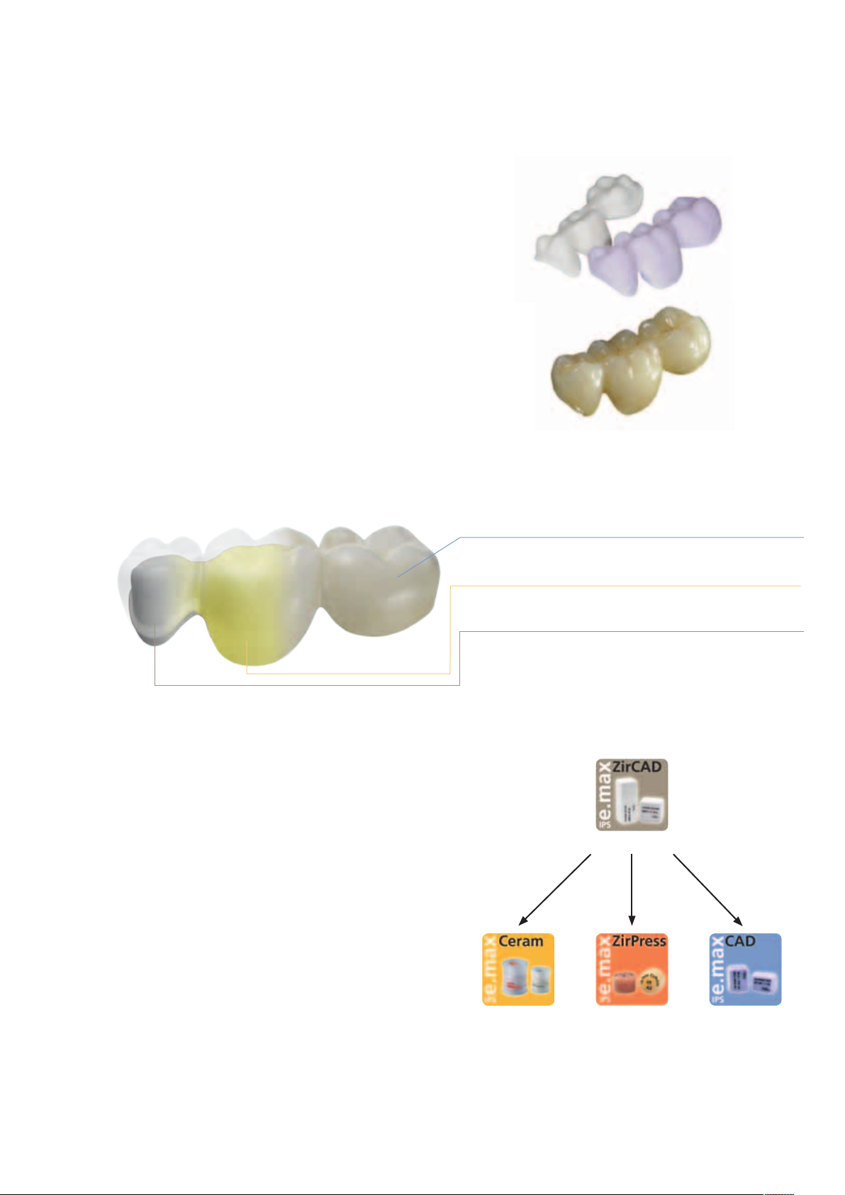
IPS e.max CAD veneering structure
IPS e.max CAD Crystall. /Connect fusion glass- ceramic
IPS e.max ZirCAD framework
Zirconium oxide (ZrO2)
Layering technique
Press-on
technique
CAD-on technique
4
Nano-fluorapatite
glass-ceramic
Fluorapatite
glass-ceramic
Lithium disilicate (LS
Glass-ceramic
)
2
Page 5

Materials for the IPS e.max CAD-on technique
IPS e.max CAD
IPS e.max CAD is a lithium disilicate glass-ceramic
block for the CAD/CAM technique. It is manufactured using an innovative process which
provides an impressive homogeneity of the material.
The block can be processed very easily in a CAD/
CAM unit in this crystalline intermediate stage
(metasilicate). The typical and striking colour of
IPS e.max CAD ranges from whitish to blue and
bluish-grey. This shade is a result of the composition and the microstructure of the glass-ceramic.
The strength of the material in this processable
intermediate phase is 130–150 MPa.
The crystallization takes places in a combined
IPS e.max CAD-on Fusion/Crystallization firing in
an Ivoclar Vivadent ceramic furnace (e.g.
Programat® P700). This leads to a change in the
microstructure in the IPS e.max CAD material,
during of which lithium disilicate crystals grow. The
final physical properties, such as the flexural
strength of 360 MPa, and the desired optical
properties are achieved through the transformation
of the microstructure.
CTE (100-400°C) [10-6 /K] 10.2
CTE (100-500°C) [10-6 /K] 10.5
Flexural strength (biaxial) [MPa]* 360
Fracture toughness [MPa m
Modulus of elasticity [GPa] 95
Vickers hardness [MPa] 5800
Chem. solubility [µg/cm2]* 40
Crystallization temperature [°C] 840 – 850
*according to ISO 6872
0.5
] 2.25
IPS e.max ZirCAD
IPS e.max ZirCAD is a pre-sintered yttrium-
stabilized zirconium oxide block for the CAD/CAM
technique. The blocks are available both shaded
and unshaded. IPS e.max ZirCAD can be processed
very easily in a CAD/CAM unit in its partly sintered,
"chalk-like" state. Milling is carried out with an
enlargement of the framework of approximately
20–25%. Given the controlled manufacturing
process of the blocks, combined with an coordinated sintering process in a high temperature
furnace (e.g. Programat S1) the shrinkage of the
enlarged milled frameworks can be controlled in
such a way that excellent accuracy of fit can be
achieved. During the sintering procedure, the final
material-specific properties of IPS e.max ZirCAD
are achieved. In the process, a structure that is
densified to more than 99% is created, which
features a high flexural strength (>900 MPa) combined with high fracture toughness (5.5 MPa m
0.5
and thus fully meets the clinical requirements
presented by masticatory forces – particularly in
the posterior region.
CTE (100-400°C) [10-6 /K] 10.8
CTE (100-500°C) [10-6 /K] 10.8
Flexural strength (biaxial) [MPa]* 900
Fracture toughness [MPa m
)
0.5
] 5.5
Vickers hardness [MPa] 13000
Chem. solubility [µg/cm2]* 1
Sinter temperature [°C] 1500
*according to ISO 6872
5
Page 6
IPS e.max CAD Crystall./Connect
IPS e.max CAD Crystall./Connect is a specially
developed fusion glass-ceramic which is used to
create a homogeneous bond between the IPS e.
max ZirCAD framework and the IPS e.max CAD
veneering structure during the IPS e.max CAD-on
Fusion/Crystallization firing.
The shades of the fusion glass-ceramic are adjusted
in such a way that the IPS e.max ZirCAD shades
MO 0 to MO 4 combined with the IPS e.max CAD
shades correspond to the shades of the IPS e.max
shade concept. By combining the brighter
IPS e.max ZirCAD framework with the translucent
IPS e.max CAD HT veneering structure and the
harmonizing IPS e.max CAD Crystall./Connect
material, restorations can be fabricated which
exhibit outstanding esthetic properties.
IPS e.max CAD Crystall./Connect
CTE (100-400°C) [10-6 /K] 9.5
CTE (100-500°C) [10-6 /K] 9.2
Flexural strength (biaxial) [MPa]* 160
Chem. solubility [µg/cm2]* 10
Fusion temperature [°C] 840
*according to ISO 6872
1 µm
IPS e.max CAD Crystall./Connect is a pre-dosed,
ready-to-use powder/liquid system available in
single doses and nine shades.
The precisely adjusted powder/liquid mixture of
IPS e.max CAD Crystall./Connect turns liquid when
vibrated (with the Ivomix). This allows the material
to be mixed and the components to be joined on
the Ivomix. Without mechanical influence (vibration) IPS e.max CAD Crystall./Connect turns stable
again, which enables the joined restoration to be
checked in the articulator. This special property is
known as thixotropy.
6
Page 7

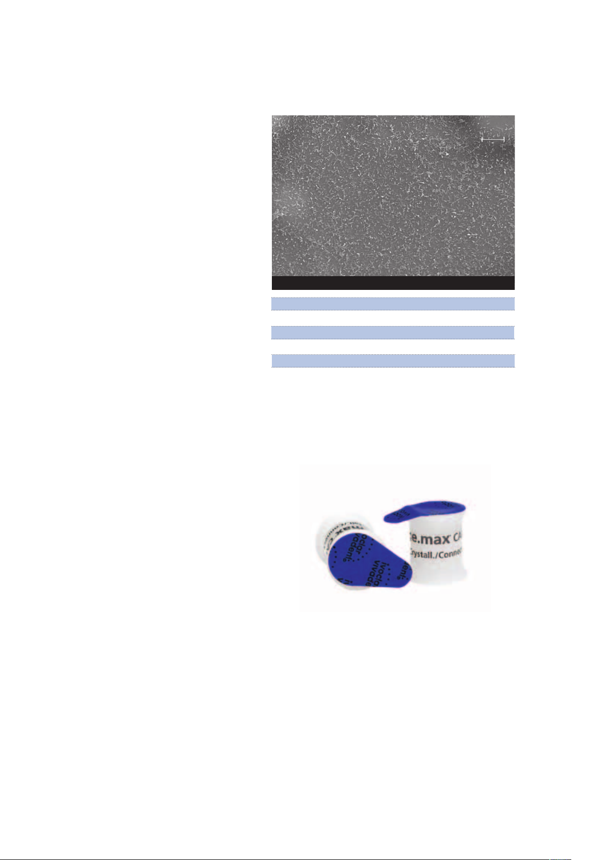
10 µm
After the IPS e.max CAD-on Fusion/Crystallization
firing at 840°C / 1544 °F the sintered material
exhibits a high strength of 160 MPa and forms a
homogeneous bond both to the IPS e.max ZirCAD
freamework and the IPS e.max CAD veneering
structure. This homogeneous bond is clearly visible
on both material interfaces in SEM images.
The sintering temperature of IPS e.max CAD
Crystall./Connect has been adjusted to the
crystallization temperature of IPS e.max CAD so
that the fusion process and the crystallization of
IPS e.max CAD can be conducted in one firing
(Fusion/Crystallization firing).
IPS e.max CAD
IPS e.max CAD Crystall./Connect
IPS e.max ZirCAD
IPS e.max CAD-on fusion area
100 µm
10 µm
The IPS e.max CAD crystallization program was
used as a basis for the IPS e.max CAD-on Fusion/
Crystallization firing. The pre-drying of the restoration including the fusion area is an important partial step of the firing process. As the even drying
of the fusion glass-ceramic takes place through
the fusion gap, the fused restoration must be pre-
dried. The specific pre-drying takes place by
means of a controlled process in a suitable ceramic
furnace. An insufficient or too quick a drying
might result in the veneering structure being
completely or partially lifted off the framework.
Furthermore, the heating rate and the holding
time at 820 °C / 1508 °F have been adjusted so as
to ensure an even heating of the entire restoration. At the end of the program cycle, the longterm cooling has been expanded to 600 °C / 1112 °F.
Due to the complexity of the specially developed
firing program, the ceramic furnace must meet
strict requirements.
7
Page 8

Uses
Indications
− Crowns
− Splinted crowns
− 3- to 4-unit bridges
− Implant superstructure crown
− Implant superstructure splinted crown
− Implant superstructure 3- to 4-unit bridges
Contraindications
− Restorations with more than two connected bridge pontics
− Two bridge pontics as extension units
− Very deep sub-gingival preparations
− Patients with severely reduced residual dentition
− Patients suffering from bruxism
− Any other use not listed in the indications.
− Use of IPS e.max Ceram layering materials (layering technique,
cut-back technique)
− Use of IPS e.max Ceram Glaze, Shades, Essences (staining technique)
Side effects
If patients are known to be allergic to any of the components in the
materials, IPS e.max restorations should not be used.
Composition
– IPS e.max C AD blocks
Components: SiO2
Additional components: Li2O, K2O, MgO, Al2O3, P2O5 and other
oxides
– IPS e.max ZirCAD blocks
Components: ZrO
Additional components: HfO2, A2O3, Y2O3 and other oxides
– IPS e.max ZirCAD Colouring Liquid
Components: Water, ethanol, colouring salts, additives
– IPS e.max CAD Crystall. /Connect
Components: Oxides, water, butandiol and chloride
2
Important note:
The fabrication of IPS e.max CAD HT bridges
which are not supported by a zirconium oxide
structure is contraindicated.
Important processing restrictions
Failure to observe the following restrictions may result in failure and
defective restorations:
− Milling of IPS e.max CAD and IPS e.max ZirCAD with non-
compatible CAD/CAM systems.
− Failure to observe the necessary minimum connector and restoration
thicknesses
− Sintering of IPS e.max ZirCAD in a non-compatible high-temperature
furnace
− Conducting the Fusion/Crystallization firing or the
Characterization/Glaze firing in a ceramic furnace which has not
been approved and which is not recommended
− Conducting the Fusion/Crystallization firing or the
Characterization/Glaze firing with deviating parameters
− Conducting the Fusion/Crystallization firing or the
Characterization/Glaze firing in a non-calibrated ceramic furnace
− Conducting the Fusion/Crystallization firing or the
Characterization/Glaze firing in a high-temperatur furnace (e.g.
Programat S1)
− Mixing of IPS e.max CAD Crystall./Glaze, Shades and Stains with
other ceramic materials (e.g. IPS e.max Ceram Glaze, Stains and
Essences).
− Wetting or rewetting the IPS e.max CAD Crystall./Connect (fusion
glass-ceramic)
− Mixing of IPS e.max CAD Crystall./Connect with other ceramic
materials in general
− Using a vibrator other than Ivomix
– IPS e.max C AD Crystall. /Glaze, Shades and Stains
Components: Oxide, glycols
– IPS e.max CAD Crystall. /Glaze Liquid
Components: Butandiol
– IPS e.max C AD Crystall. /Add-On Incisal, Dentin, Connect
Components: Oxides
– IPS e.max CAD Crystall. /Add-On Liquid allround
Components: Water, butandiol and chloride
– IPS e.max CAD Crystall. /Add-On Liquid longlife
Components: Water, butandiol and chloride
– IPS Object Fix Putty / Flow
Components: Oxides, water, thickening agent
– IPS Contrast Spray Labside
Components: Pigment suspension in ethanol, propellant:
Propane/butane mixture
Warning
– Do not inhale ceramic dust – use exhaust air discharge and mouth
protection.
– IPS Contrast Spray Labside must not be used intraorally.
8
Page 9

Scientific Data
Further scientific data (i.e. strength, wear, biocompatibility) are contained in the “Scientific Documentaion
IPS e.max CAD-on”.
This Scientific Documentation can be obtained from Ivoclar Vivadent.
For further information about all-ceramics in general, please refer to the Ivoclar Vivadent Report No. 16
and 17.
Scientific Documentation
9
Page 10
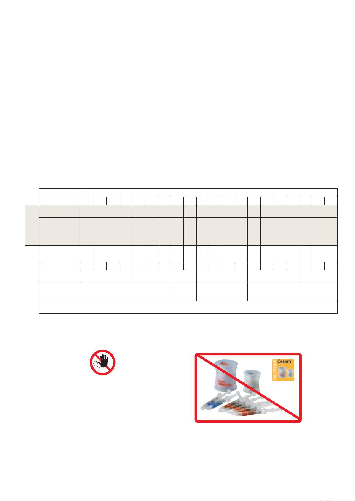
Shade Concept
In the CAD-on technique, the desired restoration shade is the result of the combination of:
− the shade of the framework (IPS e.max ZirCAD MO)
− the shade of the fusion glass-ceramic (IPS e.max CAD Crystall./Connect)
− the shade of the veneering structure (IPS e.max CAD HT)
− characterizations (IPS e.max CAD Crystall./Shades, Stains)
The desired esthetic properties can be specifically achieved if the correct materials which correspond to
the tooth shade are selected.
Note: If other combinations are selected (e.g. different zirconium oxide shades), the final shade may
differ.
Desired tooth shade
BL1 BL2 BL3 BL4 A1 A2 A3 A3.5 A4 B1 B2 B3 B4 C1 C2 C3 C4 D2 D3 D4
IPS e.max ZirCAD
shaded
IPS e.max ZirCAD
non-shaded
+
optional
IPS e.max ZirCAD
Colouring Liquid
IPS e.max CAD
Crystall./Connect
IPS e.max CAD HT
IPS e.max CAD
Crystall./Shade
*
BL11 BL2 BL31BL41A1 A2 A3 A3.5 A41B1 B2 B31B41C1 C2 C31C41D2 D31D4
MO 0 MO 1 MO 2 – MO 1 –
MO 0
1 2 3 4 5 6 9 3 4 7 8 9 8 9
SH 0 SH 1 SH 2 SH 3 SH 4
MO 0
+
CL 1
MO 0
CL 2
MO
MO 0
CL 4
0
+
CL 1
+
+
MO 0
CL 3
IPS e.max CAD
Crystall./Shade
SH I1 SH I2 SH I1 SH I2
Incisal
IPS e.max CAD
Crystall./Stains
*The range of available products may vary from country to country.
1
IPS e.max CAD HT B40 blocks are available in 10 shades. To create the desired tooth shade, select the closest block shade in the respective shade group and determine the final tooth shade by means of Stains.
white, creme, sunset, copper, olive, khaki, mahogany
MO
1
MO
CL 1
0
+
+
MO 0
+
CL 4
1
Note:
Do not use IPS e.max Ceram
layering materials and Shades,
Essences or Glaze materials
in conjunction with the IPS e.max CAD-on
technique.
10
Page 11

Block Concept
Block concept IPS e.max CAD
IPS e.max CAD is basically available in three levels of translucency (HT, LT, MO) and three block sizes
(I12, C14, B40). Depending on the translucency level, different block sizes are available. For esthetic
reasons, IPS e.max CAD HT blocks are used in the IPS e.max CAD-on technique.
Translucency level
High
Translucency
Low
Translucency
Medium
Opacity
CR %
Processing technique
Staining
technique
Cut-back
technique
Layering
technique
CAD-on
technique
Thin
veneers
Indications
Veneers Inlays Onlays Partial
crowns
** IPS e.max CAD-on technique in conjunction with IPS e.max ZirCAD
Anterior
crowns
Posterior
crowns
Splinted
3- to 4-unit
crowns
* up to the second premolar
posterior
bridges
IPS e.max CAD HT (High Translucency)
IPS e.max CAD HT (High Translucency) B40 blocks are available in 9 A–D shades and 1 Bleach BL
shade. For the fabrication of IPS CAD-on bridge restorations, only B40 blocks are used. Due to their
translucency, IPS e.max CAD HT blocks are ideally suitable for the fabrication of IPS e.max CAD-on
restorations in the staining technique. IPS e.max CAD-on restorations fabricated from HT blocks exhibit a
lifelike brightness value and translucency. To characterize and glaze IPS e.max CAD-on restorations, only
the IPS e.max CAD Crystall./Shades, Stains and Glaze are used.
The entire IPS e.max delivery program can be found at
www.ivoclarvivadent.com.
11
Page 12
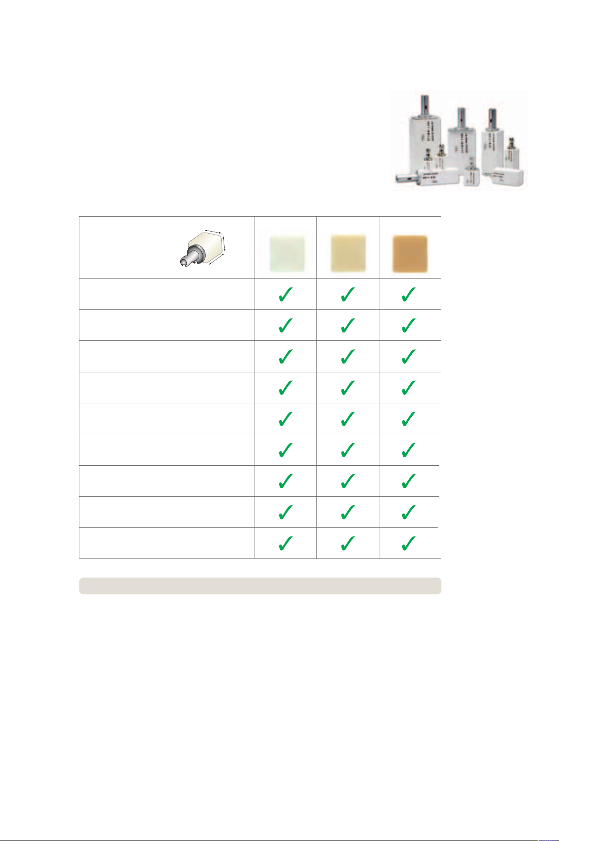
IPS e.max ZirCAD block concept
IPS e.max ZirCAD is currently supplied in 9 block sizes (see table) and 3 shades
(MO 0, MO 1, MO 2). This provides utmost flexibility during block selection, with regard
to both the shade and the block size.
The following IPS e.max ZirCAD blocks are available:
Block designation
Dimensions in mm
(width x length x height)
IPS e.max ZirCAD for inLab
13.2 x 13.2 x 14.0
IPS e.max ZirCAD for inLab
14.5 x 15.5 x 18.5
IPS e.max ZirCAD for inLab
15.4 x 19.0 x 20.0
IPS e.max ZirCAD for inLab
14.2 x 15.5 x 40.0
IPS e.max ZirCAD for inLab
15.4 x 19.0 x 39.0
IPS e.max ZirCAD for inLab
15.5 x 19.0 x 55.0
IPS e.max ZirCAD for inLab
22.0 x 25.0 x 65.0
IPS e.max ZirCAD for inLab
17.0 x 40.0 x 65.0
Length
Width
Height
C 13
C 15
C 15 L
B 40
B 40L
B 55
B 65
B 65 L-17
MO 0 MO 1 MO 2
IPS e.max ZirCAD for inLab
22.0 x 40.0 x 85.0
The entire IPS e.max delivery program can be found at www.ivoclarvivadent.com.
B 85 L-22
12
Page 13

®
IPS
e.max
CAD-on
Clinical Working Steps, Model Preparation
IPS e.max CAD-on technique
Preparation, shade determination,
CAM process
IPS e.max ZirCAD framework
Pre-shaded block
Shading with
Colouring Liquids
Drying
Sintering
Working steps
impression-taking
Model fabrication
Scan and design (CAD)
CAM process
IPS e.max CAD
veneering structure
Finishing/checking
fit of framework and
veneering structure
Ivoclar Vivadent Products
OptraGate
IPS® Natural Die Material
Shade Guide
®
IPS
Contrast Spray Labside
IPS e.max ZirCAD MO
IPS e.max ZirCAD Colouring Liquids
IPS e.max CAD HT
Programat
®
®
S1
Clinical Working Steps, Model Fabrication
*
Fusing framework and
veneering structure
Fusion/Crystallization firing
Characterization/Glaze firing
Preparing for cementation
Conditioning
Cementation
IPS e.max CAD Crystall./Connect
Ivomix
IPS e.max CAD Crystall./
Shades, Stains, Glaze, Add-On
IPS e.max CAD Crystallization
IPS Object Fix Putty and Flow
P300, P500, P700, EP 5000
Monobond
Multilink
Tray and Pins
Programat
®
Plus
®
Automix
SpeedCEM
Vivaglass® CEM
bluephase
®
Check of articulation / occlusion
+ polishing
(after intraoral adjustment)
Recall
®
OptraFine
Proxyt
13
*The range of available products may vary from country to country.
®
Page 14

Shade Determination – Tooth Shade, Shade of the Prepared
Tooth
Optimum integration in the oral cavity of the patient is the prerequisite for a true-to-nature all-ceramic
restoration. To achieve this, the dentist must observe the following guidelines and notes.
The overall esthetic result of an all-ceramic restoration is influenced by the following factors:
• Shade of prepared tooth (natural preparation, core build-up, abutment, implant)
• Shade of the restoration (framework shade, veneer, characterization)
• Shade of the cementation material
The optical effect of the preparation shade must not be underestimated during the fabrication of highly
esthetic restorations. For that reason, the shade of the preparation should be determined together with
the desired tooth shade in order to select the suitable block. Especially with severely discoloured preparations or non-tooth-shaded build-ups, this is of utmost importance. In order to achieve the desired esthetics,
the shade of the prepared tooth must first be determined.
Preparation Shade
– Prepared natural tooth
– Core build-up
– Implant, abutment
Desired tooth shade
Cementation material
Responsibility of the Dental Office Responsibility of the Laboratory
Shade determination of the natural tooth
After tooth cleaning, the tooth shade of the non-prepared tooth and/or the adjacent teeth is
determined with the help of a shade guide. Individual characteristics have to be considered when
determining the tooth shade. If a crown preparation is planned, for example, the cervical shade should
also be determined. In order to achieve the best possible true-to-nature results, shade determination
should be carried out at daylight. Furthermore, the patient should not wear clothes of intensive colours
and/or lipstick.
Restoration Shade
– Framework shade
– Veneer
– Characterization
Die shade selection
In order to facilitate the reproduction of the desired tooth shade, the shade of the preparation is
determined with the help of the IPS Natural Die Material shade guide. This enables the technician to
fabricate a model die similar to the preparation of the patient, on the basis of which
the correct shade and brightness values of the all-ceramic restorations may
be selected.
14
Page 15
Preparation Guidelines
Basic preparation guidelines for all-ceramic restorations
– No angles or edges
– The incisal edge of the preparation, particularly for anterior teeth, should be at least 1.0 mm (milling
tool geometry) in order to permit optimum milling during CAD/CAM processing.
1.0
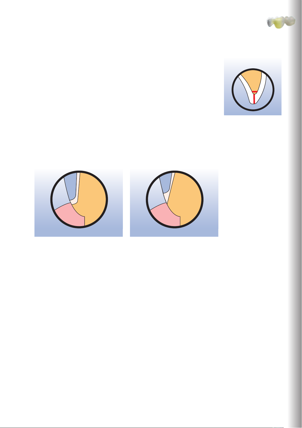
The following notes should also be observed when using the IPS e.max CAD-on technique:
The zirconium oxide framework is designed in the software with a circumferential collar on abutment
teeth / crown framework due to technical reasons. The height of this collar is mainly determined by the
shape of preparation and the designed fully anatomical tooth shape.
– A very pronounced shoulder/chamfer results in a thin zirconium oxide collar.
– A minor shoulder/chamfer results in a wider zirconium oxide collar.
A very pronounced shoulder/chamfer results in
a thin zirconium oxide collar.
A minor shoulder/chamfer results in a wider
zirconium oxide collar.
1.5
Clinical Working Steps, Model Fabrication
15
Page 16
1.0
1.5
1.0
1.5
2.0
1.0
1.5
2.0
1.0
1.0
1.5
2.0
1.5
6°
1.0
1.0
1.5
1.5 1.5
1.0
1.0
1.0
1.5
1.5 1.5
1.0
1.5
1.5
1.0
1.0
1.5
1.5
1.5
6°
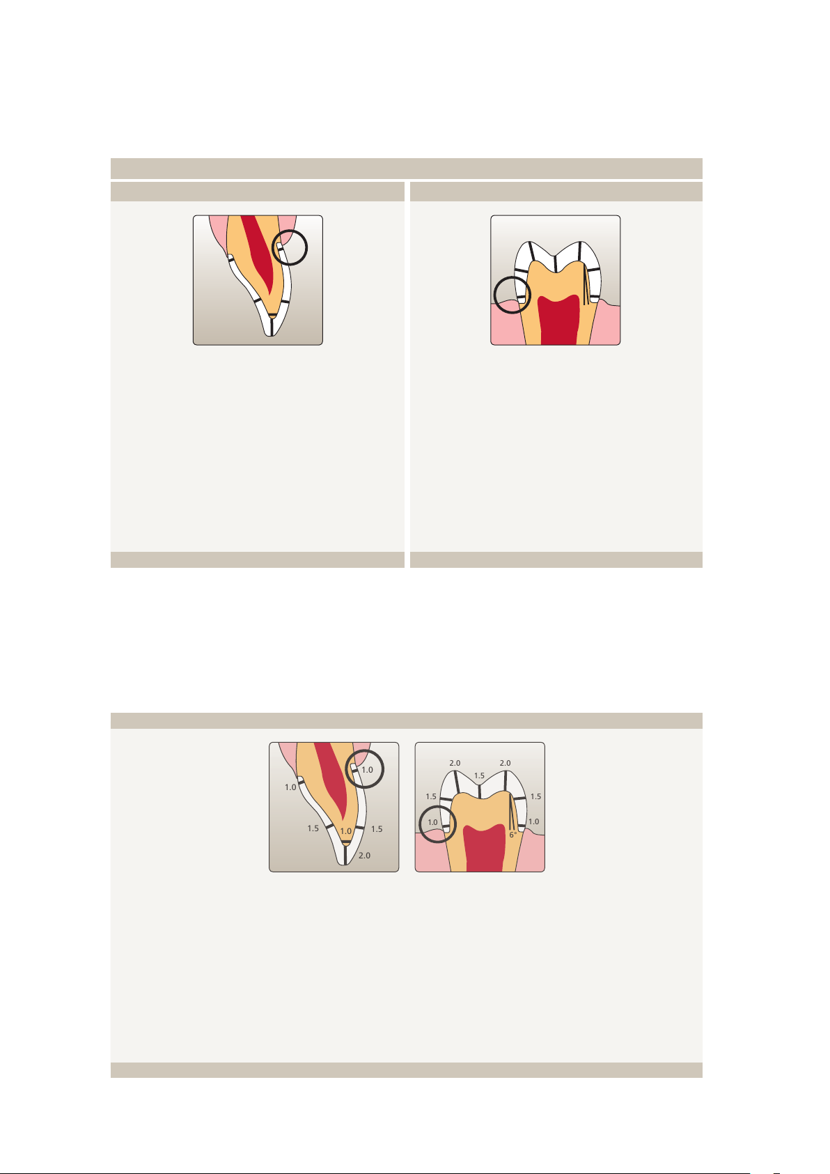
Singe Crowns to 3-Unit Bridges
Anterior Crown
− Reduce the anatomical shape and observe the stipulated
minimum thickness. Prepare a circular shoulder with
rounded inner edges or a chamfer at a degree of
approximately 10°-30°. Width of the circular shoulder/
chamfer at least 1.0 mm.
− Reduce the incisal crown third by approx. 1.5 mm.
Reduce the vestibular and/or oral area by approx.
1.5 mm.
− For conventional and/or self-adhesive cementation,
the preparation must demonstrate retentive surfaces.
Posterior Crown
− Reduce the anatomical shape and observe the stipulated
minimum thickness. Prepare a circular shoulder with
rounded inner edges or a chamfer at a degree of
approximately 10°-30°. Width of the circular shoulder/
chamfer at least 1.0 mm.
− Reduce the incisal crown third by approx. 1.5 mm.
Reduce the vestibular and/or oral area by approx.
1.5 mm.
− For conventional and/or self-adhesive cementation,
the preparation must demonstrate retentive surfaces.
4-Unit Bridges
− Evenly reduce the anatomical shape and observe the stipulated minimum thickness. Prepare a circular shoulder
with rounded inner edges or a chamfer with a width of at least 1.0 mm.
− Reduce the incisal crown third – incisal and/or occlusal - by approx. 1.5 mm.
− For anterior crowns, the reduction in the labial and/or palatal/lingual area is at least 1.5 mm. The incisal edge of
the preparation should be at least 1.0 mm (milling tool geometry) in order to permit optimum milling of the incisal area during CAD/CAM processing.
− For posterior crowns, the reduction in the buccal and/or palatal/lingual area is at least 1.5 mm.
− For conventional and/or self-adhesive cementation, the preparation must demonstrate retentive surfaces
16
Page 17

Model Preparation
Please observe the instructions of the manufacturer of the CAD/CAM system for the selection of the
model material.
Important for the fabrication of models:
− Check the radius of the incisal/occlusal edge on the prepared tooth (maxilla and mandible).
− The prepared incisal/occlusal edge should be at least as thick as the diameter of the bur used in the
cavity during the CAD/CAM process.
− If the incisal/occlusal edge of the prepared die is thinner than the diameter of the bur, the edge has to
be blocked out accordingly.
− The preparation margins must be clearly defined so that they are clearly recorded during scanning.
− Do not apply a die varnish or spacer.
− In clinical cases with a very thin alveolar ridge, the lingual/palatal side of the ridge must be
supplemented with putty silicone or a similar material. This allows the dimensions of the bridge pontic
to be correctly designed during the subsequent design of the restoration.
Clinical Working Steps, Model Fabrication
A stone model is used as a working model.
In clinical cases with a very thin alveolar ridge, the lingual/palatal side must be blocked out on the model.
17
Page 18

Layer Thicknesses
The restoration design is key to the success of durable all-ceramic restorations.
The more attention given to the design, the better the final results and the clinical success will turn out to be. The
following basic guidelines have to be observed:
– The restoration design generated by the software may need to be individually adapted according to the clinical require-
ments using the design tools.
– In the case of bridges, a sufficient penetration of the individual bridge elements must be ensured in order to observe the
minimum connector dimensions in the IPS e.max CAD-on restoration.
– During the construction of an IPS e.max CAD-on restoration, the separation into IPS e.max ZirCAD frame-
work and the IPS e.max CAD veneering structure is carried out by the software after the design of an anatomical shape.
– If changes are made to the framework during construction in the milling preview, make sure that no undercuts are created.
Otherwise, the IPS e.max CAD veneering structure may not be placed on the framework.
– After the milling process, only the attachment point to the block may be smoothed out on the IPS e.max ZirCAD frame-
work. Further processing is not possible, as this would influence the size of the fusion joint.
The following minimum layer thicknesses are stored in the software and must be observed. Please refer to the
indications (see page 8) for information on the possible restorations.
IPS e.max IPS e.max CAD
veneering structure
minimum layer thickness
IPS e.max ZirCAD
framework minimum layer
thickness
circular
occlusal
circular
occlusal
Connector dimensions
Crowns Splinted
crowns
3-unit posterior
bridges
4-unit posterior
(2 connected bridge pontics
0.7 0.7 0.7 0.7
0.7 0.7 0.7 0.7
0.5 0.5 0.5 0.5
0.5 0.5 0.5 0.7
— — 9 mm
2
bridges
at most)
12 mm
Dimensions in mm
2
18
Page 19

®
IPS
e.max
CAD-on
CAD/CAM Processing
CAD process with Sirona inLab 3D Software
The inLab 3D software V3.81 or higher is necessary to fabricate IPS e.max CAD-on restorations with the Sirona inLab®
system. The basic operation and function of this software is described in the respective "inLab 3D Operator's Manual".
In addition to the Manual, the following notes on the construction of IPS e.max CAD-on restorations must be observed.
The description is not conclusive and does not include all required details; it is limited to the steps which are relevant in the
context of the IPS e.max CAD-on technique.
In the New dialog, e.g. for the creation of a bridge
restoration, make the following selection:
Restoration: Bridge
Design technique: Multilayer
CAD/CAM Processing
The "Multilayer" design technique is the software
tool that is used to create IPS e.max CAD-on
restorations.
After the model or prepared teeth have been
scanned the restorative materials are selected.
With this step, the material thicknesses that apply
to the respective material are activated for the
subsequent design.
Framework: Ivoclar Vivadent IPS e.max ZirCAD
Veneering structure: Ivoclar Vivadent IPS e.max CAD
Make the following individual settings for the framework in the Parameter dialog box:
– Oclusal contact strength: e.g. -50 µm
–> influences the strength of the contact points
– Spacer: e.g. 0 µm
–> individual setting according to the required fit
on the model
– Lingual open angle: 0° – 45°
–> depends on the clinical case at hand or the
desired restoration geometry
19
Page 20

Determination of the preparation margins and entering the base line
of the bridge pontic in bridge restorations.
Note: The base line defines the dimensions of the bridge pontic rest in the design mode Multilayer and thus the dimensions
of the framework.
Example: clinical case with thin alveolar ridge
The base line is entered on the "gingiva" and on the blocked-out
part of the model (cf page 17 Model preparation) so that the desired
bridge pontic rest can be achieved.
Example: clinical case with thin alveolar ridge
–> with no blocking-out of the thin alveolar ridge, the base line
cannot be entered correctly.
Note on the optimum selection of the insertion axis:
An inadequate insertion axis selection (see image: model is inclined
too far to the buccal aspect) may result in a wide zirconium oxide
collar on the framework.
The insertion axis should therefore be determined in such a way to
allow an optimum view of all preparation shoulders of the abutment
teeth.
In difficult cases, it is advisable to rather incline the model to the
palatal/lingual side to achieve an optimum design of the restoration
on the buccal side.
20
Page 21

The automatically generated framework suggestion can be adjusted
to the clinical situation using the design tools.
If bridges are fabricated, a sufficient penetration of the bridge
pontics must be observed. The penetration defines the total
surface of the connector cross section (framework and
veneering structure).
An insufficient connector cross section area is indicated by a display
highlighted with a red background (in the footer) The penetration of
the bridge components must be increased with the Design tools.
The lingual open angle (0° -45°) can be changed in the Parameter
dialog box.
After the angle has been entered, the changes become effective by
editing a small segment of the base line.
CAD/CAM Processing
When changing to the milling preview, the segmentation of the
restoration into "Framework" and "Veneer structure" (transparent)
takes place automatically.
If required, smooth out the occlusal surface (e.g. in case of protruding pontics) by means of the Design tools.
Observe the minimum layer thicknesses!
The circular surfaces must not be edited with the
Design tools, as this would compromise the fit of the
veneering structure.
21
Page 22

Load the veneering structure to the milling preview in the Design
menu by clicking on Editing the veneering structure
Note: The milling procedure for the framework should start only
now (see next image), as the milling preview of the veneering
structure can otherwise not be loaded.
Select the Endo mode in the milling preview in order to ensure that
an even joint gap is achieved between framework and veneering
structure.
Select Ivoclar Vivadent IPS e.max ZirCAD in the block selection and
the desired block size prior to the milling process for the framework.
Then start the milling process.
Select Ivoclar Vivadent IPS e.max CAD in the block selection and the
desired block size prior to the milling process for the veneering
structure. Then start the milling process.
22
Page 23

CAM process with Sirona inLab® MC XL
The milling process of the IPS e.max ZirCAD framework and the
IPS e.max CAD veneering structure takes place in a Sirona InLab MC XL
milling unit. Please refer to Sirona's recommendations with regard to
suitable milling tools.
For the milling process in a Sirona inLab MC XL unit, please observe the
Ivoclar Vivadent recommendations with regard to the Dentatec milling
additive.
CAD/CAM Processing
Milled IPS e.max ZirCAD framework Milled IPS e.max CAD veneering structure
23
Page 24

®
VE R AR B EI T UN G SA N LE I T UN G
ZirCAD
all ceramic
all you need
IPS
e.max
CAD-on
Finishing of the Framework and
Veneering Structure
Completing the IPS e.max ZirCAD framework.
Note: For detailed information on the processing of IPS e.max ZirCAD please refer to the IPS e.max ZirCAD
Instructions for Use.
Finishing Drying Sintering Checking
Finishing
As a general rule, manual grinding of the IPS e.max ZirCAD framework should be limited in the IPS e.max CADon technique to smoothing out the attachment point to the block.
The circular collar at bridge pontics and crown frameworks generated by the software must not
be ground, as this might compromise the accuracy of fit between the IPS e.max ZirCAD framework and the IPS e.max CAD veneering structure.
It is of critical importance to use the correct grinding instruments for adjustments of the attachment point on the
IPS e.max ZirCAD framework. If unsuitable grinding instruments are used, e.g. chipping of the edges may occur (please
observe the Ivoclar Vivadent Flow Chart "Recommended grinding tools for PS e.max zirconium oxide").
The following procedure is recommended for finishing IPS e.max ZirCAD frameworks:
– The presintered zirconium oxide framework is prone to damages and fractures and must therefore be handled with
care.
– Rinse the milled IPS e.max ZirCAD framework under slightly running water directly after the milling process to remove
all milling residue. Subsequently, carefully blast with compressed air.
– Carefully separate the milled IPS e.max ZirCAD framework from its holder using a diamond-coated separating disk.
– Check the layer thickness next to the attachment point with calipers and reduce the IPS e.max ZirCAD
framework at the attachment point to precisely this layer thickness. Smooth out the attachment point
with suitable grinding instruments.
– Do not use fine rubber polishers for finishing IPS e.max ZirCAD frameworks to be shaded with an infiltration solution,
since this will seal the surface and result in uneven shading.
– Rough tungsten carbide burs and burs with large diameters are not suitable, as the vibrations during finishing might
result in chipping. Therefore, only fine tungsten carbide burs and grinding instruments with small diameters should be
used.
– Do not "post-separate" the bridge framework with separating disks. This may result in undesired predetermined
breaking points, which may cause the restoration to fracture.
– After finishing, clean the IPS e.max ZirCAD framework with compressed air to remove grinding dust. If the framework
is still moist, additionally clean it under running water.
– Make sure that all grinding residue (e.g. grinding dust) is removed. Adhering grinding dust may get fused to the
framework during sintering and result in inaccuracy of fit.
– The IPS e.max ZirCAD framework must not be cleaned with ultrasound in a water bath or with a steam jet.
– The IPS e.max ZirCAD framework must not be blasted with Al2O3 or glass polishing beads.
Optional
Shading
24
Page 25

coated separating disk.
Do not grind the circular collar created by the software on the IPS e.max ZirCAD framework.Carefully separate the milled IPS e.max ZirCAD framework from its holder using a diamond-
Finishing of the Framework and Veneering Structure
Do not "post-separate" the bridge framework with a separating disk.
Check the layer thickness next to the attachment point and reduce the IPS e.max ZirCAD framework at the attachment point to this layer thickness.
Do not smooth out rough areas on the IPS e.max ZirCAD framework surface, as this
Smooth out the attachment point with suitable grinding instruments.
Observe the minimum layer thickness of the IPS e.max ZirCAD framework!
unnecessarily increases the size of the joint.
Comparison: Attachment point area before (left) and after (right) grinding.
Comparison: IPS e.max ZirCAD framework after CAM process (above)
and after correction of the attachment point (below).
25
Page 26

Finishing Drying Sintering Checking
IN S T R U C T I O N S
FO R
US E
ZirCAD
all ceramic
all you need
Finishing Drying Sintering Checking
Optional
Shading
Drying
In order to prevent damaging the IPS e.max ZirCAD framework during sintering, the IPS e.max ZirCAD framework must be
completely dried. Moist IPS e.max ZirCAD frameworks must not be sintered.
Please observe the following notes for drying:
– The IPS e.max ZirCAD framework must be free of dust and grinding residue.
– The framework can be dried either in a drying cabinet or under an infrared lamp.
Place the IPS e.max ZirCAD framework on the occlusal surface for drying.
– Note: If infrared lamps (250 W) are used, the distance (5-20 cm) to the object decisively influences the
temperature that develops.
– The drying time depends on the temperature. For drying the frameworks, a temperature of
140 °C (284 °F) must not be exceeded. With lower temperatures, the drying times are prolonged.
– The drying time also varies with the size of the IPS e.max ZirCAD framework. The following table
contains the required drying times.
Temperature ~70 °C / 158°F Temperature ~140 °C / 284°F
Single-tooth frameworks
≥15 min
5 – 10 min
3-4-unit bridge frameworks
≥40 min
Finishing Drying Sintering Checking
≥25 min
Optional
Shading
Shading (optional)
For shading the IPS e.max ZirCAD MO 0 frameworks, four Colouring Liquids (CL1-CL4) are available*. With the shading,
the framework shade is adjusted to the IPS e.max shade concept. The allocation to the desired tooth shade is listed in the
combination table (page 50).
Note: For the detailed procedure regarding shading with IPS e.max ZirCAD Colouring Liquids, please refer to the
IPS e.max ZirCAD Instructions for Use.
Comparison of shaded IPS e.max ZirCAD before and after sintering.
IPS e.max ZirCAD shaded
before sintering
IPS e.max ZirCAD shaded
after sintering
Note on the use of IPS e.max ZirCAD Colouring Liquids
The frameworks shaded with IPS e.max ZirCAD Colouring Liquids must be sufficiently pre-dried in a pre-drying furnace! Air
drying is not sufficient and might result in the formation of cracks in the framework during the sintering process in the
Programat S1.
*The range of available products may vary from country to country.
26
Page 27

Finishing Drying Sintering Checking
Optional
Shading
Sintering
The high-temperature Programat S1 furnace is preferably used for sintering IPS e.max ZirCAD frameworks. The furnace's
programs are optimally adjusted to IPS e.max CAD and the material's shrinkage during sintering and thus allow optimum
results to be achieved.
Prior to sintering, allow the IPS e.max ZirCAD frameworks to dry for a sufficient amount of time according to the size
(page 26). Please keep in mind that IPS e.max ZirCAD frameworks which are sintered while moist are damaged as a result
to the high heating rate.
For the sintering process in the Programat S1, the following points should be observed: Positioning of dried
IPS e.max ZirCAD frameworks on the sintering tray supplied with Programat S1:
– Do not use ZrO
sintering beads in the Programat S1.
2
– The sinter tray can be entirely filled with IPS e.max ZirCAD frameworks. Make sure that the frameworks do not
touch each other.
– Simultaneous sintering of single-tooth and bridge frameworks as well as frameworks with a sinter support
structure is possible.
– Observe the program selection.
– Provide even support for the IPS e.max ZirCAD frameworks.
– Bridge frameworks should not exclusively be supported by the abutment crowns. The bridge pontic must
be supported. The abutment crowns do not absolutely have to come into contact with the sinter tray.
Observe the notes in the IPS e.max ZirCAD Instructions for Use!
– Arrange the IPS e.max ZirCAD frameworks in concentric circles on the sinter tray, particularly bridge frameworks.
Important: Do not place any frameworks over the separation in the sinter tray.
– Place the loaded sinter tray in its intended position in the centre of the sintering chamber of the Programat S1 using the
sinter tray fork.
Finishing of the Framework and Veneering Structure
Arrange the frameworks in concentric circles on the sinter tray. This ensures even temperature
distribution within the framework during heating and cooling.
Frameworks with or without sinter support structure may be sintered simultaneously.
Observe the program selection. The frameworks must not touch each other.
Do not place any frameworks over the separation in the sinter tray.
Select the sintering program in accordance with the materials used (e.g. use of IPS e.max ZirCAD Colouring Liquids) and
the indications (single-tooth or bridge framework) and start the process.
Remove the sinter tray from the Programat S1 after the sintering process using the sinter tray fork. Always allow the hot
IPS e.max ZirCAD frameworks to cool to room temperature before proceeding.
For details on the sintering process, please refer to the IPS e.max ZirCAD Instructions for Use and the Programat S1
Operating Instructions.
More information can be found at www.ivoclarvivadent.com.
27
Page 28

Finishing Drying Sintering Checking
Optional
Shading
Checking on the model
Once the IPS e.max ZirCAD framework has cooled to room temperature, proceed with the following steps:
– Remove the IPS e.max ZirCAD framework from the sinter tray and carefully place it on the model.
– Check the fit of the IPS e.max ZirCAD framework on the model / the dies.
– Do not grind the outer aspect of the IPS e.max ZirCAD framework, in order to prevent an inaccurate fit
between the IPS e.max ZirCAD framework and the IPS e.max CAD veneering structure.
– Do not "post-separate" the bridge framework with separating disks after sintering, since this may result
in undesired predetermined breaking points, which may cause the restoration to break.
– If corrections by grinding are necessary to fit the framework on the model or the dies, use suitable grinding instruments.
For the selection of the grinding instruments, please refer to the "Recommended grinding tools for IPS e.max zirconium
oxide".
– Use rotary instruments and low pressure for grinding. The instructions of the manufacturer of the grinding instruments
must be observed.
– Make sure that the minimum layer thicknesses are observed.
– Finally, clean the IPS e.max ZirCAD framework under running water or with a steam jet cleaner and dry.
– The IPS e.max ZirCAD framework must not be blasted with Al2O3 or glass polishing beads, as this would damage the
ceramic surface and compromise the bond.
Do not grind the outer aspect of the IPS e.max ZirCAD framework, in order to prevent an
inaccurate fit between the IPS e.max ZirCAD framework and the IPS e.max CAD veneering structure.
Completely prepared IPS e.max ZirCAD framework on the model.
Do not "post-separate" bridge frameworks with separating disks, as this would create
predetermined breaking points.
28
Page 29

Completing the IPS e.max CAD Veneering Structure
IN S T R U C T I O N S
FO R
US E
CAD
LAB SID E
all ceramic
all you need
Note: For detailed information on the processing of IPS e.max CAD please refer to the IPS e.max CAD
Instructions for Use.
Finishing
Fitting
to the framework
Checking
Occlusion, articulation,
contact points
Finishing, adjusting, checking
It is of critical importance to use suitable instruments for finishing IPS e.max CAD. If unsuitable grinding instruments are
used, chipping of the edges and local overheating may occur (please observe the Ivoclar Vivadent Flow Chart
"Recommended grinding tools for PS e.max glass-ceramics").
Carry out adjustments by grinding of IPS e.max CAD veneering structures while they are still in their pre-crystallized (blue)
state, if possible.
– Only use suitable grinding instruments, low speed and light pressure to prevent delamination and chipping at the
margins in particular.
– Overheating of the glass-ceramic must be avoided.
Observe the following procedure for finishing IPS e.max CAD veneering structures:
– Carefully separate the IPS e.max CAD veneering structure from the block using a diamond-coated separating disk.
– Place the IPS e.max CAD veneering structure on the sintered IPS e.max ZirCAD framework and check the fit. The
IPS e.max CAD veneering structure must touch the entire circular collar of the bridge abutment or the crown framework.
– If corrections are required to adjust the IPS e.max CAD veneering structure to the IPS e.max ZirCAD framework, always
carry out the corrections on the IPS e.max CAD veneering structure.
− The IPS e.max ZirCAD framework and the IPS e.max CAD veneering structure must touch each other only at the
cervical collar, in order to ensure a correct subsequent fusion with the IPS e.max CAD Crystall./Connect fusion glassceramic.
− In the case of bridges, IPS e.max CAD veneering structure and the IPS e.max ZirCAD framework must not touch each
other in the basal pontic area. Adjust by grinding, if necessary.
Completing the IPS e.max CAD Veneering structure
– Finish the outer aspects of the IPS e.max CAD veneering structure with rubber polishers. The veneering structure can be
placed on the IPS e.max ZirCAD framework in order to prevent excessive reduction.
– Do not separate the interdental space with separating disks. The interdental space can be adjusted with fine,
tapered diamond burs or diamond-coated rubber wheels. "V-shaped" cuts have to be avoided.
– Carefully smooth out the attachment point on the restoration. Pay attention to the proximal contact.
– Place the restoration (IPS e.max ZirCAD framework with IPS e.max CAD veneering structure in place) on the model.
Check occlusal contact points and articulation in the articulator. Carry out individual corrections, if required.
– Surface-grind the entire occlusal surface of the IPS e.max CAD veneering structure with a fine diamond to smooth out
the surface structure created by the CAD/CAM procedure.
– Make sure that the minimum layer thicknesses are observed.
– Design surface textures.
– Clean the IPS e.max ZirCAD framework and the IPS e.max CAD veneering structure with ultrasound in a water bath or
blast with the steam jet before further processing.
– Make sure to thoroughly clean the restoration before further processing and to remove any residue of the milling
additive of the CAD/CAM milling unit. Residue of the milling additive remaining on the surface may result in bonding
problems and discolouration.
– Do not blast restorations with Al
or glass polishing beads!
2O3
29
Page 30

Carefully separate the IPS e.max CAD veneering structure from the block using a diamond-coated separating disk.
Place the IPS e.max CAD veneering structure on the IPS e.max ZirCAD framework
and check the fit.
If corrections of the fit are required, always carry out the corrections on the IPS e.max CAD
veneering structure.
In the case of bridges, the IPS e.max CAD veneering structure and the IPS e.max ZirCAD framework must not touch each other in the basal pontic area.
The contact area between the IPS e.max CAD veneering structure and the IPS e.max ZirCAD
Finish the margins of the IPS e.max CAD veneering structure with suitable instruments.
The veneering structure can be placed on the IPS e.max ZirCAD framework for this procedure.
framework is limited to the collar.
Do no t separate the interdental space with separating disks.
The interdental space can be adjusted with tapered diamond burs or diamond-coated rubber
wheels. "V-shaped" cuts have to be avoided.
30
Page 31

Completely fitted IPS e.max CAD-on restoration prior to the fusion process.Smooth out the attachment point with suitable grinding instruments.
Check the occlusion and articulation as well as the proximal contact points on the model.
Completing the IPS e.max CAD Veneering Structure
Surface-grind the occlusal surface, particularly functional areas of the restoration, with a fine
diamond to smooth out the surface structure created by the CAD/CAM process.
Pay attention to the contact points.
Design surface textures. Pay attention to the contact points.
Do not blast the IPS e.max ZirCAD framework with Al2O3 or glass polishing beads!Do not blast the IPS e.max CAD veneering structure with Al2O3 or glass polishing beads.
31
Page 32

®
e.max
IPS
CAD-on
Glass-ceramic Fusion Process
The IPS e.max CAD Crystall./Connnect fusion glass-ceramic is used to
fuse the IPS e.max CAD veneering structure to the IPS e.max ZirCAD
framework. The Ivomix (vibrator unit) is used for the processing of the
fusion glass-ceramic.
IPS e.max CAD Crystall. /Connect is already predosed and ready for use as Single Dose and must not
be diluted. The addition of liquids results in a
defective fusion of the restoration. The material's
consistency is adjusted in such a way that optimum
fusion is achieved.
Preparation
Preparation Fusion process
To prepare for the fusion process, please observe the following procedure:
– Select the suitable IPS e.max CAD Crystall./Connect material on the basis of the desired tooth shade according to the
combination table (p. 50).
– Press the Ivomix onto a smooth work surface and switch it on. Please refer to the respective Operating Instructions for
more details on the Ivomix.
– To mix the material, lightly press the closed IPS e.max CAD Crystall./Connect capsule onto the vibrating plate of the
Ivomix for approx. 10 seconds and slightly agitate it.
– Completely remove the sealing lid from the capsule.
– Make sure that the material has been properly mixed and that it shows a homogeneous consistency. Use the IPS Spatula
for this purpose. If required, mix with the IPS Spatula while vibrating the capsule.
– Do not add any liquid.
Cleaning,
checking
Fusion/
Crystallization
firing
Firmly press the Ivomix onto a smooth work surface. If required, slightly moisten the suction
cups beforehand.
Completely remove the sealing lid from the capsule.
Lightly press and agitate the close d capsule on the vibrating plate of the Ivomix
Make sure that the material has been properly mixed and that it shows a homogeneous
32
consistency. Use the IPS Spatula for this purpose.
for approx. 10 seconds.
Page 33

Fusion/
Crystallization
firing
Fusion Process
Preparation Fusion process
Cleaning,
checking
The fusion process must be completed quickly in order to prevent a permature drying of the IPS e.max CAD
Crystall. /Connect fusion glass-ceramic. The amount of IPS e.max CAD Crystall./Connect contained in one capsule is
sufficient for a 4-unit bridge. Please observe the following procedure for the fusion process:
– Place the open capsule on the finger clip and put on the finger clip.
– Place some IPS e.max CAD Crystall./Connect on the occlusal aspect of the IPS e.max ZirCAD framework in order to avoid
hollow spaces in the fusion area. Evenly distribute the IPS e.max CAD Crystall./Connect material by vibrating it for a
short time with the Ivomix.
– Remove small amounts of IPS e.max CAD Crystall./Connect with the IPS Spatula and distribute it on all inner aspects of
the IPS e.max CAD veneering structure.
– Hold occlusal surface of the IPS e.max CAD veneering structure against the vibrating plate of Ivomix for a short time so
that the IPS e.max CAD Crystall./Connect material is evenly distributed.
– Insert the IPS e.max ZirCAD framework in the correct position into the IPS e.max CAD veneering structure.
– Hold the occlusal surface of the restoration against the vibrating plate of the Ivomix. At the same time, apply slight
pressure against the IPS e.max ZirCAD framework, e.g. by means of the IPS Spatula, in order to evenly insert it into the
IPS e.max CAD veneering structure.
– When joining the IPS e.max ZirCAD framework and the IPS e.max CAD veneering structure, the IPS e.max
CAD Crystall. /Connect material must be evenly squeezed out of the entire circular fusion joint. If no fusion
glass- ceramic is being squeezed out in some places, an insufficient amount of material has been applied to
the IPS e.max CAD veneering structure, and the entire procedure must be repeated with a new capsule.
Separate and clean the IPS e.max ZirCAD framework and the IPS e.max CAD veneering structure under run-
ning water before repeating the procedure.
– The IPS e.max CAD veneering structure is in the correct position when it sits flush on the collar of the IPS e.max ZirCAD
framework.
– Important: Hold the restoration against the vibrating plate of the Ivomix only until the IPS e.max ZirCAD framework
and the IPS e.max CAD veneering structure are in the correct position to one another. A longer vibrating process may
result in too much IPS e.max CAD Crystall./Connect material escaping.
– Switch off the Ivomix.
– The IPS e.max ZirCAD framework and the IPS e.max CAD veneering structure are in a firm position when the restoration
is no longer being vibrated.
Glass-ceramic Fusion Process
work and ...
Remove the IPS e.max CAD Crystall./Connect with the IPS Spatula from the capsule and distribute it on the inner aspect of the IPS e.max CAD veneering structure and ...
... evenly distribute the IPS e.max CAD Crystall./Connect material by means of the vibrator.Apply IPS e.max CAD Crystall./Connect on the occlusal aspect of the IPS e.max ZirCAD frame-
33
Page 34

... evenly distribute the IPS e.max CAD Crystall./Connect material by means of the vibrator.
Insert the IPS e.max ZirCAD framework in the correct position into
the IPS e.max CAD veneering structure.
Hold the occlusal surface of the restoration against the vibrating plate of the Ivomix. At the
same time, apply slight pressure against the IPS e.max ZirCAD framework in order to evenly
insert it into the IPS e.max CAD veneering structure.
The IPS e.max CAD veneering structure is in the correct position when it sits evenly on the
Preparation Fusion process
ridge of the IPS e.max ZirCAD framework.
Cleaning,
checking
Fusion/
Crystallization
firing
Cleaning, Checking
After the fusion process, the restoration is cleaned and the fusion result is checked. To do so, observe the following
procedure:
– Before cleaning, allow the restoration to dry for a short time.
– Carefully remove excess IPS e.max CAD Crystall./Connect material from the occlusal and proximal area as well as around
the restoration margins by means of the IPS Spatula.
– Smooth out the IPS e.max CAD Crystall./Connect material at the fusion joint.
– Carefully remove all residue of IPS e.max CAD Crystall./Connect material from the IPS e.max CAD veneering structure
(e.g. occlusal aspect) by means of the IPS Spatula or a dry short-haired brush.
– Check the cavities of the IPS e.max ZirCAD framework, remove any residue of IPS e.max CAD Crystall./Connect material
with the IPS Spatula or a brush.
– Checking in the articulator: Is the final occlusal position achieved? If not, the IPS e.max ZirCAD framework and the
IPS e.max CAD veneering structure have not been correctly joined. In this case, the fusion process has to be repeated.
Separate and clean the IPS e.max ZirCAD framework and the IPS e.max CAD veneering structure under running water
before repeating the procedure.
– Do not re-use the Ivomix on the joined restoration.
34
Page 35

Remove excess IPS e.max CAD Crystall./Connect material with the IPS Spatula.
Glass-ceramic Fusion Process
Remove residue of IPS e.max CAD Crystall./Connect material from the restoration with a dry
short-haired brush.
Basal view: Joined, cleaned restoration.
Note: Smooth out IPS e.max CAD Crystall./Connect material at the fusion joint.
Note: Smooth out IPS e.max CAD Crystall./Connect material at the fusion joint.
Another vibrating process is contraindicated,
as this would result in defects in the fusion area.
Joined, cleaned restoration.
Check in the articulator with foil at the adjacent teeth or the support pin. If the final occlusal position is achieved,
the IPS e.max ZirCAD framework and the IPS e.max CAD veneering structure have been correctly joined.
35
Page 36

Preparation Fusion process
Fusion/Crystallization Firing
Cleaning,
checking
The glass-ceramic fusion of the IPS e.max ZirCAD framework and the IPS e.max CAD veneering structure is first conducted
without the application of IPS e.max CAD Crystall./Glaze, Shades or Stains. The characterizations (Shades, Stains) and the
Glaze are applied to the tooth-coloured restoration and fired in a separate Characterization/Glaze firing.
Please observe the following procedure for the Fusion/Crystallization firing:
– Keep the joined and cleaned restoration away from liquids and do not steam.
– Only the IPS e.max CAD Crystallization Tray and the corresponding IPS e.max CAD Crystallization Pins must be used for
the Fusion/Crystallization firing.
– Place the IPS e.max CAD-on restoration in the centre of the IPS e.max CAD Crystallization Tray.
– For this purpose, place the IPS e.max CAD Crystallization Pins as close as possible to the centre of the IPS e.max CAD
Crystallization Tray.
– The IPS e.max CAD-on restoration may be placed on the IPS e.max CAD Crystallization Pins by means of IPS Object Fix
Putty of Flow material. Apply a small amount of IPS Object Fix Putty or Flow into the cavity of the restoration and place it
on the pins.
– A maximum of 6 units (e.g. 6 single crowns or two 3-unit bridges) may be placed on the IPS e.max CAD Crystallization
Tray.
– Carry out the Fusion/Crystallization firing with the indicated parameters (p. 37). Observe the furnace type!
– At the beginning of the firing procedure, open the furnace and wait for the acoustic signal. Subsequently, place the
firing tray with the objects in the centre of the firing table and start the program.
– Remove restoration on the IPS e.max CAD Crystallization Tray from the furnace after completion of the firing cycle (wait
for the acoustic signal of the furnace).
– Allow the restoration to cool to room temperature in a place protected from draft.
– Do not touch the hot restoration with metal tongs.
Fusion/
Crystallization
firing
Note on the Fusion/Crystallization firing
A special firing program with pre-drying function has been developed for the Fusion/Crystallization firing in the
IPS e.max CAD-on technique. The firing parameters have been precisely adjusted to the IPS e.max CAD Crystall./
Connect fusion glass-ceramic. This ensures optimum firing results.
The following ceramic furnaces can be used for this firing.
– Programat P300
–> In order to offer all the required program functions the software version V5.1 or higher must be
installed on the ceramic furnace.
– Programat P500, P700 and EP5000
–> The required firing parameters can be entered manually.
Apply some IPS Object Fix Putty or Flow material to the cavity of the restoration to place the
restoration on the IPS e.max CAD Crystallization Pins.
Place the restoration on the positioned IPS e.max CAD Crystallization Pins
36
on the IPS e.max CAD Crystallization Tray.
Page 37

Do not place the restoration at the periphery of the IPS e.max CAD Crystallization Tray.Place the restoration including the pins into the centre of the IPS e.max CAD Crystallization Tray.
Note:
– Select the firing parameters on the basis of the furnace.
– A maximum of 6 units (e.g. 6 single crowns or two 3-unit bridges) may be fired simultaneously.
Programat P300
Firing parameters: IPS e.max CAD-on technique Fusion/Crystallization firing
Furnace
P300
Pre-
drying
(software 5.1
or higher)
B
[°C/°F]
403/757
S
[min]
02:00
t
1
[°C/°F/min]
30/54
T
1
[°C/°F]
820/1508
H
1
[min]
02:00
t
2
[°C/°F/min]
30/54
T
2
[°C/°F]
840/1544
H
2
[min]
07:00
V1
/V12
1
[°C/°F]
550/820
1022/1508
V2
/V22
1
[°C/°F]
820/840
1508/1544
L
[°C/°F]
600/1112
t
l
[°C/°F/min]
0
Glass-ceramic Fusion Process
Programat P500, P700, EP 5000
Firing parameters: IPS e.max CAD-on technique Fusion/Crystallization firing
Furnace
[°C/°F]
P500
P700
EP 5000
403/757
Use the pre-drying function for this firing cycle. For pre-drying, set the furnace head position to 100%.
[min]
6:00
B
[°C/°F]
403/757
S
[min]
02:00
t
1
[°C/°F/min]
30/54
T
1
[°C/°F]
820/1508
°F
[min]
02:00
t
2
[°C/°F/min]
30/54
T
2
[°C/°F]
840/1544
H
2
[min]
07:00
V1
/V12
1
[°C/°F]
550/820
1022/1508
V2
/V22
1
[°C/°F]
820/840
1508/1544
600/1112
Notes on cooling after completion of the firing program
In order to ensure "smooth" cooling of the restoration after firing, please observe the following notes:
– Wait for the acoustic signal or optical indication of the furnace at the end of the firing cycle before the firing tray with
the fired objects is removed.
– Do not touch the hot objects with metal tongs.
– Allow the objects to cool to room temperature in a place protected from draft.
L
[°C/°F]
t
l
[°C/°F/min]
0
37
Page 38

Once the IPS e.max CAD-on restoration has cooled to room temperature, proceed with the following steps:
– Remove the restoration from the IPS e.max CAD Crystallization Tray.
– Remove adhering IPS Object Fix Putty or Flow residue with ultrasound in a water bath
and/or with steam.
– Do not blast IPS Object Fix Putty or Flow residue with Al2O3 or glass polishing beads.
– Check the fit on the model and in the articulator. For bridges, pay particular attention to the fit of the bridge pontic on
the "gingiva".
– If adjustments by grinding are required, use suitable grinding instruments. Observe the recommendations regarding the
selection of suitable grinding tools.
– Smooth out possible IPS e.max CAD Crystall./Connect excess with a fine diamond.
– Check the fusion area for defects. If corrections are necessary, please observe the notes on page 42.
Do not remove IPS Object Fix Putty or Flow residues with Al2O3 or glass polishing beads.
attention to the fit of the bridge pontic on the "gingiva".
Remove adhering IPS Object Fix Putty or Flow residues with ultrasound in a water bath
Smooth out possible IPS e.max CAD Crystall./Connect excess with a fine diamond.Check the fit of the restoration on the model and in the articulator. For bridges, pay particular
and/or with steam.
38
Page 39

®
IPS
e.max
CAD-on
Glaze, Characterization
Characterization/Glaze firing
After the Fusion/Crystallization firing, the Characterization/Glaze firing is carried out as a second step. The characterizations
are applied to the tooth-coloured restoration with IPS e.max CAD Crystall./Shades and Stains. This enables a very
precise shade reproduction.
IPS e.max CAD Crystall./Shades are ready-to-use "Dentin" and "Enamel" stains in syringes.
IPS e.max CAD Crystall./Stains are ready-to-use intensive stains in syringes.
IPS e.max CAD Crystall./Glaze Paste is a ready-to-use glazing paste in syringes.
Glaze, Characterization
For the application of the glaze and characterizations, observe the following procedure:
– Before starting the characterization and glazing procedure, make sure that the outside of the restoration is free from
contamination.
– Hold the restoration in place with diamond-coated tweezers.
– Extrude the glaze material from the syringe and mix thoroughly.
– If a slight thinning is desired, the ready-to-use glaze may be mixed with a small amount of IPS e.max CAD Crystall./Glaze
Liquid. However, the consistency should still remain pasty.
– Apply the glazing material on the entire outer aspect of the restoration. Avoid to apply too thick a glaze layer. Avoid
"pooling", especially on the occlusal surface.
– Too thin a glaze layer may lead to an unsatisfactory gloss.
– In the case of bridges, apply the glaze also to the IPS e.max ZirCAD framework at the basal side of the bridge pontic.
– If characterizations are desired, they can be applied with IPS e.max CAD Crystall./Shades and/or IPS e.max CAD Crystall./
Stains.
– Extrude Shades and Stains from the syringe and mix thoroughly.
– The Shades and Stains may be slightly thinned using IPS e.max CAD Crystall./Glaze Liquid. However, the consistency
should still remain pasty.
– Apply mixed Shades and Stains directly into the unfired glaze layer using a fine brush. The margin of the IPS e.max
ZirCAD framework may also be characterized.
– Only the IPS e.max CAD Crystallization Tray and the corresponding IPS e.max CAD Crystallization Pins must be used for
the Characterization/Glaze firing.
– Place the IPS e.max CAD-on restoration in the centre of the IPS e.max CAD Crystallization Tray.
– For this purpose, place the IPS e.max CAD Crystallization Pins as close as possible to the centre of the IPS e.max CAD
Crystallization Tray.
– The IPS e.max CAD-on restoration may be placed on the IPS e.max CAD Crystallization Pins by means of IPS Object Fix
Putty of Flow material. Apply a small amount of IPS Object Fix Putty or Flow into the cavity of the restoration and place it
on the pins.
– Carry out the Characterization/Glaze firing with the indicated parameters (see p. 41).
– Remove restoration on the IPS e.max CAD Crystallization Tray from the furnace after completion of the firing cycle (wait
for the acoustic signal of the furnace).
– Do not touch the hot restoration with metal tongs.
– Allow the restoration to cool to room temperature in a place protected from draft.
– If required, an additional Characteraization/Glaze firing can be conducted. In total, a maximum of 3 Characterization/
Glaze firings may be conducted.
Note:
Do not use IPS e.max Ceram layering materials
and Shades, Essences or Glaze materials in conjunction with the IPS e.max CAD-on technique.
39
Page 40

Hold the restoration in place ... ... and apply IPS e.max CAD Crystall./Glaze Paste evenly on the entire outer surface and the
basal side of the bridge pontic.
Characterizations with IPS e.max CAD Crystall./Shades and Stains can be applied to the
unfired glaze.
Apply some IPS Object Fix Putty or Flow material to the cavity of the restoration to place the
restoration on the IPS e.max CAD Crystallization Pins.
In the case of bridges, the basal rest area can be characterized with IPS e.max CAD Crystall./
Place the restoration on the positioned IPS e.max CAD Crystallization Pins
Shades and/or Stains, if required.
on the IPS e.max CAD Crystallization Tray.
Place the restoration including the pins in the centre of the IPS e.max CAD Crystallization Tray. Do not place the restoration at the periphery of the IPS e.max CAD Crystallization Tray.
40
Page 41

Firing parameters: IPS e.max CAD-on technique Characterization/Glaze firing
Furnace
P300
P500
P700
EP 5000
B
[°C/°F]
403/757
S
[min]
6:00
t
1
[°C/°F/min]
60/108
T
1
[°C/°F]
820/1508
H
1
[min]
00:10
t
2
[°C/°F/min]
30/54
T
2
[°C/°F]
840/1544
H
2
[min]
03:00
V1
/V1
1
2
[°C/°F]
550/820
1022/1508
V2
/V2
1
[°C/°F]
820/840
1508/1544
2
600/1112
L
[°C/°F]
Once the IPS e.max CAD-on restoration has cooled to room temperature, proceed with the following steps:
– Remove the restoration from the IPS e.max CAD Crystallization Tray.
– Remove adhering IPS Object Fix Putty or Flow residue with ultrasound in a water bath and/or with steam.
– Do not blast IPS Object Fix Putty or Flow residue with Al
or glass polishing beads.
2O3
– Check the fit on the model and in the articulator. For bridges, pay particular attention to the fit of the bridge pontic on
the "gingiva".
– If adjustments by grinding are required, use suitable grinding instruments. Observe the recommendations regarding the
selection of suitable grinding tools.
t
l
[°C/°F/min]
0
Glaze, Characterization
Do not remove IPS Object Fix Putty or Flow residues with Al2O3 or glass polishing beads. Check the shade with the Shade Guide.
Completed IPS e.max CAD-on restoration on the model.
41
Page 42

Optional – Adjustments with IPS e.max CAD Crystall./Add-On
If adjustments of the shade or shape or corrections at the fusion joint of IPS e.max CAD-on restorations are necessary,
three IPS e.max Crystall./Add-On materials are available.
Mix IPS e.max CAD
... Connect
... Incisal
... Dentin
Crystall./Add-On ....
... for adjustments
... in the fusion area
... in the incisal area
... in the dentin area or the
basal area of the pontic
... with IPS e.max CAD
Crystall./...
... Add-On Liquid
longlife
... Add-On Liquid
allround
... Add-On Liquid
allround
Application on the
fused, crystallized
restoration
Correction at the fusion joint with vibration
with Ivomix
Correction of proximal contact
Circular or basal correction
Procedure for the application of the IPS e.max CAD Crystall./Add-On materials on the fused, crystallized
IPS e.max CAD restoration
– Mix IPS e.max CAD Crystall/Add- On Connect with IPS e.max CAD Crystall/Add-On Liquid longlife to obtain a
creamy consistency which tur ns flowable when vibrated.
– Apply the IPS e.max CAD Crystall./Add-On Connect material to the area of the fusion joint of the crystallized restora-
tion to be corrected while using the vibrator (Ivomix).
– To mix the IPS e.max CAD Crystall./Add-On Incisal and Dentin, the IPS e.max CAD Crystall./Add-On Liquid all-
round is used. A material which offers a stable consistency and which can be layered is thus obtained. Apply the
mixed Add-On materials to the area to be corrected.
– If required, additionally apply IPS e.max CAD Crystall./Glaze, Shades and Stains to the crystallized restoration.
Characterizations can also be applied on the IPS e.max CAD Crystall./Add-On Connect material.
– Conduct the corrective firing on the IPS e.max CAD Crystallization Tray.
For the IPS e.max CAD-on Corrective firing, the firing parameters of the "IPS e.max CAD-on technique
Characterization/Glaze firing" (p. 41 and 51) must be used.
42
Page 43

®
IPS
e.max
CAD-on
Seating and Follow-Up Care
Possibilities for Cementation
Possibilities for esthetic cementation are decisive for the harmonious shade effect of an all-ceramic restoration.
Depending of the indication, IPS e.max CAD-on restorations can be seated using either adhesive, self-adhesive or conventional cementation.
– For the adhesive cementation of IPS e.max CAD-on restorations, Multilink® Automix is ideally suitable.
– SpeedCEM is available for the self-adhesive cementation of IPS e.max CAD-on restorations.
– The glass ionomer cement Vivaglass® CEM is recommended for the conventional cementation of IPS e.max CAD-on
restorations.
Definition
• Adhesive cementation
With adhesive cementation, the bond is also created by static friction, but primarily by the chemical and/or micro-
mechanical bond between the luting material and the restoration, as well as between the luting material and the
preparation. Given the chemical and/or micromechanical bond, retentive preparation is not required. Irrespective of the
cementation material, special adhesive systems are used on the preparation to generate the micromechanical bond with
the dentin and/or enamel. Adhesive cementation results in enhanced fracture strength of the seated all-ceramic restoration.
• Self-adhesive cementation
The cementation material features self-conditioning properties to the tooth, which is why no additional special pre-
treatment of the tooth surface is necessary. Hence, the adhesion of the restoration is partially achieved by a micro-
mechanical and/or chemical bond. In order to achieve sufficient bonding strength values, retentive preparation is
recommended. Self-adhesive cementation does not result in a significant improvement of the fracture strength of the
all-ceramic restoration.
• Conventional cementation
With conventional cementation, the bond is almost entirely created by static friction between the luting material and the
restoration, as well as between the luting material and the preparation. To achieve the necessary static friction, retentive
preparation with a preparation angle of up to 6° is required. Conventional cementation does not result in an improvement
of the fracture strength of the all-ceramic restoration.
*
Seating and Follow-Up Care
Cementation possibilities for the different indications
cementation
Crowns
IPS e.max CAD-on
Bridges
Adhesive
Self-adhesive
cementation
Conventional
cementation
*The range of available products may vary from country to country.
43
Page 44

Preparing for Cementation
Conditioning of the restoration and preparation depends on the cementation method used, as well as the cementation
material. The following paragraphs describe the basic working steps to prepare for cementation. Please refer to the
Instructions for Use of the corresponding cementation material regarding the detailed processing procedure.
Conditioning of the restoration
Conditioning of the ceramic surface in preparation for cementation is decisive for generating a sound bond between the
cementation material and the all-ceramic restoration.
Observe the following procedure for IPS e.max CAD-on restorations:
– The inner aspects of IPS e.max CAD-on restorations may be cleaned with Al2O3 at a maximum pressure of 1 bar (15 psi)
before cementation.
– Thoroughly clean the IPS e.max CAD-on restoration with water and blow dry.
– For adhesive cementation, condition the bonding surface using Monobond® Plus. Apply Monobond Plus to the inner
aspect, let it react for 60 seconds and subsequently blow dry.
– High-strength zirconium oxide ceramics (inner aspect of the IPS e.max CAD-on restoration) are generally not etched
with a hydrofluoric acid gel (IPS Ceramic Etching Gel), as no etching patter n is created.
The inner aspects may be cleaned with Al2O3 at a
maximum pressure of 1 bar (15 psi).
For adhesive cementation, condition the bonding
surface using Monobond Plus.
Material
Indication
Cementation method
Blasting
Cleaning with Al
adhesive
Etching
Conditioning *
Cementation system
* The conditioning procedure is not necessary for self-adhesive or conventional cementation
IPS e.max CAD-on
Lithium disilicate on zirconium oxide
Crowns and bridges
adhesive
at a maximum pressure of 1 bar (15psi).
2O3
—
60 seconds
with Monobond
Multilink
®
®
Automix
Plus
self-adhesive/
conventional
SpeedCEM
Vivaglass
—
®
CEM
Please observe the corresponding Instructions for Use.
44
Page 45

Conditioning of the preparation
Thoroughly clean the preparation once the temporary has been removed. Before it is conditioned, the restoration is tried-in
and the occlusion and articulation checked. If adjustments of the restoration are required, the restoration must be polished
extraorally in these areas before final seating. Conditioning of the restoration and preparation depends on the cementation
method used and is carried out according to the respective Instructions for Use.
Care Notes
Same as natural teeth, high-quality IPS e.max CAD-on restorations require regular professional care. This is beneficial for
both the health of the gingiva and teeth, as well as the overall appearance. The pumice-free Proxyt pink polishing paste is
used to care for the surfaces without causing any wear. The low RDA* value = 7 (*Relative Dentin Abrasion) is a reliable
confirmation that a low-abrasion cleaning paste is used. Scientific investigations and long-term clinical experience have
proved the gentle effect compared to other pastes.
Seating and Follow-Up Care
Using Proxyt
45
Page 46

®
IPS
e.max
CAD-on
General information
Frequently Asked Questions
What are the preparation requirements for
IPS e.max CAD-on restorations?
The mandatory Ivoclar Vivadent preparation
guidelines for all-ceramic restorations apply also
to the IPS e.max CAD-on technique. Sharp edges
on the preparation are to be avoided in order to
ensure exact milling in the CAD /CAM system. In
addition, the width of the circular margin on the
framework can be reduced by designing a
pronounced chamfer.
Can the IPS e.max CAD-on technique also be
used to fabricate anterior restorations?
Which are the software and hardware
requirements for the IPS e.max CAD-on
Technique?
The Sirona inLab
and a Sirona inLab MC XL milling unit are necessary to fabricate IPS e.max CAD-on restorations.
The restoration is designed using the "Multilayer"
mode.
Is it possible to modify the suggested design
of the CAD-on framework with the design
tools?
®
3D software V3.81 or higher
The fabrication of anterior restorations is supported
by the software. However, the esthetic properties
may be compromised depending on the clinical
situation.
Which materials determine the esthetics of
IPS e.max CAD-on restorations?
The desired restoration shade is the result of the
combination of the IPS e.max ZirCAD framework,
the IPS e.max CAD veneering structure and the
shade of the fusion glass-ceramic. If, for instance,
another framework shade is selected, the final
shade may differ.
Is it possible to use an IPS e.max CAD LT block
instead of an HT block for the fabrication of
IPS e.max CAD-on crowns?
Generally, an IPS e.max CAD LT block could be
used. However, the esthetic properties
of the resulting restoration might be
compromised.
How is it possible to fabricate an
IPS e.max ZirCAD framework in the shades
MO 3 or MO 4?
This can be achieved by shading IPS e.max ZirCAD
MO 0 blocks with IPS e.max ZirCAD Colouring
LIquids*.
It is possible to modify the occlusal area (e.g.
protruding connectors). However,
the circular surfaces must not be
edited, as this would compromise the
fit of the IPS e.max CAD veneering
structure.
Is it possible to manually grind the IPS e.max
ZirCAD frameworks with rotary instruments?
Grinding of the presintered IPS e.max ZirCAD
framework is restricted to smoothing out the
attachment point to the block. The sintered
framework is only fitted to the model, if required.
Any further processing is contraindicated, as it
might negatively influence the fit to the IPS e.max
CAD veneering structure.
How do IPS e.max ZirCAD frameworks need
to be prepared for sintering?
IPS e.max ZirCAD frameworks must be cleaned
and dried. IPS e.max ZirCAD frameworks
must not be cleaned with ultrasound
in a water bath or with a steam jet
or blasted.
*The range of available products may vary from country to country.
46
Page 47

Can moist IPS e.max ZirCAD frameworks be
sintered?
IPS e.max ZirCAD frameworks must be dry prior
to the sintering procedure. Moist IPS e.max
ZirCAD frameworks must not be sintered. The
drying time depends on the framework size and
temperature (70–140 °C / 158–284 °F). If moist
IPS e.max ZirCAD frameworks were sintered, the
risk of cracking would be considerably increased.
What is particular when sintering IPS e.max
ZirCAD frameworks in the Programat S1?
The IPS e.max ZirCAD frameworks must be placed
in circles on the sinter tray. In the case of bridges,
a sufficient support of the bridge pontic must be
ensured in order to prevent distortion.
Is it possible to manually grind the IPS e.max
CAD veneering structures with rotary
instruments?
Modifications of the IPS e.max CAD veneering
structure should be carried out on the "blue",
partially crystallized IPS e.max CAD
veneering structure whenever
possible. Make sure to use suitable
grinding tools. If adjustments are
necessary to achieve an optimum fit
between the IPS e.max ZirCAD framework and the
IPS e.max CAD veneering structure, the adjustments
should be made on the IPS e.max CAD veneering
structure.
Does the IPS e.max CAD veneering structure
require occlusal adjustment after the CAD/
CAM process?
Can furnaces from other manufacturers
also be used to sinter IPS e.max ZirCAD
restorations?
The Programat® S1 and Sintramat sintering
furnaces have been tested with and adjusted to
the IPS e.max ZirCAD material. Other hightemperature furnaces are thus suitable for
sintering only to a limited extent.
Is a Regeneration firing for the IPS e.max
ZirCAD framework necessary prior to the
fusion process?
No. Any processing of the IPS e.max ZirCAD
framework is not admissible, in order not to compromise the fit between the IPS e.max ZirCAD
framework and the IPS e.max CAD veneering
structure. A Regeneration firing is therefoer not
required.
Yes. Surface-grind the outer surface, particularly
functional areas with antagonist contact, with a
fine diamond to smooth out the surface structure
created by the CAD/ CAM process.
Is it permissible to blast the IPS e.max ZirCAD
framework or the IPS e.max CAD veneering
structure prior to the fusion process?
No. The IPS e.max ZirCAD framework and the
IPS e.max CAD veneering structure must only be
cleaned under running water or with a steam jet
prior to the fusion process. Blasting is not
permissible, as this would result in damages to
the ceramic surface.
Is it necessary to apply IPS e.max Ceram
ZirLiner to the IPS e.max ZirCAD framework
in the IPS e.max CAD-on technique?
No. In the IPS e.max CAD-on technique, the
homogeneous bond and the shade are achieved
by means of the fusion glass-ceramic IPS e.max
CAD Crystall./Connect.
47
Page 48

Is it possible to dilute the IPS e.max CAD
Crystall./Connect fusion glass-ceramic with a
liquid?
Is it possible to characterize the fused, "blue"
IPS e.max CAD-on restoration prior to the
Fusion/Crystallization firing?
No. The fusion glass-ceramic, which is predosed
and ready for use in the Single Dose,
must not be diluted. The addition of
liquid results in a defective fusion. The
consistency of the fusion glass ceramic is
adjusted in such a way that optimum flow
properties with vibration (Ivomix) and a high
stability without vibration are achieved.
Is it possible to mix and use (non-used)
leftover IPS e.max CAD Crystall./Connect
fusion glass-ceramic again?
No. The very specific powder/liquid ratio in the
predosed mixture ensures an optimum fusion. If
leftover materials are mixed, the mixture is
changed and no longer meets the specifications.
Is it possible to use other vibrators than
Ivomix?
The vibration (freqency, amplitude) of Ivomix has
been optimally adjusted to the flow propeties
of the fusion glass-ceramic IPS e.max CAD
Crystall./Connect. Other vibrators are
not suitable.
If required, only the occlusal third can be characterized with IPS e.max CAD Crystall./Shades and
Stains. Important: Do not apply IPS e.max
CAD Crystall. /Shades, Stains or Glaze on or
near the fusion gap.
Is it possible to apply IPS e.max Ceram
layering materials or Shades, Essences and
Glaze to IPS e.max CAD-on restorations?
No. In the IPS e.max CAD-on technique, only
IPS e.max CAD Crystall./ Shades, Stains, Glaze and
Add-On may be used.
Is it necessary to use the auxiliary firing paste
IPS Object FIx Putty or Flow for the Fusion/
Crystallization firing?
IPS Object Fix Putty or Flow is not required for
IPS e.max CAD-on restorations, as the IPS e.max
ZirCAD framework provides sufficient support for
the IPS e.max CAD veneering structure. A small
amount of IPS Object Fix Putty or Flow material
can be used to facilitate the placement of the
restoration on the IPS e.max CAD Crystallization
Pins.
How is the IPS e.max CAD-on restoration
cleaned after the fusion process?
The IPS e.max C AD Crystall./Connect fusion glassceramic is allowed to dry for a short time.
Subsequently, remove excess with the IPS Spatula
and fine residue with a short-haired brush. Make
sure that no IPS e.max CAD Crystall./Connect
material is removed from the fusion gap.
How can the correct position of the IPS e.max
ZirCAD framework and the IPS e.max CAD
veneering structure be checked after fusing
and prior to firing?
The fused IPS e.max CAD-on restoration can carefully be checked on the model in the articulator. If
the fusion is not correct, the restoration must not
be vibrated again. In such a case, the fusion process has to be repeated with fresh material.
Which furnaces can be used for the Fusion/
Crystallization firing of IPS e.max CAD-on
restorations?
Only recommended furnaces which are
equipped with a pre-drying mode can be
used for the Fustion/Crystallization firing.
Please refer to the notes on ceramic
furnaces (see p. 36).
Why is the predrying function so important
for the Fusion/Crystallization firing in the IPS
e.max CAD-on technique?
The controlled predrying of the IPS e.max CAD-on
restoration allows the liquid contained in the
fusion glass-ceramic to escape through the very
thin gap between the IPS e.max ZirCAD framework and the IPS e.max CAD veneering structure.
This controlled drying is a prerequisite for a homogeneous bond. If no controlled predrying is
employed, there is the risk that the IPS e.max CAD
veneering structure is lifted off the IPS e.max
ZirCAD framework, which renders the restoration
useless.
48
Page 49

Can firing trays other than the IPS e.max CAD
Crystallization Tray be used for the firing of
IPS e.max CAD-on restorations?
Which materials should be used if additional shade adjustments are necessary after
Characterization/Glaze firing?
No other firing trays should be
used. The IPS e.max CAD
Crystallization Tray contained in
the assortment stores the heat
necessary for slow and above all
tension-free cooling of the
restoration. Other firing trays, e.g.
honey-combed trays, are therefore not suitable.
What must be considered after the firing of
IPS e.max CAD-on restorations?
In order to prevent tension within the ceramic,
remove the restoration from the furnace only after
the firing cycles have been completed (wait for
the acoustic signal of the ceramic furnace). Allow
the objects to cool to room temperature in a
place protected from draft and do not touch them
with metal tongs during that time. Do not blast or
quench the objects.
Which stains and glaze are used to
characterize/glaze IPS e.max CAD-on
restorations?
Only the IPS e.max CAD Crystall./Shades, Stains
and Glaze materials may be used. A maximum of
3 Characterization/Glaze firings may be conducted.
How can IPS e.CAD-on restorations be
cemented?
IPS e.max CAD-on restorations can be cemented
adhesively or conventionally. For conventional
cementation however, a retentive preparation
design must be observed. If this is not possible,
adhesive luting should be preferred, e.g. with
Multilink Automix.
Vivaglass CEM is available for conventional
cementation.
SpeedCEM is recommended for self-adhesive
cementaion.
We advise against the use of conventional
phosphate cements, since they negatively
influence the light transmission through the allceramic.
Only the IPS e.max CAD Crystall./
Shades, Stains and Glaze materials may
be used.
Is it possible to modify the shade of the
circular collar of the IPS e.max ZirCAD and the
basal rest of bridges?
The IPS e.max ZirCAD collar can also be individualized
using IPS e.max CAD Crystall./Shades and Stains
after the Fusion/Crystallization firing. In the
case of bridges, the basal rest of the bridge pontic
can also be characterized and glazed.
The range of available products may vary from country to country.
49
Page 50

Combination Tables
1
D4
1
D2 D3
+
CL 4
MO 0
1
C4
1
Desired tooth shade
1
MO
0
+
MO
CL 1
C1 C2 C3
1
B4
+
CL 3
MO 0
+
CL 1
MO 0
1
B1 B2 B3
0
+
MO
CL 4
+
CL 2
MO 0
+
CL 1
MO 0
1
white, creme, sunset, copper, olive, khaki, mahogany
A1 A2 A3 A3.5 A4
1
BL4
1
SH I1 SH I2 SH I1 SH I2
BL3
SH 0 SH 1 SH 2 SH 3 SH 4
MO 0 MO 1 MO 2 – MO 1 –
MO 0
BL1 BL2 BL3 BL4 A1 A2 A3 A3.5 A4 B1 B2 B3 B4 C1 C2 C3 C4 D2 D3 D4
IPS e.max CAD-on technique
IPS e.max ZirCAD
shaded
IPS e.max ZirCAD
non-shaded + IPS e.max ZirCAD
optional
*
Colouring Liquid
BL2
1
1 2 3 4 5 6 9 3 4 7 8 9 8 9
BL1
IPS e.max CAD
Crystall./Connect
50
IPS e.max CAD HT
IPS e.max CAD
Crystall./Shade
IPS e.max CAD
Crystall./Shade
Incisal
IPS e.max CAD
Crystall./Stains
IPS e.max CAD HT B40 blocks are available in 10 shades. To create the desired tooth shade, select the closest block shade in the respective shade group and determine the final tooth shade by means of Stains.
*The range of available products may vary from country to country.
1
Page 51

Firing Parameters
Compatible ceramic furnaces for the IPS e.max CAD-on technique
A special firing program with pre-drying function has been developed for the Fusion/Crystallization firing in the IPS e.max
CAD-on technique. The firing parameters – particularly the pre-drying time and the pre-drying temperature – have been
precisely adjusted to the IPS e.max CAD Crystall./Connect fusion glass-ceramic. This ensures optimum firing results.
Due to the required functions of the ceramic furnace, only the following ceramic furnaces may be used:
Programat P300
Note: In order to offer all the required program functions (pre-drying function), the software version
V5.1 or higher must be installed on the ceramic furnace.
Programat P500, P700 and EP 5000
The firing parameters can be manually programmed on a free programmable slot or loaded
to the furnace by means of a software update (available in spring 2011).
Programat P300
Firing parameters: IPS e.max CAD-on technique Fusion/Crystallization firing
Pre-
drying
(software 5.1
or higher)
403/757
B
[°C/°F]
S
[min]
02:00
t
1
[°C/°F/min]
30/54
T
1
[°C/°F]
820/1508
H
1
[min]
02:00
t
2
[°C/°F/min]
30/54
T
2
[°C/°F]
840/1544
H
2
[min]
07:00
V1
/V12
1
[°C/°F]
550/820
1022/1508
Furnace
P300
Programat P500, P700, EP 5000
Firing parameters: IPS e.max CAD-on technique Fusion/Crystallization firing
Furnace
[°C/°F]
P500
P700
EP 5000
403/757
Use the pre-drying function for this firing cycle. For pre-drying, set the furnace head position to 100%.
[min]
6:00
B
[°C/°F]
403/757
S
[min]
02:00
t
1
[°C/°F/min]
30/54
T
1
[°C/°F]
820/1508
H
1
[min]
02:00
t
2
[°C/°F/min]
30/54
T
2
[°C/°F]
840/1544
H
2
[min]
07:00
V1
/V12
1
[°C/°F]
550/820
1022/1508
Firing parameters: IPS e.max CAD-on technique Characterization/Glaze firing
Furnace
P300
P500
P700
EP 5000
B
[°C/°F]
403/757
S
[min]
6:00
t
1
[°C/°F/min]
60/108
T
1
[°C/°F]
820/1508
H
1
[min]
00:10
t
2
[°C/°F/min]
30/54
T
2
[°C/°F]
840/1544
H
2
[min]
03:00
V1
/V1
1
2
[°C/°F]
550/820
1022/1508
1508/1544
V2
/V22
1
[°C/°F]
820/840
1508/1544
V2
[°C/°F]
820/840
1508/1544
V2
/V2
1
[°C/°F]
820/840
/V22
1
2
L
[°C/°F]
600/1112
L
[°C/°F]
600/1112
L
[°C/°F]
600/1112
t
l
[°C/°F/min]
0
t
l
[°C/°F/min]
0
t
l
[°C/°F/min]
0
B = Stand-by temperature
S = Closing time
t1 = Heating rate 1
T1 = Firing temperature 1
H1 = Holding time
t2 = Heating rate 2
T2 = Firing temperature 2
H2 = Holding time 2
V1/V2 = Vacuum 1/2
L = Long-term cooling
tl = Cooling rate
5151
Page 52

Ivoclar Vivadent – worldwide
Ivoclar Vivadent AG
Bendererstrasse 2
FL-9494 Schaan
Liechtenstein
Tel. +423 235 35 35
Fax +423 235 33 60
www.ivoclarvivadent.com
Ivoclar Vivadent Pty. Ltd.
1 – 5 Overseas Drive
P.O. Box 367
Noble Park, Vic. 3174
Australia
Tel. +61 3 979 595 99
Fax +61 3 979 596 45
www.ivoclarvivadent.com.au
Ivoclar Vivadent GmbH
Bremschlstr. 16
Postfach 223
6706 Bürs
Austria
Tel. +43 5552 624 49
Fax +43 5552 675 15
www.ivoclarvivadent.com
Ivoclar Vivadent Ltda.
Rua Geraldo Flausino Gomes,
78 – 6.º andar Cjs. 61/62
Bairro: Brooklin Novo
CEP: 04575-060 São Paulo – SP
Brazil
Tel. +55 11 3466 0800
Fax +55 11 3466 0840
www.ivoclarvivadent.com.br
Ivoclar Vivadent Inc.
2785 Skymark Avenue, Unit 1
Mississauga
Ontario L4W 4Y3
Canada
Tel. +1 905 238 5700
Fax +1 905 238 5711
www.ivoclarvivadent.com
Ivoclar Vivadent Marketing Ltd.
Rm 603 Kuen Yang
International Business Plaza
No. 798 Zhao Jia Bang Road
Shanghai 200030
China
Tel. +86 21 5456 0776
Fax +86 21 6445 1561
www.ivoclarvivadent.com
Ivoclar Vivadent Marketing Ltd.
Calle 134 No. 7-B-83, Of. 520
Bogotá
Colombia
Tel. +57 1 627 33 99
Fax +57 1 633 16 63
www.ivoclarvivadent.com
Ivoclar Vivadent SAS
B.P. 118
F-74410 Saint-Jorioz
France
Tel. +33 450 88 64 00
Fax +33 450 68 91 52
www.ivoclarvivadent.fr
Ivoclar Vivadent GmbH
Dr. Adolf-Schneider-Str. 2
73479 Ellwangen, Jagst
Germany
Tel. +49 (0) 79 61 / 8 89-0
Fax +49 (0) 79 61 / 63 26
www.ivoclarvivadent.de
Ivoclar Vivadent Marketing Ltd.
(Liaison Office)
503/504 Raheja Plaza
15 B Shah Industrial Estate
Veera Desai Road, Andheri( West)
Mumbai, 400 053
India
Tel. +91 (22) 2673 0302
Fax +91 (22) 2673 0301
www.ivoclarvivadent.com
Ivoclar Vivadent s.r.l. & C. s.a.s
Via Gustav Flora, 32
39025 Naturno (BZ)
Italy
Tel. +39 0473 67 01 11
Fax +39 0473 66 77 80
www.ivoclarvivadent.it
Ivoclar Vivadent K.K.
1-28-24-4F Hongo
Bunkyo-ku
Tokyo 113-0033
Japan
Tel. +81 3 6903 3535
Fax +81 3 5844 3657
www.ivoclarvivadent.jp
Ivoclar Vivadent S.A. de C.V.
Av. Mazatlán No. 61, Piso 2
Col. Condesa
06170 México, D.F.
Mexico
Tel. +52 (55) 5062-1000
Fax +52 (55) 5062-1029
www.ivoclarvivadent.com.mx
Ivoclar Vivadent Ltd.
12 Omega St, Albany
PO Box 5243 Wellesley St
Auckland, New Zealand
Tel. +64 9 914 9999
Fax +64 9 814 9990
www.ivoclarvivadent.co.nz
Ivoclar Vivadent
Polska Sp. z.o.o.
Al. Jana Pawla II 78
00-175 Warszawa
Poland
Tel. +48 22 635 54 96
Fax +48 22 635 54 69
www.ivoclarvivadent.pl
Ivoclar Vivadent Marketing Ltd.
Derbenevskaja Nabereshnaya 11, Geb. W
115114 Moscow
Russia
Tel. +7 495 913 66 19
Fax +7 495 913 66 15
www.ivoclarvivadent.ru
Ivoclar Vivadent Marketing Ltd.
171 Chin Swee Road
#02-01 San Centre
Singapore 169877
Tel. +65 6535 6775
Fax +65 6535 4991
www.ivoclarvivadent.com
Ivoclar Vivadent S.L.U.
c/ Emilio Muñoz Nº 15
Entrada c/ Albarracin
E-28037 Madrid
Spain
Tel. + 34 91 375 78 20
Fax + 34 91 375 78 38
www.ivoclarvivadent.es
Ivoclar Vivadent AB
Dalvägen 14
S-169 56 Solna
Sweden
Tel. +46 (0) 8 514 93 930
Fax +46 (0) 8 514 93 940
www.ivoclarvivadent.se
Ivoclar Vivadent Liaison Office
Ahi Evran Caddesi No 1
Polaris Is Merkezi Kat: 7
80670 Maslak
Istanbul
Turkey
Tel. +90 212 346 04 04
Fax +90 212 346 04 24
www.ivoclarvivadent.com
Ivoclar Vivadent Limited
Ground Floor Compass Building
Feldspar Close
Warrens Business Park
Enderby
Leicester LE19 4SE
United Kingdom
Tel. +44 116 284 78 80
Fax +44 116 284 78 81
www.ivoclarvivadent.com
Ivoclar Vivadent, Inc.
175 Pineview Drive
Amherst, N.Y. 14228
USA
Tel. +1 800 533 6825
Fax +1 716 691 2285
www.ivoclarvivadent.com
Date information prepared: 09/2010 Rev. 0
These materials have been developed solely for use in dentistry. Processing should be carried out strictly
according to the Instructions for Use. Liability cannot be accepted for damages resulting from failure to
observe the Instructions or the stipulated area of application. The user is responsible for testing the material
for its suitability and use for any purpose not explicitly stated in the Instructions. Descriptions and data
constitute no warranty of attributes. These regulations also apply if the materials are used in conjunction
with products of other manufacturers.
Printed in Liechtenstein
© Ivoclar Vivadent AG, Schaan / Liechtenstein
636826/1010/e/BVD
 Loading...