

Page 1
CAD
all ceramic
all you need
For dental use only.
Rx ONLY
IPS e.max® CAD bridge
Manufacturer:
Ivoclar Vivadent AG, 9494 Schaan, Liechtenstein
www.ivoclarvivadent.com
Date information prepared:
2013-04-11, Rev. 0
662640/en
Page 2
IPS e.max® CAD
CAD
in s t r u c t i o n s
fo r
us e
CAD
labs ide
all ceramic
all you need
emax CAD-VA labside 2010-e_635991 1
1.0
1.0
1.5
1.2 1.2
1.0
1.5
1.5
1.0
1.0
1.5
1.5
1.5
6°
6°
1.0
1.0
100-120°
1.0
1.0
1.5
1.2 1.2
1.0
Product information
These Instructions for Use contain additional information on the fabrication of 3-unit bridges using
IPS e.max CAD LT. For the basic working steps on the processing of IPS e.max CAD LT please refer to the
”IPS e.max CAD chairside“ and ”IPS e.max CAD labside“ Instructions for Use.
In the fabrication of bridges, you may choose between the staining technique and the cut-back technique.
Please observe the directions related to each individual technique.
Indications
Up to three-unit bridges up to the second premolar as the abutment tooth
Contraindications
– Inlay bridges
– Parafunction (e.g. bruxism)
– Cantilever bridges
– Maryland bridges
– Pontic width > 11 mm in the anterior region
– Pontic width > 9 mm in the premolar region
– Any other use not listed as an indication for IPS e.max CAD
Important processing restrictions
Please observe the information in the "IPS e.max CAD chairside" and "IPS e.max CAD labside" Instructions for Use.
all ceramic
all you need
in s t r u c t i o n s f o r us e
chai rsid e
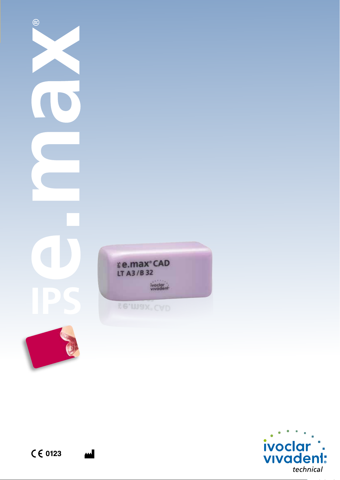
Preparation guidelines
Abutment in the
anterior region
Minimum thickness
Abutment in the
premolar region
Staining technique
Maximum pontic width in the anterior and premolar region
9 mm
Premolar region
to canine
11 mm
Anterior region
Bridges
Anterior region
mm
circular 1.2 1.5
incisal/occlusal 1.5 1.5
Premolar region
mm
Cut-back technique*
incisal/occlusal 0.8 1.0
Height ≥ Width
Width
*For maximum layer thickness of the IPS e.max Ceram veneer see IPS e.max CAD labside Instructions for Use.
IPS e.max CAD is processed by means of CAD/CAM systems from authorized partners,
the details of which can be found at www.ivoclarvivadent.com
Connector dimensions
circular 1.2 1.5
16 mm2
Basically, the following applies: Height ≥ Width
Page 3
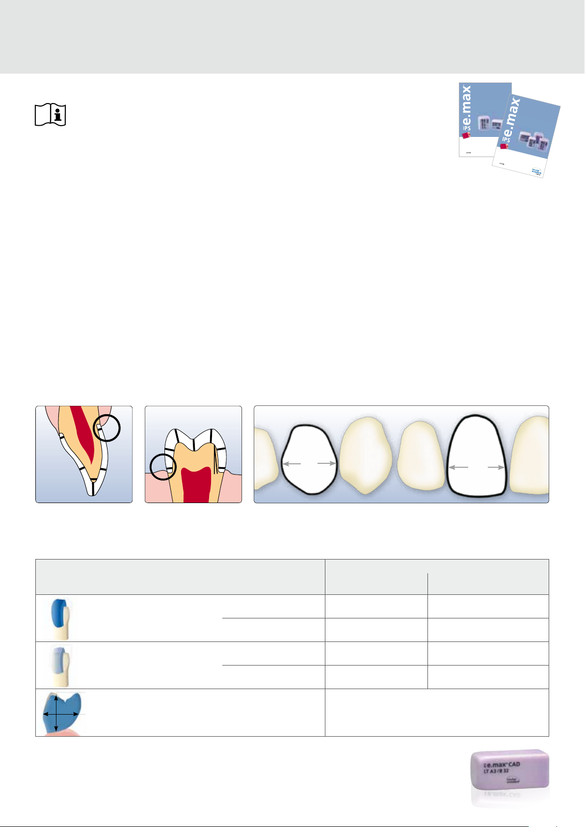
Staining technique using
IPS e.max CAD Crystall./Shades, Stains, Glaze
When using the staining technique,
apply individual characterizations and
glaze prior to combination firing
(crystallization and glaze firing). As a
result of the combined firing, this
technique is very efficient and leads
to a highly esthetic result quickly and
easily.
Bridge after CAD/CAM processing
Smooth out the attachment point and take
proximal contacts into account. Do not
inhale ceramic dust during finishing – use
exhaust air discharge and wear face mask.
Do not use diamond discs for finishing,
since this may result in predetermined
breaking points.
Finish interdental areas with fine-grit
diamonds (grit size 40–50 μm). Make sure
to observe the connector dimensions.
Fill the inside of the crowns of the previously
cleaned bridge with IPS Object Fix Putty
or Flow and press the appropriate
IPS e.max CAD Crystallization Pin
deeply into the IPS Object Fix material.
Apply IPS e.max CAD Crystall./Glaze
paste evenly to the blue restoration. Apply
the mixed IPS e.max CAD Crystall./
Shades and Stains into the unfired
IPS e.max CAD Crystall./Glaze paste.
Check occlusion, articulation and proximal
contacts.
Place the bridge on the IPS e.max CAD
Crystallization Tray immediately.
Place the IPS e.max CAD Crystallization Tray
with the glazed and stained restoration in
the furnace and conduct the combination
firing.
Surface-grind the outer surface, par-
ticularly the functional areas of the restoration, with a fine diamond to smooth out
the surface structure created by the
CAD/CAM process.
Smooth out displaced IPS Object Fix
Putty or Flow with a plastic spatula from
the margin towards the support pin so that
the pin is secured in the paste and the
crown wall is precisely supported.
Optional
If adjustments are required (shade, glaze,
contact points), conduct a separate
corrective firing cycle on the IPS e.max
CAD Crystallization Tray.
Use the largest possible IPS e.max CAD
Crystallization Pin for crystallization.
Clean off any possible residue adhering to
the outer surface of the restoration with a
brush moistened with water and then
dry.
Completed IPS e.max CAD LT bridge. To
remove any residue, immerse the restoration
in an ultrasonic cleaning bath or use a
steam cleaner.
Firing parameters
Furnaces
Stand-by
temperature
B [°C/°F]
Combination firing (crystallization/glaze firing)
Programat CS
(Program 1)
Programat
P300
P500
P700
403/757 6:00 90/162 820/1508 0:10 30/54 840/1544 7:00
Corrective firing
Programat CS
(Program 1)
Programat
P300
P500
P700
403/757 6:00 90/162 820/1508 0:10 30/54 840/1544 3:00
Note
Cooling after firing:
– Remove IPS e.max CAD objects from the furnace after completion of the firing cycle (wait for the acoustic signal of the furnace).
– Allow the objects to cool to room temperature in a place protected from draft.
– Do not touch the hot objects with metal tongs.
– Do not blast or quench the objects.
Closing time
S [min]
Heating rate
t
[°C/°F/min]
1
Firing
temperature
T
[°C/°F]
1
Holding time
H
[min]
1
Heating rate
t
[°C/°F/min]
2
Firing
temperature
T
[min]
2
Holding time
H
[min]
2
Vacuum 1
1
[°C/°F]
1
1
[°C/°F]
2
550/820
1022/1508
550/820
1022/1508
Vacuum 2
2
[°C/°F]
1
2
[°C/°F]
2
820/840
1508/1540
820/840
1508/1540
Long-term
cooling
L [°C/°F]
Cooling rate
t
[°C/°F/min]
l
700/1292 0
700/1292 0
Page 4
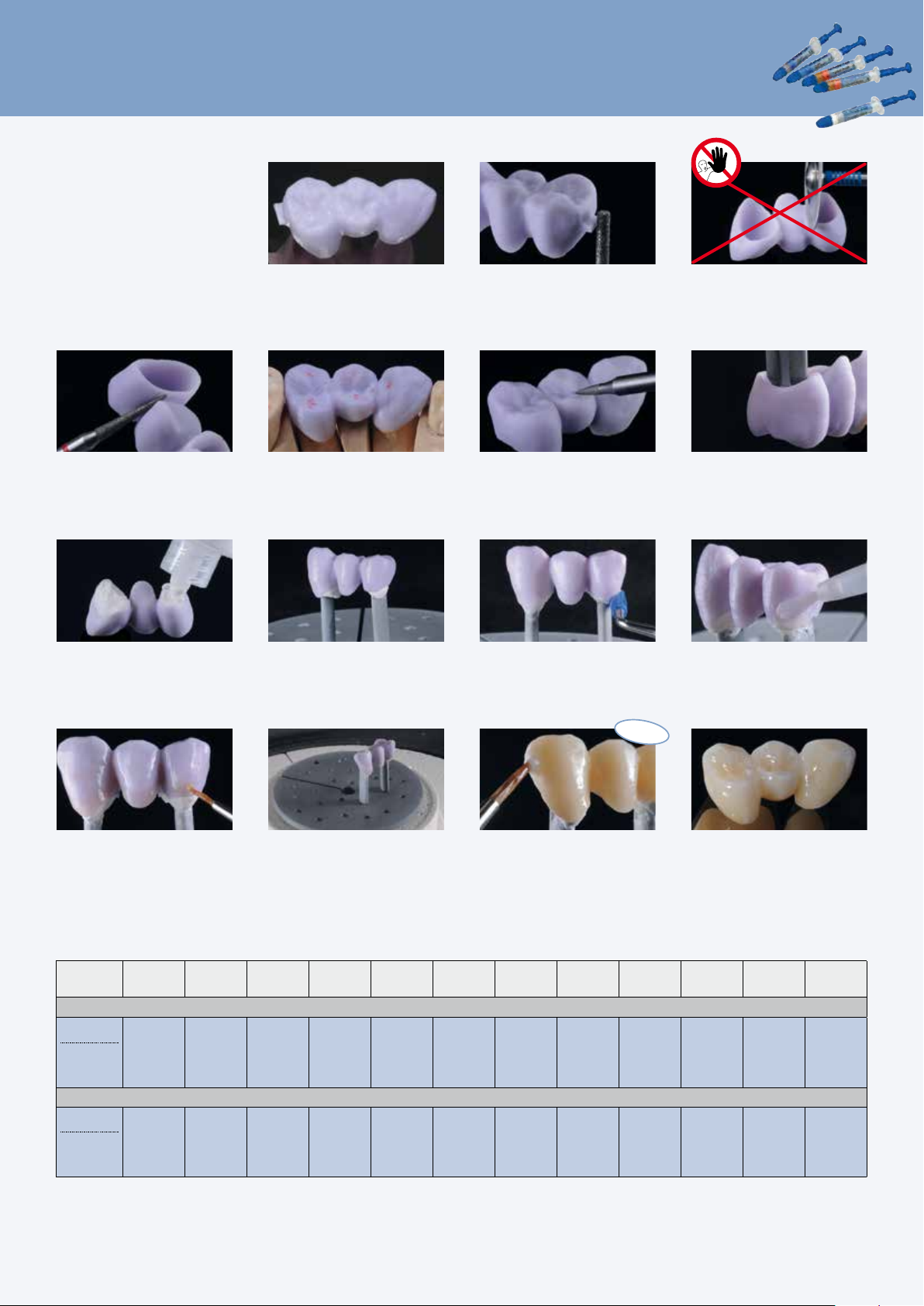
Cementation
The Cementation Navigation System, a new multimedia application from Ivoclar Vivadent, offers dentists prac-
tical orientation and guidance in the selection of the best luting material for each case.
www.cementation-navigation.com
CNS
Adhesive
cementation
Self-adhesive
cementation
Conventional
cementation
IPS e.max® CAD
Variolink® II,
SpeedCEM
®
Vivaglass® CEM
Multilink® Automix
Please observe the respective Instructions for Use.
Conditioning of the restoration
IPS® Ceramic Etching Gel contains hydrofluoric acid. Contact with skin, eyes and clothing must be prevented at all costs, since
the material is extremely toxic and corrosive. The etching gel is intended for extraoral use only and must not be applied
intraorally (inside the mouth).
®
Do not blast the restorations with Al
polishing beads.
2O3
or glass
Etch with 5% hydrofluoric acid (e.g. IPS
Etching Gel) for 20 seconds and rinse the acid off with
water.
Ceramic
Allow Monobond Plus to react for 60 s and then blow
dry with the air syringe. Silanization is not required for
conventional cementation procedures.
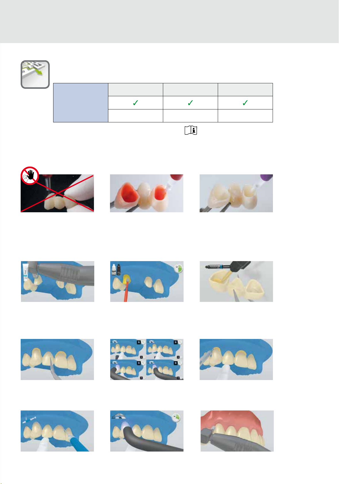
Cementation with e.g. Multilink Automix
Adhesive cementation
Ensure reliable isolation of the operating field,
preferably by placing a rubber dam (e.g. OptraDam
Clean preparation, rinse with water spray.
Subsequently, blow dry with oil- and moisture-free air.
Avoid overdrying.
Seat the restoration in place and fix/hold while
maintaining stable pressure.
Like all composite resins, Multilink Automix is subject
to oxygen inhibition. To avoid this, cover the restoration margins with glycerine gel/air block (e.g. Liquid
Strip) immediately after the removal of excess.
®
Apply the mixed Multilink Primer A/B with a micro-
).
brush to the entire bonding surface, starting with the
enamel, and scrub for 30 s. Take up fresh primer with
the micro-brush for each abutment. Disperse excess
amounts of Multilink Primer with a strong stream of
air until the mobile liquid film has disappeared.
Light-activate cement excess with a curing light (e.g.
®
) at a distance of max. 10 mm per quarter
Bluephase
surface (mesio-oral, disto-oral, mesio-buccal, distobuccal). Observe the indicated light intensity.
Subsequently, light-cure all cement lines again for
20 s (e.g. Bluephase, HIGH mode, approx.
1,200 mW/cm
the rubber dam.
2
). Rinse off glycerine gel and remove
Apply Multilink Automix directly into the conditioned
restoration.
The excess material has a gel-like consistency and
can be easily removed with a scaler.
Use finishing and polishing strips in the proximal
regions. Check occlusion and functional movements
and make adjustments if necessary. Polish restoration
margins with polishers (Astropol
®
) or discs.
Page 5
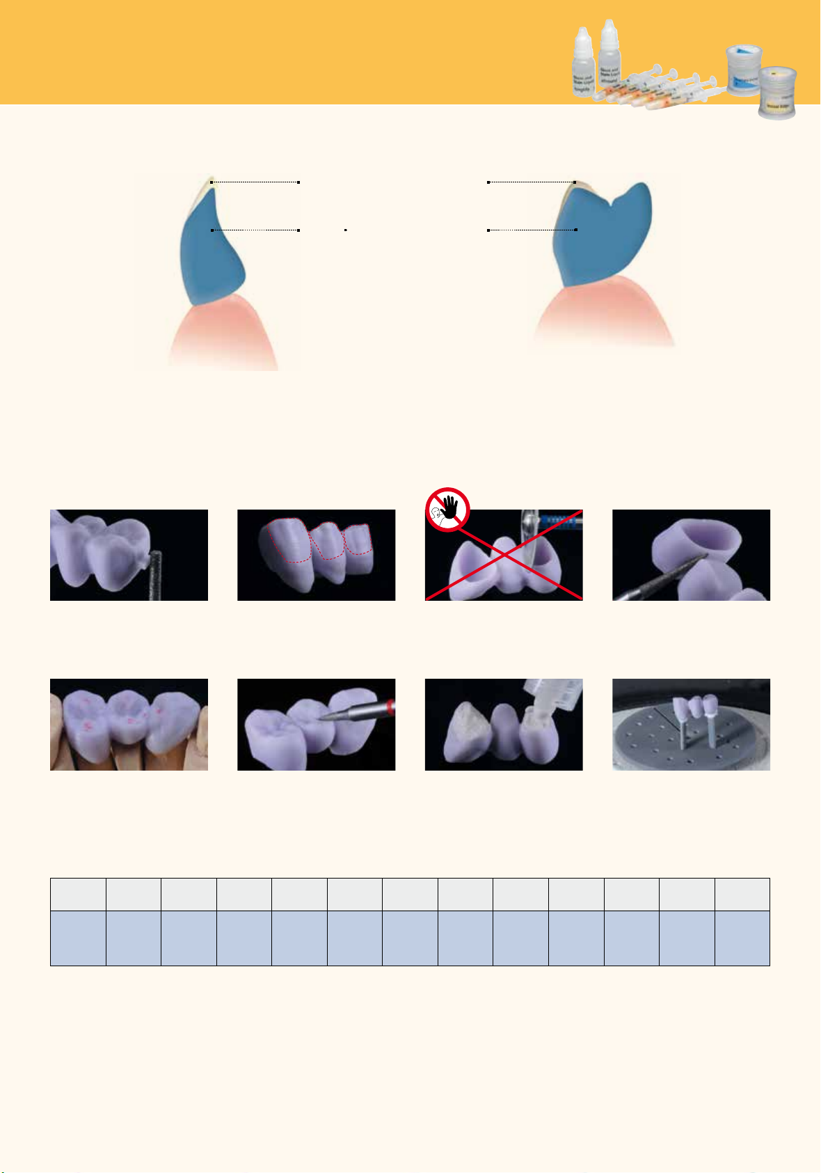
Cut-back technique using
IPS e.max Ceram
Design guidelines
IPS e.max Ceram veneer
Extension of IPS e.max CAD
Anterior region
Premolar region
When using the cut-back technique, IPS e.max Ceram Impulse and Incisal materials are applied in the incisal and/or occlusal area of the milled, reduced IPS e.max CAD pattern.
Make sure to observe the minimum dimensions during the cut-back process and refrain from designing extreme morphologies with undercuts for mamelons.
proximal contacts into account. Do not
Bridge after cut-back Smooth out the attachment point and take
inhale ceramic dust during finishing – use
exhaust air discharge and wear face mask.
Do not use diamond discs for finishing
as this may result in predetermined
breaking points.
Finish the interdental areas with fine-grit
diamonds (grit size 40–50 μm), making sure
to observe the connector dimensions
Check occlusion, articulation and proximal
contacts.
Surface-grind the outer surface,
particularly the functional areas of the
restoration with a fine diamond to smooth
out the surface structure created by the
CAD/CAM process.
Fill the inside of the crowns of the previously
cleaned bridge with IPS Object Fix Putty
or Flow and press the selected IPS e.max
CAD Crystallization Pin deeply into the
Object Fix material. Place the restoration on
Place the firing tray in the furnace and
conduct the crystallization firing cycle
with the respective parameters.
the IPS e.max CAD Crystallization Tray
Firing parameters
immediately.
Crystallization/Glaze
Furnace
Programat
P300
P500
P700
Stand-by
temperature
B [°C/°F]
403/757 6:00 90/162 820/1508 0:10 30/54 840/1544 7:00
Closing time
S [min]
Heating rate
t
[°C/°F/min]
1
Firing
temperature
T
[°C/°F]
1
Holding time
H
[min]
1
Heating rate
t
[°C/°F/min]
2
Firing
temperature
T
[°C/°F]
2
Holding time
H
[min]
2
Vacuum 1
1
[°C/°F]
1
1
[°C/°F]
2
550/820
1022/1508
Vacuum 2
2
[°C/°F]
1
2
[°C/°F]
2
820/840
1508/1540
Note
Cooling after firing
– Remove IPS e.max CAD objects from the furnace after completion of the firing cycle (wait for the acoustic signal of the furnace).
– Allow the objects to cool to room temperature in a place protected from draft.
– Do not touch the hot objects with metal tongs.
– Do not blast or quench the objects.
Long-term
cooling
L [°C/°F]
Cooling rate
t
[°C/°F/min]
l
700/1292 0
Page 6
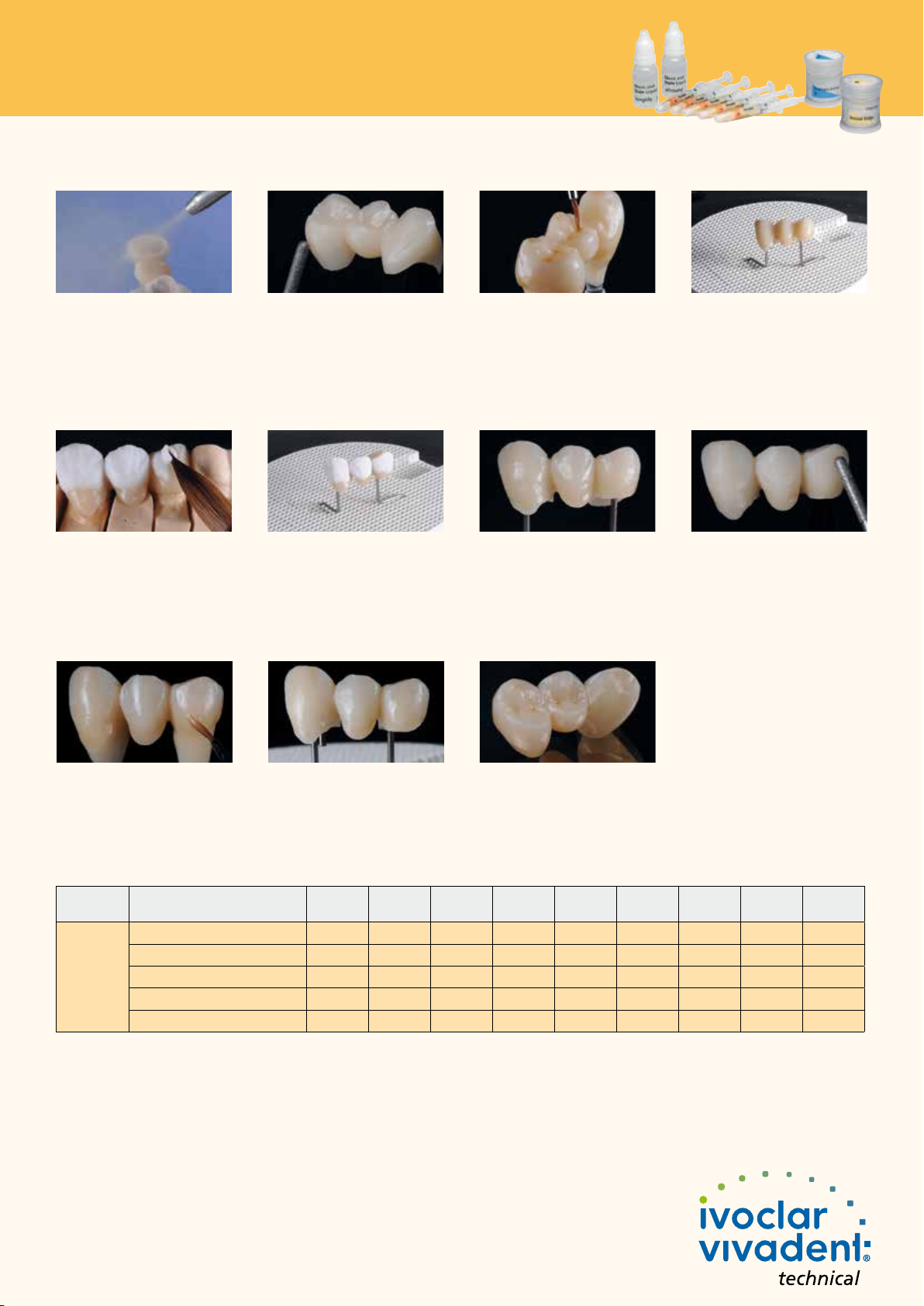
Cut-back technique using
IPS e.max Ceram
Wash firing (foundation)
Remove adhering IPS Object Fix residue by
immersing the restoration in an ultrasonic
cleaning bath or using a steam
cleaner. Do not blast the restoration with
or glass polishing beads.
Al
2O3
Incisal firing
Complete the anatomical shape using
IPS e.max Ceram Incisal und Transpa
materials. Do not veneer or separate
the connectors.
Stain and glaze firing
Finish the full-contour portion of the
IPS e.max CAD bridge using diamond
grinders and create a natural shape and
surface texture. (For details on the fabrication
of dies using IPS Natural Die Material see
"IPS e.max CAD labside").
Place the firing tray in the furnace and
conduct the incisal firing cycle with the
respective parameters.
Apply IPS e.max Ceram Glaze to the
entire bridge and apply individual characterizations using IPS e.max Ceram Shades
and Essences.
Bridge after incisal firing
The wash (foundation) must be fired before
the actual layering procedure is started.
Place the honey-combed firing tray in the
furnace and conduct the wash (founda-
tion) firing cycle with the respective
parameters.
Finish the veneered areas using diamond
grinders and create a natural shape and
surface texture.
Apply IPS e.max Ceram Glaze to the
entire bridge. If desired, apply individual
characterizations using IPS e.max Ceram
Shades and Essences.
Place the firing tray in the furnace and start
the stain/glaze firing cycle with the
respective parameters.
Completed IPS e.max CAD LT bridge
Remove any residue by immersing the
restoration in an ultrasonic cleaning bath or
using a steam cleaner.
Firing parameters
Furnaces IPS e.max Ceram on IPS e.max CAD
Programat
P300
P500
P700
Cut-back technique
Wash firing (foundation)
Incisal firing
Stain/glaze firing
Add-On with glaze firing
Add-On after glaze firing
Stand-by
temperature
B [°C/°F]
403/757 4:00 50/90 750/1382 1:00 450/842 749/1380 0 0
403/757 4:00 50/90 750/1382 1:00 450/842 749/1380 0 0
403/757 6:00 60/108 725/1337 1:00 450/842 724/1335 0 0
403/757 6:00 60/108 725/1337 1:00 450/842 724/1335 0 0
403/757 6:00 50/90 700/1292 1:00 450/842 699/1290 0 0
Note
Cooling after firing
– Remove IPS e.max CAD objects from the furnace after completion of the firing cycle (wait for the acoustic signal of the furnace).
– Allow the objects to cool to room temperature in a place protected from draft.
– Do not touch the hot objects with metal tongs.
– Do not blast or quench the objects.
Closing time
S [min]
Heating rate
t
[°C/°F/min]
1
Firing
temperature
T
[°C/°F]
1
Holding time
H
[min]
1
Vacuum 1
1
[°C/°F]
1
Vacuum 2
2
[°C/°F]
1
Long-term
cooling
L [°C/°F]
Cooling rate
t
[°C/°F/min]
l
 Loading...