

Page 1
CAD
Abutment Solutions
all ceramic
all you need
Instructions for Use
Page 2

Table of Contents
3 IPS e.max System
4 IPS e.max CAD
5 Product Information
Description of IPS e.max CAD Abutment Solutions
Material
Scientific data
CAD/CAM partners
9 Fabrication of Hybrid Abutments and Hybrid Abutment Crowns
Treatment/Fabrication process
Shade – tooth shade and abutment shade
Preparation for the CAD/CAM process
Layer thicknesses of the ceramic components
Block selection
CAD/CAM processing
Finishing
17 Optional: Clinical Try-In
Temporarily securing the ceramic structure on the Ti base
Clinical try-in
22 Completing the IPS e.max CAD Ceramic Structure
Polishing technique
Staining technique on the "blue restoration"
Staining technique on the "tooth-coloured restoration"
44 Crowns on IPS e.max CAD Hybrid Abutments
46 Permanent Cementation Ti Base / Ceramic Structure
52 Seating and Aftercare
Sterilization
Intraoral preparation
Seating the hybrid abutment and separate crown
Seating the hybrid abutment crown
Care notes – Implant care
60 General Information
Frequently asked questions
Material selection table
Crystallization and firing parameters
Clinical cases
2
Page 3
System
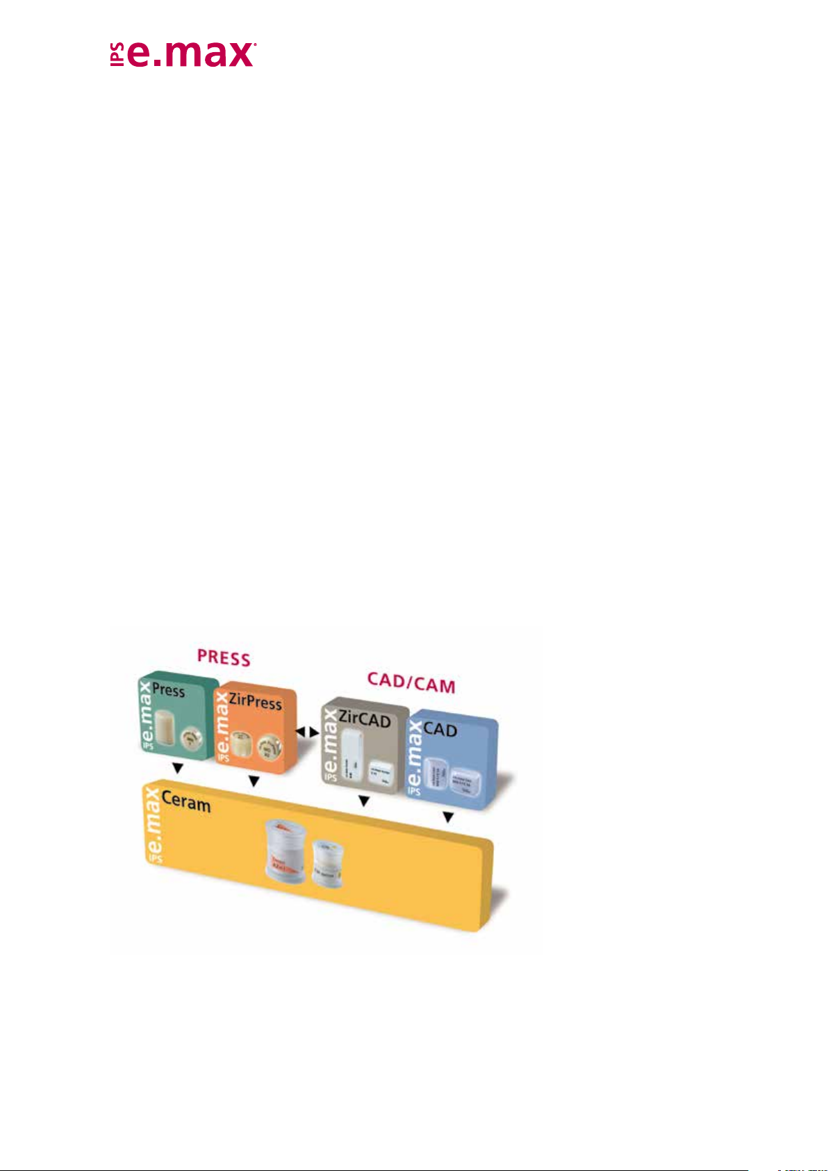
IPS e.max is an innovative all-ceramic system which covers the entire all-ceramic
indication range – from thin veneers to 14-unit bridges.
IPS e.max delivers high-strength and highly esthetic materials for the Press and the
CAD/CAM technologies. The system consists of innovative lithium disilicate glassceramics for smaller restorations and high-strength zirconium oxide for large-span
bridges.
The requirements and aims of every case differ. IPS e.max meets these requirements,
because due to the system components, you obtain exactly what you need.
– In the field of the Press technology, the highly esthetic IPS e.max Press lithium
disilicate glass-ceramic is available and with IPS e.max ZirPress a fluor
apaptite glass-ceramic ingot for the quick and efficient press-on technique on
zirconium oxide.
– For the CAD/CAM technology, depending on the case requirements, the innovative
lithium disilicate block IPS e.max CAD is used or the high-strength zirconium
oxide IPS e.max ZirCAD.
– The nano-fluorapatite layering ceramic IPS e.max Ceram, which is used to
characterize and/or veneer all IPS e.max components – glass or oxide ceramics –,
completes the IPS e.max System.
3
Page 4
CAD
tooth- and implant-retained
crowns and long-span bridges
(CAD-on).
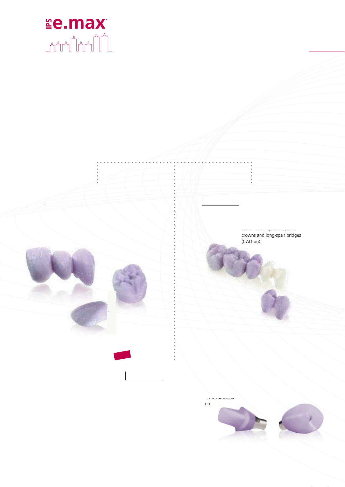
Three solutions for maximum flexibility
IPS e.max CAD Solutions
IPS e.max CAD stands for individuality. Depending on the indication, users may select
from three approaches: This ensures maximum flexibility in the digital work process.
IPS e.max CAD
Monolithic Solutions
Efficient fabrication of full-contour
restorations with high strength
(≥360 MPa) ranging from thin
veneers to three-unit bridges.
IPS e.max CAD
Veneering Solutions
Digitally fabricated high-strength
veneering structures for zirconium
oxide frameworks (ZrO2) – for
tooth- and implant-retained
crowns and long-span bridges
(CAD-on).
NEW
IPS e.max CAD
Abutment Solutions
Individual CAD/CAM-fabricated hybrid
restorations for implants – for single-
tooth restorations in the anterior
and posterior region.
4
Page 5
CAD Abutment Solutions
Product Information
Description
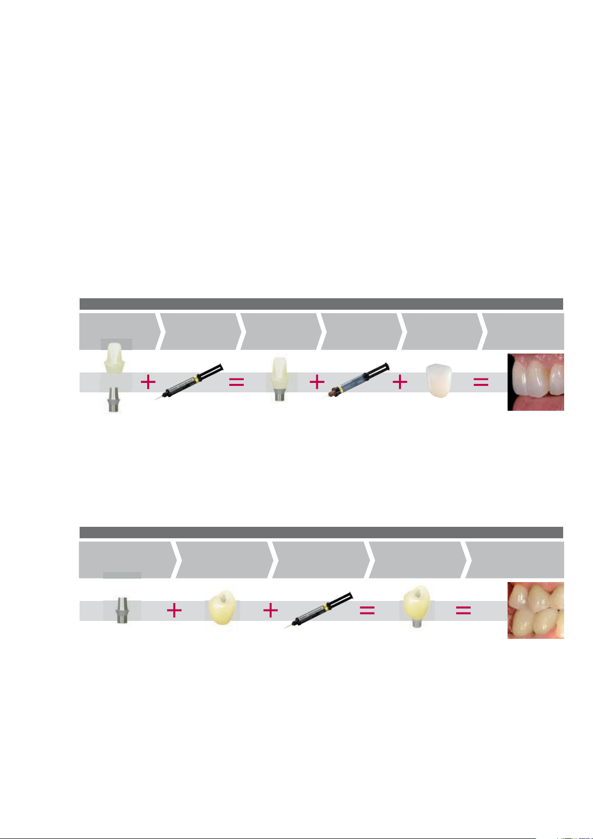
IPS e.max® CAD Abutment Solutions are CAD/CAM-fabricated, implant-supported hybrid
restorations for single teeth. These hybrid restorations are individually fabricated of lithium
disilicate glass-ceramics (LS2) and cemented onto a titanium base (Ti base).
Two different approaches are available:
– IPS e.max CAD hybrid abutment and separate IPS e.max CAD crown
– IPS e.max CAD hybrid abutment crown
Both solutions show outstanding function, efficiency and esthetics. The durable bond to the Ti base is
achieved by means of the self-curing Multilink® Hybrid Abutment luting composite.
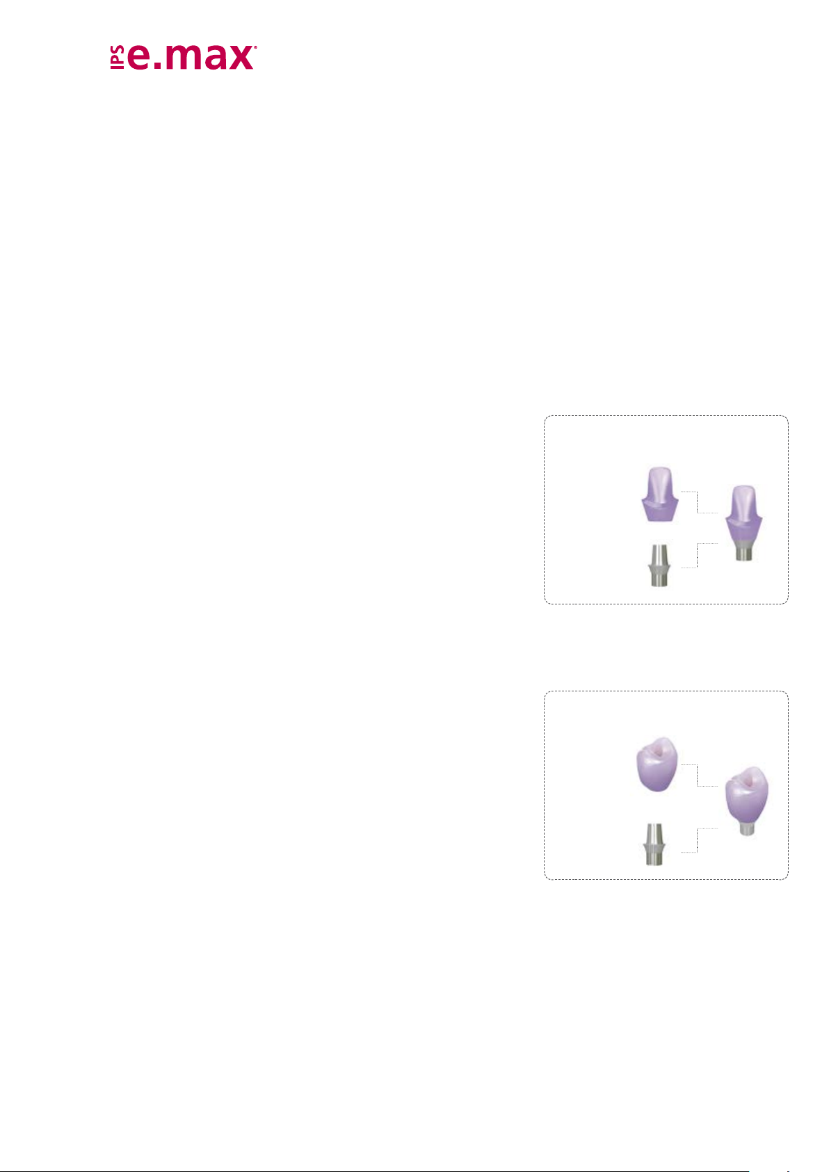
Hybrid abutment
The hybrid abutment is an individually milled LS
emergence profile and esthetic properties of this abutment can be ideally adjusted to
the clinical situation.
Given the lifelike appearance of LS2 glass-ceramics, the esthetic possibilities are virtually
limitless, particularly in the anterior region. Due to the individual characterization, a
lifelike appearance is achieved near the root and the transition area to the crown. With
the preparation margin of the crown located on the gingival level, the geometry of the
hybrid abutments allows for an easy integration of the restoration. Excess cementation
material is therefore easily removed.
The milled and crystallized LS2 ceramic structure is extraorally luted to a Ti base with
Multilink Hybrid Abutment, then screwed into place in the oral cavity and finally provided with a permanent IPS e.max CAD crown. Given the convenient fabrication of the
hybrid abutment, the process is time-saving and flexible.
abutment which is luted to the Ti base. The shape,
2
IPS e.max CAD
(Ceramic structure)
MO
Ti base
IPS e.max CAD
Hybrid Abutment
Hybrid abutment crown
Hybrid abutment crowns are characterized by combining abutment and monolithic
crown in one piece. This is an efficient two-in-one solution made of lithium disilicate
(LS
), which is directly luted to a Ti base.
2
LS2 glass-ceramics provide for strength, durability and efficiency, particularly in the
posterior region. Moreover, the material offers well-known esthetic properties, allowing
restorations to be simply characterized with IPS e.max Ceram stains.
The monolithically milled hybrid abutment crown is reliably and extraorally luted to the
Ti base by means of Multilink Hyrid Abutment. Then, the restoration is screwed onto
the implant – in one piece. Subsequently, the screw access channel is sealed with a
composite material (e.g. Tetric EvoCeram®). If required, the screw can be accessed at
any time, which affords the dental team clinical flexibility.
IPS e.max CAD hybrid abutment crowns are a new, economically attractive alternative to conventional
implant-supported restorations, particularly for the posterior region, where strength, durability and
convenient clinical handling matter.
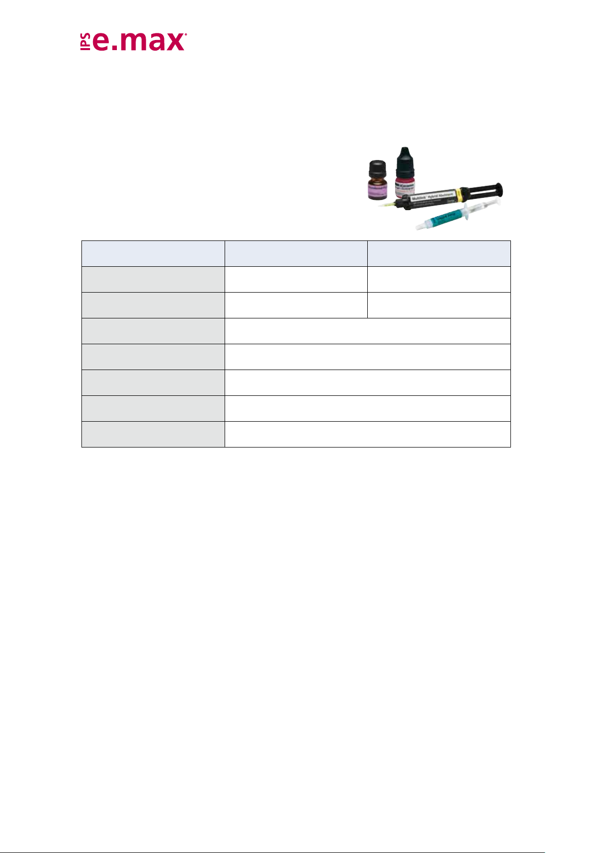
Ideally coordinated – Multilink
The self-curing luting composite Multilink Hybrid Abutment in conjunction with Monobond
for the permanent cementation of ceramic structures made of lithium disilicate glass-ceramic (LS2) or
zirconium oxide (ZrO2) onto bases (e.g. abutment or adhesive base) of titanium/titanium alloy.
This allows
– reliable adhesion due to high bonding values
– optimum esthetics due to two available degrees of opacity
– easy handling due to the convenient Automix syringe
®
Hybrid Abutment
IPS e.max CAD
LT
(Ceramic structure)
Ti base
®
Plus is used
IPS e.max CAD
Hybrid Abutment
Crown
5
Page 6
Material
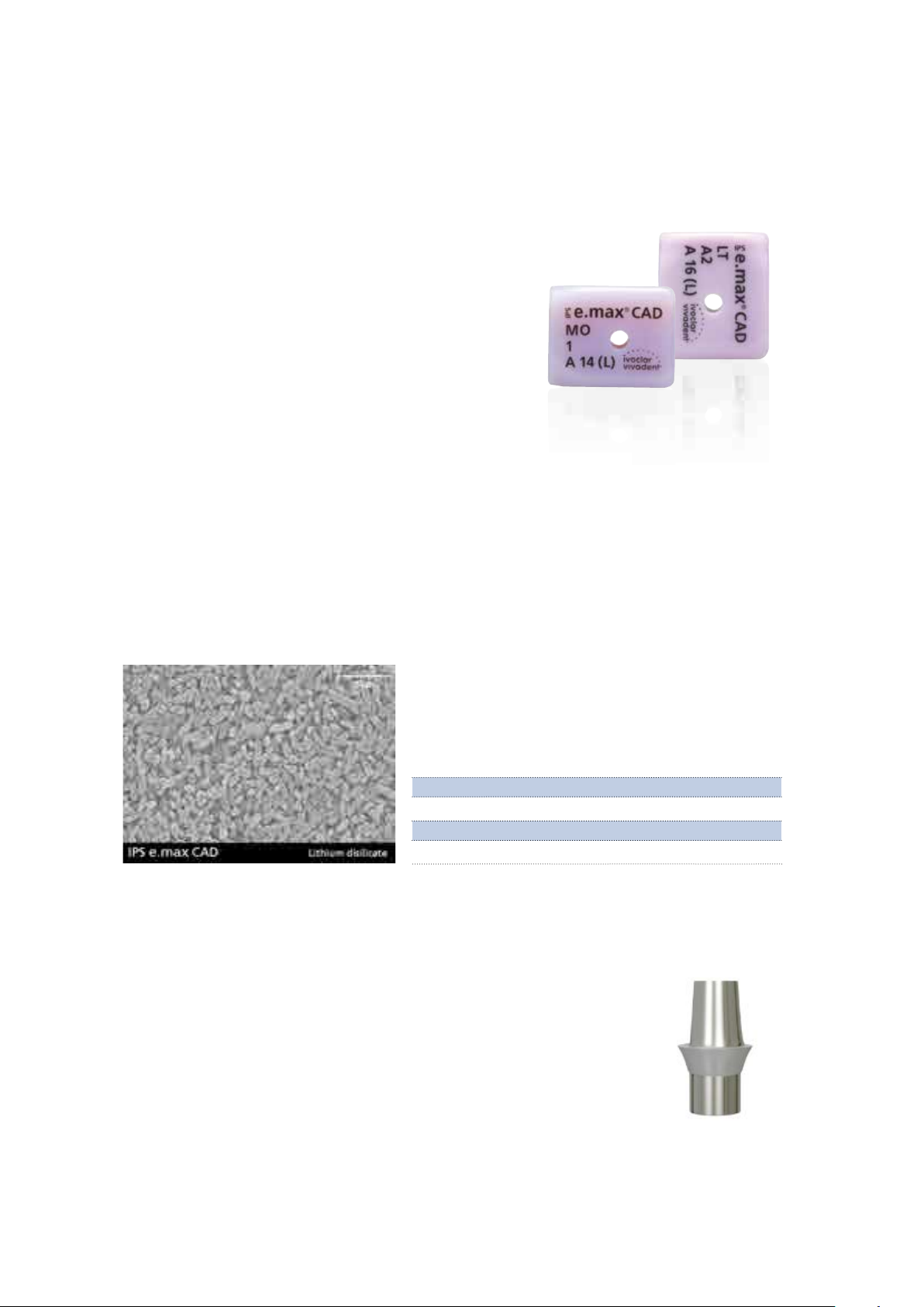
IPS e.max CAD
IPS e.max CAD is a lithium disilicate glass-ceramic block for the CAD/
CAM technology. It is fabricated using an innovative process which
provides an impressive homogeneity of the material. The block can
be processed very easily in a CAD/CAM unit in this crystalline intermediate stage. The typical and striking colour of IPS e.max CAD
ranges from whitish to blue and bluish-grey. This shade is a result of
the composition and the microstructure of the glass-ceramic. The
strength of the material in this processable intermediate phase is
≥ 130 MPa. After the IPS e.max CAD blocks are milled, the restoration is crystallized in an Ivoclar Vivadent ceramic furnace (e.g.
Programat
easy-to-conduct crystallization process neither causes any major
shrinkage, nor are any complicated infiltration processes required.
The crystallization process leads to a change in the microstructure in
the IPS e.max CAD material, during which lithium disilicate crystals
grow. The densification of 0.2% is accounted for in the CAD software and taken into account upon milling. The final physical properties, such as the strength of ≥ 360 MPa and the corresponding optical properties, are achieved through the transformation of the microstructure.
®
P500). Unlike with some other CAD/CAM ceramics, the
CTE (100–500°C) [10-6/K] 10.5 ± 0.5
Flexural strength (biaxial) [MPa] ≥ 360 according to ISO 6872
Fracture toughness [MPa m
0.5
Chem. solubility [µg/cm2] ≤ 50 according to ISO 6872
Ti base
Ti bases are used for the fabrication of IPS e.max CAD Abutment Solutions. The suitable Ti bases are selected in accordance with the CAD/CAM system used. Please
observe the instructions for use and processing of the manufacturer of the Ti bases
used.
More information about the authorized CAD/CAM systems is available on the Internet
from www.ivoclarvivadent.com.
] ≥ 2.0 according to ISO 6872
6
Page 7

Uses
Indications
– Hybrid abutments for anterior and posterior single-tooth restora-
tions
– Hybrid abutment crowns for anterior and posterior restorations
Contraindications
– Failure to observe the requirements stipulated by the implant man-
ufacturer for using the selected implant type (diameter and length
of the implant must be approved for the respective position in the
jaw by the implant manufacturer)
– Failure to observe the permissible maximum and minimum ceramic
wall thicknesses
– Parafunctions (e.g. bruxism)
– Use of a luting composite other than Multilink
®
Hybrid Abutment
to lute IPS e.max CAD to the Ti base
– Intraoral adhesion of the ceramic structures to the Ti base
– Temporary cementation of the crown on the hybrid abutment
– All uses not stated as indications are contraindicated.
Important processing restrictions
– Do not mill the blocks with non-compatible CAD/CAM systems.
– If hybrid abutment crowns are fabricated, the opening of the
screw channel must not be located in the area of contact points. If
this is not possible, a hybrid abutment with a separate crown
should be preferred.
– Combination with materials other than IPS e.max Ceram or
IPS e.max CAD Crystall./ materials
– Crystallization in a non-recommended ceramic furnace
– Crystallization in a non-calibrated ceramic furnace
– Crystallization in a high-temperature furnace (e.g. Programat
®
S1)
– Crystallization with deviating firing parameters
– Failure to observe the manufacturer's instructions regarding the
processing of the Ti base.
Composition
– IPS e.max CAD blocks
Components: SiO
, Li2O, K2O, MgO, Al2O3, P2O5 and other oxides
2
– IPS e.max CAD Crystall./Glaze, Shades and Stains
Components: Oxide, glycols
– IPS e.max CAD Crystall./Glaze Liquid
Components: Butandiol
– IPS e.max CAD Crystall./Add-On
Components: Oxides
– IPS e.max CAD Crystall./Add-On Liquid
Components: Water, propylene glycol, butandiol and chloride
– IPS Object Fix Putty/Flow
Components: Oxides, water, thickening agent
– IPS Natural Die Material
Components: Polymethacrylate, paraffin oil, SiO2 and copolymer
– IPS Natural Die Material Separator
Components: Wax dissolved in hexane
– Virtual Extra Light Body Fast Set
Components: Vinyl polysiloxane, methyl hydrogen polysiloxane,
organic platinum complex, silicate and food colouring
– Multilink Hybrid Abutment
Components: Dimethacrylate, HEMA, as well as fillers (barium
glass, ytterbium trifluoride, spheroid mixed oxide and titanium
dioxide).
– Monobond Plus
Components: Alcohol solution of silane methacrylate, phosphoric
acid methacrylate and sulphide methacrylate
– IPS Ceramic Etching Gel
Components: Hydrofluoric acid (approx. 5%)
Side effects
If the patient is known to be allergic to any of the components,
IPS e.max CAD and the other materials necessary for the fabrication
should not be used.
Warning
– Do not inhale ceramic dust during finishing. Use exhaust air
discharge and mouth protection.
– IPS Ceramic Etching Gel contains hydrofluoric acid. Contact with
skin, eyes and clothing must be prevented at all costs, since the
material is extremely toxic and corrosive. The etching gel is
intended for extraoral use only and must not be applied intraorally
(inside the mouth).
7
Page 8
Scientific data
all ceramic
all you need
SCIENTIFIC REPORT
Further scientific data (i.e. strength, wear, biocompatibility) are contained in the Scientific
Documentation IPS e.max CAD.
The IPS e.max Scientific Report contains all studies (in vitro, in vivo) on IPS e.max CAD and the
IPS e.max system.
For further information about all-ceramics in general, please refer to the Ivoclar Vivadent Report
No. 16.
Scientific Documentation
SCIENTIFIC REPORT
all ceramic
all you need
Vol. 01 / 2001 – 2011
english
CAD/CAM partners
IPS e.max CAD has to be processed with an authorized CAD/CAM system. For questions regarding the
different systems, please contact the respective cooperation partners.
More information is available on the Internet from www.ivoclarvivadent.com.
8
Page 9
CAD Abutment Solutions
Ceramic
structure
(Abutment)
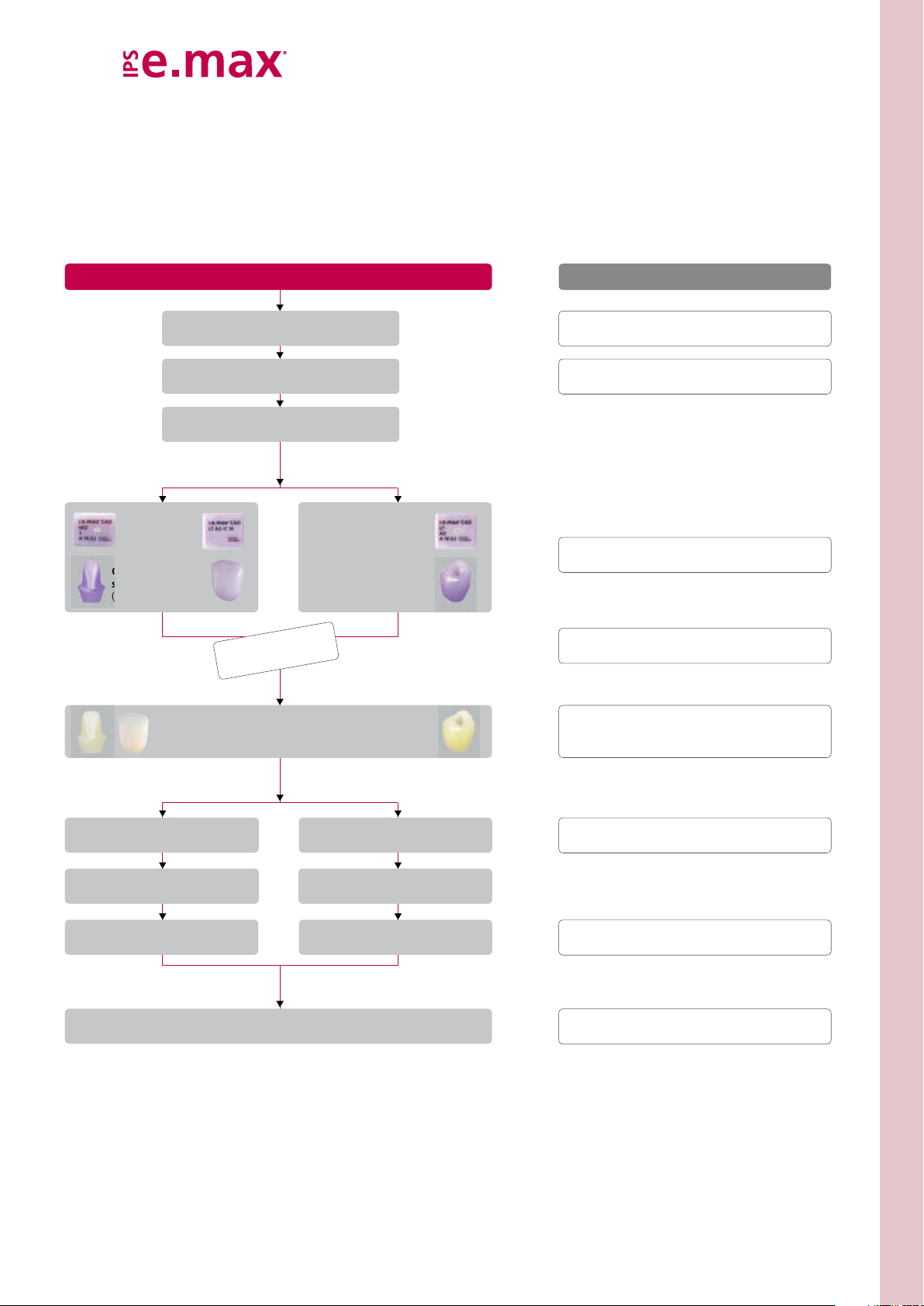
Fabrication of IPS e.max CAD hybrid abutment and
hybrid abutment crown
Working Steps
Implantation, healing phase,
gingiva shaping
Shade determination,
impression-taking
CAD design
CAM CAM
Ceramic
structure
(Abutment)
Crown
Optional
Clinical try-in
Crystallization/Characterization/Glaze
firing
Ceramic structure
(Abutment crown)
Ivoclar Vivadent Products
Cervitec® Plus, Cervitec® Liquid,
Virtual
Telio® System
OptraGate
IPS e.max
®
Extra Light Body Fast Set
IPS e.max
IPS e.max® Ceram
Programat® furnaces
®
, Virtual®
®
CAD
®
CAD Crystall./ ...
Cementing
Ti base / ceramic structure
Screwing in the
hybrid abutment
Cementing
the crown
Final check
Implant care
Cementing
Ti base / ceramic structure
Screwing in the
hybrid abutment crown
Sealing
the screw channel
®
IPS Ceramic Etching Gel, Monobond
Multilink® Hybrid Abutment, Liquid Strip
SpeedCEM®, Bluephase®, Tetric EvoCeram®
OptraFine,
Implant Care
Plus,
Clinical Working Steps | Layer Thicknesses | Block Selection | Finishing – Fabrication Hybrid Abutment and Hybrid Abutment Crown
9
Page 10
Shade – tooth shade and abutment shade
Optimum integration in the oral cavity of the patient is the prerequisite for a true-to-nature all-ceramic restoration. To
achieve this, the following guidelines and notes must be observed.
With IPS e.max CAD Abutment Solutions, you can imitate not only the clinical crown of a natural tooth, but also a part of
the root. This allows you to achieve highly esthetic implant-supported restorations which retain their lifelike appearance
also in the case of gingiva recession.
For IPS e.max CAD hybrid abutment and the separate crown, the desired tooth shade results from
– the shade of the IPS e.max CAD hybrid abutment (IPS e.max CAD MO ceramic structure, Multilink Hybrid Abutment)
– the shade of the luting material for intraoral cementation of the crown on the IPS e.max CAD hybrid abutment
(e.g. SpeedCEM)
− the shade of the IPS e.max CAD LT crown.
Hybrid abutment and separate crown
Colour
IPS e.max CAD MO
ceramic structure
Ti base
Shade
Multilink Hybrid
Abutment
(extraoral cementation)
Shade
IPS e.max CAD
hybrid abutment
Shade
luting material
(intraoral cementation)
Shade
IPS e.max CAD LT
crown
Desired
tooth shade
For the IPS e.max CAD hybrid abutment crown, the desired tooth shade results from
− the shade of the IPS e.max CAD LT ceramic structure
– the shade of Multilink Hybrid Abutment.
Hybrid abutment crown
Ti base Shade
IPS e.max CAD LT
ceramic structure
Shade
Multilink
Hybrid Abutment
(extraoral cementation)
Shade
hybrid abutment crown
Desired
tooth shade
10
Page 11

Preparation for the CAD/CAM process
Scanning
For the fabrication of IPS e.max CAD Abutment Solutions and depending on the CAD/CAM system used,
the clinical situation is digitalized either by a direct intraoral scan or an indirect model scan. For notes
regarding the scan, please observe the manufacturer's instructions for use of the CAD/CAM system.
Selecting a Ti base
The required Ti base is selected depending on the inserted implant and the CAD/CAM system used.
Clinical Working Steps | Layer Thicknesses | Block Selection | Finishing – Fabrication Hybrid Abutment and Hybrid Abutment Crown
11
Page 12
Layer thicknesses of the ceramic components
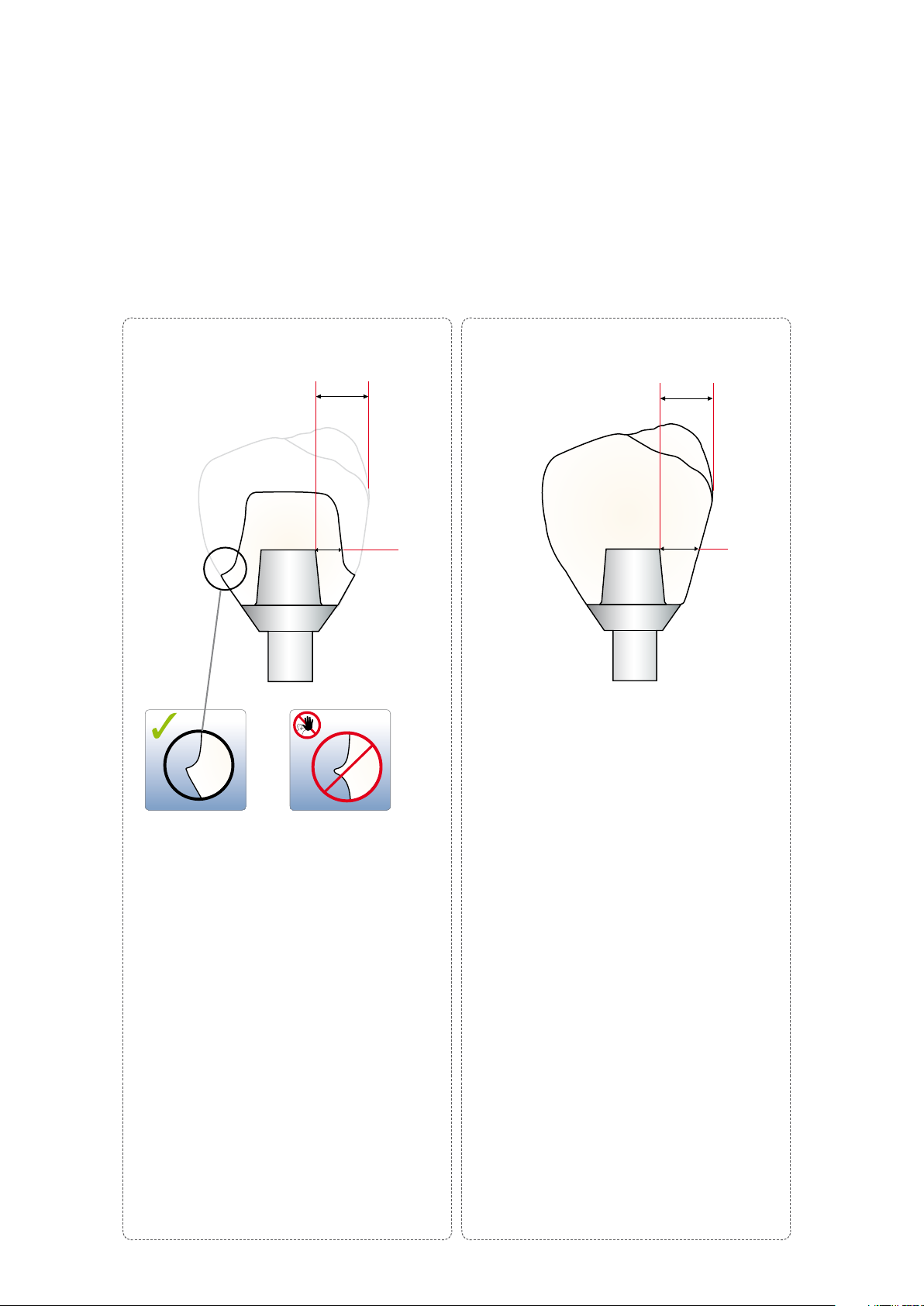
Observing the geometry requirements of the IPS e.max CAD ceramic structures is the key to success for a durable restoration.
The more attention is given to the design, the better the final results and the clinical success will turn out to be.
The following basic guidelines have to be observed:
Hybrid abutment crownHybrid abutment
Width crown B
Crown
Width
hybrid abutment crown B
HAK
Wall thickness W
HA
– The wall thickness WHA, must be at least 0.5 mm.
– The hybrid abutment should be designed in a
similar way as a prepared natural tooth:
– Circular epi-/supragingival shoulder with rounded
inner edges or a chamfer.
– In order for the crown to be cemented to the
hybrid abutment using a conventional/selfadhesive cementation protocol, retentive surfaces
and a sufficient "preparation height" must be
observed.
– Create an emergence profile with a right angle at
the transition to the crown (see picture).
– The crown width B
is limited to 6.0 mm from
Crown
the axial height of contour to the screw channel of
the hybrid abutment.
– The notes of the implant manufacturer must be
observed regarding the maximum height of the
hybrid abutment and separate crown.
Wall thickness W
– The wall thickness of hybrid abutment crown
must be larger than 1.5 mm for the entire
W
HAK
circumference.
– The opening of the screw channel must not be
located in the area of contact points. If this is not
possible, a hybrid abutment with a separate crown
would be preferred.
– The width of the hybrid abutment crown B
HAK
limited to 6.0 mm from the axial height of contour
to the screw channel.
– The notes of the implant manufacturer must be
observed regarding the maximum height of the
hybrid abutment crown.
HAK
is
12
Page 13
Block selection
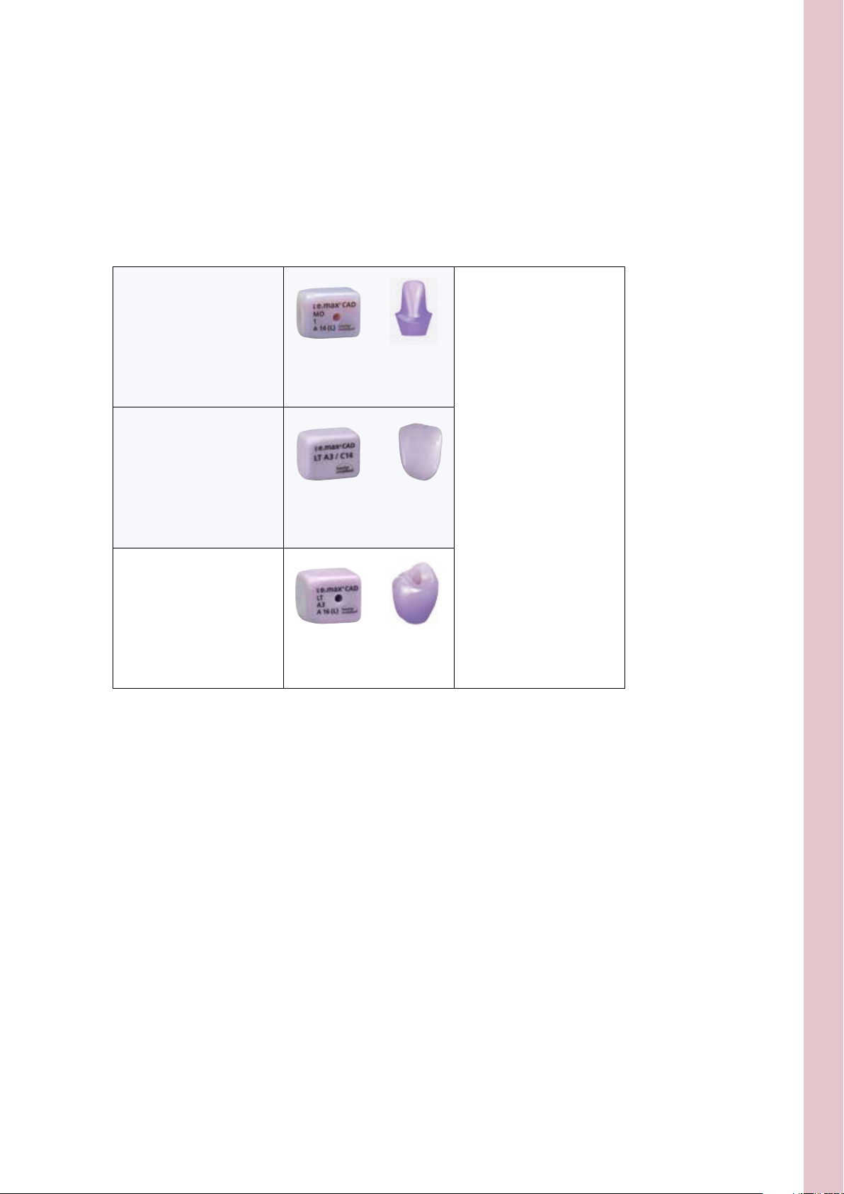
An IPS e.max CAD MO or LT block is selected depending on the indication.
When using a Ti base from Sirona, the dimensions of the interface to the Ti Base (S or L) have to be
observed.
IPS e.max CAD
hybrid abutment
IPS e.max CAD crown
(on IPS e.max CAD hybrid abutment)
IPS e.max CAD
hybrid abutment crown
IPS e.max CAD MO
(Medium Opacity)
IPS e.max CAD LT
(Low Translucency)
IPS e.max CAD LT
(Low Translucency)
Please refer to the table on
page 62 for the selection of
the block shade for the desired
tooth shade.
Clinical Working Steps | Layer Thicknesses | Block Selection | Finishing – Fabrication Hybrid Abutment and Hybrid Abutment Crown
CAD/CAM processing
As densification of about 0.2% occurs in IPS e.max CAD during crystallization, this factor has been taken
into account in the respective software of the tested CAD/CAM system. Consequently, the milled
IPS e.max CAD restorations demonstrate a high accuracy of fit after crystallization. The fabrication steps
are described in the directions for use and user manuals of the different CAD/CAM systems. The
instructions of the manufacturers must be followed.
13
Page 14
Finishing
It is of critical importance to use the correct grinding instruments for finishing and adjusting the IPS e.max CAD ceramic
structure. If unsuitable grinding instruments are used, chipping of the edges and local overheating may occur (please
observe the Ivoclar Vivadent Flow Chart "Recommended grinding tools for PS e.max glass-ceramics").
Basic notes regarding the finishing of IPS e.max CAD
– Carry out adjustments by grinding of IPS e.max CAD restorations while they are still in their pre-crystallized (blue) state, if
possible.
– Only use suitable grinding instruments, low speed and light pressure to prevent delamination and chipping at the
margins in particular. Overheating of the glass-ceramic must be avoided.
– During finishing, make sure that the minimum layer thicknesses are observed.
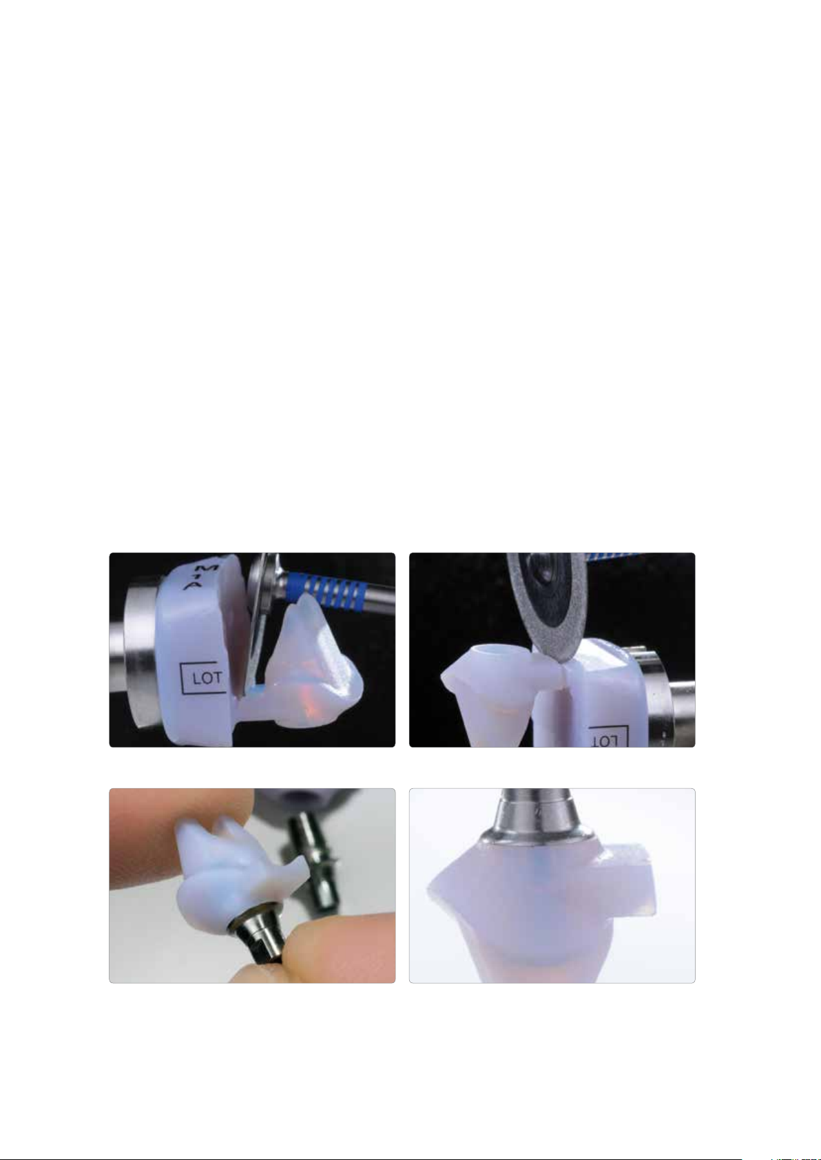
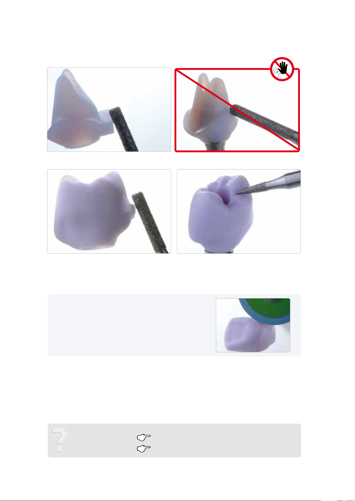
– Cut the ceramic structure from the block using a diamond separating disc. Slightly scratch the attachment area at the
incisal side of the abutment and separate the attachment point from the basal.
Checking the fit of the ceramic structure on the Ti base
– Carefully place the ceramic structure on the Ti base and check the fit. Observe the position of the rotation lock.
The incisal side of the attachment point is scratched with a diamond separating disc.
The ceramic structure is carefully placed on the Ti base to check the fit.
The attachment is cut from the basal using a diamond separating disc.
Optimum fit of the ceramic structure on the Ti base
14
Page 15
Finishing
Important!
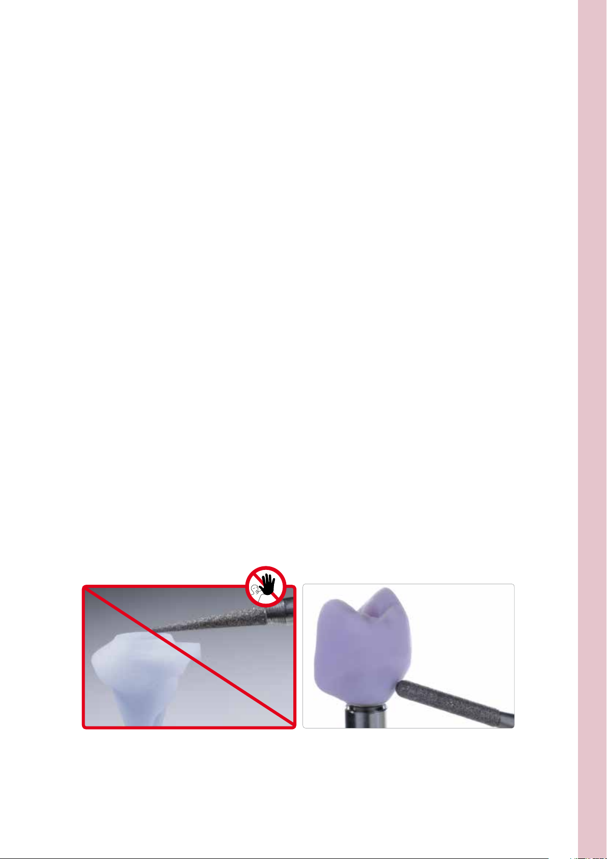
– Do not finish the shoulder of the ceramic structure to prevent negatively affecting the Ti base.
– Finish the emergence profile if required taking the fit to the gingiva and the minimum thickness (0.5mm) into
account.
Finishing the outer surface of the ceramic structure (hybrid abutment)
– Smooth out the attachment point to the block with fine diamond grinding instruments taking the shape of the
emergence profile and the crown margin into account.
– Do not perform any individual shape adjustments, as this will negatively affect the fit of the crown on the hybrid
abutment. Note regarding the crown: If there are any inaccuracies of fit to the hybrid abutment, adjust the crown
by grinding.
Finishing the outer surface of the ceramic structure (hybrid abutment crown)
– Smooth out the attachment point to the block with fine diamond grinding instruments taking the shape of the
emergence profile and the proximal contacts into account.
– Surface-grind the entire occlusal surface with a fine diamond to smooth out the surface structure created by the
CAD/CAM procedure.
– Check the proximal and occlusal contacts.
– Design surface textures.
– Clean the ceramic structures with ultrasound in a water bath or blast with the steam jet before further processing.
– Make sure to thoroughly remove any residue of the milling additive of the CAD/CAM milling unit. Residue of the milling
additive remaining on the surface may result in bonding problems and discolouration.
– Do not blast ceramic structures with Al
or glass polishing beads!
2O3
The shoulder of the ceramic structure must not be finished to prevent negatively
affecting the Ti base.
Care should be taken when finishing the emergence profile to prevent affecting
the fit to the gingiva.
Clinical working steps | layer thicknesses | block selection | finishing – Fabrication hybrid abutment and hybrid abutment crown
15
Page 16
The attachment point to the block is smoothed out taking the shape of the emergence
profile and the crown margin into account.
Individual shape adjustments must not be performed, as this negatively affects the fit
of the crown on the hybrid abutment.
The attachment point to the block is smoothed out taking the shape of the emergence
profile and the crown margin into account.
The surface of the ceramic structure is ground with a fine diamond to smooth out the
Tip
Place the crown on the ceramic structure to finish the crown margins. In this
way, a smooth transition between the crown and hybrid abutment can be
achieved.
next working step … Optional: Clinical try-in page 17
surface structure created by the CAD/CAM procedure.
Completing the IPS e.max CAD ceramic structure page 22
16
Page 17
CAD Abutment Solutions
Optional: Clinical try-in
A clinical try-in to check the accuracy of fit can be conducted prior to further processing. Clinical try-in may also take place
at a later stage, i.e. with the crystallized, tooth-coloured IPS e.max CAD ceramic structure.
Provisional securing of the ceramic structure on the Ti base
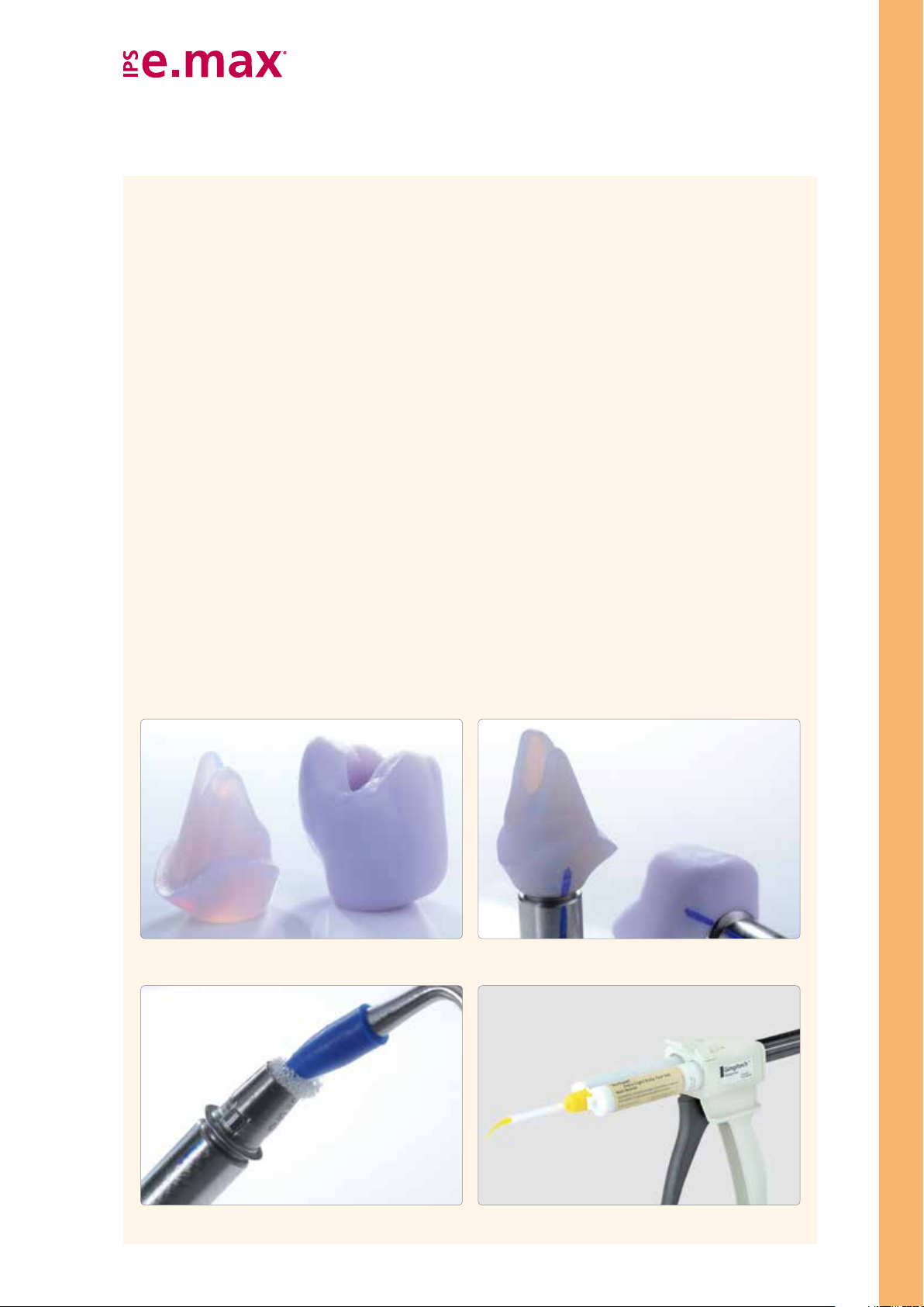
To facilitate the intraoral handling, the components are temporarily attached to one another with silicone material, e.g.
Virtual Extra Light Body Fast Set.
The following procedure should be observed in the temporary attachment of the components:
– Clean the untreated Ti base and the ceramic structure with steam and subsequently dry with blown air.
– Place the ceramic structure on the Ti base (which is screwed on the model analog) and mark the relative position of
the components with a waterproof pen. This step makes it easier to attain the correct position when the parts are
temporarily assembled.
– Seal the screw channel with a foam pellet.
– Insert the Virtual cartridge in the dispenser and remove the protective cap.
– Screw on the mixing tip and attach the Oral Tip to the mixing tip.
– Apply Virtual Extra Light Body Fast Set to the Ti base and directly into the ceramic structure.
– Introduce the Ti base into the ceramic structure. The alignment of the two component must be checked
(rotation lock/marking).
– Hold the components firmly in the correct position for 2:30 minutes until Virtual Extra Light Body Fast Set has set.
– Carefully remove any excess that has been displaced with a suitable instrument, e.g. a scalpel.
Optional – Clinical Try-In
Cleaned, untreated ceramic structures
The screw channel is sealed with a foam pellet.
The ceramic structure is placed on the Ti base and the relative position is marked.
The Virtual cartridge is inserted in the dispenser. The mixing tip is screwed on and the
17
Oral Tip is attached.
Page 18
Virtual Extra Light Body Fast Set is applied to the Ti base ...
... and directly on the ceramic structure.
The Ti base is introduced into the ceramic structure. In doing so, the alignment of the
two components is checked (rotation lock/marking). The components are firmly held in
place for approx. 2:30 minutes until the Virtual Extra Light Body Fast Set has set.
Excess Virtual Extra Light Body Fast Set material is removed from the screw channel
with an instrument.
Excess Virtual Extra Light Body Fast Set is removed from the screw channel
Prepared hybrid abutment or hybrid abutment crown
with an instrument, e.g. a scalpel.
18
Page 19

Clinical try-in
Hybrid abutment and dedicated crown
Important note: Any intraoral inspection of the occlusion/articulation and necessary grinding adjustments may only be
carried out if the components have been attached to one another with Virtual Extra Light Body Fast Set. Virtual has a
cushioning effect during the try-in procedure, in particular, if any grinding adjustments have to be made. Therefore, it
prevents chipping in the transition area between the hybrid abutment and the crown.
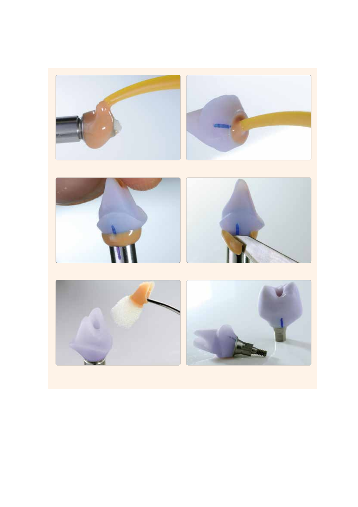
The following procedure should be observed during the clinical try-in:
– The prepared hybrid abutment (provisionally secured in place) and the clean corresponding crown are laid out.
– Remove the provisional restoration.
– Screw the hybrid abutment in manually with the dedicated screw.
– Check the geometry of the hybrid abutment (e.g. fit gingival anaemia) in relation to the gingival margin.
– If desired, the screw channel on the hybrid abutment can be sealed with a foam pellet.
– Tip: Isolate the inner aspect of the crown with glycerine gel, e.g. Try-in paste, Liquid Strip
– Place the crown on the hybrid abutment intraorally to check and adjust the proximal contacts, if necessary.
Note: No occlusal functional inspection must be performed at this stage.
– For the functional inspection, the crown has to be secured on the hybrid abutment with Virtual Extra Light Body Fast Set.
Try-in paste must not be used for this purpose, as this material is not sufficiently resistant to compressive force.
– Insert the Virtual cartridge in the dispenser and remove the protective cap.
– Screw on the mixing tip and attach the Oral Tip to the mixing tip.
– Apply Virtual Extra Light Body Fast Set to the inner aspect of the crown.
– Press the crown onto the hybrid abutment using the fingers until it has reached the final position. Hold the crown in the
final position until the Virtual material has set.
– Remove excess Virtual material.
– Check the occlusion/articulation and make adjustments with suitable grinding instruments, if necessary (see separate
IPS e.max recommended grinding instruments for ceramics – use in the dental practice).
– Carefully remove the crown from the hybrid abutment and the hybrid abutment from the implant (including the Ti base).
– Rinse the implant site e.g. with Cervitec Liquid (antibacterial mouth wash with chlorhexidine) to clean and disinfect it.
– Place the temporary restoration.
Optional – Clinical Try-In
The hybrid abutment is manually screwed in place with the dedicated screw. The
geometry of the hybrid abutment (e.g. fit, gingival anaemia) is checked in relation to
the gingival margin.
If desired, the screw channel of the hybrid abutment
19
can be sealed with a foam pellet.
Page 20
Tip: The inner aspect of the crown can be isolated with glycerine gel.
The crown is placed on the hybrid abutment intraorally to check and if necessary
adjust the proximal contacts. Note: No occlusal functional inspection must be
performed at this stage.
Virtual Extra Light Body Fast Set is applied to the inner aspect of the crown.
Excess Virtual material is removed.
The crown is pressed onto the hybrid abutment using the fingers until the final position
is reached. The crown is held in the final position until the Virtual material has set.
The occlusion/articulation is checked and adjustments are made with suitable grinding
instruments, if necessary.
The crown is carefully lifted from the hybrid abutment and the
Virtual Extra Light Body Fast Set material is removed.
The hybrid abutment is unscrewed.
20
Page 21

Hybrid abutment crown
The following procedure should be observed during the clinical try-in:
– The prepared and cleaned hybrid abutment crown (provisionally secured with in place with Virtual Extra Light Body Fast
Set) is laid out.
– Remove the provisional restoration.
– Place the hybrid abutment crown on the implant intraorally in order to check and adjust the proximal contacts, if necessary.
Note: No occlusal functional inspection must be performed at this stage.
– Screw the hybrid abutment crown in manually with the dedicated screw.
– Check the geometry of the hybrid abutment crown (e.g. fit, gingival anaemia) in relation to the gingiva.
– Check the occlusion/articulation and make adjustments with suitable grinding instruments, if necessary (see separate
IPS e.max recommended grinding instruments for ceramics – use in the dental practice).
– Carefully remove the hybrid abutment crown.
– Rinse the implant site, e.g. with Cervitec Liquid (antibacterial mouth rinse containing chlorhexidine), to clean and
disinfect it.
– Place the temporary restoration.
Optional – Clinical Try-In
The hybrid abutment crown is placed on the implant intraorally in order to check and
if necessary adjust the proximal contacts. Note: No occlusal functional inspection
must be performed at this stage.
The geometry of the hybrid abutment crown is checked (e.g. fit, gingival anaemia) in
relation to the gingiva.
The hybrid abutment crown is screwed in with the dedicated screw.
The occlusion/articulation is checked and if necessary adjustments are made with
suitable grinding instruments.
The hybrid abutment crown (including base) is carefully removed.
21
Page 22

CAD Abutment Solutions
Completing the IPS e.max CAD ceramic structure
Depending on the desired processing technique and materials, the way to complete the ceramic structure is selected.
Basically, two ways to complete the ceramic structure can be distinguished.
• Polishing technique
Polishing of the "blue" restoration, followed by crystallization without individual characterization and glaze.
• Staining technique on the "blue" restoration
Characterization and glaze with IPS e.max CAD Crystall./ materials on the blue restoration, followed by
Combination firing (Crystallization and Characterization/Glaze firing in one step).
• Staining technique on the tooth-coloured restoration
Crystallization without the application of materials. Characterization/Glaze firing of the tooth-coloured restorations
with either IPS e.max CAD Crystall./ or IPS e.max Ceram materials.
Finished, "blue" IPS e.max CAD ceramic structure...
.... and now what
Polishing technique
Polishing
Crystallization
without characterization and
glaze
Page 23 Page 27 Page 34
Staining technique
on the "blue" restoration
Combination firing with
IPS e.max CAD Crystall./
materials
Staining technique
on the "tooth-coloured"
restoration
Crystallization
Characterization/Glaze
firing with either
IPS e.max CAD Crystall./ or
IPS e.max Ceram materials
22
Page 23

Polishing technique
Polishing technique
Polishing
Polishing of the "blue" restoration, followed by crystallization without individual characterization and glaze
without characterization
and glaze:
If no characterizations and no Glaze firing are desired, it is possible to polish the ceramic structure manually, followed
by crystallization. Please note that polishing causes slight abrasion.
The polishing technique is preferably used for the emergence profile of the hybrid abutment. For the hybrid
abutment crown, the application of glaze is recommended.
Crystallization
Completing the IPS e.max CAD Ceramic Structure– Polishing Technique
polished.
On hybrid abutment crowns, the entire outer aspect is polished.On hybrid abutments, only the emergence profile is
Polishing
Please observe the following procedure for polishing the pre-crystallized (blue) ceramic structure:
– Clean the ceramic structure with ultrasound in a water bath or a steam cleaner to remove any contaminations and
grease residue.
– Screw Ti base onto a model analog for easier handling.
– Secure the ceramic structure on the Ti base. Note: Do not finish the Ti base.
– Overheating of the glass-ceramic must be avoided during polishing. Observe the recommendations of the
manufacturer of the grinding tools.
– Pre-polishing with a diamond rubber polisher (e.g. OptraFine F).
– Fine polishing with a high-gloss rubber polisher (e.g. OptraFine P)
– High-gloss polishing with brushes and polishing paste (e.g. OptaFine HP)
– Clean the ceramic structure with ultrasound in a water bath or the steam jet.
23
Page 24

Pre-polishing by means of diamond rubber polishers
Fine polishing by means of high-gloss rubber polishers
High-gloss polishing with brushes and polishing paste
...or with the steam jet.
Residue is removed with ultrasound in a water bath…
24
Page 25

Crystallization
The following steps must be observed:
– Clean the ceramic structure to remove any contaminations and grease residue. Any contamination after cleaning must be
prevented.
– Slightly overfill the interface of the ceramic structure with IPS Object Fix Putty or Flow.
Immediately reseal the IPS Object Fix Putty/Flow syringe after extruding the material.
– Place the ceramic structure in the centre of the IPS e.max CAD Crystallization Tray.
Important
– Conduct the crystallization on the IPS e.max CAD Crystallization Tray using the stipulated firing
parameters.
Observe the firing parameters for IPS e.max CAD MO and IPS e.max CAD LT. Firing parameters
see page 64
– Note:
If a restoration made of IPS e.max CAD MO and one made of IPS e.max CAD LT are to be crystallized in the same
firing, the firing parameters for IPS e.max CAD MO must be used.
– Remove ceramic structure from the furnace after completion of the firing cycle (wait for the acoustic signal of the-
furnace).
– Allow the objects to cool to room temperature in a place protected from draft.
– Do not touch the hot objects with metal tongs.
– Remove the ceramic structure from the IPS e.max CAD Crystallization Tray.
– Remove any residue with ultrasound in a water bath and/or with steam.
– Do not remove residue with Al
or glass polishing beads.
2O3
– Place the ceramic structure on the Ti base and check the fit.
– If adjustments by grinding of the restoration are required, make sure that no overheating of the ceramic
occurs.
Completing the IPS e.max CAD Ceramic Structure– Polishing Technique
The interface of the ceramic structure is slightly overfilled with IPS Object Fix Putty
or Flow. Then the ceramic structure is placed in the centre on the IPS e.max CAD
Crystallization Tray.
The ceramic structure is removed from the IPS e.max CAD Crystallization Tray.
The crystallization tray is removed from the furnace once the crystallization program
25
has been completed and the object is allowed to cool
Residue is removed with ultrasound in a water bath….
Page 26

… or with the steam jet. Residue must not be removed with Al2O3 or glass polishing beads.
Polished, crystallized ceramic structure
next working step … Permanent cementation Ti base / ceramic structure page 46
26
Page 27

Staining technique on the "blue restoration"
Staining technique on the "blue restoration"
Combination Firing
with IPS e.max CAD Crystall./
Characterization and glaze with IPS e.max CAD Crystall./ materials on the "blue" restoration, followed by Combination firing
The following paragraphs will explain the steps of glazing and characterizing with IPS e.max CAD Crystall./Shades, Stains
and Glaze. In this processing technique, Crystallization and Glaze firing are performed in one step. Characterizations are
applied using IPS e.max CAD Crystall./Shades and Stains.
materials
Completing the IPS e.max CAD Ceramic Structure – Staining Technique on the Blue Restoration
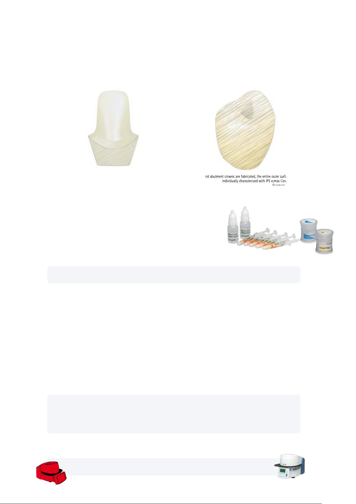
If hybrid abutments are fabricated, only the area of the
emergence profile is characterized with IPS e.max CAD
Crystall./Shades, Stains and Glaze.
If hybrid abutment crowns are fabricated, the entire outer surface
Required materials
– IPS e.max CAD Crystall./Shades are ready-to-use "Dentin" stains in syringes.
Shade
Incisal 1
Shade
Incisal 2
Shade 0 Shade 1 Shade 2 Shade 3 Shade 4
– IPS e.max CAD Crystall./Stains are ready-to-use intensive stains in syringes.
cream sunset copper olive khaki mahogany
white
– IPS e.max CAD Crystall./Glaze Paste is a ready-to-use glazing paste.
– IPS e.max CAD Crystall./Glaze Liquid is a special liquid for mixing with Shades, Stains and Glaze.
may be individually characterized.
Note:
The IPS e.max CAD Crystall./Glaze Spray is not recommended for glazing IPS e.max CAD Abutment Solutions,
as it requires very targeted application. The glazing material must neither reach the bonding surface to the Ti
base nor the screw channel, as this may compromise the accuracy of fit.
27
Page 28
Preparing for Combination firing (Crystallization and Stain/Glaze firing in one step)
– Clean the ceramic structure with the steam jet to remove any contaminations and grease residue. Any contamination
after cleaning must be prevented.
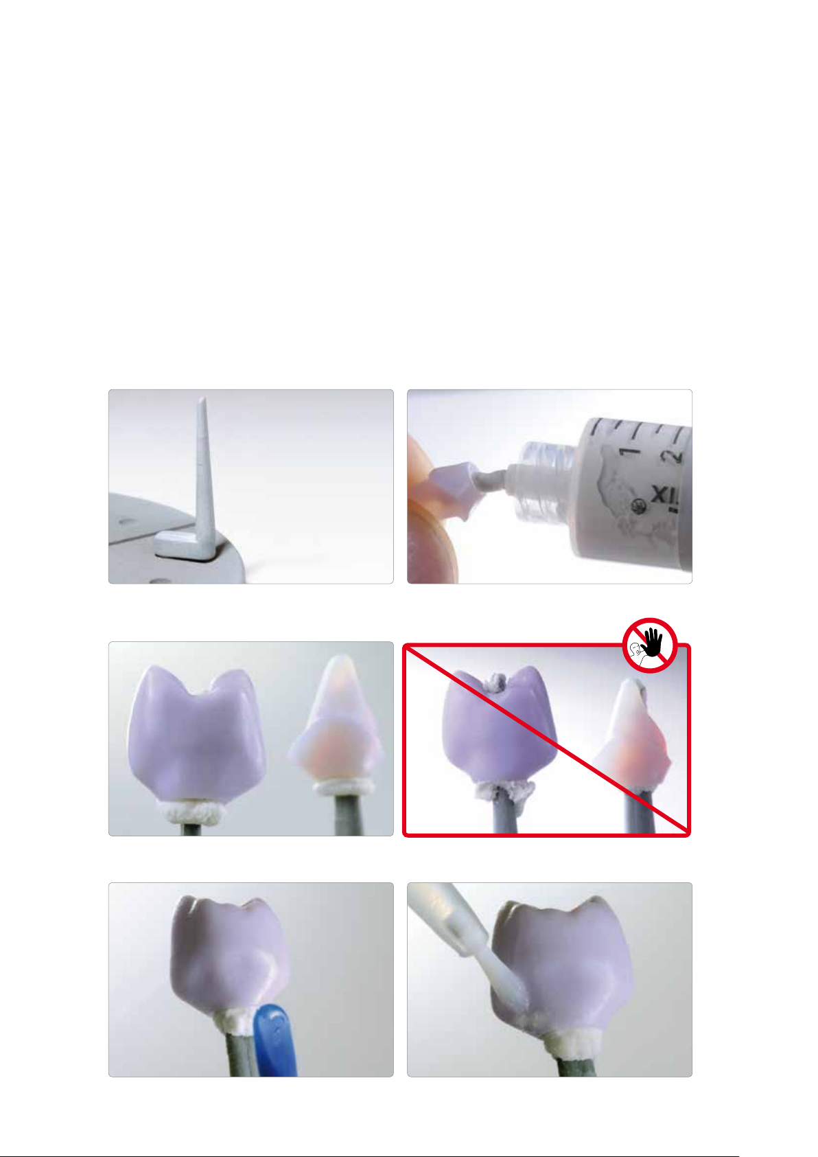
– Use the IPS e.max CAD Crystallization Pin XS for the crystallization of the ceramic structure.
– Fill the interface of the ceramic structure with either IPS Object Fix Putty or Flow auxiliary firing paste. Immediately
reseal the IPS Object Fix Putty/Flow syringe after extruding the material.
– Press the IPS e.max CAD Crystallization Pin XS only slightly into the IPS Object Fix Putty/Flow. Important: Do not
press the pin in too deep to make sure that it does not touch the walls. This may lead to cracks in the ceramic
structure.
– Smooth out displaced auxiliary firing paste using a plastic spatula so that the pin is securely in place.
– Prevent contamination of the outer surface / occlusal surface of the ceramic structure.
– Clean off any possible contamination with a brush dampened with water and dry.
The IPS e.max CAD Crystallization Pin XS is used for the crystallization of the ceramic
structure.
Important: – The IPS e.max CAD Crystallization Pin XS should be pressed
only slightly into the IPS Object Fix Putty/Flow so that it does not touch the walls of
the ceramic structure.
The interface of the ceramic structure is filled with either IPS Object Fix Putty or Flow
Incorrect: Pin pressed in too deep. Pin touches the ceramic structure,
auxiliary firing paste.
which may lead to cracks.
Displaced auxiliary firing paste is smoothed out with a plastic spatula from the margin
towards the support pin so that the pin is secured in the paste.
Any possible residue adhering to the outer surface/occlusal surface is cleaned off with
28
a brush dampened with water and dried.
Page 29

Combination firing (Crystallization and Stain/Glaze firing in one step)
Please observe the following procedure for the combination firing:
– Extrude the ready-to-use IPS e.max CAD Crystall./Glaze Paste from the syringe and mix.
– If a slight thinning is desired, the ready-to-use glaze may be mixed with a small amount of IPS e.max CAD Crystall./Glaze
Liquid.
Important:
– The glazing material must neither reach the bonding surface to the Ti base nor the screw channel, as this may
compromise the accuracy of fit. Check the interface before firing and carefully remove any contamination.
– On the abutment, do not apply any materials to the bonding surface to the crown, as this might compromise the fit
of the crown.
– Apply IPS e.max CAD Crystall./Glaze Paste evenly on the areas to be glazed using a small brush. Avoid to apply too thick
a glaze layer. Avoid "pooling", especially on the occlusal surface of the abutment crown.
– Too thin a glaze layer may lead to an unsatisfactory gloss.
– Apply characterizations with IPS e.max CAD Crystall./Shades and/or IPS e.max CAD Crystall./Stains. For that purpose,
extrude the Shades and Stains from the syringe and mix. If necessary, slightly thin them using IPS e.max CAD Crystall./
Glaze Liquid. However, the consistency should still remain pasty.
– Apply mixed Shades and Stains directly into the unfired glaze layer using a fine brush. More intensive shades are
achieved by several staining procedures and repeated firing, not by applying thicker layers.
– To imitate the incisal area and translucency of the hybrid abutment crown in the incisal and occlusal third, IPS e.max
CAD Crystall./Shades Incisal may be used. The cusps and fissures can be individualized using Stains.
Completing the IPS e.max CAD Ceramic Structure – Staining Technique on the Blue Restoration
Optional:
For minor shape adjustments (e.g. proximal or occlusal contact points), IPS e.max CAD Crystall./AddOn is available. The detailed procedure is described on page 33.
After glazing and staining, the Combination firing is conducted in a compatible ceramic furnace
(e.g. Programat
observe the following points:
– Place the restoration in the centre of the IPS e.max CAD Crystallization Tray.
– A maximum of 6 units can be positioned on the firing tray and crystallized in the Combination firing with IPS e.max CAD
Crystall./Glaze Paste.
Important
– Conduct the Combination firing on the IPS e.max CAD Crystallization Tray using the stipulated firing
parameters.
– Note:
If a restoration made of IPS e.max CAD MO and one made of IPS e.max CAD LT are to be crystallized in the same
firing, the firing parameters for IPS e.max CAD MO must be used!
®
CS or Programat P500). When placing the objects into the furnace and setting the firing parameters,
Observe the firing parameters for IPS e.max CAD MO and IPS e.max CAD LT. Firing parameters
see page 64
– Remove restoration from the furnace after completion of the firing cycle (wait for the acoustic signal of the furnace).
– Allow the objects to cool to room temperature in a place protected from draft.
– Do not touch the hot objects with metal tongs.
29
Page 30

IPS e.max CAD Crystall./Glaze Paste is extruded from the syringe and mixed.
If required, the paste can be thinned with IPS e.max CADCrystall./Glaze Liquid.
IPS e.max CAD Crystall./Glaze Paste is applied evenly on the emergence profile of the
hybrid abutment or the outer surface of the hybrid abutment crown.
Important: The glazing material must reach neither the bonding surface to the Ti base
nor the screw channel, as this may compromise the accuracy of fit.
Individual characterizations of the emergence profile are applied using IPS e.max CAD
Crystall./Shades.
Important: The materials must not be applied to the bonding surface to the crown,
Enhancing the chroma on the buccal surface with IPS e.max CAD Crystall./Shades
as this might compromise the fit of the crown.
30
Page 31

IPS e.max CAD Crystall./Shade Incisal is applied to imitate the incisal area.
Optional: For minor shape adjustments (e.g. proximal contact points), IPS e.max CAD
Crystall./Add-On is available.
Completing the IPS e.max CAD Ceramic Structure – Staining Technique on the Blue Restoration
The ceramic structure is placed in the centre of the IPS e.max CAD Crystallization Tray.
The Combination firing is conducted using the stipulated firing parameters. The
firing parameters for IPS e.max CAD MO and IPS e.max CAD LT must be observed.
The ceramic structure is removed from the furnace after completion of the firing cycle
(wait for the acoustic signal of the furnace).
Optional
Corrective firing
If characterizations or adjustments are required after crystallization, a corrective firing using
IPS e.max CAD Crystall./Shades and Stains and Glaze can be conducted. Conduct the corrective
firing also on the IPS e.max CAD Crystallization Tray.
For minor shape adjustments (e.g. proximal or occlusal contact points), IPS e.max CAD Crystall./Add-On is available.
The detailed procedure is described on page 33.
Once the IPS e.max CAD ceramic structure has cooled to room temperature, proceed with the following steps:
– Remove the ceramic structure from the IPS e.max CAD Crystallization Pin XS.
– Remove any residue with ultrasound in a water bath and/or with the steam jet.
– Do not remove residue with Al2O3 or glass polishing beads.
– Place the ceramic structure on the Ti base and check the fit.
– If adjustments by grinding are required, make sure that no overheating of the ceramic occurs.
31
Page 32

The ceramic structure is removed from the IPS e.max CAD Crystallization Pin XS.
Residue is removed with ultrasound in a water bath….
… or with the steam jet.
Residue must not be removed with Al
or glass polishing beads.
2O3
Glazed and characterized ceramic structures (hybrid abutment crown and hybrid abutment)
32
Page 33

Optional
Shape adjustments with IPS e.max CAD Crystall./Add-On
For minor shape adjustments (e.g. proximal contact points), IPS e.max CAD Crystall./Add-On is available. The adjustments
may be made with both the Combination firing or a separate Corrective firing.
Processing
– Mix IPS e.max CAD Crystall/Add-On with IPS e.max CAD Crystall/Add-On Liquid to an easy-to-contour consistency.
– Ensure even mixing of the add-on material and the liquid in order to achieve an optimum firing result.
– Apply the mixed add-on material directly on the unfired Glaze Paste and/or Shades and Stains in the areas to be adjusted
and fire.
– Conduct the Combination firing if Add-On is applied on the "blue" partially crystallized restoration.
– Conduct the Corrective firing if Add-On is applied on an already crystallized restoration.
Completing the IPS e.max CAD Ceramic Structure – Staining Technique on the Blue Restoration
Mixing IPS e.max CAD Crystall/Add-On with IPS e.max
CAD Crystall/Add-On Liquid to an easy-to-contour
consistency
Firing parameters see page 64
next working step … Permanent cementation Ti base / ceramic structure page 46
Application of the mixed Add-On on the blue restoration
before crystallization or on the crystallized restoration
33
Page 34

Staining technique on the "tooth-coloured" restoration
Staining technique on the "tooth-coloured" restoration
Characterization/Glaze
IPS e.max CAD Crystall./
Crystallization
Characterization/Glaze
Crystallization without application of any materials; separate Characterization/Glaze firing with either IPS e.max CAD Crystall./ or IPS e.max Ceram materials.
Crystallization
The following steps must be observed:
– Use the IPS e.max CAD Crystallization Pin XS for the crystallization of the ceramic structure.
– Fill the interface of the ceramic structure with either IPS Object Fix Putty or Flow auxiliary firing paste. Immediately
reseal the IPS Object Fix Putty/Flow syringe after extruding the material.
– Slightly press the IPS e.max CAD Crystallization Pin XS into the IPS Object Fix Putty/Flow. Important: Do not press
the pin in too deep to make sure that it does not touch the walls. This may lead to cracks in the ceramic
structure.
– Smooth out displaced auxiliary firing paste using a plastic spatula so that the pin is securely in place.
– Prevent contamination of the outer restoration surface. Clean off contamination with a brush dampened with water and
dry.
– Place the ceramic structure in the centre of the IPS e.max CAD Crystallization Tray.
firing
firing
IPS e.max Ceram
Important
– Conduct the crystallization on the IPS e.max CAD Crystallization Tray using the stipulated firing parameters.
Observe the firing parameters for IPS e.max CAD MO and IPS e.max CAD LT. Firing parameters
see page 64
– Note:
If a restoration made of IPS e.max CAD MO and one made of IPS e.max CAD LT are to be crystallized in the same
firing, the firing parameters for IPS e.max CAD MO must be used!
The IPS e.max CAD Crystallization Pin XS should be used for the crystallization of the
ceramic structure.
The interface of the ceramic structure is filled with either IPS Object Fix Putty or Flow
34
auxiliary firing paste.
Page 35

Important: – The IPS e.max CAD Crystallization Pin XS is only slightly pressed
into the IPS Object Fix Putty/Flow so that it does not touch the walls of the ceramic
structure.
Incorrect: Pin pressed in too deep. Pin touches the ceramic structure. This may lead
to cracks in the ceramic structure.
Displaced auxiliary firing paste is smoothed out with a plastic spatula from the margin
towards the support pin so that the pin is secured in the paste.
Conduct the crystallization using the stipulated firing parameters. The firing param-
eters for IPS e.max CAD MO and IPS e.max CAD LT must be observed.
Any possible residue adhering to the outer surface is cleaned off with a brush
dampened with water and dred.
Crystallized ceramic structures
– Remove ceramic structures from the furnace after completion of the firing cycle (wait for the acoustic signal of the furnace).
– Allow the objects to cool to room temperature in a place protected from draft.
– Do not touch the hot objects with metal tongs.
– Remove the ceramic structure from the IPS e.max CAD Crystallization Pin.
– Remove any residue with ultrasound in a water bath and/or with the steam jet.
– Do not remove residue with Al2O3 or glass polishing beads.
– Place the ceramic structure on the Ti base and check the fit.
– If adjustments by grinding of the restoration are required, make sure that no overheating of the ceramic
occurs.
Completing the IPS e.max CAD Ceramic Structure – Staining Technique on the Tooth-Coloured Restoration
next working step, either...
Stain / Glaze firing with IPS e.max CAD Crystall./; page 36
Stain / Glaze firing with IPS e.max CAD Ceram; page 40
35
Page 36

Characterization/Glaze firing with IPS e.max CAD Crystall./…
individually characterized.
The following paragraphs will explain the steps of characterizing and glazing with IPS e.max CAD Crystall./Shades, Stains
and Glaze.
If hybrid abutments are fabricated, only the area of the
emergence profile is characterized with
IPS e.max CAD Crystall./Shades, Stains and Glaze.
If hybrid abutment crowns are fabricated, the entire outer surface may be
Required materials
– IPS e.max CAD Crystall./Shades are ready-to-use "Dentin" stains in syringes.
Shade
Incisal 1
Shade
Incisal 2
Shade 0 Shade 1 Shade 2 Shade 3 Shade 4
– IPS e.max CAD Crystall./Stains are ready-to-use intensive stains in syringes.
cream sunset copper olive khaki mahogany
white
– IPS e.max CAD Crystall./Glaze Paste is a ready-to-use glazing paste.
– IPS e.max CAD Crystall./Glaze Liquid is a special liquid for mixing with Shades, Stains and Glaze.
individually characterized.
Note:
The IPS e.max CAD Crystall./Glaze Spray is not recommended for glazing IPS e.max CAD Abutment Solutions,
as is requires very targeted application. The glazing material must neither reach the bonding surface to the Ti
base nor the screw channel, as this may compromise the accuracy of fit.
36
Page 37

Please observe the following procedure for the Characterization/Glaze firing:
– Extrude the ready-to-use IPS e.max CAD Crystall./Glaze Paste from the syringe and mix.
– If a slight thinning is desired, the ready-to-use glaze may be mixed with a small amount of IPS e.max CAD Crystall./
Glaze Liquid.
Important:
– The glazing material must neither reach the bonding surface to the Ti base nor the screw channel, as this may
compromise the accuracy of fit. Check the interface before firing and carefully remove any contamination.
– On the hybrid abutment, do not apply any materials to the bonding surface to the crown, as this might
compromise the fit of the crown.
– Apply IPS e.max CAD Crystall./Glaze Paste evenly on the areas to be glazed using a small brush. Avoid to apply too thick
a glaze layer. Avoid "pooling", especially on the occlusal surface of the hybrid abutment crown.
– Too thin a glaze layer may lead to an unsatisfactory gloss.
– Apply characterizations with IPS e.max CAD Crystall./Shades and/or IPS e.max CAD Crystall./Stains. For that purpose,
extrude the Shades and Stains from the syringe and mix. If necessary, slightly thin them using IPS e.max CAD Crystall./
Glaze Liquid. However, the consistency should still remain pasty.
– Apply mixed Shades and Stains directly into the unfired glaze layer using a fine brush. More intensive shades are
achieved by several staining procedures and repeated firing, not by applying thicker layers.
– To imitate the incisal area and translucency of the abutment crown in the incisal and occlusal third, IPS e.max CAD
Crystall./Shades Incisal may be used. The cusps and fissures can be individualized using Stains.
After glazing and staining, the Characterization/Glaze firing (Corrective firing) is conducted in a compatible ceramic furnace
(e.g. Programat
®
CS or Programat P500). When placing the objects into the furnace and setting the firing parameters,
observe the following points:
– Place the restoration in the centre of the IPS e.max CAD Crystallization Tray.
– A maximum of 6 units can be positioned on the firing tray for the firing with IPS e.max CAD Crystall./Glaze Paste.
Important
– Conduct the Corrective firing on the IPS e.max CAD Crystallization Tray using the stipulated firing
parameters.
Firing parameters see page 64
Completing the IPS e.max CAD Ceramic Structure – Staining Technique on the Tooth-Coloured Restoration
37
Page 38

IPS e.max CAD Crystall./Glaze Paste is extruded from the syringe and mixed. If
required, the paste is thinned with IPS e.max CADCrystall./Glaze Liquid.
IPS e.max CAD Crystall./Glaze Paste is applied evenly on the emergence profile of the
hybrid abutment or the outer surface of the hybrid abutment crown.
Important: The glazing material must reach neither the bonding surface to the Ti base
nor the screw channel or the bonding surface to the crown, as this may compromise
the accuracy of fit.
Enhancing the chroma of the buccal surface
Characterizing the emergence profile with Shades
IPS e.max CAD Crystall./Shade Incisal is applied to imitate the incisal area.
The Corrective firing is conducted on the IPS e.max CAD Crystallization Tray using the
stipulated firing parameters.
38
Page 39

Optional
Corrective firing
– If adjustments are required, another Corrective firing using IPS e.max CAD Crystall./Shades and
Stains and Glaze can be conducted. Conduct the Corrective firing also on the IPS e.max CAD
Crystallization Tray.
– For minor shape adjustments (e.g. proximal contact points), IPS e.max CAD Crystall./Add-On is
available. The adjustments may be made with both Crystallization/Glaze and Corrective firing.
– The detailed procedure is described on page 33.
Once the IPS e.max CAD ceramic structure has cooled to room temperature, proceed with the following steps:
– Remove the ceramic structure from the IPS e.max CAD Crystallization Pin XS.
– Remove any residue with ultrasound in a water bath and/or with the steam jet.
– Do not remove residue with Al2O3 or glass polishing beads.
– Place the ceramic structure on the Ti base and check the fit.
– If adjustments by grinding are required, make sure that no overheating of the ceramic occurs.
– If the restoration is ground, manually polish the corresponding areas to a high gloss after grinding.
The ceramic structure is removed from the IPS e.max CAD Crystallization Pin XS. Any residue is removed with ultrasound in a water bath or with the steam jet.
Residue must not be removed with Al2O3 or glass polishing beads.
Glazed and characterized ceramic structures (hybrid abutment and/or
hybrid abutment crown)
Completing the IPS e.max CAD Ceramic Structure – Staining Technique on the Tooth-Coloured Restoration
next working step … Permanent cementation Ti base / ceramic structure page 46
39
Page 40
Characterization/Glaze firing with IPS e.max Ceram
individually characterized with IPS e.max Ceram Shades,
The following paragraphs will explain the steps of characterizing and glazing with IPS e.max Ceram.
If hybrid abutments are fabricated, only the area of
the emergence profile is characterized with IPS e.max Ceram
Shades, Essences and Glaze.
If hybrid abutment crowns are fabricated, the entire outer surface may be
individually characterized with IPS e.max Ceram Shades,
Essences, and Glaze.
Required materials
– IPS e.max Ceram Essences are intensively shaded stains in powder form.
– IPS e.max Ceram Shades are ready-to-use stains in syringes.
– IPS e.max Ceram Glaze and Stain Liquid (allround, longlife) to mix the
materials in powder form (Essences, Glaze), as well as to thin paste materials
(Shades, Glaze).
IPS e.max CAD Crystall./Shades, Stains, Glaze and IPS e.max Ceram Shades, Essence, Glaze must not be
mixed with each other!
The following steps must be observed:
– Clean the finished ceramic structure with the steam jet to remove any contaminations and grease residue. Any conta-
mination after cleaning must be prevented.
– For better wetting of the stains, a small quantity of IPS e.max Ceram Glaze and Stain Liquid may be slightly rubbed into
the area that needs to be characterized.
– Mix the pastes or powders with the IPS e.max Ceram Glaze and Stain Liquid allround or longlife to the desired consistency.
– More intensive shades are achieved by several staining procedures and repeated firing, not by applying thicker layers.
– To imitate the incisal area and translucency of the hybrid abutment crown in the incisal and occlusal third, IPS e.max
Ceram Shade Incisal may be used. The cusps and fissures can be individualized using Essences.
– If hybrid abutments are fabricated, only the area of the emergence profile is characterized with IPS e.max Ceram Shades
and Essences.
– Secure the ceramic structure on the firing pin of the honey-comb tray with a little IPS Object Fix Putty or Flow for firing.
Important:
The characterization must neither reach the bonding surface to the Ti base nor the screw channel, as this may
compromise the accuracy of fit. Check the interface before firing and carefully remove any contamination.
On the hybrid abutment, do not apply any materials to the bonding surface to the crown, as this may compromise
the fit of the crown.
Conduct the Characterization/Glaze firing for IPS e.max Ceram on a honey-comb firing
tray using the stipulated firing parameters. Firing parameters see page 64
40
Page 41

IPS e.max Ceram Shade Incisal is applied to imitate the incisal area.
Enhancing the chroma of the buccal surface
Individual characterization of the emergence profile with IPS e.max Ceram Essences
The Stain and Characterization firing is conducted on a honey-comb firing tray.
– Remove restoration from the furnace after completion of the firing cycle (wait for the acoustic signal of the furnace).
– Allow the objects to cool to room temperature in a place protected from draft.
– Do not touch the hot objects with metal tongs.
Additional Characterization firings can be conducted with the same firing parameters.
Glaze firing
Glaze firing is conducted with powder or paste glaze. On abutments, only the emergence profile is glazed. On hybrid
abutment crowns, glaze is applied to the entire outer surface.
Required materials
– IPS e.max Ceram Glaze Paste, Glaze Powder are glazing materials in paste and powder
forms.
– IPS e.max Ceram Glaze and Stain Liquid (allround, longlife) to mix the materials in
powder form (Essences, Glaze), as well as to thin paste materials (Shades, Glaze)
IPS e.max CAD Crystall./Shades, Stains, Glaze and IPS e.max Ceram Shades, Essence, Glaze must not be
mixed with each other!
Completing the IPS e.max CAD Ceramic Structure – Staining Technique on the Tooth-Coloured Restoration
41
Page 42

The following procedure is recommended:
– For easier handling, the ceramic structure can be positioned on the Ti base for glazing. For that purpose, secure Ti base
on a model analog.
– Mix the glazing material (IPS e.max Ceram Glaze Paste or Powder) with the IPS e.max Ceram Glaze and Stain Liquid
allround or longlife to the desired consistency.
– Apply an even layer of glazing material covering all areas that are to be glazed.
– If required, the fluorescence may be increased by applying a fluorescing glazing material (paste or powder).
Important:
The glazing material must neither reach the bonding surface to the Ti base nor the screw channel, as this may
compromise the accuracy of fit. Check the interface before firing and carefully remove any contamination. On the
abutment, do not apply any glaze to the bonding surface to the crown, as this might compromise the fit of the
crown.
The IPS e.max CAD Crystall./Glaze Spray is not recommended for glazing IPS e.max CAD Abutment
Solutions, as is requires very targeted application. The glazing material must neither reach the bonding surface
to the Ti base nor the screw channel, as this may compromise the accuracy of fit.
Conduct the Characterization/Glaze firing for IPS e.max Ceram on a honey-comb firing
tray using the stipulated firing parameters. Firing parameters see page 64
An even layer of glaze material is applied to the emergence profile of the hybrid abutment. Care has to be taken that no glaze material enters the screw channel.
Care has to be taken that no glaze material is present on the interface of the hybrid
abutment and hybrid abutment crown prior to the firing cycle. The glaze material is
carefully removed, if necessary.
The glazing material is applied evenly on the outer surface of the hybrid abutment
crown. Care has to be taken that no glaze material enters the screw channel.
The Characterization/Glaze firing is conducted on a honey-comb firing tray with the
42
corresponding parameters.
Page 43

– Remove restoration from the furnace after completion of the firing cycle (wait for the acoustic signal of the furnace).
– Allow the objects to cool to room temperature in a place protected from draft.
– Do not touch the hot objects with metal tongs.
Optional
Shape adjustments of IPS e.max Ceram Add-On
Use IPS e.max Ceram Add-On Dentin and/or Incisal for shape adjustments after Glaze firing. Please observe the following
procedure for processing:
– Mix IPS e.max Ceram Add-On Dentin or Incisal with IPS e.max Ceram Build-Up Liquid soft or allround and apply on the
corresponding areas.
– Fire with the stipulated parameters for the "Add-On after Glaze firing". Observe long-term cooling!
– If necessary, polish the adjusted areas to a high gloss after firing.
Firing parameters see page 64
next working step … Permanent cementation Ti base / ceramic structure page 46
Completing the IPS e.max CAD Ceramic Structure – Staining Technique on the Tooth-Coloured Restoration
43
Page 44

CAD Abutment Solutions
Crown on IPS e.max CAD hybrid abutment
The crown on the IPS e.max Hybrid Abutment can be completed using either the staining technique or the cut-back
technique. To characterize and glaze, either the PS e.max CAD Crystall./ materials or the IPS e.max Ceram materials are
used.
Basically, the procedure for completing a crown is the same as that for a crown on a prepared tooth. For detailed
information about the procedure, please refer to the IPS e.max CAD Instructions for Use.
Example: IPS e.max CAD crown – Cut-back technique – IPS e.max Ceram
Partially reduced IPS e.max CAD restorations fitted on the model. Always observe minimum thicknesses!
For crystallization, the partially reduced IPS e.max CAD restorations are placed directly on the IPS e.max CAD Crystallization Tray using IPS Object Fix Putty or Flow.
The wash firing is conducted using e.g. IPS e.max Ceram Glaze, Shades and Essences.
44
Page 45

Completion of the anatomical shape of the reduced areas using IPS e.max Ceram Incisal and Opal materials
Finishing with diamond burs and design of a true-to-nature shape and surface structure Finally, glaze firing is conducted using IPS e.max Ceram Glaze.
Crown on an IPS e.max CAD Hybrid Abutment
IPS e.max CAD crown after glaze firing (partially reduced and veneered with IPS e.max Ceram) on a IPS e.max CAD hybrid abutment
45
Page 46
CAD Abutment Solutions
Permanent cementation of base / ceramic structure
Careful preparation of the bonding surface is a prerequisite for the successful adhesive cementation of the base and the
ceramic structure. The following paragraphs outline the required procedure. The procedure is the same for hybrid
abutments and hybrid abutment crowns.
Required materials
– IPS Ceramic Etching Gel
– Monobond® Plus
– Multilink® Hybrid Abutment
– Glyceringel (z.B. Liquid Strip)
IPS e.max CAD ceramic structure
(LS2)
Blasting –
Etching
Conditioning
Adhesive cementation Multilink
Covering the cementation joint Glycerine gel, e.g. Liquid Strip
Curing 7 minutes auto-polymerization
Polishing the cementation joint Conventional polishers for ceramic/composite resin
Preparation of the Ti base
The following procedure should be observed in the preparation of the Ti base for the cementation with the ceramic
structure:
– The Ti base should be prepared according to the instructions of the manufacturer.
– Clean the Ti base with an ultrasonic bath or with a steam cleaner and then dry it with blown air.
– Screw the Ti base on the model analog.
– Place the ceramic structure on the Ti base and mark the relative position of the components with a waterproof pen. This
facilitates locating the correct position when the parts are assembled at a later stage.
– The emergence profile of the base must not be blasted or modified in any way.
– If the manufacturer recommends that the bonding surface of the Ti base be blasted, the following procedure
should be observed:
– Apply silicone (Virtual Extra Light Body Fast Set) to protect the emergence profile and the screw channel .
– Carefully blast the bonding area according to the instructions of the manufacturer.
– Remove silicone.
– Clean the Ti base with ultrasound in a water bath or with the steam jet.
– After cleaning, the bonding surface must not be contaminated under any circumstances, as this would impair the
bond.
– Apply Monobond Plus on the clean bonding surface and allow it to react for 60 s. After the reaction time, disperse any
residue with air that is free of water and oil.
– Seal the screw channel with a foam pellet or wax. The bonding surface must not be contaminated in the process.
Bonding area to the base
®
Ceramic Etching Gel for 20 s
with IPS
The bonding area
with Monobond
According to the instructions of the
®
Plus for 60 s
®
Hybrid Abutment
Base
manufacturer
–
46
Page 47

Application Procedure – Permanent Cementation
The Ti base is screwed on the model analog. The relative position to the ceramic
structure is marked with a waterproof pen.
The bonding surface can be carefully blasted according to the instructions of the
manufacturer.
E.g. silicone (Virtual Extra Light Body Fast Set) is applied in order to protect the
Removal of the silicone and subsequently cleaning with ultrasound in a water bath
emergence profile and the screw channel.
or with the steam jet.
Monobond Plus is applied to the clean bonding surface and allowed to react for
60 s. After the reaction time, any remaining residue is dried with blown air that is
free of water and oil.
The screw channel is sealed with a foam pellet or wax.
The bonding surface must not be contaminated in the process.
47
Page 48

Preparing the ceramic structure
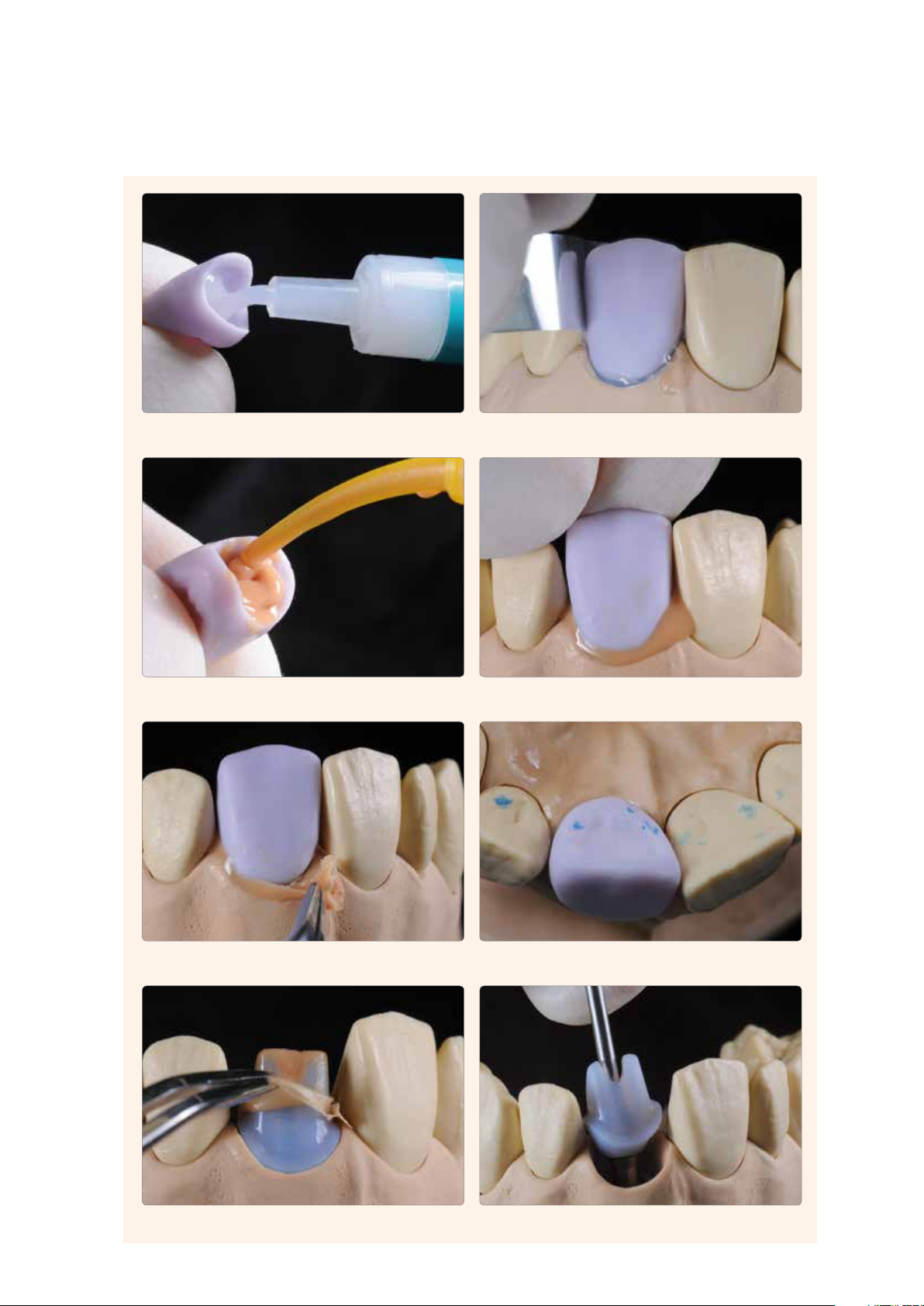
The following procedure must be observed in the preparation of the ceramic structure for cementation on the Ti base:
– Do not blast the ceramic structure in preparation for the cementation.
– Clean the ceramic structure in an ultrasonic bath or with a steam cleaner and subsequently blow dry.
– After cleaning, the bonding surface must not be contaminated under any circumstances, as this would impair the bond.
– Wax can be applied to protect the outer surfaces or the glazed areas.
– Etch the bonding surface with 5% hydrofluoric acid gel (IPS Ceramic Etching Gel) for 20 s.
– Subsequently, thoroughly rinse the bonding surface under running water and dry with air that is free of water and oil.
– Apply Monobond Plus on the clean bonding surface and allow it to react for 60 s. After the reaction time, dry any
remaining residue with blown air that is free of water and oil.
The ceramic structure must not be blasted. Etching with IPS Ceramic Etching Gel for 20 seconds.
Subsequently, the restoration is rinsed with water and
blown dry.
Monobond Plus is allowed to react for 60 s,
and excess is blown dry.
48
Page 49

Cementation with Multilink® Hybrid Abutment
The following instructions must be observed in the cementation procedure:
– The cleaned and conditioned components (ceramic structure, Ti base) are laid out ready for cementation.
– The subsequent cementation procedure must be carried out quickly and without interruption. The working
time of Multilink Hybrid Abutment is approximately 2 min at 23 °C (± 1 °C) or 73 °F (± 1.8 °F).
– As a general rule, a new mixing tip is attached to the Multilink Hybrid Abutment syringe prior to each use.
– Apply a thin layer of Multilink Hybrid Abutment directly from the mixing syringe to the bonding surface of the Ti base
and the bonding surface of the ceramic structure.
– The mixing tip is left on the Multilink Hybrid Abutment syringe until the next use. The remaining cement polymerizes in
the tip and functions as a seal.
– Place the ceramic structure on the Ti base in such a way that the position markings are aligned.
– Press the parts lightly and evenly together and check the correct relative position of the components (transition Ti base/
ceramic structure).
– Subsequently, press the parts tightly together for 5 s.
– Carefully remove excess in the screw channel, e.g. with a Microbrush or brush, using rotary movements.
Important:
– Important: Excess must not be removed before curing has started, i.e. 2-3 minutes after mixing. For the
purpose, a suitable dental lab instrument (e.g. Le Cron) is used. The components are held in place with
light pressure in the process.
– Glycerine gel is applied (e.g. Liquid Strip) on the cementation joint to prevent the formation of an inhibition layer. The
glycerine gel must be applied cautiously to avoid blending it with or displacing the composite. Make sure to leave the gel
on the cementation joint until polymerization is complete.
– Next, the luting composite is completely auto-polymerized within 7 min.
– Important: Do not move the components until Multilink Hybrid Abutment has completely cured. They can be
held immobile with e.g. diamond-coated tweezers.
– After the completion of auto-polymerization, rinse off the glycerine gel with water.
– Make sure to cautiously polish the cementation joint with rubber polishers at a low speed (< 5,000 rpm) to
avoid overheating.
– Remove any cement residue left in the screw channel with suitable rotating instruments.
– Clean the restoration with ultrasound in a water bath or with the steam jet.
Application Procedure – Permanent Cementation
The cleaned and conditioned components are laid out ready for cementation. A new mixing tips is attached to the Multilink Hybrid Abutment prior to each use.
49
The Multilink Hybrid Abutment mixing syringe is attached.
Page 50

A thin layer of Multilink Hybrid Abutment is directly applied from the mixing tip to the
bonding surface of the Ti base.
A thin layer of Multilink Hybrid Abutment is directly applied from the mixing tip
on the bonding surface of the ceramic structure.
5 s
The ceramic structure is placed on the Ti base in such a way that the position markings
are aligned. The components are joined using even and light pressure and the relative
position of the components is checked (transition base/ceramic structure).
Excess in the screw channel is carefully removed, e.g. with a Microbrush or brush,
using rotary movements.
Subsequently, the components are tightly pressed together for 5 s.
2-3 m
Important: Excess must not be removed before curing has started,
i.e. 2–3 minutes after mixing. The components are held in place with
light pressure in the process.
7 min
Glycerine gel (e.g. Liquid Strip) is applied on the cementation joint to prevent the
formation of an inhibition layer.
Important: The components must not be moved until auto-polymerization
is completed. The components must be immobilized during this time.
The luting composite auto-polymerizes within 7 min.
50
Page 51

Application Procedure – Permanent Cementation
After the completion of auto-polymerization, the glycerine gel is rinsed off with water.
Any remaining cement residue in the screw channel is removed with suitable rotating
instruments. The Ti base must no be damaged.
The cementation joint is cautiously polished with rubber polishers at
Completed hybrid abutment and hybrid abutment crown after cementation
low speed (< 5,000 rpm), to avoid overheating.
51
Page 52

CAD Abutment Solutions
Seating and Aftercare
Sterilization
The hybrid abutments or hybrid abutment crowns must be sterilized prior to insertion.
Furthermore, the locally applicable legal regulations and the hygiene standards
applicable for a dental practice must be observed.
Steam sterilization can be performed with the 3 x fractionated pre-vacuum with the
following parameters: Sterilization time 3 min; steam temperature 132 °C/270 °F;
resulting in a half-cycle exposure time of 1.5 min. The abutment is for immediate use.
No storage after sterilization!
The responsibility for the sterility of the hybrid abutment or hybrid abutment crown lies with the user. It must be ensured
that only suitable devices, materials and product-specifically validated methods are used to perform sterilization.
The equipment and devices must be properly maintained and serviced at regular intervals. The fabricator (dental technician)
of the IPS e.max CAD Abutment Solution must inform the dentist of the need to sterilize the abutment before inserting it
in the patient’s mouth!
Intraoral preparation
Please observe the following procedure to prepare for the permanent cementation of the implant-supported restoration:
– Remove the temporary restoration.
– Clean the implant site.
– Check the periimplant tissue (emergence profile).
52
Page 53

Seating the hybrid abutment and crown
Preparing/conditioning the hybrid abutment with dedicated crown
Conditioning of the ceramic surface, i.e. the bonding surface, in preparation for cementation is critical for generating a
sound bond between the cementation material and the all-ceramic material.
The following procedure must be observed in the preparation of the ceramic structure for cementation on the Ti base:
– Do not blast IPS e.max CAD hybrid abutment or IPS e.max CAD crown with Al
– Ideally, the clinical try-in is conducted before etching to prevent contamination of the bonding surface.
– Thoroughly clean the hybrid abutment and crown with water and subsequently blow dry.
– Etch the bonding surface with 5% hydrofluoric acid gel (IPS Ceramic Etching Gel) for 20 s. The etching gel must not
come into contact with the emergence profile or the outer side of the crown. Important: No intraoral application of
the IPS Ceramic Etching Gel.
– Subsequently, thoroughly rinse the bonding surface under running water and dry it with air that is free or water and oil.
– If an adhesive or self-adhesive cementation protocol is used, apply Monobond Plus to the clean bonding surface and
allow it to react for 60 s. After this reaction time, disperse any residue with air that is free of water and oil.
or glass polishing beads.
2O3
Seating and Aftercare
The IPS e.max CAD ceramic structures must not be
blasted in preparation for cementation.
The bonding surfaces are etched with IPS Ceramic
Etching Gel and subsequently cleaned.
53
Monbond Plus is applied to the bonding surfaces,
and allowed to react for 60 s. Excess is dispersed
with air.
Page 54

Seating the hybrid abutment and dedicated crown
Note:
Temporary insertion of the IPS e.max CAD crown on the IPS e.max CAD hybrid abutment is contraindicated!
For the permanent seating of the hybrid abutment and the crown, please observe the following working steps. Please also
observe the Instructions for Use of the selected luting material.
SpeedCEM® is recommended for the seating of IPS e.max CAD crowns on
IPS e.max hybrid abutments.
– Do not use phenolic mouth washes, as such products negatively influence the bond between the ceramic and the
composite.
– Insert the hybrid abutment intraorally into the implant.
– Manually screw in the matching implant screw.
– Tighten the implant screw with a torque wrench (observe the instructions of the manufacturer).
– Insert a cotton or foam pellet into the screw channel.
– Seal the screw channel with a temporary composite (e.g. Telio® CS Inlay). This serves to ensure access to the screw at a
later stage.
– Check the bonding area for contamination/moisture and clean or dry with an air syringe, if necessary.
– Apply the luting material, e.g. SpeedCEM, into the conditioned crown.
– Place the crown onto the hybrid abutment and secure in place in the final position.
– Conduct the pre-polymerization using the four-quarter technique.
– Remove excess luting material.
– Cover the cementation joint with glycerine gel (e.g. Liquid Strip).
– Polymerize with an LED curing light (e.g. Bluephase®).
– Rinse off the glycerine gel with water.
– Check the occlusion and articulation and make adjustments, if necessary. If adjustments are made to the restoration by
grinding, these areas must subsequently be polished to a high gloss, e.g. using OptraFine.
– Polish restoration margins and the cementation joint with silicone polishers (e.g. Astropol®, OptraFine).
– Apply Cervitec Plus in the area of the gingival margin.
The hybrid abutment is inserted into the implant intraorally. The matching implant screw is screwed in manually.
54
Page 55

Seating and Aftercare
The implant screw is tightened with a torque wrench (the instructions of the
manufacturer must be observed).
The luting material, e.g. SpeedCEM, is applied into the conditioned crown.
The screw channel is sealed, for instance with a cotton or foam pellet
The crown is placed on the hybrid abutment and secured in place.
and a temporary composite material.
Pre-polymerization using the four-quarter technique
The restoration margin is covered with glycerine gel (e.g. Liquid Strip).
Excess luting material is removed.
The luting material is cured with an LED curing light (e.g. Bluephase).
55
Page 56

The glycerine gel is rinsed off with water. The occlusion and articulation is checked and adjustments are made, if necessary.
The restoration margins and the cementation joint are polished (e.g. OptraPol,
OptraFine).
Completed IPS e.max CAD hybrid abutment and crown
56
Page 57

Seating the hybrid abutment crown
Preparing/Conditioning the Hybrid Abutment Crown
Please observe the following notes to prepare for the intraoral sealing of the screw channel:
– As a general rule, do not blast IPS e.max CAD hybrid abutment crowns with Al
– Thoroughly clean the the hybrid abutment crown with water and blow dry.
– Etch the screw channel from the occlusal side with 5% hydrofluoric acid gel (IPS Ceramic Etching Gel) for 20 seconds.
Make sure that no etching gel comes into contact with the occlusal surface. Important: Do not use the IPS Ceramic
Etching Gel intraorally.
– Thoroughly rinse off the etching gel with water and dry with oil- and water-free air.
– Apply Monobond Plus to the etched and cleaned surface in the screw channel, allow to react for 60 seconds and then
disperse excess with oil- and water-free air.
or glass polishing beads.
2O3
Seating and Aftercare
IPS e.max CAD ceramic structures must not be blasted. The screw channel is etched with IPS Ceramic Etching
Gel for 20 s and subsequently cleaned.
Monobond Plus is applied, allowed to react for
60 s and excess is dispersed.
Seating the hybrid abutment crown
For the permanent seating of the hybrid abutment crown, please observe the following working steps:
– Do not use phenolic mouth washes, as such products negatively influence the bond between the ceramic and the
composite.
– Insert the hybrid abutment crown intraorally into the implant.
– Manually screw in the matching implant screw.
– Tighten the implant screw with a torque wrench (observe the instructions of the manufacturer).
– Check the screw channel for contamination/moisture and clean with Total Etch (phosphoric acid gel), if necessary.
– Insert a cotton or foam pellet into the screw channel.
– Apply the bonding agent, followed by polymerization.
– Seal the screw channel with a composite material (e.g. Tetric EvoCeram) in the appropriate shade.
– Polymerize with an LED curing light (e.g. Bluephase).
– Check the occlusion/articulation after polymerization and correct possible rough spots with suitable fine-grit diamonds.
– Polish to a high gloss with silicone polishers (e.g. OptraPol/OptraFine).
57
Page 58

The hybrid abutment crown is inserted into the implant intraorally.
The matching implant screw is screwed in manually.
The implant screw is tightened with a torque wrench (the instructions of the manufacturer must be observed).
Polymerization with an LED curing light (e.g. Bluephase)
The screw channel is sealed with a composite material (e.g. Tetric EvoCeram) in the
After polymerization, the occlusion/articulation is checked and possible rough spots are
adjusted with suitable finishers or fine diamonds.
appropriate shade.
High-gloss polishing is performed using silicone polishers (e.g. Astropol P, Astropol HP
or Astrobrush).
Completed IPS e.max CAD hybrid abutment crown
58
Page 59

Care notes – Implant Care
Implant Care comprises a range of coordinated products for the professional care of patients during the various phases of
implant treatment and lifelong aftercare. Products for professional tooth cleaning and bacterial control contribute to the
long-term quality assurance of implant-supported restorations. Structural elements peri-implant tissue, natural teeth, dental
restorations, gingiva and the mucosa are treated in an optimum way with regard to function and esthetics.
Seating and Aftercare
59
Page 60

CAD Abutment Solutions
General Information
Frequently Asked Questions
In addition to the desired tooth shade, why should the root
shade also be defined/ determined upon shade determination?
IPS e.max CAD Abuttment Solutions allow you to fabricate restorations with a lifelike appearance both in the visible area and the area
below the gingiva (root). By defining the root shade, a highly esthetic
outcome can be achieved especially in the case of receding gingiva.
Is it possible to fabricate an abutment or an abutment crown
with IPS e.max CAD (LS
No! For this indication, IPS e.max CAD needs the support provided
by the Ti base. In addition, the Ti base allows an optimum (industrially
fabricated) fit to the implant to be achieved.
Which Ti bases can be used for the fabrication of IPS e.max
CAD Abutment Solutions?
Only Ti bases of authorized CAD/CAM systems may be used.
More information about the CAD/CAM cooperation systems is
available on the Internet from www.ivoclarvivadent.com.
) without using a Ti base?
2
Do IPS e.max CAD ceramic structures have to be glazed in all
cases?
No. High gloss can also be achieved by a corresponding polishing
procedure. The polishing technique (before crystallization) is preferably used for the emergence profile of the hybrid abutment.
For the hybrid abutment crown, the application of glaze is
recommended.
Is it possible to use an IPS e.max CAD hybrid abutment as an
abutment for a bridge restoration?
No. Only single-tooth restorations may be fabricated.
Can different CAM units be used for milling the IPS e.max CAD
ceramic structure (abutment) and the dedicated IPS e.max CAD
crown?
If different CAM units are used, inaccuracies of fit may occur in
unfavourable cases. Therefore, both IPS e.max CAD objects
(abutment, crown) should be ideally milled in the same CAM unit.
Is it permissible to modify the selected Ti base?
The Ti base must not be adjusted by grinding, as this would compromise the fit of the IPS e.max CAD ceramic structure.
The instructions of the manufacturer regarding the preparation for
permanent cementation must be observed.
Is a hybrid abutment crown indicated in the anterior region?
This indication depends on the position and inclination of the
implant. If the opening of the screw channel is located on the oral
surface, a hybrid abutment crown may be fabricated in the anterior
region.
May a hybrid abutment crown be cut-back and subsequently
supplemented with IPS e.max Ceram layering materials.?
No. For implant-supported restorations, it is recommended to
fabricate monolithic restorations (without veneer). In this way,
chipping of the layering ceramic is prevented.
Can a clinical try-in be conducted with the IPS e.max CAD
Abutment Solutions? How are the ceramic structures prepared
for this?
Yes. Clinical try-in may be performed either before or after crystallization of the IPS e.max CAD ceramic structures. The Ti base and
IPS e.max CAD ceramic structure are temporarily joined in the
laboratory by means of a silicone material, e.g. Virtual Extra Light
Body Fast Set. This facilitates the intraoral handling during clinical
try-in with the patient.
What must be observed for the clinical try-in of a crown on
a hybrid abutment?
To check the occlusion/articulation and to make possible
adjustments, the crown must be temporarily secured on the hybrid
abutment with a silicone material, e.g. Virtual Extra Light Body Fast
Set. The silicone material acts as a buffer and prevents chipping in
the marginal area of the crown. Try-in pastes or Vaseline must not be
used for functional checks.
60
Page 61

Can a glaze spray be used for glazing IPS e.max CAD ceramic
structures (e.g. IPS e.max CAD Crystall./Glaze Spray)?
We do not recommend using the Glaze Spray for the indications
hybrid abutment or hybrid abutment crown, as there is a risk that
the bonding surface to the Ti base or the scew channel are contamination with glaze.
What material is used to permanently cement the IPS e.max
CAD ceramic structures to the Ti base?
Only Multilink Hybrid Abutment is to be used for permanent cementation. This ensures a high-quality bond. Given the high opacity of
the luting composite, complete optical masking of the Ti base is
achieved and thus an excellent esthetic appearance ensured.
How is the Ti base prepared for the permanent cementation
with Multilink Hybrid Abutment?
Provided it has been approved by the manufacturer, carefully blast
the bonding area with Al
at low pressure until an even mat
2O3
surface has been achieved. After cleaning, the area is conditioned
with Monobond Plus.
General Information – Frequently Asked Questions
How is the screw channel of a hybrid abutment crown sealed
after seating?
The screw channel is extraorally conditioned (etching, silanating).
After the restoration has been intraorally screwed down on the
implant, the screw channel is sealed with a restorative composite.
61
Page 62

Material Selection Table
Ti base
Bleach BL and A-D Shade Guide
Multilink Hybrid Abutment HO 0*
LT
D4
LT
D3
LT
D2
LT
C4
LT
C3
LT
C2
LT
C1
LT
B4
LT
B3
LT
B2
LT
B1
e.g. SpeedCEM
LT
A4
Bleach BL and A-D Shade Guide
LT
A3.5
Adhesive, self-adhesive or conventional cementation,
LT
A3
1
LT
D4
1
LT
D3
LT
D2
1
LT
C4
1
LT
C3
LT
C2
LT
C1
1
LT
B4
1
LT
B3
LT
B2
Ti base
LT
B1
1
LT
A4
Multilink Hybrid Abutment HO 0*
LT
A3.5
LT
A3
IPS e.max CAD hybrid abutment and IPS e.max CAD dedicated crown
The material is selected on the basis of the desired tooth shade (Bleach BL or A–D). Depending on the geometry of the hybrid abutment and the crown, shade adjustment by
means of characterization with IPS e.max CAD Crystall./Shades, Stains, or IPS e.mx Ceram Shades and Essences may be necessary to achieve the desired shade.
The block recommendations for the hybrid abutment have been selected in such a way that the desired tooth shade is achieved in combination with the crown. In the "cervi-
cal area", it may be necessary to characterize the hybrid abutment according to the clinical situation.
BL1 BL2 BL3 BL4 A1 A2 A3 A3.5 A4 B1 B2 B3 B4 C1 C2 C3 C4 D2 D3 D4
Desired tooth shade
Extraoral cementation
LT
LT
LT
LT
MO 0 MO 1 MO 2 MO 3 MO 1 MO 3 MO 1 MO 4 MO 3
LT
LT
Intraoral cementation
Crown on
hybrid abutment
IPS e.max CAD abutment /
Ti base
IPS e.max CAD ceramic
structure
IPS e.max CAD crown
to achieve the tooth shade
Material combination
A2
A1
BL4
BL3
BL2
BL1
62
LT
A2
LT
A1
1
LT
BL4
1
LT
BL3
LT
BL2
1
BL1 BL2 BL3 BL4 A1 A2 A3 A3.5 A4 B1 B2 B3 B4 C1 C2 C3 C4 D2 D3 D4
LT
BL1
Desired tooth shade
Extraoral cementation
IPS e.max CAD abutment
crown / Ti base
IPS e.max CAD ceramic
structure
shade
to achieve the tooth
The range of products may vary from country to country.
*
IPS e.max CAD hybrid abutment crown
The material is selected on the basis of the desired tooth shade (Bleach BL or A–D). Depending on the geometry of the hybrid abutment crown, shade adjustment by means of
characterization with IPS e.max CAD Crystall./Shades, Stains, or IPS e.mx Ceram Shades and Essences may be necessary to achieve the desired shade. In the "cervical area", it
may be necessary to characterize the hybrid abutment crown according to the clinical situation.
Material combination
The range of products may vary from country to country.1 IPS e.max CAD LT Blocks are available in 10 shades. To create the desired tooth shade, select the closest block shade in the respective shade group and determine the restoration shade by means of Stains.
*
Page 63

Clinical Cases
IPS e.max CAD hybrid abutment / IPS e.max CAD-crown
Dr. R. Watzke / F. Perkon, Ivoclar Vivadent, Liechtenstein
Starting situation with shaped emergence profile
Screwed in IPS e.max CAD hybrid abutment
IPS e.max CAD ceramic structure (abutment) / IPS e.max CAD
crown, milled
IPS e.max CAD crown on IPS e.max CAD hybrid abutment,
cemented
IPS e.max CAD hybrid abutment crown
Dr. L. Enggist / P. Scherrer, Ivoclar Vivadent, Liechtenstein
IPS e.max CAD hybrid abutment / IPS e.max CAD crown,
completed
Starting situation
Completed IPS e.max CAD hybrid abutment crowns
IPS e.max CAD hybrid abutment crowns (prepared for clinical try-in)
Seated IPS e.max CAD hybrid abutment crowns
63
Try-in of the IPS e.max CAD hybrid abutment crowns
Page 64

Crystallization and Firing Parameters
Crystallization/Combination firing: IPS e.max CAD MO – optional for LT
with or without application of IPS e.max CAD Crystall./ materials
Furnaces
Programat
P300
P500
P700
Programat
CS
Program 7
Stand-by
temperature
B [°C/°F]
403/757 06:00 60/108 770/1418 00:10 30/54 850/1562 10:00
403/757 06:00 60/108 770/1418 00:10 30/54 850/1562 10:00
Crystallization/Combination firing: IPS e.max CAD LT – not suitable for MO
with or without application of IPS e.max CAD Crystall./ materials
Furnaces
Programat
P300
P500
P700
Programat
CS
Program 1
Stand-by
temperature
B [°C/°F]
403/757 06:00 90/162 820/1508 00:10 30/54 840/1544 07:00
403/757 06:00 90/162 820/1508 00:10 30/54 840/1544 07:00
Closing time
S [min]
Closing time
S [min]
Heating rate
t
[°C/°F/min]
1
Heating rate
t
[°C/°F/min]
1
Firing
temperature
T
[°C/°F]
1
Firing
temperature
T
[°C/°F]
1
Holding time
H
[min]
1
Holding time
H
[min]
1
Heating rate
t
[°C/°F/min]
2
Heating rate
t
[°C/°F/min]
2
Firing
temperature
T
[°C/°F]
2
Firing
temperature
T
[°C/°F]
2
Holding time
H
Holding time
H
2
2
[min]
[min]
Vacuum 1
1
[°C/°F]
1
1
[°C/°F]
2
550/770
1022/1418
550/770
1022/1418
Vacuum 1
1
[°C/°F]
1
1
[°C/°F]
2
550/820
1022/1508
550/820
1022/1508
Vacuum 2
2
[°C/°F]
1
2
[°C/°F]
2
770/850
1418/1562
770/850
1418/1562
Vacuum 2
2
[°C/°F]
1
2
[°C/°F]
2
820/840
1508/1544
820/840
1508/1544
Long-term
L [°C/°F]
cooling
Cooling rate
t
[°C/°F/min]
l
700/1292 0
700/1292 0
Long-term
L [°C/°F]
cooling
Cooling rate
t
[°C/°F/min]
l
700/1292 0
700/1292 0
General Information – Material Selection Table | Crystallization and Firing Parameters
Corrective firing – Characterization/Glaze firing IPS e.max CAD MO, LT
with IPS e.max CAD Crystall./ materials
Furnaces
Programat
P300
P500
P700
Programat
CS
Program 3
Stand-by
temperature
B [°C/°F]
403/757 06:00 90/162 820/1508 00:10 30/54 840/1544 03:00
403/757 06:00 90/162 820/1508 00:10 30/54 840/1544 03:00
Closing time
S [min]
Heating rate
t
[°C/°F/min]
1
Firing
temperature
T
[°C/°F]
1
Holding time
H
[min]
1
Heating rate
t
[°C/°F/min]
2
Firing
temperature
T
[°C/°F]
2
Characterization/Glaze firing
with IPS e.max Ceram Shades, Essences, Glaze
Furnaces
Programat
P300
P500
P700
Stand-by
temperature
B [°C/°F]
403/757 06:00 60/108 770/1418
Closing time
S [min]
Heating rate
t [°C/°F/min]
Firing
temperature
T
[°C/°F]
1
Holding time
H
[min]
1:00 –
2:00
Vacuum 1
V
1
[°C/°F]
Vacuum 2
V
[°C/°F]
2
450/842 769/1416 500/932
Corrective firing
with IPS e.max Ceram Add-On
Furnaces
Programat
P300
P500
P700
Stand-by
temperature
B [°C/°F]
403/757 06:00 50/90 700/1292 01:00 450/842 699/1290 500/932
Closing time
S [min]
Heating rate
t [°C/°F/min]
Firing
temperature
T
[°C/°F]
1
Holding time
H
[min]
Vacuum 1
V
[°C/°F]
1
Vacuum 2
V
[°C/°F]
2
Holding time
H
[min]
2
Long-term
cooling
L [°C/°F]
Long-term
cooling
L [°C/°F]
Vacuum 1
1
1
1
2
550/820
1022/1508
550/820
1022/1508
[°C/°F]
[°C/°F]
Note:
Vacuum 2
2
[°C/°F]
1
2
[°C/°F]
2
820/840
1508/1544
820/840
1508/1544
If the layer thickness is less
than 2 mm on the
IPS e.max CAD object,
long-term cooling (L) is not
required.
Long-term
L [°C/°F]
cooling
Cooling rate
t
[°C/°F/min]
l
700/1292 0
700/1292 0
64
Page 65

Crystallization and Firing Parameters
The following points should be observed for ceramic furnaces used for the crystallization of IPS e.max CAD:
– Crystallization should be carried out in an Ivoclar Vivadent ceramic furnace (e.g. Programat CS, Programat P300, P500,
or P700).
– If you use other, untested ceramic furnaces, please consult Ivoclar Vivadent about their compatibility with IPS e.max
CAD.
Basically, the following applies:
Ceramic furnaces without
– function for controlled (long-term) cooling
– vacuum function
cannot be used.
– Before the first crystallization and every six months after that, the ceramic furnace must be calibrated.
– Depending on the mode of operation, more frequent calibrations may be required. Observe the instructions of the man-
ufacturer.
The following aspects should be observed for conducting the crystallization:
– Use only IPS Object Fix Putty or Flow as an auxiliary firing paste to place the restoration directly on the IPS e.max CAD
Crystallization Tray.
– IPS e.max CAD restorations must not be directly placed on the IPS e.max CAD Crystallization Tray and the Pins, i.e. with-
out auxiliary firing paste, for crystallization.
– Use only the IPS e.max CAD Crystallization Tray and the corresponding Pins, since they store the heat necessary for slow
and above all tension-free cooling of the glass-ceramic.
– Always conduct the crystallization under vacuum.
– Remove IPS e.max CAD objects from the furnace after completion of the firing cycle (wait for the acoustic signal of the
furnace).
– Allow the objects to cool to room temperature in a place protected from draft.
– Do not touch the hot objects with metal tongs.
– Do not blast or quench the objects.
crystallization and firing p arameters please fold out the page
65
Page 66

Ivoclar Vivadent – worldwide
Ivoclar Vivadent AG
Bendererstrasse 2
9494 Schaan
Liechtenstein
Tel. +423 235 35 35
Fax +423 235 33 60
www.ivoclarvivadent.com
Ivoclar Vivadent Pty. Ltd.
1 – 5 Overseas Drive
P.O. Box 367
Noble Park, Vic. 3174
Australia
Tel. +61 3 979 595 99
Fax +61 3 979 596 45
www.ivoclarvivadent.com.au
Ivoclar Vivadent Ltda.
Alameda Caiapós, 723
Centro Empresarial Tamboré
CEP 06460-110 Barueri – SP
Brazil
Tel. +55 11 2424 7400
Fax +55 11 3466 0840
www.ivoclarvivadent.com.br
Ivoclar Vivadent Inc.
1-6600 Dixie Road
Mississauga, Ontario
L5T 2Y2
Canada
Tel. +1 905 670 8499
Fax +1 905 670 3102
www.ivoclarvivadent.us
Ivoclar Vivadent Shanghai
Trading Co., Ltd.
2/F Building 1, 881 Wuding Road,
Jing An District
200040 Shanghai
China
Tel. +86 21 6032 1657
Fax +86 21 6176 0968
www.ivoclarvivadent.com
Ivoclar Vivadent Marketing Ltd.
Calle 134 No. 7-B-83, Of. 520
Bogotá
Colombia
Tel. +57 1 627 33 99
Fax +57 1 633 16 63
www.ivoclarvivadent.co
Ivoclar Vivadent SAS
B.P. 118
F-74410 Saint-Jorioz
France
Tel. +33 450 88 64 00
Fax +33 450 68 91 52
www.ivoclarvivadent.fr
Ivoclar Vivadent GmbH
Dr. Adolf-Schneider-Str. 2
D-73479 Ellwangen, Jagst
Germany
Tel. +49 (0) 79 61 / 8 89-0
Fax +49 (0) 79 61 / 63 26
www.ivoclarvivadent.de
Wieland Dental + Technik
GmbH & Co. KG
Schwenninger Strasse 13
D-75179 Pforzheim
Germany
Tel. +49 (0) 72 31 / 37 05-0
Fax +49 (0) 72 31 / 35 79 59
www.wieland-dental.com
Ivoclar Vivadent Marketing (India)
Pvt. Ltd.
503/504 Raheja Plaza
15 B Shah Industrial Estate
Veera Desai Road, Andheri (West)
Mumbai, 400 053
India
Tel. +91 (22) 2673 0302
Fax +91 (22) 2673 0301
www.ivoclarvivadent.in
Ivoclar Vivadent s.r.l.
Via Isonzo 67/69
40033 Casalecchio di Reno (BO)
Italy
Tel. +39 051 611 35 55
Fax +39 051 611 35 65
www.ivoclarvivadent.it
Ivoclar Vivadent K.K.
1-28-24-4F Hongo
Bunkyo-ku
Tokyo 113-0033
Japan
Tel. +81 3 6903 3535
Fax +81 3 5844 3657
www.ivoclarvivadent.jp
Ivoclar Vivadent Ltd.
12F W-Tower, 1303-37
Seocho-dong, Seocho-gu,
Seoul 137-855
Republic of Korea
Tel. +82 (2) 536 0714
Fax +82 (2) 596 0155
www.ivoclarvivadent.co.kr
Ivoclar Vivadent S.A. de C.V.
Av. Insurgentes Sur No. 863.
Piso 14, Col. Napoles
03810 México, D.F.
México
Tel. +52 (55) 50 62 10 00
Fax +52 (55) 50 62 10 29
www.ivoclarvivadent.com.mx
Ivoclar Vivadent BV
De Fruittuinen 32
2132 NZ Hoofddorp
Netherlands
Tel. +31 23 529 37 91
Fax +31 23 555 45 04
www.ivoclarvivadent.com
Ivoclar Vivadent Ltd.
12 Omega St, Rosedale
PO Box 303011 North Harbour
Auckland 0751
New Zealand
Tel. +64 9 914 99 99
Fax +64 9 914 99 90
www.ivoclarvivadent.co.nz
Ivoclar Vivadent Polska Sp. z o.o.
Al. Jana Pawla II 78
00-175 Warszawa
Poland
Tel. +48 22 635 54 96
Fax +48 22 635 54 69
www.ivoclarvivadent.pl
Ivoclar Vivadent Marketing Ltd.
Prospekt Andropova 18 korp. 6/
office 10-06
115432 Moscow
Russia
Tel. +7 499 418-03-00
Fax +7 499 418-03-10
www.ivoclarvivadent.ru
Ivoclar Vivadent Marketing Ltd.
Qlaya Main St.
Siricon Building No.14, 2
nd
Floor
Office No. 204
P.O. Box 300146
Riyadh 11372
Saudi Arabia
Tel. +966 1 293 83 45
Fax +966 1 293 83 44
www.ivoclarvivadent.com
Ivoclar Vivadent Pte. Ltd.
171 Chin Swee Road
#02-01 San Centre
Singapore 169877
Tel. +65 6535 6775
Fax +65 6535 4991
www.ivoclarvivadent.com
Ivoclar Vivadent S.L.U.
c/ Emilio Muñoz Nº 15
Entrada c/ Albarracin
E-28037 Madrid
Spain
Tel. + 34 91 375 78 20
Fax + 34 91 375 78 38
www.ivoclarvivadent.es
Ivoclar Vivadent AB
Dalvägen 14
S-169 56 Solna
Sweden
Tel. +46 (0) 8 514 93 930
Fax +46 (0) 8 514 93 940
www.ivoclarvivadent.se
Ivoclar Vivadent Liaison Office
: Tesvikiye Mahallesi
Sakayik Sokak
Nisantas’ Plaza No:38/2
Kat:5 Daire:24
34021 Sisli – Istanbul
Turkey
Tel. +90 212 343 08 02
Fax +90 212 343 08 42
www.ivoclarvivadent.com
Ivoclar Vivadent Limited
Ground Floor Compass Building
Feldspar Close
Warrens Business Park
Enderby
Leicester LE19 4SE
United Kingdom
Tel. +44 116 284 78 80
Fax +44 116 284 78 81
www.ivoclarvivadent.co.uk
Ivoclar Vivadent, Inc.
175 Pineview Drive
Amherst, N.Y. 14228
USA
Tel. +1 800 533 6825
Fax +1 716 691 2285
www.ivoclarvivadent.us
Manufacturer:
Ivoclar Vivadent AG, 9494 Schaan, Liechtenstein
www.ivoclarvivadent.com
Date information prepared: 2013-04/Rev. 0
Some products and/or indications may not be regulatory cleared/released in all markets. Please contact the local
Ivoclar Vivadent sales office for the current national status.
These materials have been developed solely for use in dentistry. Processing should be carried out strictly
according to the Instructions for Use. Liability cannot be accepted for damages resulting from failure to
observe the Instructions or the stipulated area of application. The user is responsible for testing the products
for their suitability and use for any purpose not explicitly stated in the Instructions. Descriptions and data constitute no warranty of attributes and are not binding. These regulations also apply if the materials are used in
conjunction with products of other manufacturers.
Printed in Liechtenstein
© Ivoclar Vivadent AG, Schaan / Liechtenstein
662738/en
 Loading...