

Page 1

F32TIER3
SERIES
Industrial application
F32 MNS
F32 MNT
Technical and Repair manual
Page 2

This publication provides unit and relevant component repair
data, specifications, instructions and methodologies.
This publication has been drawn up for qualified and
specialised personnel.
Before performing any operation check that the part relevant
to the unit on which you must work is available along with all
safety devices for accident-prevention, such as, goggles,
helmet, gloves, shoes, etc. and hoisting and transporting
equipment.
Operationsaretobeperformedbyfollowingtheindications
included here, using the special equipment indicated and
assuring proper repair, compliance with schedule and
operator's safety requirements.
Each repair must aim to restore operating efficiency and safety
in compliance with the FPT provisions.
FPT cannot be held liable for modifications, alterations or other
interventions non authorised by FPT on the vehicle and if the
unit is warranted the above mentioned interventions will cause
its expiration.
FPT is not liable for repairing interventions.
FPT will provide further details required to carry out the
interventions and all the instructions that are not included on
this publication.
Data included in this publication may not be up-to-date
therefore subject to Manufacturer's modifications that can be
added at any time for technical or commercial purposes and
also to meet new law regulations in other Countries.
If issues on this publication differ from what is actually noticed
on the unit, please get in touch with the FPT network before
starting any intervention”.
It is forbidden to copy this text or any of its parts and all
illustrations included.
Publication edited by:
FPT - Fiat Powertrain Technologies
www.fptpowertrain.com
Print P2D32F005 E -2
nd
Ed. 04.2009
Revi 04.2012
Page 3

F32 SERIES
p
r
1
F32 SERIES
F32 Series Part 1
PrintP2D32F005 E Base - A
il 2009
Page 4

2
p
r
F32 SERIES
il 2009
PrintP2D32F005 EBase - A
Page 5

F32 SERIES
p
r
INTRODUCTION 1
Introduction
Page
PREFACE 3...............................
SYMBOLS 3.............................
- Warnings 3.............................
- Service operations 3......................
GENERAL WARNINGS 5...................
GENERAL WARNINGS
ON THE ELECTRIC SYSTEM 7.............
- Bonding and screening 8...................
CONVERSIONS BETWEEN THE MAIN UNITS
OF MEASUREMENT OF THE INTERNATIONAL
SYSTEM AND MOST USED DERIVED
QUANTITIES 9.........................
KEY OF LECTURE OF THE HEADINGS
AND FOOTNOTES 10...................
PrintP2D32F005 E Base - A
il 2009
Page 6

2
p
r
INTRODUCTION
F32 SERIES
Base - A
il 2009 PrintP2D32F005 E
Page 7

F32 SERIES
p
r
INTRODUCTION 3
PREFACE
Manuals for repairs are split into Parts and Sections, each one of which is marked by a numeral; the contents of these sections are
indicated in the general table of contents.
The sections dealing with things mechanic introduce the specifications, tightening torque values, tool lists, assembly
detaching/reattaching operations, bench overhauling operations, diagnosis procedures and maintenance schedules.
The sections (or parts) of the electric/electronic system include the descriptions of the electric network and the assembly’s
electronic systems, wiring diagrams, electric features of components, component coding and the diagnosis procedures for the
control units peculiar to the electric system.
Section 1 describes the engines illustrating its features and working in general.
Section 2 describes the type of fuel feed.
Section 3 relates to the specific duty and is divided in four separate parts:
1. Mechanical part, related to the engine overhaul, limited to those components with different characteristics based on the relating
specific duty.
2. Electrical part, concerning wiring harness, electrical and electronic equipment with different characteristics based on the relating
specific duty.
3. Maintenance planning and specific overhaul.
4. Troubleshooting part dedicated to the operators who, being entitled to provide technical assistance, shall have simple and direct
instructions to identify the cause of the major inconveniences.
Sections 4 and 5 illustrate the overhaul operations of the engine overhaul on stand and the necessary equipment to execute such
operations.
The appendix contains a list of the general safety regulations to be respected by all installation and maintenance engineers in order
to prevent serious accidents taking place.
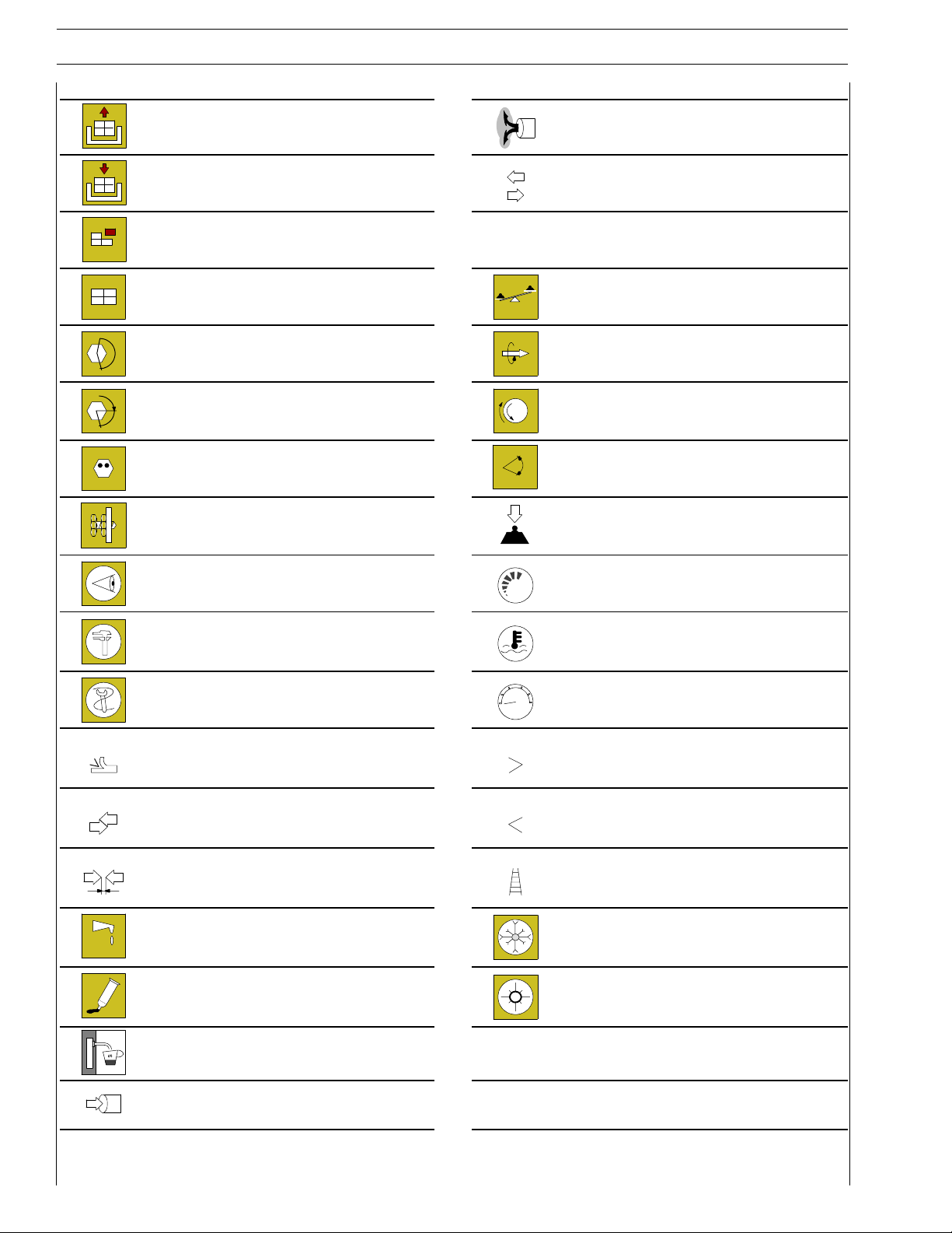
The manual uses proper symbols in its descriptions; the purpose of these symbols is to classify contained i nformation. In particular,
there have been defined a set of symbols to classify warnings and a set for assistance operations.
SYMBOLS - Warnings
Danger for persons
Missing or incomplete observance of these prescriptions can cause serious danger for persons’ safety.
Danger of serious damage for the assembly
Failure to comply, both fully or in part, with such prescriptions will involve serious damage to the assembly and may
sometimes cause the warranty to become null and void.
General danger
!
It includes the dangers of above described signals.
Environment protection
Moreover, it describes the correct actions to be taken to ensure that the assembly is used in such a way so as to protect
the environment as much as possible.
NOTE
It indicates an additional explanation for a piece of information.
Service operations
Example
∅
Ø 1 = Seat of small end bush
1
Close applying the required torque
Closeapplyingtherequiredtorque+angular
Ø 2 = Seat of connecting rod bearings.
∅
2
PrintP2D32F005 E Base - A
α
value
il 2009
Page 8
4
p
r
INTRODUCTION
F32 SERIES
Removal
Disconnection
Refitting
Connection
Removal
Disassembly
Fitting in place
Assembly
ρ
Exhaust
Operation
Compression ratio
Tolerance
Weight difference
Tighten to torque Rolling torque
Tighten to torque + angle value Rotation
α
Press or caulk
Regulation
Adjustment
Angle
Angular value
Preload
Visual inspection
Fitting position check
Measurement
Value to find
Check
Equipment
Surface for machining
Machine finish
Interference
Strained assembly
Thickness
Clearance
Lubrication
Damp
Grease
Sealant
Adhesive
bar
Number of revolutions
Temperature
Pressure
Oversized
Higher than….
Maximum, peak
Undersized
Less than….
Minimum
Selection
Classes
Oversizing
Temperature < 0 °C
Cold
Winter
Temperature > 0 °C
Hot
Summer
Air bleeding
Intake
Base - A
il 2009 PrintP2D32F005 E
Page 9

F32 SERIES
p
r
GENERAL WARNINGS
Warnings shown cannot be representative of all danger situations possibly occurring. Therefore, it is suggested to contact
immediate superiors where a danger situation occurs which is not described.
!
Use both specific and general-purpose toolings according to the prescriptions contained in respective use and
maintenance handbooks. Check use state and suitability of tools not subjected to regular check.
Manual handling of loads must be appraised beforehand, because this not only depends on the weight but also on the
size and path.
Handling with mechanical means must be done with lifters that are suitable for weight, shape and volume. Hoisters, ropes
and hooks used must contain clear indications on maximum carrying capacity acceptable. The use of said means is
compulsorily permitted to authorised personnel only. Stay duly clear of the load, and, anyhow, never under it.
In disassembling operations, always observe provided prescriptions; prevent mechanical parts being taken out from
accidentally striking workshop personnel.
Workshop jobs performed in pairs must always be performed in maximum safety; avoid operations which could be
dangerous for the c o-operator because of lack of visibility or of his/her not correct position.
Keep personnel not authorised to operations clear of working area.
You shall get familiar with the operating and safety instructions for the assembly prior to operating on the latter. Strictly
follow all the safety indications found on the assembly.
INTRODUCTION 5
Do not leave the running assembly unattended when making repairs.
When carrying out work on the assembly lifted off the ground, verify that the assembly is firmly placed on its supporting
stands, and that the manual/automatic safety devices have been actuated in the event that the assembly is to be lifted
by means of a hoist.
When you have to operate on assemblies powered by natural gas, follow the instructions contained in the document,
as well as all the specific safety standards provided for.
Only remove radiator cap when the engine is cold by cautiously unscrewing it in order to let system residual pressure
out.
Inflammable fuel and all inflammable fluids and liquids must be handled with care, according to what contained on harmful
materials 16-point cards. Refuelling must be performed outdoors with the engine off, avoiding lit cigarettes, free flames
or sparks in order to prevent sudden fires/bursts. Adequately store inflammable, corrosive and polluting fluids and liquids
according to what provided by regulations in force. Compulsorily avoid to use food containers to store harmful liquids.
Avoid to drill or bore pressurised containers, and throw cloths impregnated with inflammable substances into suitable
containers.
Worn out, damaged or consumable parts must be replaced by original spares.
During workshop activity, always keep the work place clean; timely clear or clean floors from accidental liquid or oil spots.
Electric sockets and electric equipment necessary to perform repair interventions must meet safety rules.
PrintP2D32F005 E Base - A
il 2009
Page 10

6
p
r
INTRODUCTION
F32 SERIES
Put on, where required by the intervention, garments and protections provided in accident prevention rules; contact
with moving parts can cause serious injuries. Use suitable, preferably tight-fitted garments, and avoid to use jewels,
scarves, etc.
Do not leave the engine in motion at workshop locations not provided with a pipe to scavenge exhaust gas outside.
Avoid to breathe fumes coming from heating or from paint welding because they can cause damages to health; operate
outdoors or in suitably ventilated areas. Put on proper inspirator if paint powder is present.
Avoid contact with hot water or steam coming from the engine, radiator and pipings because they could cause serious
burns. Avoid direct contact with liquids and fluids present in vehicle systems; where an accidental contact has occurred,
refer to 16-point cards for provisions to make.
Clean the assemblies and carefully verify that they are intact prior to overhauling. Tidy up detached or disassembled
parts with their securing elements (screws, nuts, etc.) into special containers.
Check for the integrity of the parts which prevent screws from being unscrewed: broken washers, dowels, clips, etc.
Self-locking nuts with an insert made of nylon must always be replaced.
Avoid contact of rubber parts with diesel oil, petrol or other not compatible substances.
Before washing under pressure mechanical parts, protect electric connectors, and central units, if present.
Tightening screws and nuts must always be according to prescriptions; FPT commercial and assistance network is
available to give all clarifications necessary to perform repair interventions not provided in this document.
Before welding:
- Disconnect all electronic central units, take power cable off battery positive terminal (connect it to chassis bonding)
and detach connectors.
- Remove paint by using proper solvents or paint removers and clean relevant surfices with soap and water.
- Await about 15 minutes before welding.
- Equip with suitable fire resistant protections to protect hoses or other components where fluids or other materials
flow which may catch fire easily on welding.
Should the vehicle be subjected to temperatures exceeding 80°C (dryer ovens), disassemble drive electronic central
units.
The disposal of all liquids and fluids must be performed with full observance of specific rules in force.
Base - A
il 2009 PrintP2D32F005 E
Page 11

F32 SERIES
p
r
GENERALWARNINGS ON THE ELECTRIC SYSTEM
If an intervention has to be made on the electric/electronic system, disconnect batteries from the system; in this case,
!
always disconnect, as a first one, the chassis bonding cable from batteries negative terminal.
Before connecting the batteries to the system, make sure that the system is well isolated.
Disconnect the external recharging apparatus from the public utility network before taking apparatus pins off battery
terminals.
Do not cause sparks to be generated in checking if the circuit is energised.
Do not use a test lamp in checking circuit continuity, but only use proper control apparatuses.
Make sure that the electronic devices wiring harnesses (length, lead type, location, strapping, connection to screening
braiding, bonding, etc.) comply with FPT system and are carefully recovered after repair or maintenance interventions.
Measurements in drive electronic central units, plugged connections and electric connections to components can only
be made on proper testing lines with special plugs and plug bushes. Never use improper means like wires, screwdrivers,
clips and the like in order to avoid the danger of causing a short circuit, as well as of damaging plugged connections, which
would later cause contact problems.
INTRODUCTION 7
To start up the engine, do not use fast chargers. Start up must only be performed with either separate batteries or special
truck.
A wrong polarisation of supply voltage in drive electronic central units (for instance, a wrong polarisation of batteries)
can cause them to be destroyed.
Disconnect the batteries from the system during their recharging with an external apparatus.
On connecting, only screw up connector (temperature sensors, pressure sensors etc.) nuts at prescribed tightening
torque.
Before disconnecting the junction connector from an electronic central unit, isolate the system.
Do not directly supply electronic central units servo components at nominal vehicle voltage.
Cables must be arranged such as to result to be parallel to reference plane, i.e. as close as possible to chassis/body
structure.
Once the intervention on the electric system has been completed, recover connectors and wiring harnesses according
to original arrangement.
NOTE
Connectors present must be seen from cable side. Connectors views contained i n the manual are representative of cable
side.
PrintP2D32F005 E Base - A
il 2009
Page 12
8
p
r
INTRODUCTION
F32 SERIES
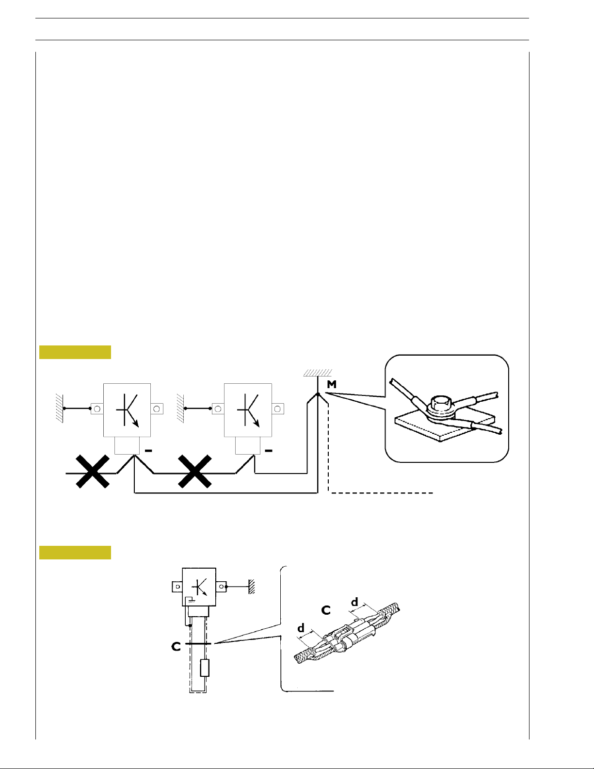
Bonding and screening
Negative leads connected to a system bonded point must be both as short and possible and “star“-connected to each other, trying
then to have their centering tidily and properly made (Figure 1, re. M).
Further, following warnings are to be compulsorily observed for electronic components:
- Electronic central units must be connected to system bonding when they are provided with a metallic shell.
- Electronic central units negative cables must be connected both to a system bonding point such as the dashboard opening
bonding (avoiding “serial“ or “chain“ connections), and to battery negative terminal.
- Analog bonding (sensors), although not connected to battery negative system/terminal bonding, must have optimal isolation.
Consequently, particularly considered must be parasitic resistances in lugs: oxidising, clinching defects, etc.
- Screened circuits braiding must only electrically contact the end towards the central unit entered by the signal (Figure 2).
- If junction connectors are present, unscreened section d, near them, must be as short as possible (Figure 2).
- Cables must be arranged such as to result to be parallel to reference plane, i.e. as close as possible to chassis/body structure.
Figure 1
1. NEGATIVE CABLES “STAR“ CONNECTION TO SYSTEM BONDING M
Figure 2
88039
2. SCREENING THROUGH METALLIC BRAIDING OF A CABLE TO AN ELECTRONIC COMPONENT — C. CONNECTOR
d. DISTANCE ! 0
Base - A
il 2009 PrintP2D32F005 E
Page 13

F32 SERIES
p
r
INTRODUCTION 9
CONVERSIONS BETWEEN THE MAIN UNITS OF MEASUREMENT OF THE INTERNATIONAL SYSTEM AND MOST USED DERIVED QUANTITIES
Power
1 kW = 1.36 metric HP
1 kW = 1.34 HP
1 metric HP = 0.736 kW
1 metric HP = 0.986 HP
1 HP = 0.746 kW
1 HP = 1.014 metric HP
Torque
1 Nm = 0.1019 kgm
1 kgm = 9.81 Nm
Revolutions per time unit
1 rad/s = 1 rpm x 0.1046
1 rpm = 1 rad/s x 9.5602
Pressure
Pa
2
2
according to ratio 1:1
1 bar = 1.02 kg/cm
1 kg/cm
1bar = 10
2
= 0.981 bar
5
Where accuracy is not particularly needed:
- Nm unit is for the sake of simplicity converted into kgm according to ratio 10:1
1 kgm = 10 Nm;
- bar unit is for the sake of simplicity converted into kg/cm
2
1 kg/cm
=1bar.
Temperature
0° C=32° F
1° C = (1 x 1.8 + 32) ° F
PrintP2D32F005 E Base - A
il 2009
Page 14
10
p
r
INTRODUCTION
KEY OF LECTURE OF THE HEADINGS AND FOOTNOTES
F32 SERIES
Type of
vehicle
Section
title
Page
number
Printout
number
Base - A
il 2009 PrintP2D32F005 E
Language
Publication
Basic edition referred to
month - year editorial
phase closing
When month - year update
is present (revi) to the basic
edition
Page 15

F32 SERIES
p
r
1
Part 1
F32 SERIES
Section
General specifications
Fuel 2
Industrial application 3
Overhaul and technical specifications 4
Tools 5
Safety prescriptions Appendix
1
PrintP2D32F005 E Base - A
il 2009
Page 16

2
p
r
F32 SERIES
Base - A
il 2009 PrintP2D32F005 E
Page 17

F32 SERIES
UPDATING
Section Description Page Date of revision
3
3
4
Industrial application
Mechanical overhaul
21, 64
30, 31, 32, 33
January 2010
April 2012
Print P2D32F005 E Base - April 2009
Revi 04.2012
Page 18

4
p
r
F32 SERIES
Base - A
il 2009 PrintP2D32F005 E
Page 19

F32 SERIES
p
r
SECTION 1 - GENERAL SPECIFICATIONS 1
SECTION 1
General specifications
Page
CORRESPONDENCY BETWEEN TECHNICAL
CODING AND COMMERCIAL CODING 3....
ENGINE VIEWS
(for F5CE9454E*A005, F5CE9484D*A002 engines) 4..
ENGINE VIEWS
(for F5CE5454B*A004 engines) 5.............
ENGINE LUBRICATION SYSTEM 6.............
- Oil pump 7.............................
- Engine oil filter 8.........................
ENGINE OIL VAPOUR RECIRCULATION 9......
ENGINE COOLING SYSTEM 10.................
- For engines without external EGR 10..........
- For engines with external EGR 11............
WATER PUMP 12............................
THERMOSTAT 12............................
- Working system 12........................
HEAT EXCHANGER 13.......................
EGR EXHAUST GAS RECYCLE SYSTEM 14........
- Internal EGR operating on the intake valves
(for F5CE9454, F5CE9484 engines) 14.........
- Intake cam profile 14......................
- External E.G.R. system
(for F5CE5454 engines) 15..................
- Working system 15........................
BOOSTING 16..............................
- For engines without external EGR 16..........
- For engines with external EGR 17............
PrintP2D32F005 E Base - A
il 2009
Page 20

2
p
r
SECTION 1 - GENERAL SPECIFICATIONS
F32 SERIES
Base - A
il 2009 PrintP2D32F005 E
Page 21

F32 SERIES
p
r
F32MN
S.X
SECTION 1 - GENERAL SPECIFICATIONS 3
CORRESPONDENCY BETWEEN TECHNICAL CODING AND COMMERCIAL CODING
Technical Code Commercial Code
F5CE5454B*A004
F5CE9454E*A005
F5CE9484D*A002 F32 MNT.X
PrintP2D32F005 E Base - A
il 2009
Page 22
4
p
r
SECTION 1 - GENERAL SPECIFICATIONS
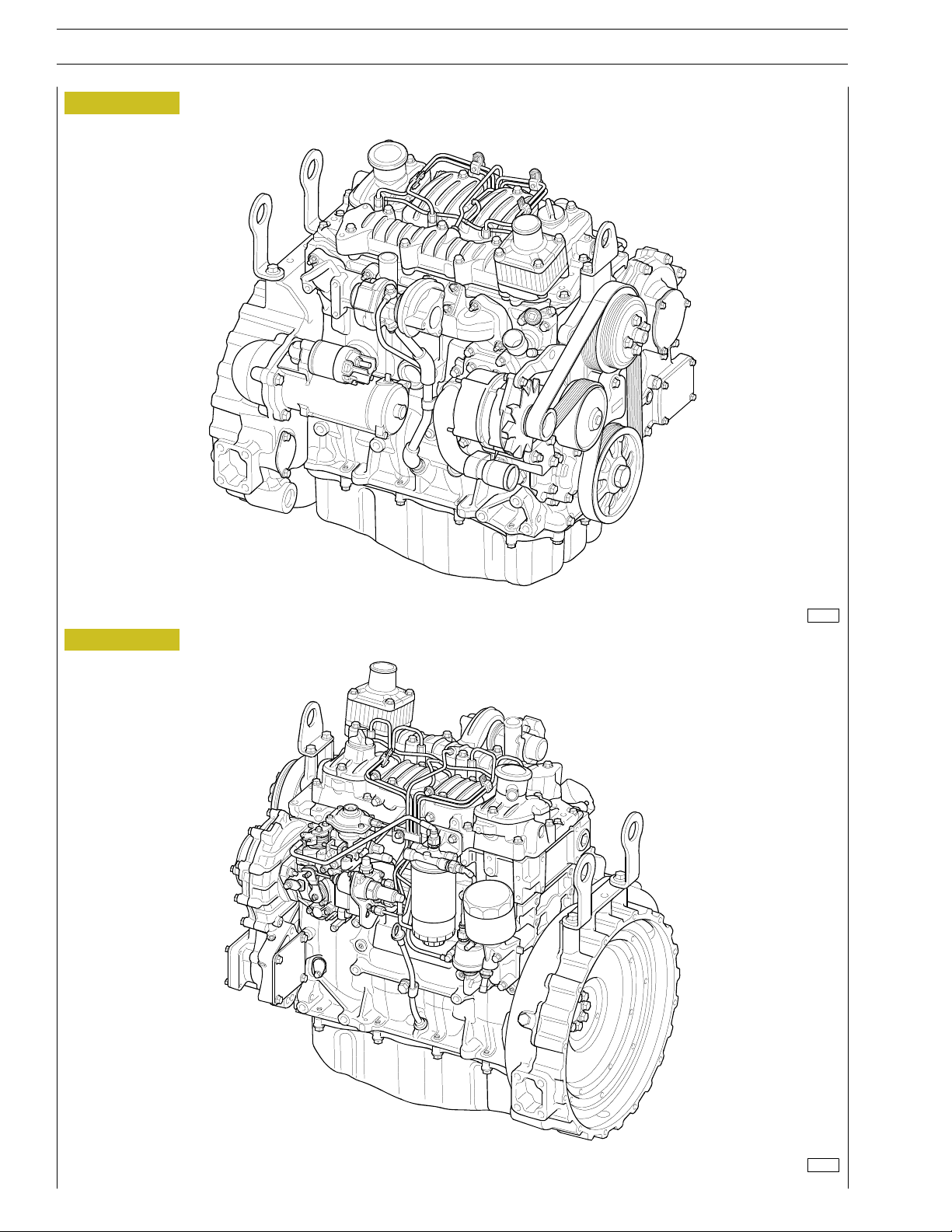
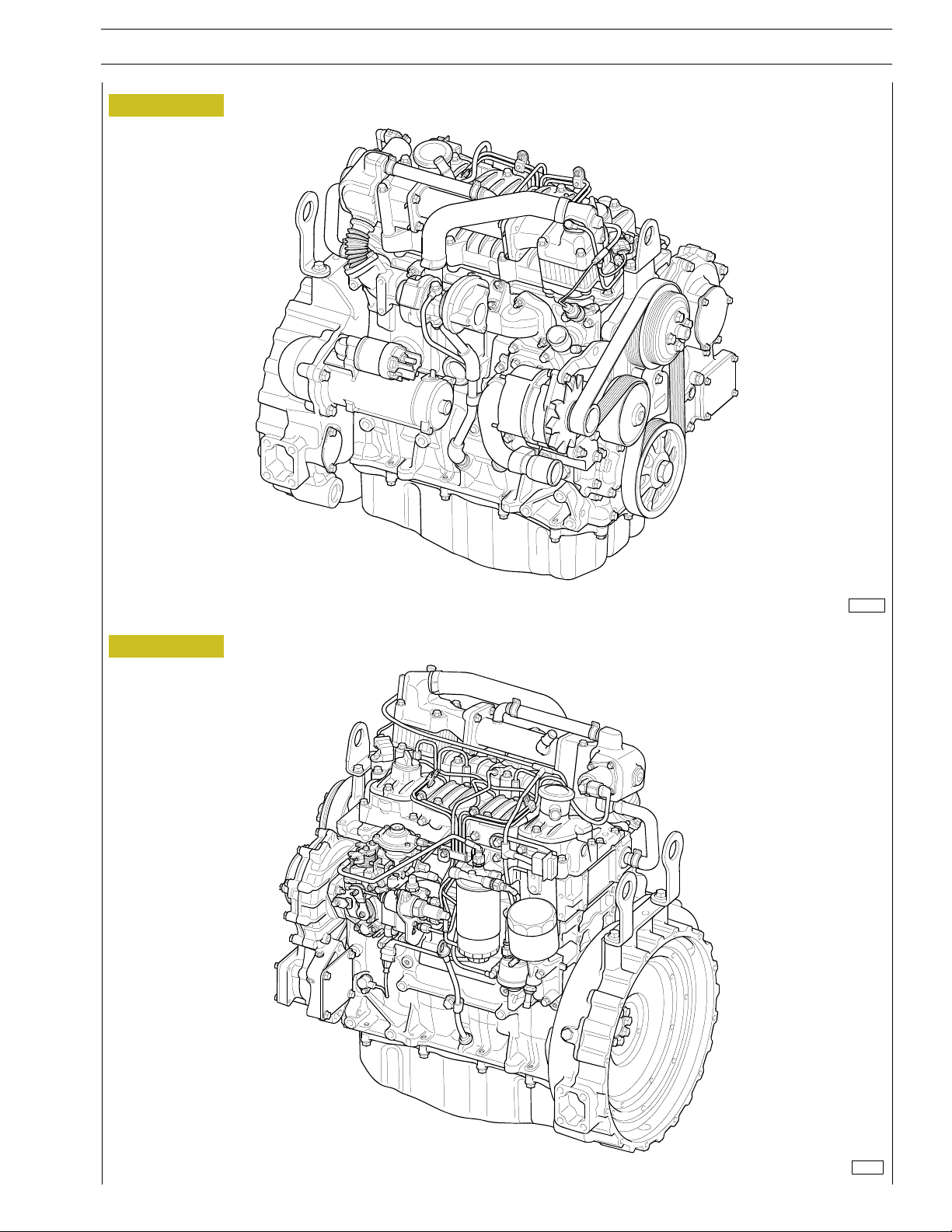
ENGINE VIEWS (for F5CE9454E*A005, F5CE9484D*A002 engines)
Figure 1
F32 SERIES
Figure 2
128134
128135
Base - A
il 2009 PrintP2D32F005 E
Page 23
F32 SERIES
p
r
ENGINE VIEWS (for F5CE5454B*A004 engines)
Figure 3
SECTION 1 - GENERAL SPECIFICATIONS 5
Figure 4
128136
128137
PrintP2D32F005 E Base - A
il 2009
Page 24
6
p
r
SECTION 1 - GENERAL SPECIFICATIONS
F32 SERIES
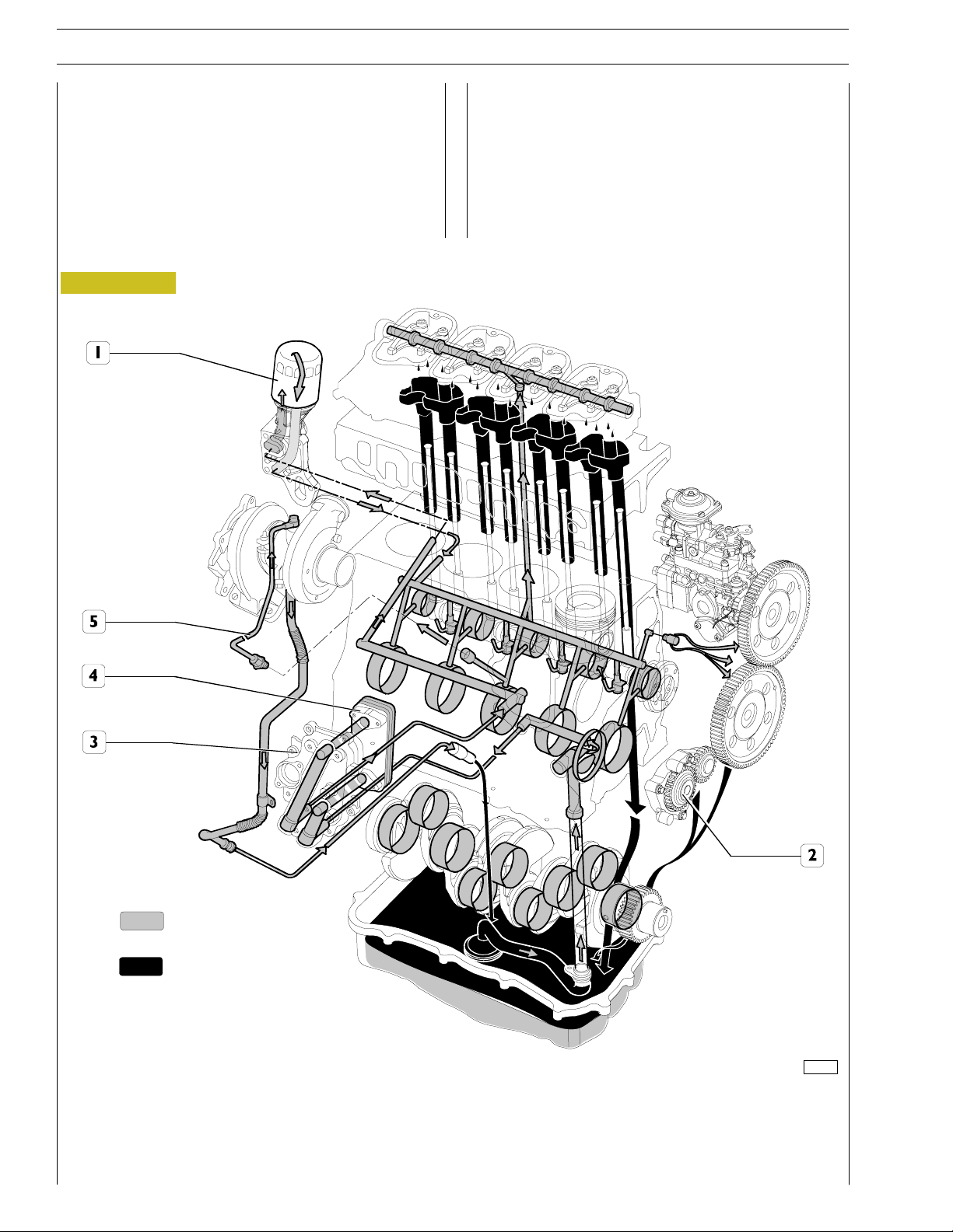
ENGINE LUBRICATION SYSTEM
Forced circulation lubrication is controlled by the rotor oil
pump housed in the front part of the engine basement and
driven by the toothed gear splined on the shank of the engine
drive shaft.
From the oil pan, the lubrication oil is distributed to the engine
drive shaft, the camshaft and the valve control.
Figure 5
The lubrication system also comprises the heat exchanger, he
centrifugal blower for the versions with turbosupercharger
and eventually the compressor if the compressed air system
is also fitted.
All the above mentioned components vary depending on their
use and therefore will be illustrated in the specific section.
Pressurized oil
Dropping oil
127695
LUBRICATION SYSTEM DIAGRAM
1. Oil filter - 2. Oil pump - 3. Heat exchanging unit - 4. Heat exchanger -
5. Turbosupercharger lubrication feed pipe
Base - A
il 2009 PrintP2D32F005 E
Page 25
F32 SERIES
p
r
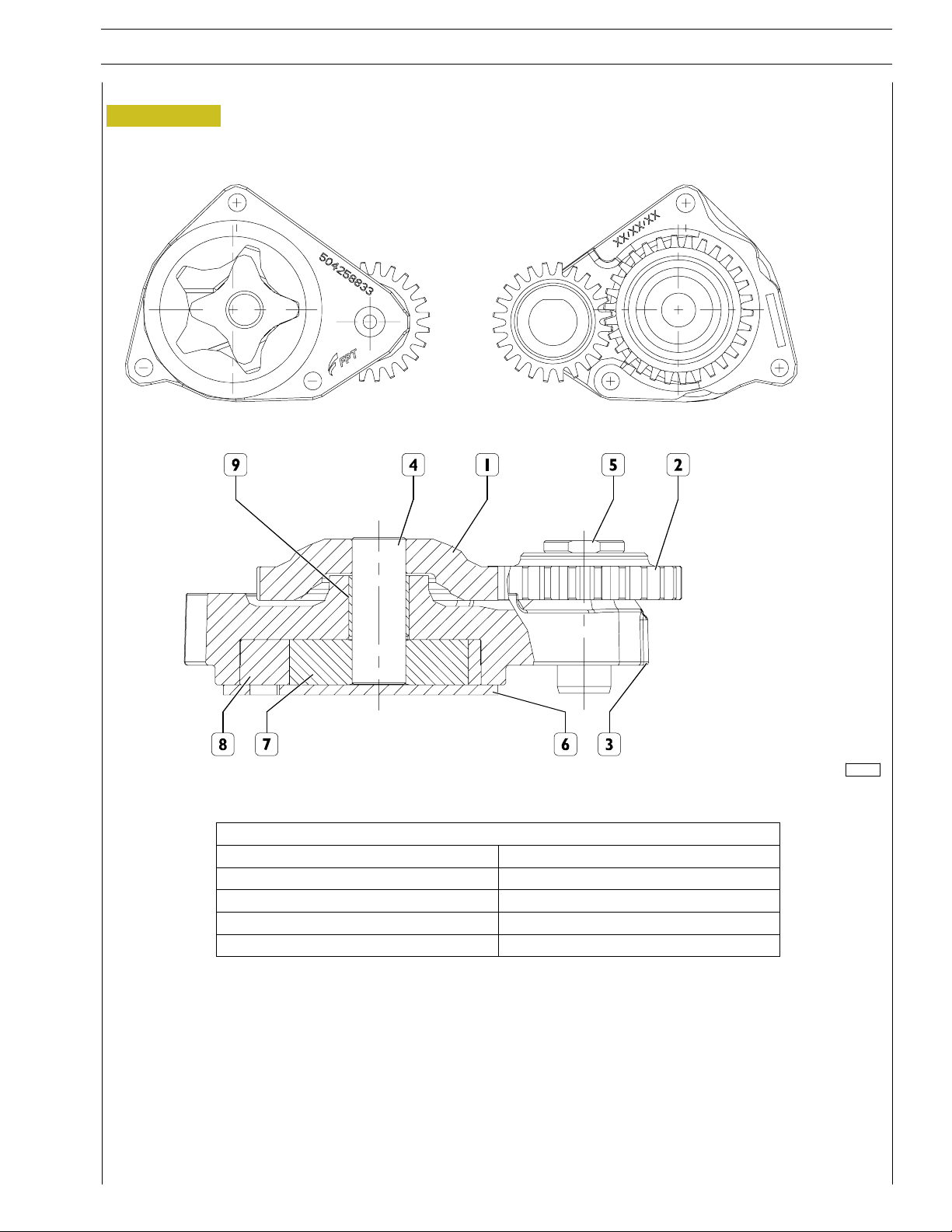
Oil pump
Figure 6
SECTION 1 - GENERAL SPECIFICATIONS 7
119405
PUMP SPECIFICATIONS
Rotating speed 750 rpm - 4200 rpm
Feed pressure 2Bar-4Bar
Rated flow 12.2 l/min - 75.9 l/min
Oil type SAE 20/30
Max. oil temperature 80 °C
1. Main gear - 2. Secondary gear - 3. Pump unit - 4. Drive shaft - 5. Secondary shaft
6. Cover - 7. Internal rotor - 8. External rotor - 9. Bush.
PrintP2D32F005 E Base - A
il 2009
Page 26
8
p
r
SECTION 1 - GENERAL SPECIFICATIONS
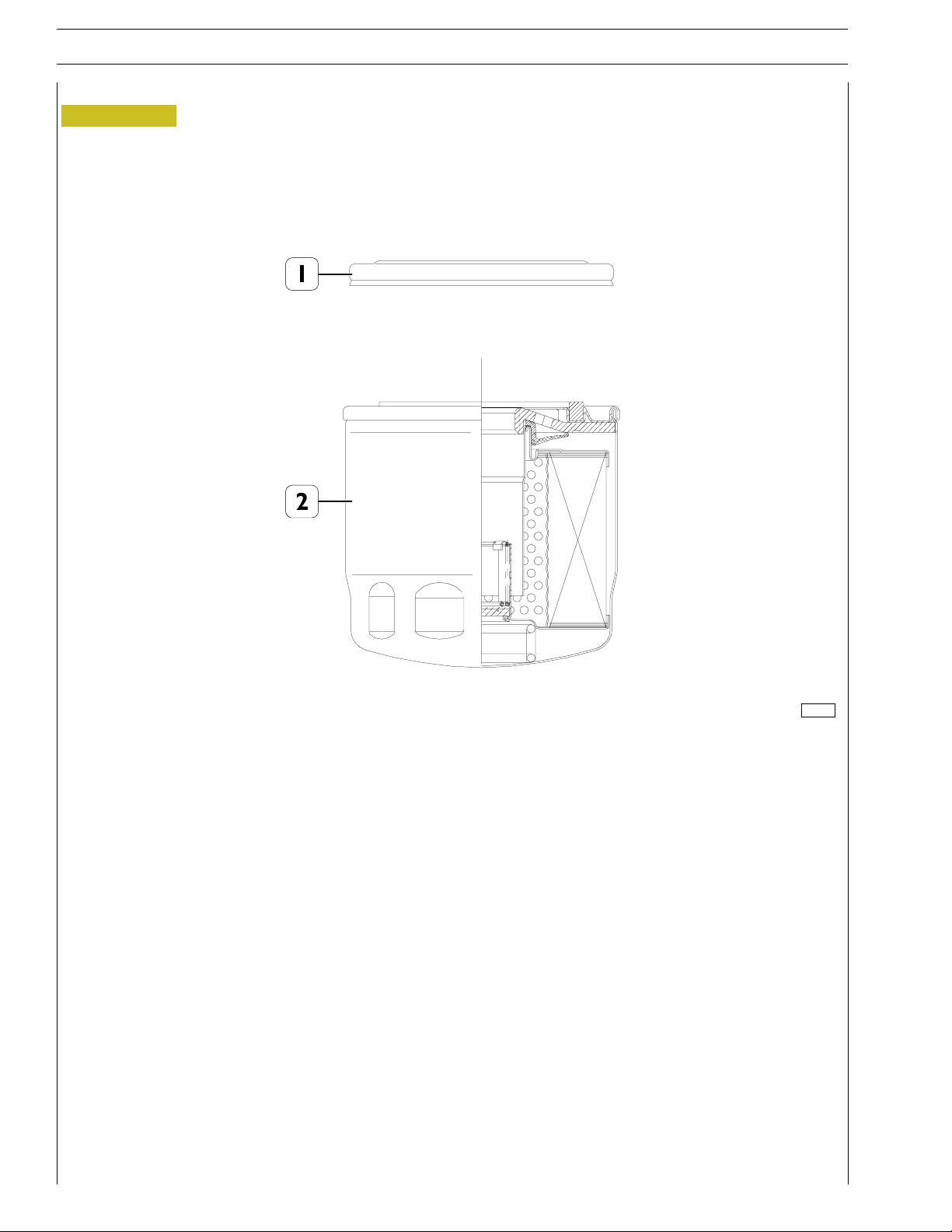
Engine oil filter
Figure 7
F32 SERIES
1. Protective cover - 2. Cartridge
Booster pressure: 20 bar (ISO 4548/3)
Dynamic pressure: 0-15 bar (1Hz) > 50,000 cycles (ISO 4548/5)
Operating temperature: -40 / + 140 ˚C
Torque wrench setting: 32.5 ± 2.5 Nm
Maximum flow: 50 l/min.
Load loss at the end of life cycle: 2.5 bar
Accumulation: > 15 gr with 2.5 bar load loss (ISO 16889)
119406
Base - A
il 2009 PrintP2D32F005 E
Page 27
F32 SERIES
p
r
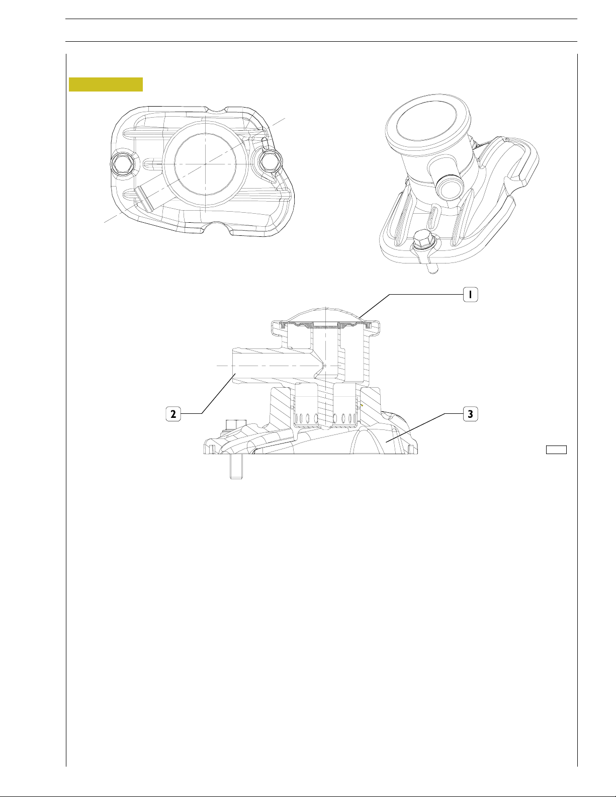
ENGINE OIL VAPOUR RECIRCULATION
Figure 8
SECTION 1 - GENERAL SPECIFICATIONS 9
119407
1. Valve - 2. Breather - 3. Tappet cover
On the tappet cover (3) there is a valve (1) having the duty to cause condensation of oil vapours making them drop by gravity
on the underlying tappet cover (3).
The remaining non condensed vapours will be duly conveyed through the breather (2), for instance by suction (appropriate
connection must be provided by the outfitter).
PrintP2D32F005 E Base - A
il 2009
Page 28
10
p
r
SECTION 1 - GENERAL SPECIFICATIONS
F32 SERIES
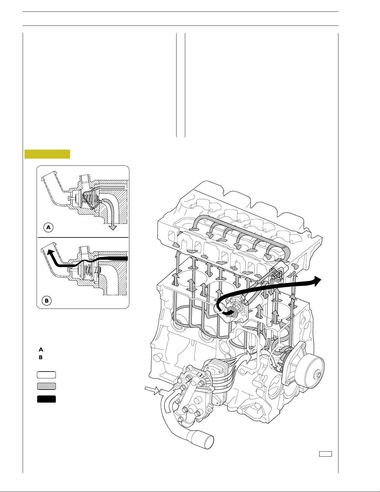
ENGINE COOLING SYSTEM
For engines without external EGR
The closed circuit forced circulation engine cooling system is
composed of the following parts:
- expansion tank: position, form and dimensions may vary
depending on the engine fitting;
- radiator dissipating the heat absorbed by the engine
cooling liquid. This component’s position and dimensions
may vary depending on the outfit;
- fan increasing the radiator’s cooling power. This
component may vary depending on the specific engine
fitting;
Figure 9
- heat exchanger coolingthe lubricant oil. This component
may vary depending on the specific engine fitting;
- centrifugal water pump positioned in the front part of the
engine basement;
- thermostat controlling cooling liquid circulation.
Closed thermostat
Open thermostat
Water inflow
Engine cooling water
Water outflow from thermostat
120018
ENGINE COOLING SYSTEM DIAGRAM
Base - A
il 2009 PrintP2D32F005 E
Page 29
F32 SERIES
p
r
SECTION 1 - GENERAL SPECIFICATIONS 11
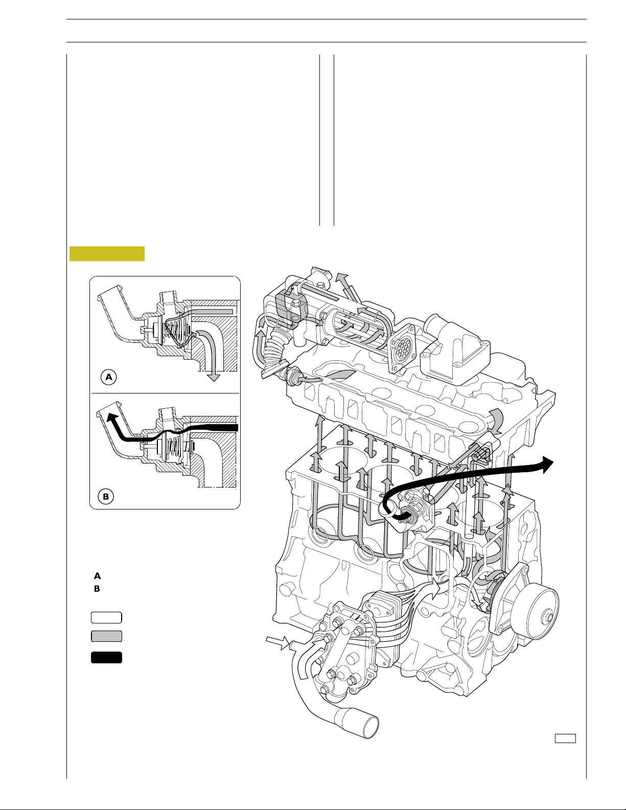
For engines with external EGR
The closed circuit forced circulation engine cooling system is
composed of the following parts:
- expansion tank: position, form and dimensions may vary
depending on the engine fitting;
- radiator dissipating the heat absorbed by the engine
cooling liquid. This component’s position and dimensions
may vary depending on the outfit;
- fan increasing the radiator’s cooling power. This
component may vary depending on the specific engine
fitting;
Figure 10
- heat exchanger coolingthe lubricant oil. This component
may vary depending on the specific engine fitting;
- centrifugal water pump positioned in the front part of the
engine basement;
- thermostat controlling cooling liquid circulation.
Closed thermostat
Open thermostat
Water inflow
Engine cooling water
Water outflow from thermostat
118983
ENGINE COOLING SYSTEM DIAGRAM
PrintP2D32F005 E Base - A
il 2009
Page 30
W
12
p
r
SECTION 1 - GENERAL SPECIFICATIONS
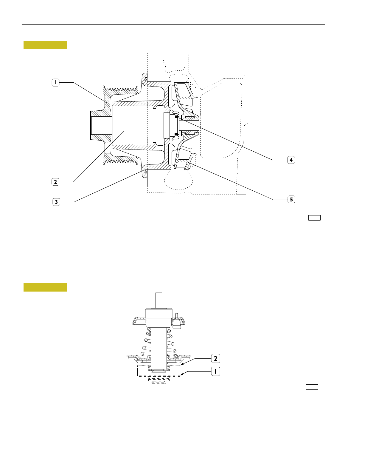
ATERPUMP
Figure 11
F32 SERIES
120047
WATER PUMP SECTION
1. Hub - 2. Shaft with bearing - 3. Pump unit - 4. Sheath - 5 . Impeller.
The water pump is a centrifugal blade turbine type pump. The pump’s bearing (2) is connected to the impeller’s shaft as a whole.
Water tight between the pump unit (3) and the shaft (2) is ensured by the sheath (4).
THERMOSTAT
Figure 12
119412
THERMOSTAT DIAGRAM
Working system
When the engine is cool, water output from the front part of the cylinder head flows into an inlet containing the thermostat, which
cuts out water circulation to the radiator. This way, water circulation will only be possible in the pump-enginecircuit, insofar allowing
engine heat-up quickly. The thermostat valve starts opening at nearly 80 ˚C, allowing water circulation into the radiator and also
obstructing direct return towards the engine. Check the thermostat efficiency and replace it in case of doubtful functioning.
1. Stroke starts at 79˚ ±2˚C
2. 7 mm stroke at 94˚±2˚C
Base - A
il 2009 PrintP2D32F005 E
Page 31

R
F32 SERIES
p
r
HEAT EXCHANGE
Figure 13
SECTION 1 - GENERAL SPECIFICATIONS 13
SECTION A-A
SECTION B-B
119408
The heat exchanger within the engine cooling system has the duty to control the engine oil temperature, reducing it by absorbing
heat throughout the engine cooling liquid.
PrintP2D32F005 E Base - A
il 2009
Page 32

14
p
r
SECTION 1 - GENERAL SPECIFICATIONS
F32 SERIES
EGR EXHAUST GAS RECYCLE SYSTEM
The exhaust gas can be partially recycled to cylinders to reduce maximum temperature values of combustion that produce nitrogen
oxides (NOx).
The exhaust gas recycle system (EGR) reduces combustion temperature and therefore is an efficient NOx emission control system.
Internal EGR operating on the intake valves (for F5CE9454, F5CE9484 engines)
The specific design of suction cams of the internal EGR system allows part of exhaust gas to be recycled to engine cylinders.
This type of EGR, called internal EGR, is not equipped with any electronic control, the system is always active. Its configuration
requires no additional parts such as control valves, pipelines or heat exchangers therefore engine profile remains unchanged
Besides main lobe, suction cam has an additional lobe as to configuration without EGR. During concerned cylinder exhaust phase,
this lobe allows a shaft advanced opening of intake valve (*). In this way, part of the exhaust gas is trapped in the suction duct and
later, during cylinder suction phase, this gas is recycled to cylinder inlet for combustion phase..
Intake cam profile
Figure 14
*
122430
X. Cam rotation angle (degrees) - Y. Cam lift mm
Base - A
il 2009 PrintP2D32F005 E
Page 33

(
f
)
F32 SERIES
p
r
SECTION 1 - GENERAL SPECIFICATIONS 15
External E.G.R.system
Figure 15
or F5CE5454 engines
119409
1. Valve unit - 2. Heat exchanger - 3. Water pipe - 4. Exhaust gas pipe - 5. Intake manifold
6. Exhaust manifold - 7. Engine head.
Working system
The EGR system fitted in between the exhaust manifold and the intake manifold allows partial exhaust gas recovery into the engine
cylinders after having been cooled throughout a heat exchanger. This way the combustion temperature maximum values,
responsible of the formation of Nitrogen oxides (NOx) can be reduced. Hence, reducing the aforesaid temperatures by decreasing
the concentration of oxygen in the combustion chamber, the EGR system efficiently controls NOx emissions.
As shown in the figure, throughout pipe (4) the exhaust gas will be conveyed through the exhaust manifold to the valve unit (1).
If the control unit enables the valve, the exhaust gas will be conveyed to the heat exchanger (2) where it will be cooled throughout
the engine cooling liquid system which controls the cooling liquid recirculation through the water pipe (3) and the valve unit (1)
(cooling the valve as well) from the engine head to the heat exchanger. The cooled exhaust gas will be further conveyed from the
heat exchanger to the intake manifold.
PrintP2D32F005 E Base - A
il 2009
Page 34

16
p
r
SECTION 1 - GENERAL SPECIFICATIONS
BOOSTING
For engines without external EGR
The boosting system is composed of the following parts:
- Air filter;
- Turbosupercharger.
- An ”intercooler” radiator (if fitted)
Figure 16
F32 SERIES
124466
Sucked air
Heated compressed air
Engine exhaust gas
Base - A
il 2009 PrintP2D32F005 E
Page 35

F32 SERIES
p
r
For engines with external EGR
The boosting system is composed of the following parts:
- Air filter;
- Turbosupercharger.
Figure 17
SECTION 1 - GENERAL SPECIFICATIONS 17
EGR closed valve
EGR open valve
Sucked air
Heated compressed air
Engine exhaust gas
Exhaust gas recirculation
127696
PrintP2D32F005 E Base - A
il 2009
Page 36

18
p
r
SECTION 1 - GENERAL SPECIFICATIONS
F32 SERIES
Base - A
il 2009 PrintP2D32F005 E
Page 37

F32 SERIES
p
r
SECTION 2 - SUPPLY 1
SECTION 2
Supply
Page
SUPPLY 3.................................
PIPE LAYOUT 4............................
- Working System Description 5.............
SUPPLY PUMP 6............................
- Identification coding example 6.............
WORKING SYSTEM DESCRIPTION 7...........
- Supply Phase 7..........................
- Delivery Phase 7.........................
- End of Delivery Phase 8...................
- Engine Stop 8...........................
- L.D.A. Load Delivery Adjustment device 9.....
- Working System 9.......................
PRIMING PUMP 10...........................
FUEL FILTER 11.............................
PrintP2D32F005 E Base - A
il 2009
Page 38

2
p
r
SECTION 2 - SUPPLY
F32 SERIES
Base - A
il 2009 PrintP2D32F005 E
Page 39

F32 SERIES
p
r
SUPPLY
The engine supply system consists of the following components:
- Fuel tank (aboard the vehicle)
- Fuel delivery and return pipes
- Fuel pre-filter (if fitted, it is placed nearby the engine on the vehicle’s chassis)
- Priming pump, fitted on the engine and driver by the engine camshaft
- Fuel filter (its position on the engine may vary depending on the outfit and use)
- Supplyrotarypump
- Injector feed pipe (from the fuel supply pump to the fuel injectors)
- Injectors
Figure 1
SECTION 2 - SUPPLY
3
119420
SUPPLY SYSTEM DIAGRAM
1. Injectors - 2. Fuel filter - 3. Tank - 4. Supply rotary pump - 5. Ignition pump.
PrintP2D32F005 E Base - A
il 2009
Page 40

4
p
r
SECTION 2 - SUPPLY
PIPE LAYOUT
Figure 2
F32 SERIES
118976
1. Injector feed pipe - 2. Fuel exhaust pipe from injectors - 3. Supply rotary pump - 4. Union for pressure gauge pipe within
LDA intake manifold - 5. KSB thermal bulb - 6. Solenoid valve - 7. Injector.
Base - A
il 2009 PrintP2D32F005 E
Page 41

F32 SERIES
p
r
Figure 3
SECTION 2 - SUPPLY
5
Working system description
The fuel (5) is primed from the fuel tank from the priming
pump (6). The latter is fitted on the engine basement and is
driven by the engine camshaft.
Throughout the filter (4), fuel is conveyed to the transfer
pump, which is placed inside the supply rotary pump (2),
which is a turbine blade pump type. The supply rotary pump
duty is to increase the fuel pressure based on the increase of
engine revolutions’ number.
119961
Then, the fuel reach es the valve con trolling fuel pressure with in
the supply pump.
The distributor piston further inc reases such pressure and
delivers the fuel to the injectors (1) throughout the delivery
pipe fitting.
The fuel leak (3) from the injectors is recovered and sent back
to the fuel tank.
PrintP2D32F005 E Base - A
il 2009
Page 42

6
p
r
SECTION 2 - SUPPLY
SUPPLY PUMP
The rotary type supply pump is driven by a gear which is coupled to the en gine camshaft gear.
Identification coding example
V = rotary distributor piston pump
E = pump dimensions
4 = four cylinder engines
12 = distributor piston size in mm
1150 = no. of pump rev./min.
RV = right direction rotation
Figure 4
F32 SERIES
1
15
2
14
3
4
5
13
12
6
7
8
9
11
10
30454
Ignition pump longitudinal section
1. Membrane - 2. Setting ring - 3. Feeler pin - 4. Drive lever - 5. Speed regulator - 6. Transfer pump - 7. Drive shaft -
8. Cam disk - 9. Spark lead adjuster - 10. Distributor piston - 11. Feed pipe fitting - 12. Hydraulic head - 13. Control plate -
14. Adjusting pin - 15. Counter spring.
Base - A
il 2009 PrintP2D32F005 E
Page 43

F32 SERIES
p
r
WORKING SYSTEM DESCRIPTION
Supply phase
Figure 5
SECTION 2 - SUPPLY
7
119415
1. Fuel supply pipe - 2. Solenoid valve - 3. Axial groove - 4. Compression chamber - 5. Fuel delivery pipe from pump to
injectors - 6. Distributor piston - 7. End of delivery port - 8. Cursor - 9. Injector.
The distributor piston (6) is at B.D.C. and the cursor (8) closes the delivery port (7). The fuel is delivered to the compression
chamber (4) through the feed pipe (1) which is kept open by the solenoid valve (2).
Delivery phase
Figure 6
119416
1. Fuel feed pipe - 2. Compression chamber - 3. Distributor piston inner pipe
4. Fuel delivery pipe from pump to injec tor - 5. Distributor piston - 6. Injector.
The distributor piston (5) driven by the cam disk, goes up to the T.D.C. and simultaneously rotates on its own axle. The
combination of the two motions determines the closure of the fuel feed pipe (1) as well as the fuel compression within the
chamber (2). The distributor piston inner pipe (5) is connected to the feed pipe (4) thus enabling fuel delivery to the injectors
(6).
PrintP2D32F005 E Base - A
il 2009
Page 44

8
p
r
SECTION 2 - SUPPLY
End of delivery phase
Figure 7
F32 SERIES
119417
1. Fuel feed pipe - 2. Compression chamber - 3. Fuel delivery pipe - 4. End of delivery pipe -
5. Cursor - 6. Distributor piston.
The distributor piston (6) moving towards the T.D.C. connects the high pressure inner chamber to the pipe (1), thereby
establishing pressure balance between the distributor piston inner chamber, the injectors’ delivery pipe and the pump interior.
Since such pressure is lower than the one required to start the injector, end of delivery will be determined.
Engine stop
Figure 8
119418
1. Fuel feed pipe - 2. Mobile cap - 3. Spring - 4. Solenoid valve - 5. Compression chamber.
Engine stop is provoked cutting out the starter contact.
The electric flux to the solenoid valve (4) is c ut out. The solenoid valve, throughout its spring (3), drives the mobile cap to the
end of stroke (2) and the mobile cap obstructs the fuel feed pipe (1).
Base - A
il 2009 PrintP2D32F005 E
Page 45

F32 SERIES
p
r
L.D.A. Load Delivery Adjustment device
Figure 9
SECTION 2 - SUPPLY
9
119419
Working system
The duty of the L.D.A. device is to adjust the fuel delivery depending on the air pressure within the intake manifold.
Air pressure acts on the membrane (1), which is tied up to the setting pin (4). In the lower part of the setting pin (4) there is
a conical hou sing (5) in which the feeling pin runs (6).
The setting pin (4) axial motion drives the feeling pin (6) shift and the latter acts on th e stop lever (7). The stop lever rotates
on its own axle (8) and acts on the control plate in order to adjust the fuel delivery depending on the air quantity within the
cylinders.
PrintP2D32F005 E Base - A
il 2009
Page 46

10
p
r
SECTION 2 - SUPPLY
F32 SERIES
PRIMING PUMP
The primingpump duty is to prime the fuel from the tank and convey it to the fuel supply pump. It is fitted on the engine basement
and driven by the engine camsh aft.
Figure 10
1. Pump - 2. Control lever - 3. Camshaft.
88209
Base - A
il 2009 PrintP2D32F005 E
Page 47

F32 SERIES
p
r
SECTION 2 - SUPPLY
FUEL FILTER
The filter is placed nearby the supply pump and the priming pump. Its duty is to retain impurities and separate water from the
fuel in which it is contained.
At th e bottom of th e filtering cartridge there may be a water drainage device (3).
Figure 11
11
119411
1. Fuel filter support - 2. Cartridge filter- 3. Water drainage device
PrintP2D32F005 E Base - A
il 2009
Page 48

12
p
r
SECTION 2 - SUPPLY
F32 SERIES
Base - A
il 2009 PrintP2D32F005 E
Page 49

F32 SERIES
p
r
SECTION 3 - INDUSTRIAL APPLICATION
SECTION 3
Industrial application
MAIN SPECIFICATIONS 3..................
PART ONE -
MECHANICAL COMPONENTS 5.........
ENGINE DISASSEMBLY ON BENCH 7........
- Cylinder 1 T.D.C. search 8.................
- BOSCH VE 4/12F Pump 9.................
- Timing gearcase 12........................
- Rear side co mponent assembly 14...........
- Flywheel assembly 14......................
1
Page
- Front side component installation 15..........
- Timing 16...............................
- Piston projection measurement 17...........
- Checks and inspections 25..................
- Rocker cover blow-by removal and refitting 26..
- Rotary feed pump disassembly and assembly
procedure 30............................
- Injection pump static advance control on engine at
cylinder 1 TDC 33........................
- Power takeoff 33.........................
PART TWO - ELECTRICAL EQUIPMENT 35...
ENGINE CABLE FOR EXTERNAL EGR SYSTEM
(FOR F5CE5454 ENGINES) 37..............
EXTERNAL EGR E.C.U. ELECTRICAL LAYOUT
(FOR F5CE5454 ENGINES) 38..............
- External EGR E.C.U.
(for F5CE5454 engines) 39.................
- Pin out EGR E.C.U. 40.....................
KSB - BOSCH PUMP CONNECTION CABLE 41.
PrintP2D32F005 E Base - A
il 2009
Page 50

2
p
r
SECTION 3 - INDUSTRIAL APPLICATION
Page
- E n gine cooling liquid temperature sensor
(for F5CE5454 engines) 42.................
- O il pressure switch 43.....................
- Cooling liquid temperature sensor for KSB 44...
- Air pressure temperature sensor
(for F5CE5454 engines) 45.................
- Engine drive shaft sensor (for F5CE5454 engines) 46
- EGR Solenoid valve (for F5CE5454 engines) 47.
- Delivery specifications 47...................
- Starter 48...............................
- BOSCH 14V Alternator 49.................
PART THREE - TROUBLESHOOTING 51.......
DIAGNOSIS BY FAILURE 53..................
F32 SERIES
PART FOUR - MAINTENANCE PLANNING 59..
SCHEDULED MAINTENANCE 61.............
- Servicing Plan 61.........................
- Overhaul and/or basic maintenance 61........
- Checks not included in maintenance planning-daily
checks 62...............................
MAINTENANCE PROCEDURES 62............
- Chec ks and controls 62....................
Base - A
il 2009 PrintP2D32F005 E
Page 51

F32 SERIES
p
r
MAIN SPECIFICATIONS
Type F5CE9454E*A005 F5CE5454B*A004 F5CE9484D*A002
Cycle Diesel 4 strokes
Feeding Turbocharged
Injection Direct
N. of cylinders 4 on-line
∅
Diameter mm 99
Stroke mm 104
SECTION 3 - INDUSTRIAL APPLICATION 3
Turbocharged
Turbocharged -
intercooler
+++..=
ρ
Total displacement cm
Compression ratio
Max. power kW
Max. power Nm
Loadless engine
idling rpm
Loadless engine
peak rpm
EGR Internal External Internal
COOLING
Water pump contr ol
Thermostat
- start of opening ºC
3
3200
17 ± 0.5 : 1
(HP)
55
(75)
61
(83)
rpm 2500 2500 2300
(kgm)
281
(29)
310
(32)
rpm 1250 1250 1400
750 750 750
3000 3000 3000
Liquid
Through belt
79 ± 2
65
(88)
340
(35)
OIL SUPPLY
NOTE
Total quantity l
st
1
SAE 15W40 T2
URANIA LD7
filling (kg)
MIN level l
(engine off) (kg)
MAX level l
(engine off) (kg)
Data, features and performances are valid only if the setter fully complies with all the installation prescriptions provided
10.5
(9.2)
7.5
(6.6)
9.5
(8.4)
by FPT.
Furthermore, the users assembled by the setter shall always be in conformance to couple, power and number of turns
based on which the engine has been designed.
PrintP2D32F005 E Base - A
il 2009
Page 52

4
p
r
SECTION 3 - INDUSTRIAL APPLICATION
F32 SERIES
Base - A
il 2009 PrintP2D32F005 E
Page 53

F32 SERIES
p
r
DIAGNOSI
SECTION 3 - INDUSTRIAL APPLICATION 5
PART ONE - MECHANICAL COMPONENTS
PrintP2D32F005 E Base - A
il 2009
Page 54

6
p
r
SECTION 3 - INDUSTRIAL APPLICATION
F32 SERIES
Base - A
il 2009 PrintP2D32F005 E
Page 55

F32 SERIES
p
r
zl
SECTION 3 - INDUSTRIAL APPLICATION
7
ENGINE DISASSEMBLY ON BENCH
NOTE
NOTE
NOTE
- Drain the engine oil from the oil pan collecting it in a
Engine disassembly operations to remove the
engine from the vehicle are described in the specific
section. Engine disassembly operations, as w ell as
engine overhaul, must be executed by qualified
engineers only, duly provided with the specific
tools required.
Depending on the appliance, some units may have
different position on the engine.
Before fitting the engine on the rotary stand
99322205, disassemble the parts which may
interfere with the bracket 99361043 assembly.
Depending on the appliance, it may be necessary
to remove the starter and the oil filter.
suitable contain er.
Warning! Avoid skin contac t with the engine oil: in
case of contact wash your skin with running water.
For F5CE5454 engines
Figure 2
119904
- Remove the water delivery pipe (1) from the exchanger.
- Loose the clip and disconnect the pipe (2); remove oil
delivery pipe connected to the t urbocharger (3) and t
the oil return pipe (4).
- Remove the turbocharger unit (5)
The engine oil is highly polluting: waste disposal must
be executed complying with the laws and regulations
in force.
- Remove the electric wiring from the injection pump.
For F5CE9454, F5CE9484 engines
Figure 1
124496
- Remove oil delivery pipe connected t o the turbocharger
(3) and t the oil return pipe (1).
- Remove the turbocharger unit (2).
- Duly hold the starter (5), unscrew the fastening screws
and remove the starter.
- Remove the water h ose (4).
Figure 3
6
4
3
2
1
7
- Using pincers, remove the clips (1) and the water
delivery pipe c onnected to the valve su pport and the
exchanger (2). Loosen the clip (3) and detach the pipe
(4), from the EGR valve housing. Unscrew the EGR
fastening screws on the front side (5), and those on the
valve support side (6), then remove the EGR unit.
- Duly hold the starter (7), unscrew the fastening screws
and remove the starter.
5
119104
PrintP2D32F005 E Base - A
il 2009
Page 56

8
p
r
SECTION 3 - INDUSTRIAL APPLICATION
zl
F32 SERIES
For all engines
Figure 4
119720
- Remove the L.D.A. pipe. Remove the fast clu tch fuel
pipes from the priming pump to the filter (1) and from
the filter to the ignition pump (2), then fit the specially
provided caps to the pipes, the pumps and the filter.
Unscrew the screws (3), fastening the fuel ignition pipes
and remove them.
Cylinder 1 T.D.C. search
Figure 6
124497
- Fit tool (1) 99360330 to flywheel housing to rotate the
flywheel (must be used with a suitable wrench).
Figure 7
Figure 5
119106
- Unscrew the pump fastening screws on the rear part of
the gear cover. To disassemble the pump, fit tool
99340025 to the pump wheel and fix it with the three
screws (1).
Using the specially provided wrenc h , slowly tighten the
screw (2) holding the rear part of the pump removing
the pump completely.
NOTE
Before pump disassembly, use the
speciallyprovided tool (99360612), lock the engine
into theposition corresponding to T.D.C. for
cylinder 1. Now block with the specific sy stem the
pump shaft; this way the pump should be timed, so
that when refitting (if no maintenance intervention
is required on it) no adjustment is necessary.
132006
- Loosen the screws of the plate in which tool 99360612
(1) is to be fitted.
Figure 8
133189
Position the engine drive shaft at T.D.C. of cylinder 1 rotating
the flywheel until achieving the following conditions:
- the notch (1) is visible from the inspection hole;
- tool 99360612 should be fitt ed through the carter into
the port on the flywheel.
Remove tools and tighten the previously loosened plate
screws.
Base - A
il 2009 PrintP2D32F005 E
Page 57

F32 SERIES
p
r
BOSCH VE 4/12F Pump
Figure 9
SECTION 3 - INDUSTRIAL APPLICATION
9
118976
1. Fuel delivery pipes - 2. Fuel recovery pipes - 3. Mechanical pump - 4. LDA - 5. Wax KSB - 6. Injectors.
PrintP2D32F005 E Base - A
il 2009
Page 58

10
p
r
SECTION 3 - INDUSTRIAL APPLICATION
F32 SERIES
Figure 10
119721
- Place a container under the diesel fuel filter and unscrew
the condense drainage faucet under said filter;
completely drain the diesel fuel container therein.
- Disassemble the diesel fuel filter (1), the filter support
(2), t he priming pump (3), the oil filter (4), the oil filter
support (5), and the KSB water sensor (6).
Warning! The oil filter contains a certain quantity of
engine oil.
Collect the engine oil and dispose it complying with
the applicable laws and regulations in force.
Figure 12
127697
- Loosen the screw (4) and the relevant screw nut on the
belt tensioning bracket (3).
- Loos en the screws (1, 2, 5) and the screw nut (6) in
order to withdraw the belt (2).
- Remove the belt tensioning bracket (3).
- Disassemble the pulleys and the guide rollers.
Figure 13
1
2
Figure 11
122435
- Unscrew the injector support fastening screws (1), disas-
semble the injector supports and remove the injectors (2).
- Loosen the screws (3) and remove the tappet covers.
- Remove the intake manifold (6).
- Remove the thermostat unit (4) and the exhaust
manifold (5).
NOTE
On the central cover there is a lubrication oil
vapour blow-by valve.
All the gaskets must always be replaced in phase of
assembly.
75686
- Duly hold the alternator (1) and detach it from its
support loosening the screw (2): recover nut and
washer.
Figure 14
119109
- Place a container under the heat exchanger (2) to collect
the cooling liquid contained therein.
- Loosen the screws (1) and disassemble the heat
exchanger unit (2).
Base - A
il 2009 PrintP2D32F005 E
Page 59

F32 SERIES
p
r
SECTION 3 - INDUSTRIAL APPLICATION
11
Figure 15
125127
- Remove the electromagnetic joint support (1) and the
water pump (2).
- Loosen the screw (5) and remove the pulley (4), using
a pin (3).
Figure 16
Figure 17
124497
- Fit tool (1) 99360330 to the flywheel box and, using a
wrench, lock the flywheel rotation.
- Loosen the screws fastening the flywheel to the engine
drive shaft.
Figure 18
119113
- Screw two medium length screws in the ports (4), in
order to secure the flywheel with a sling.
- By means of two guide pins (2) previously screwed in the
engine drive shaft ports (3), guide the flywheel
withdrawal throughout a hoist.
- Withdraw the flywheel casing grommet.
- Withdraw the grommet of the timing gearcase.
119111
- Loosen the fastening screws (1), remove the overhead
holding the whole rocker arm unit (2) and recover the
two gaskets (3).
PrintP2D32F005 E Base - A
il 2009
Page 60

12
p
r
SECTION 3 - INDUSTRIAL APPLICATION
Timing gearcase
Figure 19
F32 SERIES
1
- Remove t he rear part (1), of the timing gearcase cover.
127698
Figure 20
119115
- Remove the tappet rods (1).
- Disassemble the cylinder head;
loosen the cylinder head (3) fastening screws (2);
hook the brackets with metal ropes and, throughout a
hoister, detach the cylinder h ead w ith valves from the
basement.
- Remove the cylinder head gasket.
Base - A
il 2009 PrintP2D32F005 E
Page 61

F32 SERIES
p
r
SECTION 3 - INDUSTRIAL APPLICATION
13
Figure 21
119130
- Turntheengineupsidedown.
- Loosen th e screws (2), disassemble the plate (3) and
remove the oil pan (1).
NOTE
The shape and dimensions of the oil pan and the
suction rose may vary depending on th e engine
appliance. Hence, the figures provide a general
indication of the operation to be executed. Yet, the
herein description of th e procedures is exhaustive
and applicable.
Figure 23
119117
- Loosen the screws (1) and remove the oil pump (2).
Figure 24
Figure 22
119116
- Loosen the su ction rose support fastening screws (1).
- Loosen the suction rose (3) fastening screws (3) and
then remove the suction rose.
119118
- Loosen the rocker arm fastening screw (1) from the
disassembled rocker arm holding unit and then remove
the rocker arm.
Figure 25
119119
- Withdraw the rocker arm (1) from one side recovering
the equalizers (2) from the other.
PrintP2D32F005 E Base - A
il 2009
Page 62

14
p
r
SECTION 3 - INDUSTRIAL APPLICATION
F32 SERIES
Rear side component assembly
Figure 26
133190
SCHEME FOR THE APPLIANCE OF LOCTITE 5999
SEALER ON THE TIMING GEARCASE
- Accurately clean the timing gearcase (1) and the engine
basement.
Figure 27
119121
- Fit the specific tool 99346259 (5) to the rear shank (6)
oftheenginedriveshaft,fixitwiththescrews(4)and
spline the new grommet (3) thereon.
- Position part (1) on part (5), tighten th e screw nut (2)
until the grommet has been fitted (3) into the flywheel
casing (7).
It is absolutely necessary to clean the surface to be
sealed in order to obtain perfect tightness.
!
Apply LOCTITE 5999 sealer on the gearcase in
order to form a sealing bead of a few mm.
The sealing bead must be homogeneous (no lumps),
free of air bubbles, thinner areas and gaps.
Any imperfection must be corrected as soon as
possible.
Avoid the excess of sealer: too much sealing material
would leak and pour out on both sides of the joint
parts and, as a consequence, obstruct the passage of
the lubricant.
After having applied the sealer, the parts must be
joined within 10 minutes.
Flywheel assembly
Figure 28
119113
- Screwtwohooksoreyeboltsontheflywheel(1)
through the ports (4).
- By means of a hoister, draw the flywheel up to its housing
inside the casing.
NOTE
The flywheel has a reference dowel that couples
with the relevant seat on the box.
- Screw two pins (2) of appropriate length into the shaft’s
ports (3) and, using them as a guide, duly fit the engine
flywheel (1) into its casing.
- Tighten the screws fastening the engine flywheel to the
engine drive shaft. Fit the tool 99360330 to the flywheel
casing in order to lock the engine flywheel rotation.
Base - A
il 2009 PrintP2D32F005 E
Page 63

F32 SERIES
p
r
SECTION 3 - INDUSTRIAL APPLICATION
15
Figure 29
α
119463
Tighten the engine flywheel (2) fastening screws (1) in two
steps:
- Step 1: 30 ± 1.5 Nm torque setting ;
- Step 2: 90º ± 4.5º angular fastening.
NOTE
Angular fastening must be executed using tool
99395216.
Before assembly, always ch eck th at the port
threads and th e screws show no trace of wear and
dirt.
Front side component installation
Figure 30
Figure 31
SCHEME FOR THE APPLIANCE OF LOCTITE 5999
SEALER
NOTE
It is absolutely necessary to clean the surface to be
sealed in order to obtain perfect tightness.
Apply LOCTITE 5999 sealer on the gearcase in
order to form a sealing bead of a few mm.
The sealing bead must be homogeneous (no
lumps), free of air bubbles, thinner areas and gaps.
Any imperfection must be corrected as soon as
possible.
Avoid the excess of sealer: too much sealing
material would leak and pour out on both sides of
the joint parts and, as a consequence, obstruct the
passage of the lubricant.
After having applied the sealer, the parts must be
joined within 10 minutes.
119733
- Assemble the front case (1) and tighten the fastening
screws to the prescribed torque wrench.
119117
- Assemble the oil pump (2).
- Tighten the fastening screws (1) to the prescribed
torque wrench.
PrintP2D32F005 E Base - A
il 2009
Page 64

16
p
r
SECTION 3 - INDUSTRIAL APPLICATION
F32 SERIES
Timing
Figure 32
124497
- Fit tool (1) 99360330 to flywheel housing to rotate the
flywheel (must be used with a suitable wrench).
Figure 33
Figure 35
132006
- Loosen the screws of the plate in which tool 99360612
(1) is to be fitted.
Figure 34
133189
Position the engine drive shaft at T.D.C. of cylinder 1 rotating
the flywheel until achieving the following conditions:
- the notch (1) is visible from the inspection hole;
- tool 99360612 should be fitt ed through the carter into
the port on the flywheel.
Remove tools and tighten the previously loosened plate
screws.
119125
- Seize the 45˚ bevel tooth (1) of t he engine drive shaft
gear wit h th e timing gear t ooth marked with t wo
notches (2), as shown in the figure.
- Rotate the camshaft keeping the timing gear fix until the
camshaft’s pin fits into the relevant housing within the
timing gear.
- Screw the screws of the transmission gear w i thout fully
tightening them.
- With magnetic base c omparator, chec k the clearance
among the engine shaft gear and the cam shaft gear: it
must be 0.068 ÷ 0.168 mm.
- Screw the fastening screws (1) of the transmission gear.
Base - A
il 2009 PrintP2D32F005 E
Page 65

F32 SERIES
p
r
(mm)
SECTION 3 - INDUSTRIAL APPLICATION
17
Figure 36
119735
- Fit the ignition pump cogwheel (1) into its housing.
- Fit the pre-set ignition pump into its housing on the
engine, inserting the shaft into the gear hole.
- Tighten the three screw nuts on the rear part of the
timing gearcase and the front cover fixing the shaft to the
gear.
- Unblock the pump with magnetic base comparator,
check the clearance among the engine shaft gear and the
oil pump gear: it must be 0.068 ÷ 0.168 mm.
- Fit the new gasket using the centring pins (2) on the
casing for its correct positioning.
- Fit the casing’s cover using the centring pins (2) to
correctly position it and then tighten the fastening
screws to the prescribed torque wrench.
- Unlock the fly-wheel
Figure 38
70221
- Fit a new grommet (2) to the water pump (1).
- Assemble the water pump (1).
- Tighten the fastening screws to the prescribed torque
wrench.
Piston projection measurement
Figure 39
NOTE
To carry out the correct ignition pump assembly,
proceed as shown in the specific section.
Figure 37
119461
- Fit the inner part of tool 99346258 to the front shank of
the engine drive shaft. Make sure that th e engin e drive
shaft pin is correctly fitted into the tool spline in order
to avoid damaging it. Fix it with the screw (1) and spline
the new grommet thereon.
- Place the outer section of the tool on the previously
fitted one, tighten the screw nut (2) until completely
fitting the grommet (3) into the casing.
119462
Piston projection from
basement A
Engine gasket thickness
B
Thickness (mm)
From 0.07 to 0.07 0.80
From 0.08 to 0.22 0.70
- Measure the piston projection and refer to the table
above to select the appropriate thickness of the sheath.
PrintP2D32F005 E Base - A
il 2009
Page 66

18
p
r
SECTION 3 - INDUSTRIAL APPLICATION
F32 SERIES
Figure 40
119573
- Fit the gasket (1) on the basement centring it taking the
pins (2) as a reference. The gasket’s thickness must be
selected based on t h e piston projection in respect to the
upper plan of the basement.
NOTE
Check that the block’s laying plan is clean.
Do not grease the gasket. It is recommended to
keep the gasket inside its wrapping until it has to be
fitted.
The fitting direction is univocal and defined by the
centring pins on the basement, which must match
with the ports on the gasket.
Figure 41
119115
Always use new screws for assembly.NOTE
- Lubricate the head fastening screws (2) and tighten them
to the prescribed torque wrench.
- Place the head (3) on the block taking the c entring pins
as a reference.
NOTE
The head screws should be tightened in a precise
order.
Therefollowsthelockingsequenceandthe
torques to be applied for each type of screw.
Base - A
il 2009 PrintP2D32F005 E
Page 67

F32 SERIES
p
r
SECTION 3 - INDUSTRIAL APPLICATION
19
Figure 42
α
7
8
Screws 1,2,3,4,5,6: M15x1,5 6g x193
Screws 7,8,9,10: M12 x1,5 6g x165
- Lubricate the screws;
- Tighten the sc rews with a torque wrench following the
locking order described above:
• M15 Screws: torque 130±6,5Nm;
• M12 Screws: torque 65±3,25Nm;
- Tighten the screws further with a torque wrench
following the locking order described above:
• M15 Screws: torque 90±4,5Nm;
• M12 Screws: torque 90±4,5Nm;
- Wait a few minutes for settling;
- Then apply the final angular closing following the locking
order described above:
• M15 Screws: 80˚±4˚;
• M12 Screws: 60˚±3˚.
426
234
3
HEAD SCREW LOCKING ORDER
1
1
5
10
9
133184
Figure 43
125128
- Reassemble the electromagnetic joint support (1).
- Reassemble the pulley (2).
- Reassemble the pulley (3), tighten the fastening screw
(4) to the prescribed torque setting.
- Reassemble the heat exchanger reminding to replace the
old gasket with a new one; tighten the fastening screws
to the prescribed torque setting.
Figure 44
1
2
75686
- Put the alternator back in place (1).
- Screw up without tightening (2).
PrintP2D32F005 E Base - A
il 2009
Page 68

20
p
r
SECTION 3 - INDUSTRIAL APPLICATION
F32 SERIES
Figure 45
127697
- Fit th e drive belt (7) on the pulley and the guide rollers.
- Tension drive belt (7) tightening screw (5) until screw (2)
reaches the end of the channel in which bracket (3) is
seated. Tighten nut (6) and screw (1).
- Tighten the screw (4) and the screw nut (1) fasteningthe
alternator to the support.
Figure 47
122587
Before reassembly, check that the rocker arm rods must not
be deformed; there must be no trace of wear or seizure on
the spherical h o usings of the rocker arm adjusting screws as
well as on the tappets (pointers); otherwise these parts must
be replaced. The suction valve rods are identical and
therefore interchangeable.
- Fit the control rods in their housing.
Figure 46
122432
Figure 48
119119
- Fit the rocker arm positioning the equalizer couples: the
suction equalizer first (short rod) and then the exhaust
- Fit the exhaust collector (3) with a new gasket (2) and
tighten the fastening screws (1) to the prescribed torque
setting.
Base - A
il 2009 PrintP2D32F005 E
equalizer (long rod) (2).
- Tight en th e fastening screw (1).
Page 69

F32 SERIES
005
ase-Ap
r
009
SECTION 3 - INDUSTRIAL APPLICATION
21
Figure 49
Each cylinder must be checked by taking it to the T.D.C. (top
dead centre) at the end of compression and adjusting the
clearance of both valves on the cylinder in question.
Position the crankshaft at TDC of cylinder 1.
Rotate crankshaft as required (see table) and check that
intake and exhaust valves are both closed and not in a
balanced position.
For cylinder 4 it is possible to check the correct position of
the crankshaft with tool 99360612.
Adjust the clearance between the rockers and valves using
a pair of pliers (2), a wrench (3) and a feeler gauge (1).
Clearance shall be as follows:
- i ntake valves 0.5 ± 0.1 mm
- exhaust valves 0.50 ± 0.1 mm.
FIRINGSEQUENCE1-3-4-
Starting and
crankshaft
rotation
Balance
valves of
cylinder no.
2
Adjust
clearance of
intake and
exhaust valves of
cylinder no.
1toTDC 1 1
180° 3 3
180° 4 4
180° 2 2
119111
- Replace the gaskets (3), reassemble the rocker arm
holding case (2) and tighten the fastening screws to the
prescribed torque setting.
- After having completed the assembly, check that the
rocker arms are correctly positioned on the valves and
the tappet control rods.
Figure 50
128138
For F5CE5454 engines
NOTE
In order carry out a quicker adjustment of the
working slack between rocker arms and valves,
proceed as following:
Rotate th e engine drive shaft, balance the valves of
cylinder 1 and adjust the valves identified by star
symbol, as indicated in the following table:
Cylinder n°
Suction
Exhaust
Rotate the engine drive shaft., balance the valves of
cylinder 4 and adjust the valves identified by star
symbol, as indicated in the following table:
Cylinder n°
Suction
Exhaust
1
-
234
-
*
-*-
1
*
*
234
*
--
-*
*
*
-
On TIER 3 engines with internal EGR (F5CE9454,
F5CE9484) it is not possible to use the valve clearance
adjustment procedure in which all the valve clearances can
be checked using just 2 different crankshaft positions.
PrintP2D32F
E B
Revi - January 2010
il 2
Page 70

22
p
r
SECTION 3 - INDUSTRIAL APPLICATION
F32 SERIES
Figure 51
120020
- Reassemble the injectors (2) replacing the grommets.
Tighten the fastening screws(1) to the prescribedtorque
setting.
Figure 53
119721
- Reassemble the KSB water temperature sensor (6), the
oil filter support (5), the priming pump (3), the diesel fuel
filter support (2), t he fuel filter (1) and the oil filt er (4).
Figure 52
119128
- Make the holes (1) for fuel exhaust all face the same
direction.
Base - A
il 2009 PrintP2D32F005 E
Figure 54
119905
- Fit the head covers (1) replacing the gaskets (2).
Page 71

F32 SERIES
p
r
SECTION 3 - INDUSTRIAL APPLICATION
23
Figure 55
- Reassemble the fuel exhaust pipes (1).
Figure 56
122571
Figure 57
119105
- Reassemble the pipe from the pump to the injector and
tighten the brackets’ fastening screws (3).
- Reassemble th e pipe from the pump to the fuel filter (2)
and from the fuel filter to the priming pump (1).
- Reassemble the L.D.A. pipe
Figure 58
119116
- Reassemble the suction rose tightening the support
fastening screws (1) and the screw fixing the suction rose
(2) to the prescribed torque setting.
119124
Figure 59
- Reassemble the whole intake manifold (1) replacing the
gasket (2) and (3).
119123
- Fit the new gasket (1) to the oil pan (2).
PrintP2D32F005 E Base - A
il 2009
Page 72

24
p
r
SECTION 3 - INDUSTRIAL APPLICATION
F32 SERIES
Figure 60
119130
- Assemble the oil pan (1) and fit the plate thereon (3).
Tighten the fastening screws (2) to the prescribed
torque setting.
NOTE
Before assembly, check that the port threads and
the gaskets show no trace of wear or dirt.
For F5CE5454 engines
Figure 62
6
4
3
2
1
7
- Place the whole E.G.R. on the intake manifold, tighten
the front side (5) and valve support (6) fastening screws
to the prescribed torque pair.
- Connect the pipe (4) to the E.G.R. valve housing and
then tighten the clip (3).
- Reassemble the pipe (2) and, using pincers, fit the
relevant clip (1).
- Fit the starter (7) and tighten the fastening screws to the
prescribed torque setting.
5
119104
For F5CE9454, F5CE9484 engines
Figure 61
124496
- Reassemble the turbocharger (2) unit.
- Reassemble the pipe (4) and fit the clip in the correct
housing.
- Reassemble the oil delivery pipe (3) and the return pipe
(1).
- Refit the starter (5) and tighten the fastening screws to
the prescribed torque setting.
For all engines
Figure 63
119904
- Reassemble the turbocharger (5) unit.
- Reassemble the pipe (2) and fit the clip in the correct
housing.
- Reassemble the oil delivery pipe (3) and the return pipe
(4).
Base - A
il 2009 PrintP2D32F005 E
Page 73

F32 SERIES
p
r
SECTION 3 - INDUSTRIAL APPLICATION
25
Figure 64
124486
- Disconnect the fuel filter pipe (1) and act on the priming
pump (2) drainage lever.
- Continue drainage until fuel discharge is completed.
- Connect the pipe (1) to the filter.
Checks and inspections
The following checks must be executed after the
engine fitting on vehicle.
!
Check t h at t he liquid refuelling or top up has been
provided to the correct levels prescribed.
Start the engine, keep it running at a number of
rev./min. slightly over idling and wait until the cooling
liquid temperature reaches the value prescribed for
thermostat valve opening and then provide checking
the following:
- check there is no water leak from the manifolds
connecting the engine cooling circuit pipes and the cabin
interior heating pipes, eventually further tightening th e
O-rings.
- Carefully check the fuel filter pipe fittings.
- Check there is no oil leakage from cylinder head and
cover, oil pan and basement, heat exchanger oil filter and
relevant h ousings in between the various lubrication
circuit pipes.
- Check there is n o fuel leakage from the fuel pipes.
- Check there is no air leak from the pneumatic pipes (if
fitted).
- Check that the warning lights on the instrument panel
and equipment disconnected upon engine
disconnection efficiently work.
- Check and c arefully bleed the engine cooling system
throughout reiterated drainage.
PrintP2D32F005 E Base - A
il 2009
Page 74

26
p
r
SECTION 3 - INDUSTRIAL APPLICATION
F32 SERIES
Rocker cover blow-by removal and refitting
Figure 65
133191
- Unscrew the screws (2) from th e tappets cover (1) with
theblow-byfilterandremovetheplateguard(3).
Figure 67
133193
- Secure the rocker cover (1) in a vice.
Figure 66
- Remove the gasket (1) from th e rocker cover (2).
133192
Figure 68
133199
- Mark the relative position (as pointed out by the arrows)
among the blow by (1) and the rocker cover (2).
NOTE
In case of replacement of the blow-by unit (1) it is
important to mark the cover (2) for the correct
positioning of the blow-by pipe (1).
Base - A
il 2009 PrintP2D32F005 E
Page 75

F32 SERIES
p
r
SECTION 3 - INDUSTRIAL APPLICATION
27
Figure 69
133194
To remove the blow-by (1) from t he rocker cover (2) it is
necessary to free the elements from the hold of the sealant.
- With special hot air device (3) heat the concerned area
between blow-by and cover.
Figure 71
133196
Remove the blow-by (1) from the rocker cover (2).
Handle with suitable protections; hot parts.
Figure 70
133195
Inserting a screwdriver in the blow-by pipe (1) try to rotate
the blow-by alternatively in both clockwise and
counterclockwise directions (1) up to when it makes free
from the hold of the sealant.
Figure 72
133197
Clean the blow-by seat on the rocker cover (1) from possible
traces of sealant.
PrintP2D32F005 E Base - A
il 2009
Page 76

28
p
r
SECTION 3 - INDUSTRIAL APPLICATION
F32 SERIES
Figure 73
133198
- Apply a regular layer of LOCTITE 510 all arou nd the
blow-by body (1).
Figure 75
133200
- Lean the complete c over assembly on a stiff surface.
- By means of a plastic hammer make sure that the
blow-by (2) goes completely inside its seat on the rocker
cover (1).
Figure 74
133199
- Fit the blow-by (1) on the rocker cover (2) having care
to position the exit h ole (1) in the c orrect direction.
NOTE
The position of the blow-by exit hole can vary
according to the specific applications of the engine.
A wrong positioning of the blow-by body (1) on
the cover (2) may, therefore, result in difficult while
refitting the engine aboard specific applications.
Figure 76
134376
- Position a new gasket (1) in its seat on the rocker cover.
The position of the gasket in the seat is univocal.NOTE
Base - A
il 2009 PrintP2D32F005 E
Page 77

F32 SERIES
p
r
Figure 77
133191
- Refit the plate (3) on the tappets cover (1) with the
blow-by filter and tighten the M5x10 screws (2).
SECTION 3 - INDUSTRIAL APPLICATION
29
PrintP2D32F005 E Base - A
il 2009
Page 78

30
p
r
SECTION 3 - INDUSTRIAL APPLICATION
F32 SERIES
Rotary feed pump disassembly and assembly procedure
NOTE
This procedure prescribes that:
- the fuel pipes (from the pumping elements to
the injectors, recovering blow-by from the
injectors to the pump and the supply from the
priming pump) have all been removed;
- the electrical c onnections have been
disconnected.
- Accelerator cable shall be disconnected.
Figure 79
132006
- Loosen the screws of the plate in which tool 99360612
(1) is to be fitted.
Figure 78
124497
- Fit tool (1) 99360330 to flywheel housing to rotate the
flywheel (must be used with a suitable wrench).
Figure 80
133189
Position the engine drive shaft at T.D.C. of cylinder 1 rotating
the flywheel until achieving the following conditions:
- the notch (1) is visible from the inspection hole;
- tool 99360612 should be fitt ed through the carter into
the port on the flywheel.
Base - A
il 2009 PrintP2D32F005 E
Page 79

F32 SERIES
p
r
SECTION 3 - INDUSTRIAL APPLICATION
31
BOSCHVE4/12FPump
Figure 81
128131
- Unscrew the side screw that locks the pump shaft
partially (2) and remove spacer (1). This must be kept on
a side (we recommend to fix it on the pump with a wire
or a clip).
- Tighten the lateral screw (2) blocking rotation of the
pump shaft.
Figure 83
128132
- From the pump side, loosen th e fixing nuts (1) without
removing them in order to enable moving the pump
backwards using 99340025 extractor.
Figure 82
124487
- From timing side, remove the cover (3) loosening the
screws (1) in order to have access to the union fixing nut
(2) to the pump driving gear.
- Loosen the fixing nut (2) and remove the relating
washer.
Figure 84
119106
- Assemble the 99340025 (2) extractor throughout the
three threaded ports (1) and withdraw the gear fromthe
pump shaft.
- Properly hold the feed pump and loosen completely the
fixing nuts.
- Withdraw the pump from the studs, together with the
gasket.
When the supply pump is to be assembled on the engine the
P.M.S. c o n ditions at compression end stage cylinder No. 1
must be carried out.
NOTE
Hold the pump driving gear t o avoid interference
or c rawling during timing gear rotation.
PrintP2D32F005 E Base - A
il 2009
Page 80

32
p
r
SECTION 3 - INDUSTRIAL APPLICATION
F32 SERIES
Figure 85
128132
- Assemble the pump pre-set in its housing on the engine,
fitting the shaft into the gear port (not provided with
wrench).
- Tighten the fixing nuts (1) locking the pump flange in the
slot centre.
NOTE
The gasket removed during pump disassembly shall
not be utilised again.
Always use original spare parts.
Figure 87
128132
- Loosen screw (1) that prevents pump shaft rotation and
insert spacer (2). Tighten screw (1)so that it locks spacer
(2): in this way the supply pump shaft will be able to
rotate freely.
- Assemble the cover (3, Figure 86) including gasket and
tighten the screws (1, Figure 86).
- Tighten the previously loosened plate screws.
- Connect all pipelines (from pumping elements to injectors,
bleeding recovery pipes from injectors to pump, LDA
pipeline and feed provided by priming pump).
- Connect electrical connections to electro-magnets on the
hydraulic head and on KSB.
Figure 86
124487
- On the timing side, throughout the specially appointed
port, fit the washer and screw up the fixing nut (2) to the
pump shaft. Lock the nut to the prescribed pair.
NOTE
If the pump has been removed with the engine
mounted, connect the accelerator cable, if present
in the application.
Base - A
il 2009 PrintP2D32F005 E
Page 81

F32 SERIES
p
r
SECTION 3 - INDUSTRIAL APPLICATION
33
Injection pump static advance control on engine at cylinder 1 TDC
Figure 88 (Demonstration)
87720
With injection pump inserted in its housing and retaining
screws released, fit dial gage 99395603 (2) and dial gage
holder 99395100 (1), preloading rod by 2,5 mm.
- Rotate crankshaft and move from 1st cylinder at TDC to
end of compression phase condition.
- Reset dial gage and rotate crankshaft in opposite
direction to return to 1st cylinder at TOD during
compression. In this position, t he dial gage fitted on
pump must display values below:
• 0.88 ± 0.05 mm (61 kW engines);
• 0.76 ± 0.05 mm (55 and 65 kW engines).
- After these conditions have been verified, lock the pump
in place by tightening the relevant nuts onto the
corresponding torque. On the other hand, if these
conditions are not verified, you should contact the
specialised assistance service, as it will not be possible to
rotate the pump for reasons linked to the TIER 3
standards.
Power takeoff
Figure 89
128133
For the engines with power takeoff, operate as follows:
- loosen the 2 fastening screws (1) and remove the cover
(2).
- Insert the device ut ilizing the fastening points available.
NOTE
The advance control should be performed while
the KSB is hot, i.e. previously excited, in order to
cancel out the advance with which the cold pump
operates.
PrintP2D32F005 E Base - A
il 2009
Page 82

34
p
r
SECTION 3 - INDUSTRIAL APPLICATION
F32 SERIES
Base - A
il 2009 PrintP2D32F005 E
Page 83

F32 SERIES
p
r
SECTION 3 - INDUSTRIAL APPLICATION 35
PART TWO - ELECTRICAL EQUIPMENT
PrintP2D32F005 E Base - A
il 2009
Page 84

36
p
r
SECTION 3 - INDUSTRIAL APPLICATION
F32 SERIES
Base - A
il 2009 PrintP2D32F005 E
Page 85

F32 SERIES
p
r
SECTION 3 - INDUSTRIAL APPLICATION 37
ENGINE CABLE FOR EXTERNAL EGR SYSTEM (for F5CE5454 engines)
Figure 90
88313
1. Water temperature sensor - 2. Air temperature pressure sensor - 3. EGR Valve - 4. Engine drive shaft revolutions sensor - 5. Sectioning
PrintP2D32F005 E Base - A
il 2009
Page 86

38
p
r
SECTION 3 - INDUSTRIAL APPLICATION
EXTERNAL EGR E.C.U. ELECTRICAL LAYOUT (for F5CE5454 engines)
Figure 91
F32 SERIES
47034. Engine water temperature sensor for EGR - 78029. EGR solenoid valve - 86020. EGR E.C.U. - 85156. Air pressure temperature sensor.
Resistor for engine pre-heating - 58101. Pre-heating (on) warning light - 58105 - Engine high water temperature warning light - 58.484. Diagnosis warning light -
20000. Starter battery - 25301. Remote control for pre-heating switch - 48035. Engine rev. no. sensor - 52502. Key commutator for services with start - 61121.
119452
Base - A
il 2009 PrintP2D32F005 E
Page 87

F32 SERIES
p
r
External EGR E.C.U. (for F5CE5454 engines)
Figure 92
SECTION 3 - INDUSTRIAL APPLICATION 39
119453
Technical specifications.
Manufacturer Bitron
Rated Voltage 13.5 V
Actual Voltage 10 ÷ 16 V
Working temperature -30 ÷ 100 ˚C
Maximum current input <5 A
EGR valve control signal PWM 140 ± 7 Hz
PrintP2D32F005 E Base - A
il 2009
Page 88

40
p
r
SECTION 3 - INDUSTRIAL APPLICATION
Pin out EGR E.C.U.
Ref. Description
1 PWM output signal for EGR solenoid valve
2 -
3 ECU Mass
4 Mass for pre-heating (on) warning light
5 ECU supply (+ 15)
6 K line signal
7 Intake manifold temperature and pressure sensor supply (5)
8 EGR solenoid valve feed (potentiometer)
9 K line mass
10 EGR solenoid valve mass (potentiometer)
11 Cooling liquid temperature sensor mass, on thermostat unit
12 Air pressure and temperature sensor mass
13 Engine revolutions redundancy signal
14 E.C.U. supply (+30)
15 Pre-heating remote control switch
16 Engine high temperature warning light
17 Diagnosis warning light
18 Start
19 EGR solenoid valve position signal
20 Cooling liquid temperature sensor, on thermostat unit
21 Air temperature sensor signal
22 Pressure sensor signal, on intake manifold
23 Negative from engine drive shaft impulse transmitter
24 Engine drive shaft transmitter mass
25 Positive from engine drive shaft impulse transmitter
F32 SERIES
Base - A
il 2009 PrintP2D32F005 E
Page 89

F32 SERIES
p
r
KSB - BOSCH PUMP CONNECTION CABLE
Figure 93
SECTION 3 - INDUSTRIAL APPLICATION 41
120035
1. Interface - 2. KSB signal - 3. Air sensor - 4. Electrostop
PrintP2D32F005 E Base - A
il 2009
Page 90

42
p
r
SECTION 3 - INDUSTRIAL APPLICATION
Engine cooling liquid temperature sensor (for F5CE5454 engines)
The sensor is fitted on the thermostat unit. It consists of two NTC thermistors with two reophores.
Figure 94
F32 SERIES
Calibration
80 ˚C
[k]Ω
Calibration
20 ˚C
[k]Ω
Calibration
10 ˚C
[k]Ω
0.304 - 0.342 2.262 - 2.760 8.244 - 10.661
119454
Characteristics
Working temperature range
- Connector’s side -40 ˚C ÷ 130 ˚C; 150 ˚C for periods < 10 min.
- Bulb’s side on engine -40 ˚C ÷ 140 ˚C
Voltage 6÷28V
Base - A
il 2009 PrintP2D32F005 E
Page 91

F32 SERIES
p
r
Oil pressure switch
Figure 95
SECTION 3 - INDUSTRIAL APPLICATION 43
Characteristics
Voltage: 12 ÷ 24 V
Contact closure
with decreasing pressure: 0.6 bar
Contact opening
with increasing pressure: 0.9 bar
75722
PrintP2D32F005 E Base - A
il 2009
Page 92

44
p
r
SECTION 3 - INDUSTRIAL APPLICATION
Cooling liquid temperature sensor for KSB
Figure 96
F32 SERIES
WIRING DIAGRAM
Characteristics.
Contact closing temperature 65 ± 5 ˚C
Maximum load on contacts Max 15A
119455
Base - A
il 2009 PrintP2D32F005 E
Page 93

F32 SERIES
p
r
SECTION 3 - INDUSTRIAL APPLICATION 45
Air p ressure temperature sensor (for F5CE5454 engines)
It consists of an NTC temperature sensor and a pressure sensor, both integrated in a single device.
Figure 97
Mass
NTC
+5 V
Output signal (pressure)
119455
PrintP2D32F005 E Base - A
il 2009
Page 94

46
p
r
SECTION 3 - INDUSTRIAL APPLICATION
F32 SERIES
Engine drive shaft sensor (for F5CE5454 engines)
It is an inductive type sensor placed on the front left side of the engine.
It generates signals obtained by the magnetic flow lines closing up through the openings of a phonic wheel splined on the engine
drive shaft.
The same signal is used to pilot the electronic revolution counter eventually fitted on the vehicle instrument panel.
It is connected to the Electronic Control Unit pins 25C (signal) and 24C (signal). The third pin is for shielding. The Sensor’s resistance
value is nearly 900 Ω.
Figure 98
Torque setting 8 ± 2 Nm
Pin 25 E.C.U.
Pin 23 E.C.U.
Pin 24 E.C.U.
119457
Base - A
il 2009 PrintP2D32F005 E
Page 95

F32 SERIES
p
r
EGR Solenoid valve (for F5CE5454 engines)
Figure 99
SECTION 3 - INDUSTRIAL APPLICATION 47
A. Exhaust gas input - B. Exhaust gas output
Figure 100
* Pin-out bobbin * Pin-out potentiometer
Resistance 8 ± 0.5Ω
Frequency 125 ± 25Hz
Voltage 14.5 ± 1.5V
Self inductance 82 ± 15mH
119458
119459
Total resistance 4 kΩ ± 40%
Maximum voltage 15V
Supply current 10 mA
Circuit configuration Voltage divider
Delivery specifications
pe (mbar) 500 50 50 50 50
U
6/4/U2/4
Delivery (kg/h) ≤ 1.0 5.3 ± 2 33.3 ± 4 62.7 ± 5 72.4 ± 6
PrintP2D32F005 E Base - A
(%)* 0 3.4 20 40 52
il 2009
Page 96

48
p
r
SECTION 3 - INDUSTRIAL APPLICATION
F32 SERIES
Starter
Manufacturer BOSCH
Electrical system 12 V
Rated output 3 kW
Figure 102
Figure 101
119464
119460
Base - A
il 2009 PrintP2D32F005 E
Page 97

F32 SERIES
p
r
SECTION 3 - INDUSTRIAL APPLICATION 49
BOSCH 14V Alternator
Figure 103
WIRING DIAGRAM
Figure 104
88317
122578
Specifications for use
Vehicle electric system rated voltage: 12 V
Suitable for coupling with battery of any capacity
It must work with the battery connected.
Connection with inverted polarity is not allowed.
Operating specifications
Rated voltage 14 V
Rated current delivery 95A at 6.000 rpm
Drive side direction of rotation clockwise
Maximum continuous speed ≤13.500 min
-1
PrintP2D32F005 E Base - A
il 2009
Page 98

50
p
r
SECTION 3 - INDUSTRIAL APPLICATION
F32 SERIES
Base - A
il 2009 PrintP2D32F005 E
Page 99

F32 SERIES
p
r
SECTION 3 - INDUSTRIAL APPLICATION 51
PART THREE - TROUBLESHOOTING
PrintP2D32F005 E Base - A
il 2009
Page 100

52
p
r
SECTION 3 - INDUSTRIAL APPLICATION
F32 SERIES
Base - A
il 2009 PrintP2D32F005 E
 Loading...