

Page 1
DAILY M.Y. 2012
BODYBUILDERS INSTRUCTIONS
LIGHT RANGE
ISSUE 2012
Page 2

IVECO S.p.A.
Technical Application
Strada delle Cascinette, 424/34
10156 Torino (TO) - I taly
www.iveco.com
Printed 603.95.241 -2
nd
ed. 02/2012
Revi - 10/2012
Page 3

DAILY
Bodybuilders instructions
Printed 603.95.241 - 2
Base - 02/2012
UPDATE DATA
Section Paragraph Description Revision date
3 Index Modification to text October 2012
3 3.4.2 Modification to text October 2012
3 3.9 Modification to table 3.11 and text October 2012
3 3.14.3 Modification to text
5 5.4.9 Modification to table 5.19 October 2012
Appendix B Index Modification to text October 2012
Appendix B B.4.1 Modification to text October 2012
nd
ed.
Modification to figure 3.23
October 2012
Update data
Printed 603.95.241 Base - 02/2012
Revi - 10/2012
Page 4

Update data
Base - 02/2012 Printed 603.95.241
Page 5

Foreword
This publication provides data, specifications and instructions for fitting out and converting vehicles. Its contents are directed at
qualified and specialised personnel.
The Bodybuilder is responsible for the project and its execution and must guarantee conformity with the both legal requirements
and those given in this publication.
Any modification, conversionor outfitting not listed in this manual andwhich is not expressly authorised inwriting by Iveco shall result
in theexclusion of any responsibilityfor Iveco, and, inparticular, where the vehicleis covered by aguarantee, shall result inan immediate lapse of the guarantee.
IVECO is available to provide any information necessary for the work to be performed and to provide instructions for any cases
and situations not covered in this publication.
Before commencing any work, it is necessary to:
- check manuals and documentation are at hand for the vehicle model on which work is to be performed;
- ensure that all personal protection devices (goggles, helmet, gloves, shoes etc.), as well as tools and equipment, lifting and trans-
port equipment, etc., are available and in good working order;
- ensure that the vehicle is parked in a safe condition.
When any work has been completed, the conditions of functionality, efficiency and safety required by IVECO must be restored.
Contact the Assistance Network if any adjustments or fine tuning of the vehicle are necessary.
The information contained in this publication may not becompletely in line with modifications which IVECO may see fit tointroduce
at any time for technical or commercial reasons, or to ensure vehicles meet new legal requirements.
In the event of disagreement between the information contained herein and the actual vehicle, please contact the relevant Product
Manager before performing any work.
Symbols - warnings
Danger for persons
Missing or incomplete observance of these prescriptions can cause serious danger for persons’ safety.
Danger of serious damage for the vehicle
Partial orcomplete nonobservance of theseprescriptions can causeserious damagesto the vehicleand sometimesguarantee lapse too.
General danger
!
It includes the dangers of above described signals.
Environment protection
It indicates correct behaviour in order that vehicle use is environmentally friendly as much as possible.
It indicates an additional explanation for a piece of information.NOTE
Foreword
Printed 603.95.241 Base - 02/2012
Page 6
Page header and footer interpretation
Vehicle type Section title
Section number -
page number
Print
number
Foreword
Base - 02/2012 Printed 603.95.241
Chapter title
Basic edition -
month year
Page 7

INDEX OF SECTION
Section
General specifications
Chassis modifications 2
Fitting superstructures 3
Power Take Offs 4
Special instructions for electronic subsystems 5
Appendix A - Daily PASSENGER TRANSPORT A
Appendix B - Daily CNG and CNG with Recovery Mode B
1
Index of section
Printed 603.95.241 Base - 02/2012
Page 8

Index of section
Base - 02/2012 Printed 603.95.241
Page 9

DAILY
Index
GENERAL SPECIFICATIONS
SECTION 1
General specifications
1.1 Aim of the requirements 1-3
1.2 Technical documentation available via computer 1-3
1.3 IVECO authorisation 1-3
1.4 Request for approval 1-4
1.5 Liabilities 1-4
1.6 Legal provisions 1-4
1.7 Multi Stage Type Approval - Collaboration (only for EU nations, Switzerland and Turkey) 1-5
1.8 Guarantees 1-6
1-1
Page
1.9 Quality System management 1-6
1.10 Prevention of accidents 1-7
1.11 Choice of material to use: Ecology - Recycling 1-7
1.12 Vehicle management c/o Bodybuilder 1-8
1.12.1 Acceptance of the chassis 1-8
1.12.2 Maintenance 1-8
1.12.3 Delivery of the vehicle to the final Customer 1-8
1.13 Vehicles identification 1-9
1.14 Trademarks and logos 1-9
1.15 Dimensions and masses 1-10
1.15.1 General specifications 1-10
1.15.2 Determining the centre of gravity of the body and payload 1-11
1.15.3 Observing the permitted weights 1-15
1.16 Instructions for correct operation of vehicle components and accessibility 1-16
1.17 Conventions 1-17
Index
Printed 603.95.241 Base- 02/2012
Page 10

1-2
GENERAL SPECIFICATIONS
D
AILY
Index
Base - 02/2012 Printed 603.95.241
Page 11

DAILY
Aimof the requirements
GENERAL SPECIFICATIONS
1-3
1.1 Aim of the requirements
The aim of this publication is to supply data, specifications and instructions for fitting out and converting original IVECO vehicles
in order to guarantee their operation, safety and reliability.
These Requirements also indicate the following for Bodybuilders:
- the quality level to be attained;
- work safety obligations;
- their obligations in respect of objective product liability.
Remember that collaboration with IVECO startswith the assumptionth at the Bodybuilderwill use their technical and organisational
capacities to the maximum and that work will be performedin a technically perfect fashion. What follows is by no means exhaustive
and is limited to indicating the basic rules and precautions allowing the technical in itiative to be developed.
Any faults or defects caused by complete or partial failure to comply with these Requirements shall not be covered by guarantees
on the chassis and mechanical assemblies.
1.2 Technical documentation available via computer
The following technical documents are available on the Internet at www.thbiveco.com:
- Directives for transformation and equipping of vehicles;
- technical cards;
- chassis cab diagrams;
- chassis diagrams;
- other specifications concerning the vehicle ran ge.
The Body Builder shall submit the modification and/or fitting to the competent authorities for approval.
1.3 IVECO authorisation
Modifications or conversions listed in and performed with full respect for these Requirements do not require specific
authorisation.
On the contrary, the following can be performed only with IVECO authorisation:
- particular modifications of the wheelbase;
- work on the brake system;
- modifications to the steering;
- modifications to the stabiliser bars and the suspension;
- changes to the cab, cab supports, locking and tipping devices;
- changes to the intake systems, engine exhaust and SCR components;
- fitting of retarders;
- fitting of PTOs;
- changing tyre size;
- modifications to coupling devices (hooks, articulations).
Aim of the requirements
Printed 603.95.241 Base- 02/2012
Page 12

1-4
GENERAL SPECIFICATIONS
Request forapproval
D
AILY
1.4 Request for approval
Requests for authorisation, when necessary, must be sent to the relevant IVECO market departments.
The Bodybuilder must supply vehicle data (c ab, wheelbase, protrusion, ch assis no.) with suitable supporting documentation
(drawings, calculations, technical report etc.) illustrating the proposed work, mission and conditions of use for the vehicle. Anything
which differs from these instructions must also be highlighted on the drawings.
When work has been finished, the Bodybuilder will then be responsible for obtaining definitive approval from the relevant authorities.
1.5 Liabilities
IVECO authorisation exclusively regards the tech nical/conceptual feasibility of the proposed modifications and/or outfitting.
The Bodybuilder is therefore responsible for:
-theproject;
- the choice of materials;
-thework;
- the project and work meeting any specific requirements supplied by IVECO as well as regulations in force in the country the
vehicle is destined for;
- any effects on th e vehicle’s operation, safety, reliability and, in general, the good performance of the vehicle;
- of the supply of spare parts for a minimum period of 10 years starting with the latest preparation of an order and for all parts
and components that are installed.
1.6 Legal provisions
The Bodybuilder must ensure that the finished product conforms, without exception, with all applicable laws both at
municipal/autonomous/national level for each country in which it is to be registered or driven (Highway Codes, Official Regulation s
etc.) and at an international level (European Union directives, UN/Geneva ECE regulations etc.). It must also respect all the
requirements concerning accident prevention, instructions for assistance, the environment, etc.
Requirements regarding prevention of accidents or legislative indications given in these Requirements may be considered the most
important, but in no case do they replace or eliminate the Bodybuilder’s obligation and responsibility to keep th emselves correctly
informed.
For this reason, IVECO shall not be held responsible for consequences due to errors caused by incorrect understanding or
interpretation of any laws in force.
Request for approval
Base - 02/2012 Printed 603.95.241
Page 13

DAILY
Multi Stage Typ eAp proval ---Collaborati on (only for EU nati ons, Switz erland and Tu rkey)
GENERAL SPECIFICATIONS
1-5
1.7 Multi Stage Type Approval - Collaboration (only for EU nations, Switzerland and Turkey)
Annex XVII to Direc tive 2007/46/EC deals with Multi Stage Type Approval.
This procedure requires each Manufacturer to be responsible for type approval and production conformity of systems,components
and ”independent technical units” produced or installed on the vehicle by them.
The Manufacturer of the base vehicle is defined as ”First stage Manufacturer”,while the Bodybuilder is defined as the ”Second stage
Manufacturer” or later.
Figure 1.1
IVECO (Dealer) Bodybuilder Customer
166680
A specific contract, known as a ”Technical Agreement” must be drawn up on the basis of this Directive between IVECO
(Manufacturer of the base vehicle) and a Bodybuilder who intends to apply for Multi Stage Type Approval; this details the contents
and reciprocal obligations.
Consequently:
a) IVECO has th e responsibility to make available, in agreed form, type-approval documentation (EC/ECE type approval) and
technical information necessary for correct realisation of the outfitting and/or conversion of the vehicle (manuals, drawings,
specifications);
b) the Bodybuilder has the following responsibilities:
• design and realisation of modifications on the base vehicle received from IVECO,
• re-attainment of type approval for systems previously approved when such type approvals must be updated due to modifica-
tions made to the base vehicle,
• ensuring all national/international laws and regu lations are complied with for all modifications performed, in particular as
regards the country which the vehicle is destined for,
• presenting the modifications made to a technical service for evaluation,
• appropriate documentation of modifications made, giving clear evidence that the aforementioned laws and regulations have
been respected (e.g. type-approval/testing documentation).
Before signing the Technical Agreement, IVECO reserves the right to visit the Bodybuilder in order to ensure they are qualified to
perform the outfitting/conversion requested by the agreement.
The contents of the Technical Agreement can be evaluated in detail upon request to the person responsible for relations with
Bodybuilders in the relevant market.
Multi Stage Type Approval - Collaboration (only for EU nations, Switzerland and Turkey)
Printed 603.95.241 Base- 02/2012
Page 14

1-6
GENERAL SPECIFICATIONS
Guarante es
D
AILY
1.8 Guarantees
A guarantee that work has been performed to required standards must be given by the Bodybuilder who realised the
superstructure or modifications to the ch assis, in full respect of the requirements listed in these Directives.
IVECO reserves the right to declare void its own warran ties for the vehicles where:
- unauthorised outfitting or conversions have been performed;
- an unsuitable frame has been used for the required conversion or application;
- the regulations, specifications and instructions which IVECO provides for work to be performed correctly have not been
respected;
- original spare parts or components made available by IVECO for specific operations have not been used;
- safety requirements are not respected;
- the vehicle is used for any other purpose than that for which it was designed.
1.9 Quality System management
For some time I VE CO has been promoting Q uality System development and train in g for Bodybuilders.
This is a requirement due not only to regulations on product responsibility, but also to ever increasing quality requirements, new
organizational forms in the various sectors and the never-ending drive for greater efficiency.
IVECO therefore consider that Bodybuilders should have:
- organization charts for func tions and responsibilities;
- quality objectives and indicators;
- technical design documentation;
- process documentation, including testing;
- product improvement plan, obtained also with correct ive actions;
- after sales service;
- staff training;
ISO 9001 certification, while not obligatory, is considered by IVECO to be extremely important.
Guarantees
Base - 02/2012 Printed 603.95.241
Page 15

DAILY
Preventi onof accide nts
GENERAL SPECIFICATIONS
1.10 Prevention of accidents
Do no allow unauthorised personnel to work on or operate the vehicle.
It is forbidden to use the vehicle if its safety devices have been tampered with or damaged.
Structures and devices applied to the vehicles must conform to current requirements for accident
prevention and safety regulations in each Country where the vehicles are to be used.
All technical precautions must also be taken to avoid functional faults and defects.
Compliance with these regulations will be the responsibility of the manufacturers of the structures and devices.
Seats, upholstery, seals, protective panels etc. can represent a potential fire hazard if exposed to an
intense heat source.
!
Arrange for their removal before working with welding equipment and flames.
1-7
1.11 Choice of material to use: Ecology - Recycling
The choice of materials to be used must be carefully considered in the stu dy an d design phase also from an ecological and
recycling point of view.
In this regard, the following should be kept in mind:
- the use of materials which are damaging to health, or in any case potentially hazardous is forbidden, for example those containing
asbestos, lead, halogen additives, CFCs, c admium, mercury, hexavalent chromium etc.;
- it is recommended to u se materials which produce a limited quantity of waste when worked and which allow easy recycling
after their first use;
- mutually compatible components should be usedfor compositesynthetic materials, also providing for potential use with salvaged
components. Arrange for markings required by current regulations;
- batteries contain substances which are very damaging to the environment. The Service Network can be contacted when
replacing batteries they are equipped for correct disposal of old batteries in full compliance with the law.
In order to comply with directive 2000/53 EC (ELVs), IVECO forbids installation of components
containing lead, mercury, cadmium and hexavalent chromium; exceptions are made for the cases
allowed for by Annex II of this directive.
Prevention of accidents
Printed 603.95.241 Base- 02/2012
Page 16

1-8
GENERAL SPECIFICATIONS
Vehicl em anagement c/oBod ybuilde r
D
AILY
1.12 Vehicle management c/o Bodybuilder
1.12.1 Acceptance of the chassis
Bodybuilders receiving a chassis/vehicle from IVECO or a Dealer must perform a preliminary check, notifying th em of any missing
accessories or damage ascribable to the transporter.
1.12.2 Maintenance
To keep the c hassis/vehicle in full working order even when in the workshop for an extended period, maintenance operations
set out for pre-established times may be necessary.
The expenses for performing these operations are borne by whoever owns the vehicle at that time (Bodybuilder, Dealer or
Customer).
If the vehicle is not to be used for an extended period, it is recommended to disconnect the battery’s
negative terminal in order to maintain optimum charge.
1.12.3 Delivery of the vehicle to the final Customer
Before delivering t he vehicle, the Bodybuilder must:
- prepare your execution (vehicle and/or equipment) and check its functionality and safety;
- perform the checks laid out in the Pre-Delivery Inspection (PDI) list available from the IVECO network for the items regarding
the work performed (obviously the other items in the ODI will remain the responsibility of the Dealer as per guarantee booklet);
- measure the voltage of the batteries using a digital multimeter (2 digit decimal), bearing in mind that:
a) the optimum value is 12.5 V,
b) between 12.1 V and 12.49 V, the battery must be trickle charged,
c) with values lower t han 12.1 V the battery must be c hanged.
The batteries must be maintained at regular intervals (refer to IVECO Std 20-1812 and/or IVECO Std 20-1804) until delivery
to the Customer/Dealer in order to avoid problems such as insufficient charge, short circuit or c orrosion.
IVECO reserves the right to invalidate the battery guarantee if the required maintenance procedures are not respected.
- perform (in the case of vehicle conversion) an on-the-road functional test. IVECO Service must be notified of any defects or
snags in order to check if th ere are valid conditions for insertion in the PDI expenses;
- prepare and deliver to the end Cust omer t he necessary instructions for servicing and maintenance of the conversion and any
additional components installed;
- record the new data on the plates provided;
- give confirmation that the jobs done correspond to the indications supplied by the vehicle Manufacturer and to the legal
requirements;
- draft a warranty the regards the modifications introduced.
Vehicle management c/o Bodybuilder
Base - 02/2012 Printed 603.95.241
Page 17

DAILY
Vehicl es iden tificati on
GENERAL SPECIFICATIONS
1.13 Vehicles identification
The commercial designation of IVECO vehicles is not the same as the type approval (homologation) designation. Two types
of commercial designation are shown below with the meaning of the codes used:
1-9
GVW
(t x 10)
Class Engine
rating
Version Suspension
(HP : 10)
2 9 L 1 0
3 5 S 1 2 D - P
5 0 C 1 5 C N G - P
Class Rear wheels GVW (t) Version
L single 2.8 — 3.3 - Truck
S single 3.5 D Crewcab 6+1
C twin 3.5 — 7.0 V Van
CCombi
CV City Version
Suspension SV Semi-Windowed Van
- mechanic CA Cab without rear wall
/P pneumatic CC Chassis
CCS Lightened chassis
AAutomatic
CNG CNG engine
1.14 Trademarks and logos
Factory branding, marks and names must not be altered or removed from their original positions, since the originality of the
vehicle’s image must be protected.
Application of branding for the conversion or outfitting must be authorised. If present, th ey may not be placed immediately next
to IVECO branding.
IVECO reserves the right to withdraw branding and markings whenever the outfitting or transformation should bear characteristics
which do not conform with those required; the Bodybuilder shall t ake full responsibility for the vehicle in this case.
Instruction for added assemblies
The Bodybuilder must provide necessary instruct ions for servicing and maintenance of additional installed
components/assemblies upon delivery of the vehicle.
All units making up a single order must be equipped with components of the same brand, model and quality.
Vehicles identification
Printed 603.95.241 Base- 02/2012
Page 18

1-10
GENERAL SPECIFICATIONS
Dimensionsandmasses
D
AILY
1.15 Dimensions and masses
1.15.1 General specifications
The vehicle dimensions and permitted weights on the axles are shown on the drawings, on the technical descriptions and more
generally on the documents on the IVECO official website. The kerb weights refer to vehicles with standard equipment. Special
equipment may in volve considerable modification to the weight and its distribution on the axles.
Weighing the chassis
It must be remembered that variations in mass of ±5% for 29L, 35S, 35C models and ±3% for 40C to 70C models are possible.
It is therefore, advisable to weigh the vehicle in the chassis cab condition before fitting the body and equipment and establish the
weight distribution on the axles.
Body conversions
The body building limits for each model are mainly defined by the following:
- weight distribution on the axles;
- width of the mirrors used;
- position of the rear under run-bar.
Greatervalues in compliancewith the weights permittedon the axlesmay beauthorized byIVECO aftermodifyingsuch components
as the chassis, un der run-bar, mirrors, etc.
Positioning of lights and side mirrors is normally expected for widths up to 2350 mm.
Dimensions and masses
Base - 02/2012 Printed 603.95.241
Page 19
DAILY
GENERAL SPECIFICATIONS
1-11
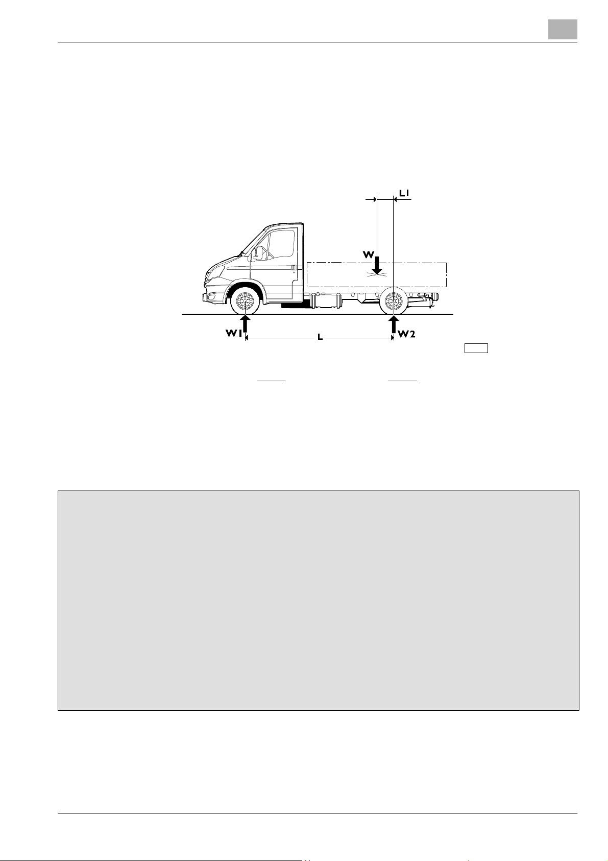
1.15.2 Determining the centre of gravity of the body and payload
Positioning on the longitudinal plane
The examples given below may be used to determine the position of the superstructure’s centre of gravity and the payload.
The technical documentation specific to each model(chassis cab drawing)give the positions permitted with thevehicle in itsstan dard
form. The masses and positioning of the single components of the vehicle are given in the chassis and weight distribution diagram.
Figure 1.2
166681
W
⋅ L
1
=
L
1
W = Body + payload (kg)
W1 = Reaction to portion of W bearing on front axle (kg)
W2 = Reaction to portion of W bearing on rear axle centre line (kg)
L1 = Distance of the centre of gravity from the rear axle centre line (mm)
L = Wheelbase (mm)
respectively L1 = L −
W
W2 ⋅ L
W
Example of calculation of the load barycentre position
Consider a 40C13 vehicle with a wheelbase of 3,450 mm with:
1. GWW = 4,200 kg (permitted maximum: 1,900 kg on the front and 3,100 kg on the rear)
2. KERB WEIGHT = 1,955 kg (1,340 kg on the fro nt axle, 615 kg on the rear)
The permitted maximum load (body + payload) will be W = 4,200 - 1,955 = 2,245 kg. Let us calculate the position of the center
of gravity in which the maximum permitted on the front axle is achieved. Let us assume an uniform distributed load .
In this case, out of 2,245 kg. W
= 1,900 - 1,340 = 560 kg will affect the front axle, while the remaining W2= 2,245 - 560 = 1,685
1
kg will affect the rear axle.
Thus, the following will be obtained:
1
= 560 kg
1. W
2. L = 3450 mm
3. W = 2245 kg
=W1x L / W = 860 mm
L
1
The center of gravity of the load (Body + payload) must not be more than 860 mm far from the rear axle; otherwise, the front
axle would be overloaded.
Dimensions and masses
Printed 603.95.241 Base- 02/2012
Page 20
1-12
GENERAL SPECIFICATIONS
D
AILY
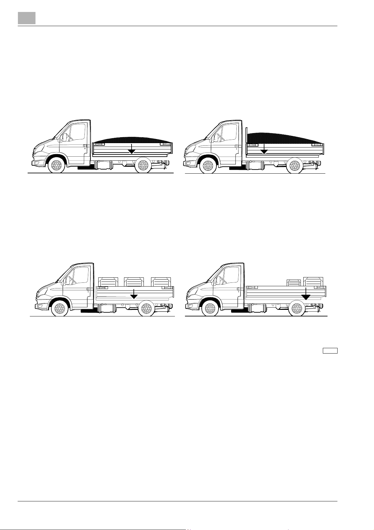
In terms of the effects of dividing the payload on the axles, consider that it is evenly distributed, with the exception of cases where
the shape of the loading bed would result in it being distributed differently.
Regarding any equipment, the actual position of the centre of gravity must be used.
When creating the superstructure or containers, loading and unloading systems for goods must be created which avoid excessive
variations on the payload distribution and/or excessive loads on the axles, with instru ctions supplied for end users if necessary.
Figure 1.3
Uniform load distribution Uneven load distribution
Figure 1.4
Uniform load distribution Uneven load distribution
(beware of axle loads and minimum axle ratio)
166682
Dimensions and masses
Base - 02/2012 Printed 603.95.241
Page 21
DAILY
GENERAL SPECIFICATIONS
1-13
Height of centre of gravity
For chassis cab and unladen vehicles, the height of the centre of gravity is given on the specific technical documentation for each
model (chassis cab diagram).
When the vehicle is complete with a superstructure and fully laden, this h eight must co mply with the maximum values permitted
by national or international regulations, particularly ECE Directive 13 on longitudinal stability and ECE Directive 111 on transverse
stability while in motion.
The following cases may arise:
a) fixed loads
b) mobile loads
c) loads that involve high aerodynamic actions
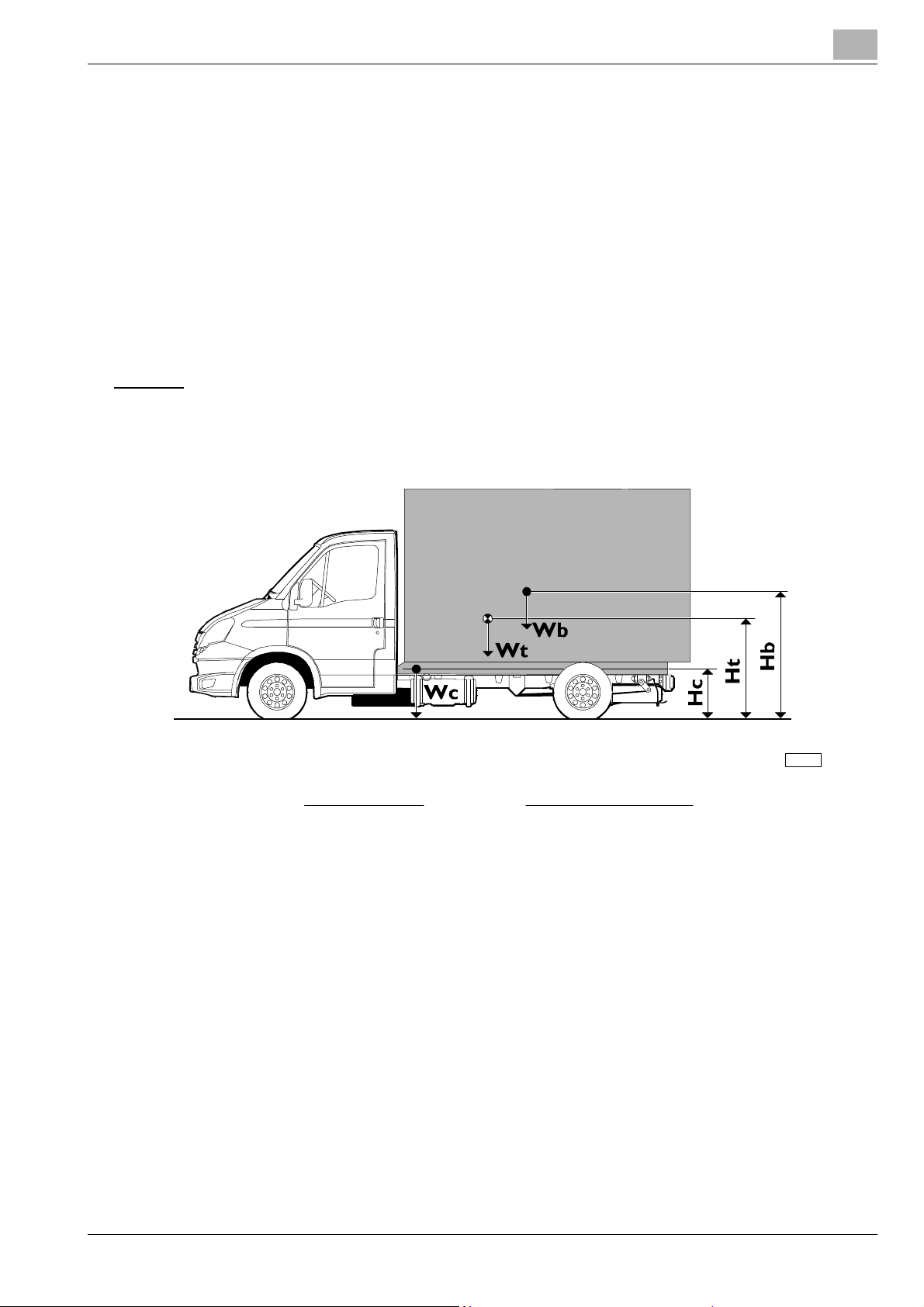
a) Fixed loads
:
Check when fully laden:
Figure 1.5
Wc . Hc + Wb . Hb
Ht =
Wc + Wb
(Wc + Wb) . Ht − Wc . Hc
Hb =
Wb
166683
Wc = Chassis cab vehicle kerb weight
Hc = Height of centre of gravity of chassis cab vehicle (laden condition)
Wb = Body and payload
Hb = Height of centre of gravity of body and payload in relation to ground
Wt = Vehicle weight when fully loaded
Ht = Height of centre of gravity of vehicle with full load
To check the vehicle with its body but no payload use the above formula but for Wb use only the vehicle unladen weight (The
position for Hc will depend on the load and deflection of the suspension).
Dimensions and masses
Printed 603.95.241 Base- 02/2012
Page 22

1-14
GENERAL SPECIFICATIONS
D
AILY
The following table shows the maximum approximate heights indicating the overall cent re of mass (payload + body and/or
equipment), with reference to the vehicle’s transverse stability.
Table 1.1
Models Centre of mass height (mm)
29L 1400
35S 1500
35C (front transverse leaf spring) 1800
35C (front longitudinal bar) - 40C 1900
45C - 50C 1950
60C - 65C - 70C 2050
b) Mobile loads
In specifications where the load may move laterally when cornering (e.g. suspended loads, liquid transport, animal transport, etc.),
dynamic transverse forces may be generated that are high enough to affect vehicle stability.
With reference to regulation ECE 111, particular attention must therefore be paid:
- to defining the height of the centre of gravity of a converted vehicle that is fully laden;
- to evaluating dynamic thrust and lateral movement of the centre of gravity;
- in considering (for liquids) the density;
- to recommending due caution in driving behaviour.
Any cases that are difficult to assess must be submitted to IVECO for approval.
c) Loads that involve hi gh aerodynamic
actions
To conversions characterised by large height and surface area (e.g.: vehicles with large advertising panels); the height of the centre
of thrust determined by high winds must be calculated very carefully.
Even with a low centre of gravity, a converted vehicle presenting a high side area may not guarantee
!
sufficient transverse stability and may be exposed to the danger of rolling over.
Particular attention must therefore be paid;
- to defining the height of the centre of gravity of a converted vehicle that is fully laden;
- to evaluating aerodynamic thrust;
- to recommending due caution in driving behaviour.
Any cases that are difficult to assess must be submitted to IVECO for approval.
Using stabiliser bars
The application of supplementary or reinforced stabiliser bars, spring reinforcements or rubber parts (with respect to point 2.11)
may allow higher values for the height of the payload CG, to be defined for each individual case.
Work must be carried out after careful evaluation of the charac teristics of the conversion, the wheelbase and the division of
transverse forces on the suspension, generally regarding both the front and the rear. Work on the front axle may be necessary with
loads concentrated behind the cab (e.g. cranes) or with highly rigid superstructures (e.g.: van bodies).
Dimensions and masses
Base - 02/2012 Printed 603.95.241
Page 23

DAILY
GENERAL SPECIFICATIONS
1-15
1.15.3 Observing the permitted weights
All limits given in IVECO documentation must be respected. It is essential that the maximum weight on the front axle is not
exceeded, under any loa d condition, so as to ensure the correct steering and braking characteristics regardless of the road surface
conditions.
Special attention must be paidto vehicles with loads concentrated on the rear protrusion (e.g. cranes, tail lift, trailers) and to vehi cles
with short wheelbase and high CG.
NOTE
Correct transverse division of loads must be ensured when positioning auxiliary units and the
superstructure. A variation of ± 4% of nominal load is permitted for each wheel (50% of the
corresponding axle load, e.g.: permitted load on axle 3000 kg, 1440 to 1560 kg load permitted for each
wheel) respecting what is permitted by the tyres, without compromising the vehicle’s braking
characteristics and stability.
Unless specifically stated otherwise for individual vehicles, the weight on the front axle must be
considered to have a minimum value of 28% of the actual weight of the vehicle (whether with
uniformly distributed loads or with loads concentrated on the rear overhang or derived from a
possible trailer).
Variations in the permissible weight
Special dispensations for maximum allowable masses may be given for special u ses; nevertheless, precise usage limitations an d
in some cases compulsory reinforcements to the vehicle have been established for these cases.
If these dispensations should exceed legal limits they must be Authorised by the Relevant Authorities.
When requesting authorisation, the following must be indicated:
- vehicle type, wheelbase, identification number, designated use;
- unladen weight on the axles (e.g. vehicles equipped with cran e) in c luding positions for the centre of gravity of the payload;
- proposals concerning the reinforcement of the vehicle components where necessary.
The reduction ofpermissiblevehicle weight(downrating) mayrequire workon some components such as thesuspension and brakes
and may require new weight calibration for the braking corrector; in these cases the necessary indications can be supplied.
Dimensions and masses
Printed 603.95.241 Base- 02/2012
Page 24

1-16
GENERAL SPECIFICATIONS
Instructionsforcorrectoperationof vehiclecomponentsandaccessibility
D
AILY
1.16 Instructions for correct operation of vehicle components and accessibility
When converting vehicles or installing any type of equipment, n o alterations must be made which would compromise correct
operation of the vehicle assemblies and components in their various work conditions.
For example:
- free access must be guaranteed to points requiring inspection, maintenance or periodic checks (e.g. replacement of battery,
accessto air suspensioncompressor)and, with closedsuperstructures,appropriate compartments andhatches must beavailable;
- the possibility to remove the various assemblies for servicing must be maintained. Work on the transmission/clu tch or
adjustments (e.g. suspension bars) must be possible without removing important elements of the added structure;
- cooling (grille, radiator, air passages, coolin g circuit etc.), fuel supply (position of pump, filters, tubing diameters etc.) and engine
air intake must not be altered;
- soundproofing panels must not be altered or removed in order not to change the approved noise emission levels. Whenever
openings are to be made (e.g. for th e passage of lon gitudinal chassis members), they must be re-closed using materials with fireand sound-proofing characteristics equivalent to the original materials;
- adequate brake and battery case ventilation must be maintained (in particular for vans);
- when positioning mudguards and wheel arches, free movement of rear wheels must be guaranteed, also when used with snow
chains;
- when the conversion is finished,the vehicle’s headlights mustbe checked in order to ensure they are correctly adjusted.Proceed
according to the indications given in the use and maintenance manual for adjustment;
- the Bodybuilder must carefully ch oose the positioning of any loose elements (e.g. spare wheel, chocks) so as to ensure they are
safely and accessibly positioned in full respect of an y national regulations.
Instructions for correct operation of vehicle components and accessibility
Base - 02/2012 Printed 603.95.241
Page 25
DAILY
Convention
GENERAL SPECIFICATIONS
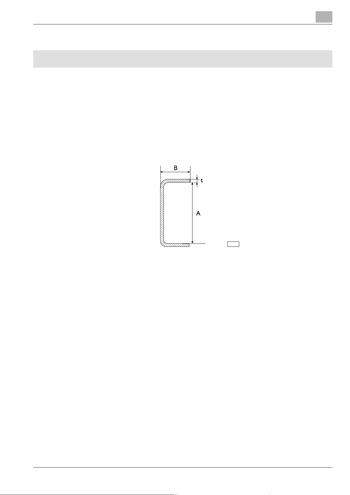
1.17 Conventions
The following conventions are used in this document:
- Wheelbase: distance between the centre line of the steering axle and that of the rear axle.
This definition differs from the definition of wheelbase indicated in EC Directives.
- Rear overhang: distance between the centre line of the rear axle and the rearmost point of the chassis side members.
- Dimensions A, B and t of the chassis section: see the figure.
Figure 1.6
1-17
91473
Convention
Printed 603.95.241 Base- 02/2012
Page 26

1-18
GENERAL SPECIFICATIONS
D
AILY
Convention
Base - 02/2012 Printed 603.95.241
Page 27

DAILY
Index
CHASSIS MODIFICATIONS
SECTION 2
Chassis modifications
2.1 General standards regarding changes to the chassis 2-5
2.1.1 Particular precautions 2-5
2.1.2 Characteristics of the material to be used when modifying the chassis 2-6
2.1.3 Stress o n the chassis 2-7
2.2 Drills on the chassis 2-8
2.2.1 Hole positioning and dimensions 2-8
2.2.2 Screws and nuts 2-9
2.2.3 Welds 2-10
2.2.4 Closing holes by welding 2-12
2-1
Page
2.3 Rust protection and paint 2-13
2.3.1 Original vehicle components 2-13
2.3.2 Added or modified parts 2-16
2.3.3 Precautio ns 2-17
2.4 Modification of the wheelbase 2-18
2.4.1 General information 2-18
2.4.2 Authorisation 2-18
2.4.3 Influence on steering 2-18
2.4.4 Influence on braking 2-19
2.4.5 Procedure 2-19
2.4.6 Checking chassis stress 2-20
2.4.7 Cross members 2-20
2.4.8 Chassis reinforcements 2-21
2.4.9 Changes to the transmissions 2-21
2.5 Change of the rear overhang 2-22
2.5.1 General information 2-22
2.5.2 Authorisation 2-22
2.5.3 Shortening 2-22
Index
Printed 603.95.241 Base — 02/2012
Page 28

2-2
CHASSIS MODIFICATIONS
D
Page
2.5.4 Elongat ion 2-22
2.6 Application of the towing hook 2-24
2.6.1 Adjusting the vehicle for t owing 2-24
2.6.2 Precautions for installation 2-24
2.6.3 Hook types 2-24
2.6.4 Towing hook for central axle trailers 2-25
2.6.5 Rear cross member in a lowered position 2-27
2.7 Application of a supplementary axle 2-29
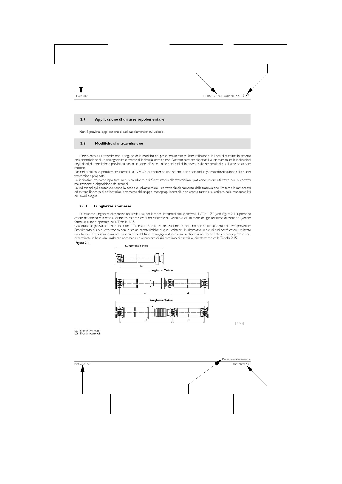
2.8 Changes to the transmission 2-29
2.8.1 Permitted lengths 2-29
2.8.2 Sect i on positioning 2-32
2.9 Changes to the air intake and engine exhaust systems 2-34
AILY
2.9.1 Intake 2-34
2.9.2 Engine exhaust 2-34
2.10 Changes to the engine cooling system 2-35
2.11 Operations on the suspensions 2-36
2.12 Changes to the heating/cooling sy stem 2-38
2.12.1 Installation of a supplementary heating system 2-38
2.12.2 Installation of an air conditioning system 2-40
2.13 Operations on sheet metal 2-41
2.13.1 General information 2-41
2.13.2 Operations on the cab 2-42
2.13.3 Operations on the body (vans and c ombi) 2-44
2.13.4 Creating deep cabs 2-51
2.13.5 Occupant protection 2-52
2.14 Changing tyre size 2-53
2.15 Work on the brake system 2-55
2.15.1 Piping 2-55
2.15.2 Braking corrector 2-59
2.15.3 ESP (Electronic Stability Program) 2-61
Index
Base — 02/2012 Printed 603.95.241
Page 29

DAILY
CHASSIS MODIFICATIONS
2.15.4 ESP system down grading 2-62
2.16 Electrical system: work and current draws 2-64
2.17 Moving components and fastening supplementary units and equipment 2-65
2.18 Road transport of hazardous goods (ADR) 2-68
2.19 Application of a retarder 2-69
2.20 Changes to the under-run protection bar 2-70
2.21 Rear under-run protection and wheelhouses 2-70
2.22 Mudflaps 2-71
2.23 Side protections 2-71
2.24 Chocks 2-71
2-3
Page
Index
Printed 603.95.241 Base — 02/2012
Page 30

2-4
CHASSIS MODIFICATIONS
D
AILY
Index
Base — 02/2012 Printed 603.95.241
Page 31

DAILY
2222.2
Gener al standards re garding change s tothe chas sis
CHASSIS MODIFICATIONS
2-5
2.1 General standards regarding changes to the chassis
Keep the following in mind:
- welding is absolutely prohibited on the load bearing structures of the chassis (with the exception of what is specified in
paragraphs 2.2.3, 2.4, and 2.5);
- drilling is not permitted on the side member wings (with the exception of what is specified in paragraphs 2.2.3, 3.1.1 and 3.14.3);
- if it is permitted to make changes to the con nections implemented with rivets, they may be replaced with flanged head screws
and nuts or with c lass 8.8 hexagonal head screws with the next highest diameter and nuts with loosening prevention systems.
Screws larger than M12 must not be used (maximum hole diameter 13 mm), unless otherwise specified;
- if connections are restored that use screws, it is mandatory to check the suitability of the screws before reusing them and to
tighten them to a suitable torque;
If safety components are reassembled, it is prohibited to reuse already used screws and it is mandatory
to tighten to the specifically specified torque (contact the Service Network for information about the
!
value).
- ifsafety componentsare reassembledand when rivets arereplacedwith screws,the closure ofthe connection mustbe rechecked
after driving approx. 500 - 1000 km.
2.1.1 Particular precautions
During welding, drilling, grinding and cutting operations near brake pipes or electric cables, take
suitable precautions to protect them, disassembling them if necessary (follow the instructions
!
provided in chapters 2.15 and 5.4).
Figure 2.1
91444
General standards regarding changes to the chassis
Printed 603.95.241 Base — 02/2012
Page 32

2-6
CHASSIS MODIFICATIONS
D
AILY
Precautions for the alternator and the electric/electronic components
In order to prevent damage to the rectifier with diodes, the batteries must never be disconnected (and the disconnecting switch
must not be opened) while the engine is running.
If the vehicle must be started by means of towing (which is strongly advised against), make sure that the battery is charged an d
connected in order to provide the ECU engine control unit with the minimum operating voltage.
If the battery must be charged, it must be disconnected fromthe vehicle circuit. If the engine must be startedusing external charging
devices, do not use the ”start” function (if the equipment has this function) in order to prevent peaks of current that could damage
the electric and electronic components.
The start-up must o nly be carried out using an external battery carriage, being careful to respect the polarity.
Ground connections
In general, the vehicle’s original ground connections must not be changed. If it is necessary to move these connections or create
additional ground points, use the holes already existing in the c hassis if possible, being careful to:
- remove mechanically, through filing and/or with a suitable chemical product, the paint from both the c h assis and terminal sides,
creating a contact surface that is smooth and even;
- apply suitable paint with high electric conductivity between the terminal and the metalsurface (e.g. zinc basedpaint Part number
IVECO 459622 from the company PPG);
- connect the ground within 5 minutes of applying the paint.
For signal level ground connections (e.g.: low absorption sensors or devices), do not use the standardised IVECO points ”m1” (on
the engine block, near the starter motor) or ”m2” and make the ground connections of the signal cables on points separate from
the power cables and cables used as radiofrequency shields.
For electronic equipment, avoid making ground connections between devices in a linked manner, foreseeing individually wired
ground connections, optimising the length (prefer a shorter path).
Braking and electrical system
For more information about the braking and electrical systems, see chapters 2.15 and 5.4.
2.1.2 Characteristics of the material to be used when modifying the chassis
When making changes to the vehicle chassis (all models and all wheelbases) and when applying reinforcements directly on the
side members, the material to be used must comply with what was used originally for the chassis with regard to quality (Table 2.1)
and thickness (Table 2.2).
If it is not possible to find material that has the indicated thickness, material may be used with the next highest standard thickness.
Table 2.1 - Material to be used when making changes to the Standard IVECO chassis 15-2110 and 15-2812
Steel name
IVECO FEE420
Europe S420MC
Germany S420MC
UK S420MC
Ultimate tensile
strength
(N/mm
2
)
530 420 23
Yield strength
(N/mm
2
)
Elongation
(%)
N.B. For 70C vehicles only, the material must be FEE490 with:
- Ultimate tensile strength 610 N/mm
- Yield strength 490 N/mm
- Elongation 19%
General standards regarding changes to the chassis
Base — 02/2012 Printed 603.95.241
2
2
Page 33

DAILY
CHASSIS MODIFICATIONS
Table 2.2 - Section dimension and thickness of the chassis
2-7
Class Type Wheelbase [mm]
truck
29L - 35S
35C
van
lightened
campe r
3950 (camper) 1825
3000 short overhang 840
3000 long overhang 1240
3000 (1) 1240
35C-50C truck
4100 (1) 1715
4750 (2) 2350
3000 short overhang 840
35C - 40C van
3000 long overhang 1240
3000 short overhang 840
45C - 50C van
60C - 65C -
truck
3000 long overhang 1240
70C
van 3950 1825
(1) = only 35C - 40C
(2) = only 45C - 50C
Chassis rear
overhang
[mm]
3000 920
3450 1355
3750 1665
3300 1460
3950 1825
3750 1665
3950 1825
3450 1355
3750 1665
4350 1885
3300 1460
3950 1825
3300 1460
3950 1825
3450 1355
3750 1665
4350 1890
4750 2350
AxBxt
section wheelbase
area side member
[mm]
AxBxt
section rear
overhang area side
member [mm]
144 X 56 X 3 94 X 56 X 3
144 X 56 X 3 94 X 56 X 3
174 X 70 X 4 114 X 70 X 4
174 X 69 X 3 114 X 69 X 3
174 X 70 X 4 114 X 70 X 4
174 X 69 X 5 174 X 69 X 5
2.1.3 Stress on the chassis
In no case it is allowed to exceed the following stress values under static conditions:
Table 2.3
Range Static stress permitted on the chassis σ amm (N/mm2)
Road use Off-road use
Daily 120 80
In any case, comply with the most restrictive limits defined by national regulations.
Welding operations cause a deterioration of the material characteristics, therefore, when checking the stress in the thermally altered
area, consider a reduction of approx. 15% of the resistance characteristics.
General standards regarding changes to the chassis
Printed 603.95.241 Base — 02/2012
Page 34

2-8
CHASSIS MODIFICATIONS
Drillsonthechassis
D
AILY
2.2 Drills on the chassis
When it is necessary to fit auxiliary parts or assemblies to the c hassis, th e existing holes made in the factory should be used if
possible.
Drilling the flanges of the vehicle side members is strictly prohibited, with the exception of what is
indicated in paragraph 3.3.1.
!
In special cases (application ofbrackets, angle irons, etc.) where new holes haveto be drilled, these holes shallbe made on the vertical
rib of the side member and shall be accurately burred and bored.
2.2.1 Hole positioning and dimensions
The new holes shall not be drilled in the areas subjected to greater stress (e.g. spring supports) and areas where the side member
section changes.
The diameter of the holesshould be suitable forthe thickness of the panel andmust not exceed 13 mm (unless otherwise specified).
The distance of the hole axis from the edges of the side member must n ot be less than 30 mm, and the axes of the holes must not
be between them, or less than 30 mm with respect to the existing ones.
Theholesmustbeoffset,asshownintheFigure2.2.
The original drilling diagrams must be followed when moving spring supports or cross members.
Figure 2.2
102420
Drills on the chassis
Base — 02/2012 Printed 603.95.241
Page 35

DAILY
CHASSIS MODIFICATIONS
2-9
2.2.2 Screws and nuts
In general, it is recommended to make connections of the the same type and class as those foreseen for similar fastenings on
the original vehicle (Table 2.4).
Screws of class 8.8 and 10.9 must be hardened and tempered and, for applications with diameter
use stainless steel parts.
The foreseen coatings are Geomet and galvanisation. If the screws are subjected to welding, the Geomet coating is not
recommended.
If space permits, use screws and nuts wit h a flanged head.
Use nuts with loosening prevention systems and remember that the tightening torque must be applied to the nut.
Table 2.4 - Screw resistance classes
≤ 6 mm, it is recommended to
Resistance class Use
Ultimate tensile strength
(N/mm
2
)
4.8 Non-load bearing screws 400 320
5.8 Low resistance screws 500 400
Medium resistance screws
8.8
(cross members, cut
800 640
resistance plates, brackets)
High resistance screws (spring
10.9
mounts, stabilizer bars and
1000 900
shock absorbers)
Yield strength (N/mm2)
Drills on the chassis
Printed 603.95.241 Base — 02/2012
Page 36

2-10
CHASSIS MODIFICATIONS
2.2.3 Welds
The welds must only be made by qualified personnel with suitable equipment, and always to
professional standards (see standard EN 287). Any operation performed that does not comply with the
!
instructions provided by IVECO could seriously damage the on-board systems, jeopardise vehicle
safety and cause damage not covered by the warranty.
Welds are permitted:
- in side member joints, when lengthening and shortening;
- when applying angular reinforcements in the area involved with th e side member modification, as specified below
(see Figure 2.3).
Figure 2.3
D
AILY
91448
In the event of electrical arc welding, observe the following instructions to protect the electric components and electronic control
units:
- before disconnecting the power cables ensure there are no active electric users;
- if an electric circuit breaker (main switch) is present, wait for it to complete the cycle;
- disconnect the battery negative pole;
- disconnect the positive battery pole without grounding it, and DO NOT short circuit it with the negative pole;
- disconnect the c onnectors from electronic control units and proceed carefully, avoiding touching the pins of control unit
connectors;
- if welds are to be made near an electronic control unit, disconnect the control unit from the vehicle;
- connect the welding machine ground directly to the piece to be welded;
- protect the plastic pipes from heat sources, removing them if necessary;
- when welding near leaf springs or air springs, protect their surfaces appropriately from welding sprays;
- avoid touching the spring leafs with the electrodes or pliers.
Drills on the chassis
Base — 02/2012 Printed 603.95.241
Page 37

DAILY
CHASSIS MODIFICATIONS
2-11
Welding procedures
a) Carefully remove any paint and traces of oxidation from the parts of the chassis involved with the welding as well as those that
must be covered with reinforcements.
b) Cut the side members with a slanted or vertical cut. The side membersmust not be cut at the points wherethe chassiscontour
and width changes or where stress is greater (e.g. spring mounts). The separation line must not involve the holes on the side
member (see Figure 2.4).
Figure 2.4
YES
NO
YES
NO
YES
YES
YES
YES
91446
c) Make a 60° V shaped chamfer on the parts to join on the inner side of the side member along the entire length of the area
to be welded (see Figure 2.5).
Figure 2.5
91447
d) Perform arc welding with several passes using carefully dried basic electrodes.
Avoid current overload; the weld must be free from marginal cuts and waste material.
e) Repeat in the other direction and make the weld as specified in point d).
f) Allow the side members to cool slowly and uniformly. They must not be cooled using an air jet, water or another method.
g) Grind off the excess material.
h) Apply angular steel reinforcements on the inside, with the same specifications as the steel used in the chassis. The approximate
minimum dimensions are specified in Figure 2.3.
The reinforcements may only be secured on the vertical rib of the side member and may be implemented with welding beads,
false spots, screws or rivets (also Huck rivets).
The welding bead section and length, as well as the number and arrangement of false spots, screws or rivets, must be suitable
to transmit the bending and cutting moments of the section.
i) When the work is completed, protect with rust proofing (see paragraph 2.3.2).
Drills on the chassis
Printed 603.95.241 Base — 02/2012
Page 38

2-12
CHASSIS MODIFICATIONS
2.2.4 Closing holes by welding
When making new holes, and if they are too close to already existing holes (see Figure 2.2), the latter can be closed by welding
them.
To ensure that this operation will be suc cessful:
- smooth the external edge of the hole;
- apply a strip of copper inside the side member to retain the weld material;
- perform the welding on both sides of the side member and remove the residues.
In order to close holes with a diameter greater than 20 mm, rounded washers can also be used, welding on both sides.
D
AILY
Drills on the chassis
Base — 02/2012 Printed 603.95.241
Page 39

DAILY
Rust protecti on and paint
2.3 Rust protection and paint
CHASSIS MODIFICATIONS
2-13
NOTE
All components assembled on the chassis must be painted according to IVECO Standard 18-1600
colour IC444 RAL 7021 70/80 gloss.
2.3.1 Original vehicle components
Table 2.5 shows the protection and painting classes required for the original vehicle components; Table 2.6 sh ows the classes
for non painted or aluminium parts and Table 2.7 shows the parts for the painted classes.
Table 2.5 - Class of protection - IVECO Standard 18 - 1600 (Table I)
Class Part requirements Examples of involved parts
Body - Rear-view mirrors - Windscreen wipers - Sun visor
A Parts in direct contac t with atmospheric agents.
B
B2
Parts in direct contact with atmospheric agents with
mainly structural characteristics, in direct view.
B1 Only for rear and front axles
C
Parts in direct contact with atmospheric agents, not in
direct view.
D Parts not in direct contact with atmospheric agents.
metal structure - Metal bumper - Cab hook-up lock Door stop device - Body fixing elements (screws, bolts,
nuts, washers), etc.
Chassis and relative parts, including fastening elements.
Parts under the grille (class B).
Running boards outside the cab.
Engine and relative parts
Pedal assemblies - Seat frames - Fastening elements - etc.,
installed inside the cab.
NOTE
The parts must be supplied only with cataphoresis or a rust inhibitor (Table III). The enamel will be
applied during the chassis finishing phase.
Rust protection and paint
Printed 603.95.241 Base — 02/2012
Page 40

2-14
CHASSIS MODIFICATIONS
Table 2.6 - Various unpainted, aluminium parts and components - IVECO Standard 18 - 1600 (Table IV)
D
AILY
Type of protection
IVECO
standard
A B-B1-B2 C D
Classes
Stainless steel ¡ 18-0506 yes - - -
GEO 321-8
GEO 500-8
GEO 321-8 PM
GEO 321-8 PML
yes -
GEO 321-8 PL
Geomet
(HHH)
GEO 500-8 PL
GEO 321-5
18-1101
- -
GEO 500-5
GEO 321-5 PM
GEO 321-5 PML
GEO 321-5 PL
-
yes
yes
Class B1
GEO 500-5 PL
wheel studs
FE/ZN 12 II
- - yes yes
- - yes yes
Galvanisation
(HH)
FE/ZN 7 IV
FE/ZN 12 IV
FE/ZN 7 IV LUB
18-1102
FE/ZN 7 IV S
- yes yes yes
yes yes yes
yes
Aluminium
FE/ZN 12 IV S
Anodic
oxidation
Painting
18-1148 yes
See
Table III
¡ Coupling with other metal materials must not cause a ”pile effect”.
(
HH) Coatings free of hexavalent chromium.
HHH) Coatings free of chromium salts.
(
Rust protection and paint
Base — 02/2012 Printed 603.95.241
Page 41

DAILY
CHASSIS MODIFICATIONS
Table 2.7 - Painted parts - IVECO Standard 18 - 1600 (Table III)
2-15
Cycle phase description
MECHANICAL SURFACE
CLEANING¡
PRETREATMENT
CATAPHORESIS
RUST PROOFING
STONE RESISTANT BOTTOM
ENAMEL
Classes
A B § B1¤ B2 C D
Sandblasting/shotblasting -
yes L - yes L yes L yes LBrushing
Sanding
yes L
Iron phosphating (only for
ferrous materials that are not
previously coated)
yes L - yes L yes L yes L
Zinc phosphating l yes
High thickness (30-40 μm) yes ©
Medium thickness (20-30 μm) yes ¢
yes L
¥
yes L
Finishing acrylic (>35 μm) - Bi-component (30-40 μm)
Single-component (30-40 μm) - yes Single (130 °C)
or bi-component (30-40 μm)
Single (130 °C)
or bi-component (30-40 μm)
-
yes ¢ - - - - -
yes
yes - yes
yes L -
Powders (40-110 μm) yes £
Single-component at low
temperature (30-40 μm)
- - yes
yes L
¥
¨¥
yes L
¨
- yes L
yes L
¥
yes L
yes L
¦
¡ = Operation to be performed if there are shearing burrs, oxidation, welding scraps, laser cut surfaces.
© = Two-layer body cycle.
¢ = Three-layer body cycle.
£ = As an alternative to single or bi-component enamel only for body parts (windscreen wipers, rear-view mirrors, etc.).
¤ = Rear and front axles only.
¥ = Exclusions of parts that cannot be immersed in pretreatment or paint baths as their functionality could be jeopardised (e.g.: mechanical parts).
¦ = Only if the colour is defined on the drawing according to I.C.
§ = For fuel tanks in ferrous or precoated plate.
¨ = Only parts to be installed on the engine.
l = For galvanised plate or aluminium, specific phosphates must be used.
L = Alternative products and cycles for the same phase, providing they are compatible with the parts to be treated.
Rust protection and paint
Printed 603.95.241 Base — 02/2012
Page 42

2-16
CHASSIS MODIFICATIONS
D
AILY
2.3.2 Added or modified parts
All the vehicle parts (body, chassis, equipment, etc.) that are added or that are changed must be protected against oxidation
and corrosion.
Areas without protection are not accepted on ferrous materials.
Tables 2.8 and 2.9 indicate the minimum treatments to which the modified or added components must be subjected when it is not
possibleto protect them using the same protection used for the original components. Different treatments are permitted providing
that the same oxidation and c orrosion protection is guaranteed.
Do not use powder enamels directly after degreasing.
Parts in light alloy, brass and copper are not protected.
Table 2.8 - Added or modified painted parts
Cycle phase description
Mechanical surface cleaning (including the removal of
burrs/oxidation and cleaning cut parts)
A-B-D(1)
Brushing/sanding/sandblasting
Pretreatment Degreasing
Rust proofing Bi-component (30-40 μm) (2)
Enamel Bi-component (30-40 μm) (3)
Class
(1) = Changes on rear axles, front axles and engine (classes B1 and C) not permitted
(2) = Preferably epoxy
(3) = Preferably polyurethane.
Table 2.9 - Added or modified unpainted or aluminium parts
Class
Type of protection
A-B(1) D
Stainless steel
Geomet -
yes
Galvanising (1) - yes
(1) = Free of hexavalent chromium.
-
Rust protection and paint
Base — 02/2012 Printed 603.95.241
Page 43

DAILY
CHASSIS MODIFICATIONS
2.3.3 Precautions
a) On the vehicle
Suitable precautions must be taken to protect the parts for which paint may be harmful for con servation and operation:
- rubber o r plastic flexible pipes for pneumatic and hydraulic systems;
- gaskets, parts in rubber or plastic;
- propeller shaft and power take-off flanges;
-radiators;
- shock absorber, hydraulic or pneumatic cylinder stems;
- air bleeder valves (mechanical units , air tanks, thermostarter preheating tan ks, etc.);
- fuel sediment filter;
-plates,acronyms.
If painting is necessary after disassembling the wheels, proceed as follows:
- protect the wheel rim contact surfaces on the hubs and the stud/fixing nut contact areas;
2-17
- ensure suitable protection for the brake discs.
Electronic components and modules must be removed.
b) Engines and their electrical and electronic components
Suitable precautions must be taken to protect:
- engine and vehicle wiring, including ground contacts;
- sensor/actuator side and wiring side connectors;
- sensors/actuators on the flywheel, on the flywheel rev sensor support bracket;
- the plastic and metal pipes in the entire diesel circuit;
- the complete diesel filter base;
- the electronic control unit and its base;
- the entire inner part of the soundproofing cover (injectors, rail, pipes);
- the common rail pump with regulator;
- the vehicle’s electrical pump;
- the tank;
- the front belt coil and relative pulleys;
- the power steering pump and relative pipes.
When the painting operation is complete and before drying in the oven (max. temperature 80 °C), all
the parts that may be harmed by exposure to heat must be removed or protected.
!
Rust protection and paint
Printed 603.95.241 Base — 02/2012
Page 44

2-18
CHASSIS MODIFICATIONS
Modificati onof the whe elbase
D
AILY
2.4 Modification of the wheelbase
2.4.1 General information
Any change to the wheelbase that involves the electrical circuits and/or the relocation of the
electrical/electronic components requires approval and must be performed in compliance with the
!
instructions in chapter 5.4.
In general, the wheelbase must be changed by working on a standard production wheelbase that is as close as possible to the
onetobecreated.
If permitted by the dimension of the superstructure, it is preferable to create wheelbases that are equal to those foreseen by normal
production, as this makes it possible to use original propeller shafts and predefined cross member positions.
Please note that if y ou want to create a size that is smaller than the approved minimum or greater than the approved maximum,
authorisation must be requested from IVECO.
For vehicles equipped with an ESP system, see paragraph 2.15.3.
!
2.4.2 Authorisation
The wheelbase may be changed without specific IVECO approval only when:
- implementing one of the lengths foreseen in the catalogue for the type of vehicle to be transformed;
- replicating the structure (side member section; number, type and positions of the cross members), the circuits and systems on
the standard chassis corresponding to this length.
If both these conditions do not exist simultaneously , with which th e diagram of the transformed chassis is identical to the diagram
of an original chassis, the c hange must be submitted for approval.
The workshop that makes the transformation must provide sufficient guarantees from a technological and control point of view
(qualified personnel, suitable operating processes, etc.).
The work must be carried out in compliance with th ese directives, in accordance with suitable regulations and adaptations, as well
as proper precautions (e.g. check the need to reset the control unit parameters, positioning of the exhaust pipe, compliance with
the minimum tare on the rear axle, etc.) foreseen for corresponding original wheelbases.
2.4.3 Influence on steering
In general, lengthening the wheelbase has a negative influence on steering characteristics.
When required by regulations, do not exceed the limits required for the swing-out radius, the forces on the steering wheel and the
relative inscribability times (e.g. ECE Regulation or EC Directive in force).
Table 2.10 specifies the maximum wheelbase lengthening values possible with standard steering, the maximum load permitted on
the front axle and the required tyres for the vehicle.
If longer wheelbases are necessary, specific approval must be requested and measures must be adopted to improve steering, such
as the reduction of the maximum load on the front axle or the creation of an offset with lower values.
Also the use of a supplementary pump must be authorised, whereas for the subsequent installation, a specialised company must
be used.
Modification of the wheelbase
Base — 02/2012 Printed 603.95.241
Page 45

DAILY
CHASSIS MODIFICATIONS
Table 2.10 - Maximum permitted wheelbase elongation
2-19
Model Front suspension
Maximum wheelbase
(mm)
29L, 35S Transverse 4100
35C, 40C, 45C, 50C Transverse (maximum permitted 1800 kg) 4100
35C, 40C, 45C, 50C Torsion bar (maximum permitted 1900 kg) 4750
60C, 65C, 70C Torsion bar 4750
2.4.4 Influence on braking
In general, shortening the wheelbase has a negative influence on braking characteristics.
Table 2.11shows the limits for wheelbase modification.Checkwith the IVECO - Homologation & Technical Applicationdepartment
about the conditions (brake cylinders, minimum tares, technically permissible weights, tyres, height of the centre of gravity) with
which these values are permitted.
Table 2.11 - Braking, limits for wheelbase modification
Model Version
Minimum (mm) Maximum (mm)
29L, 35S Truck, van 3000 3950
35C, 40C Truck, van 3000 4100
45C, 50C Van 3000 4750
45C, 50C Truck 3450 4750
60C, 65C, 70C Truck, van 3300 4750
Wheelbase
In the case of vehicles equipped with an ASR system, the setting data must be updated.
!
2.4.5 Procedure
To obtain a good result, proceed as follows:
- position the vehicle so that the chassis is perfectly flat, using suitable stands;
- disconnect the propeller shafts, the brake system pipes, wiring and anything else that could prevent the work from being
performed correctly;
- identify the reference points on the chassis (e.g. pilot holes, suspension mounts);
- markthe reference pointswitha light punching line on the upper wings of both side members, after checking that the connecting
one is perfectly perpendicular to the vehicle’s longitudinal axis;
- if moving the suspension mounts, identify the new position using the previously determined references;
- check that the new dimensions are identical on the left and right sides; the diagonal check, for minimum lengths of 1500 mm,
must not detect deviations greater than 2 mm;
- make the new drill holes using the mounts and cross member plates as a mask if other equipment is not available;
- fasten the mounts and the cross members using rivets or screws; if screws are used, ream the holes and use calibrated screws,
class 10.9, with nuts with loosening prevention systems; if their dimensions permit it, flanged head screws and nuts can be used;
- if cutting the chassis (to be carried out according to the instructions on page 2-11, point b) determine a second line of reference
points so that the area to be worked on is contained between these and the previous ones (ensure a minimum distance of 1500
mm after the operation is complete). Move the points relative to the cutting area inside the two lines of reference, proceeding
according to the in structions in paragraph 2.2.3;
Modification of the wheelbase
Printed 603.95.241 Base — 02/2012
Page 46

2-20
CHASSIS MODIFICATIONS
D
AILY
- beforeweldingcheck that the side members,including anypart that wasadded,are perfectly alignedand thenperform thecontrol
measurement on the two sides and diagonally, as previously indicated.
Apply the reinforcements according to t he instructions in paragraph 2.2.3.
Additional information
- Protect the surfaces from oxidation as specified in paragraph 2.3.2.
- Restore the braking and electrical systems according to what is specified in chapters 2.15 and 5.4.
- For operations on the transmission, follow the instructions in chapter 2.8.
2.4.6 Checking chassis stress
When lengthening the wheelbase, in addition to providing local reinforcement in corresponding of the side member joint, the
fitter must also foresee reinforcements in order to create, for the entire wheelbase length, resistance modules of a section no less
than what is foreseen by IVECO for the same wheelbase or the next highest one. Alternatively, if permitted by local regulations,
larger sized sections of th e sub-frame may be adopted.
The fitter must check that the stress limits required by national regulations are observed. The stress may not exceed the stress on
the chassis in the original wheelbase, in the case of a uniformly distributed load and with the chassis considered as a beam placed
in correspondence of the suspension mounts.
If elongation is done starting from a longer original wheelbase, the reinforc ements must be provided in fu n ction of not only the
amount of elongation but also of the type of bodywork that is created and the vehicle use.
2.4.7 Cross members
The need to use one or more cross members depends on:
- the amount of the elongation;
- the position of the transmission support;
- the welding area;
- the point of application of the forces coming from the superstructures;
- conditions of vehicle use.
If there is a supplementary cross member, it must have the same characteristics of the ones already on the chassis (resistance to
bending and torsion, material quality, connections to side members, etc.).
Figure 2.6 shows an implementation example.
An additional cross member must be provided for extensions greater than 600 mm.
In general, the distance between the two cross members must not exceed 1000 ÷1200 mm.
The minimum distance between two cross members, particularly for ”heavy duty use” must not be less than 600 mm; this limitation
excludes the ”light” cross member for transmission and shock absorber support.
Figure 2.6
102421
Modification of the wheelbase
Base — 02/2012 Printed 603.95.241
Page 47

DAILY
CHASSIS MODIFICATIONS
2-21
2.4.8 Chassis reinforcements
Figure 2.7 shows some examples of solutions that can be implemented.
The reinforcements must be continuous and must involve the entire length of the vehicle chassis to the cab. For their connection
tothesidemember,inthecaseofanangularsection,rivetsorscrews with a resistance class of 8.8 must be used; the diameter and
distribution must make it possible for the section to provide the foreseen contribution to resistance.
In the rear overhang area, and for about half of the wheelbase (in any case no less than 2 m from the front axle) it is recommend e d
to make a shear-resistant connection.
Bending stresses must be foreseen on the transformed chassis that are no greater than those on the chassis of the original vehicle,
in the corresponding sections.
Figure 2.7
102422
1. Bracket - 2. Plate - 3. Screws or rivets
To prevent consequences on the resistance of the original sections, it is not permitted to apply reinforcement plates directly on
the wings of the side members using holes filled with welding.
Alternatives may be authorised by IVECO only when demonstrated requirements exist, connected to the subsequent phase of
installing the superstructure.
In these c ases, due to the deteriorationcaused by welding, it is a good idea to consider a reduction in material characteristics of
approx. 15%.
When sizing the reinforcements use the material suggested in Table 2.1 and the static stress values on the chassis specified in
Table 2.3 may not be exceeded.
In any case, comply with the most restrictive limits defined by national regulations.
2.4.9 Changes to the transmissions
To check the permitted changes, refer to chapter 2.8.
Modification of the wheelbase
Printed 603.95.241 Base — 02/2012
Page 48

2-22
CHASSIS MODIFICATIONS
Change of the rear overh ang
D
AILY
2.5 Change of the rear overhang
2.5.1 General information
When changing the rear overhang, keep in mind the impact this has on the effects of the distribution of useful load on the axles,
with respect to the loads specified by IVECO (see chapter 1.15). It is necessary to comply with the limits specified by national
regulations as well as the maximum distances from the rear structure edge and the heights off the ground, defined for the towing
hook and the under-run protection. The distance from the chassis end to the rear edge of the superstructure must not normally
exceed 350 ÷ 400 mm.
If it is necessary to move the rear cross member fixed with screws, it is necessary to maintain the same type of standard connection
(number of screws, dimensions, resistance class).
If a towing hook is to be applied, sufficient distance (approx. 350 mm) must be left between the rear cross member and the nearest
one for possible hook assembly and disassembly operations.
If the work is done up to professional standards and in accordance wit h the instructions provided here, theo riginally defined towable
weight can remain unvaried.
The party who c arries out the work is responsible for it.
2.5.2 Authorisation
The rear elongations of the chassis as well as shortening to a value shorter than what is foreseen standard for each model, if
implemented according to the instructions provided here, do not need to be specifically authorised.
For vehicles intended for special use, where load distribution is predefined and fixed, the rear overhang can be lengthened with values
greater than60% of the wheelbase, providing that they comply with the conditionsset forth in Paragraph 1.15.3,Directive EEC97/27
and the relative national implementations with regard to the swing-out radius.
2.5.3 Shortening
When shortening the rear overhang of the chassis, the last cross member must be moved forward.
When the rear cross member results as being located too near to an existing one, the latter can be removed if it is not involved
with the suspension mounts.
For vehicles equipped with an ESP system, see paragraph 2.15.3.
!
2.5.4 Elongation
The possible solutions, based on the amount of elongation, are shown in Figures 2.8, 2.9 and 2.10.
Also a straight cut is permitted for the chassis. The minimum dimensions of the reinforcements to be applied to the area involved
with the change, are specified in Figure 2.3.
Figures 2.8 and 2.9 show the solution foreseen for elongations that do not exceed 300 ÷ 350 mm; in this case the reinforcement
angle bars, which also provide a connection between the cross member and the chassis, must h ave the same thickness and width
of the original connection plate. The connect ion between the cross member and plates, which was originally implemented using
rivets, can be done using 8.8 class screws with the next highest diameter, and nuts with loosening prevention systems.
For vehicles equipped with an ESP system, see paragraph 2.15.3.
!
Change of the rear overhang
Base — 02/2012 Printed 603.95.241
Page 49

DAILY
The solution foreseen for elongations greater than 350 mm is shown in Figure 2.10.
Figure 2.8
Figure 2.9
CHASSIS MODIFICATIONS
2-23
Figure 2.10
102427
If the amount of the elongation is con siderable, it is necessary to assess on a case by case basis if a supplementary cross member
is needed in order to ensure suitable torsional rigidity for the chassis. A supplementary cross member, with the standard
characteristics, must be inserted when the distance between the two cross members is greater than 1200 mm.
Change of the rear overhang
Printed 603.95.241 Base — 02/2012
Page 50

2-24
CHASSIS MODIFICATIONS
Applicati onof the towi nghook
D
AILY
2.6 Application of the towing hook
2.6.1 Adjusting the vehicle for towing
The transformation from a non-towing version to an approved towing version is permitted without the specific need for
authorisation by IVECO.
A vehicle that is not originally setup for towing can be adjustedfor this purpose by adding a specific ”towing section”, which means
inserting the assembly of components that are indicated in the t ype-approval documentation of the t o wing version (chassis cross
member, electrical coupling joint, towing hook, chronotachograph, etc...).
Pleasenote that the assembly of the chronotachograph, basedon current regulations, may only be performed by the IVECO service
Network.
2.6.2 Precautions for installation
The towing hook must be suitable for the permitted loads and must be type-approved by national standards.
Since it is an important element with regard to safety, the towing hook must not be modified.
!
When fastening the hook to the cross member, it is necessary to comply with the requirements of the hook manufacturer as well
as the limitations determined by current regulation s (minimum spaces for the electrical system joint and brake joint, maximum
distance between the hook pin axle and rear edge of the superstructure, etc.).
If the hook attachment flange does not have drill holes suitable for the existing ones on the rear vehicle cross member, changing
the drill holes on the latter may be authorised after applying suitable reinforcements.
The fitter is obliged to create and install the superstructure in a manner that makes it possible to perform the necessary manoeuvres
and check the hook without obstacles or danger.
Freedom of movement must be guaranteed for the trailer drawbar.
2.6.3 Hook types
The types of available hooks are:
a) ball
b) pin (automatic)
Pin hooks may only be installed on the truck version and if a suitable cross member is used.
If not supplied directly by IVECO, both types must be type-approved in compliance with current standards.
Table 2.12 contains data for the towing hooks available on the production line.
Table 2.12 - Type-approved hooks
Type Class D(kN) DC(kN) V(kN) EC type-approval no.
GS500 A50-X 22.5 - 25.0 AND 11*94/20*0533*00
GA381 S 22.5 - 25.0 AND 11*94/20*1613*01
Application of the towing hook
Base — 02/2012 Printed 603.95.241
Page 51

DAILY
Applicati onof the towi nghook
CHASSIS MODIFICATIONS
2-25
2.6.4 Towing hook for central axle trailers
A trailer is defined as a central axle type when it has on e or more axles close to each other.
Particularly due to the effect of the vertical dynamic loads, with this type of trailer, the rear vehicle cross member is subjected to
significant stress.
For the same reason, a suitable towing hook is needed.
The values of the towable weights and the permissible vertical loads are specified in the technical documentation of the hook
manufacturer and are indicated on the product ion plate (see DIN 74051 and 74052).
Towing hooks with special approvals and load and weight values above those specified in the above standard can also be used.
However, these hooks can have constraints connected to the type of trailer used (e.g. drawbar length). Furthermore, these may
require additional reinforcements for the tow cross member, as well as a larger sub-frame section.
The DC and V values of the mechanical attachment device suitable for central axle trailers are defined by the following formulas:
Dc = g ⋅
V = a ⋅
Dc = representative value of the hook class (kN). It is defined as the theoretical force of reference for the horizontal force between the towing vehicle
and the trailer;
g = gravity acceleration (9.81 m/s
T = maximum weight (t) of the towing vehicle;
T+S = maximum weight (t) of the towing vehicle including, if necessary, the vertical load of the central axle trailer;
R = maximum weight (t) of the trailer;
S = value of the static vertical load (t) that, under static conditions, is transmitted to the attachment point.
Smustbe≤ 0.1 ⋅ R ≤ 1000 kg;
C = sum of the maximum axial loads (t) of the central axle trailer with maximum load; is equal to the maximum weight of the central axle trailer
decreased by the vertical static load (C = R - S);
V = value of the dynamic vertical theoretical load (kN);
a = equivalent acceleration in the attachment point; in function of the rear suspension of the tractor, use the following values:
-a=1.8m/s
-a=2.4m/s
X = length of the load surface (m);
L = theoretical length of the drawbar (distance between the entre of the drawbar eye and the middle line of the trailer axle) (m);
2/L2
X
≥ 1 if the result is lower than the unit, use value 1.
2
for pneumatic suspensions;
2
for other types of suspensions;
2
);
(T + S) ⋅ C
(T + S)+C
2
X
⋅ C
2
L
Figure 2.11
132088
Length of the loading surface of the trailer and the theoretical length of the drawbar
Application of the towing hook
Printed 603.95.241 Base — 02/2012
Page 52

2-26
CHASSIS MODIFICATIONS
The following table shows the maximum permitted values of S for the tow cross members in production, forcentral axle trailers.
Table 2.13
Model Maximum S (kN)
29L 14
35S, 35C, 40C 14
45C, 50C, 60C, 65C, 70C 14
Calculation example for the attachment device class for central axle trailers
Considering a 65C15 vehicle with a maximum weight of 6250 kg that must tow a central axle trailer weighing 3500
kg with S = 250 kg, length of the loading surface of 5 m and theoretical drawbar length of 4 m.
D
AILY
Therefore from the data
1. S = 0.25 t
2. C = R — S = 3.5 - 0.25 = 3.25 t
3. (T + S) = 6.25 + 0.25 = 6.5 t
2/l2
4. X
=25/16=1.5
the following is obtained:
D
= 9.81 x (6.5 x 3.25) / (6.5 + 3.25) = 21.3 kN, and V = 1.8 x 1.5 x 3.25 = 8.8 kN
c
Application of the towing hook
Base — 02/2012 Printed 603.95.241
Page 53

DAILY
CHASSIS MODIFICATIONS
2-27
2.6.5 Rear cross member in a lowered position
When it is necessary for the tow hook to have a lower position than what is originally foreseen, IVECO can release authorisation
to lower the attachment of the original cross member or to apply a supplementary cross member, which is the same as the original
one, in a lowered position.
Figure 2.12 shows an implementation example.
The connection of the cross member in the new position must be implementedin the same way and using screws of the same type
(diameter and resistance class) as originally foreseen.
Loosening prevention systems must be used in the connections.
Figure 2.12
173258
1. Frame side member - 2. Bracket for the lowered cross member
For vehicles with a 3000 mm wheel base, in order to avoid possible interference with parts of the rear suspensions, I VECO
provides a different solution that is implemented with specific ”C” shaped reinforcements positioned inside the vertical rib of the
side members.
Figure 2.13
1
2
173259
1. Frame side member - 2. Bracket for the lowered cross member
13-pin electrical coupling
If it is not fit during production, it can be retrofitted according to the information provided in paragraph 5.4.4.
Application of the towing hook
Printed 603.95.241 Base — 02/2012
Page 54

2-28
CHASSIS MODIFICATIONS
D
AILY
Remarks concerning the useful load
It is necessary to check that the static load on the hook does not cause the permitted load on t he axle and on the rear axles
of the vehicle to be exceeded and that the minimum weight on the front axle is observed, as indicated in point 1.15.3.
Increase in the towable weight
For vehicles suited for the IVECO tow, it is possible to assess, in certain cases and for particular uses, the possibility to authorise
towable weights that exceed what is normally permitted.
These authorisations contain the conditions for towing and,if necessary, provides information regarding the changes and operations
to be implemented on the vehicle: reinforcements to the standard cross member (see Figure 2.12), or assembly of a reinforced cross
member when available, or adjustments to the braking system.
The tow hook must be suitable for the new use and its attachment flan ge must coincide with that of the cross member.
To fasten the cross member to the frame, use flanged head nuts and screws or hexagonal head screws with a minimum class of
8.8.
Use loosening prevention systems.
Plates
In some countries, standards require a plate to be positioned near the tow device that specifies the maximum towable weight
the maximum vertical load permitted.
If not already present, the fitter must implement and position one.
Application of the towing hook
Base — 02/2012 Printed 603.95.241
Page 55

DAILY
Applicati on ofa sup plemen tary axle
CHASSIS MODIFICATIONS
2-29
2.7 Application of a supplementary axle
The application of a supplementary axle on the vehicle is not foreseen.
2.8 Changes to the transmission
Theoperationonthetransmission,afterchangingthewheelbase,mustbedoneusingthetransmissiondiagramofasimilar
standard vehicle with approximately the same wheelbase.
The maximum slope values of the standard propeller shafts must be observed also for the cases when working on the suspensions
and rear driving axle.
In the case of difficulty, contact the IVECO Technical Application department, and send to it a diagram with the length and slope
of the new transmission for a homokinetics check.
The technical information contained in the manuals of the transmission manufacturers must be used to properly implement and
position the sections.
The purpose of the information contained in this manual is to ensure proper operation of the transmission, limit its noise and avoid
the triggering of stress t ransmitted by the power unit. This does not exempt the fitter from his responsibility for the work performed.
2.8.1 Permitted lengths
a) The maximum operating lengths that can be implemented, both for intermediate sections as well as for sliding section s ”LG”
or ”LZ” (see Figure 2.14), can be determined based on the external diameter of the pipe on the vehicle and by the maximum
operating revs (see formula and Table 2.16).
If the length of the shaft determined in this manner is not sufficient for the change to be implemented, a new section must be
inserted that has the same characteristics as th o se present.
b) In some cases a propellershaft can be used that has a larger diameter, determined(alway s from Table 2.16) based on the length
to be implemented and the maximum operating revs.
Figure 2.14
Total length
Total length
Total length
91505
LZ Intermediate sections
LG Sliding sections
Application of a supplementary axle
Printed 603.95.241 Base — 02/2012
Page 56

2-30
CHASSIS MODIFICATIONS
D
AILY
For the sliding shafts, the length LG must be evaluated between the cross journal centres and with the sliding branch in the
intermediate position. Always check both LG and LZ branches.
The maximum operating revs must be deduced from the following formula:
n
nG=
max
i
G
nG= maximum operating revs (rpm)
= motor revs (rpm) at maximum power, see Table 2.14
n
max
= gearbox ratio in the highest gear, see Table 2.15
i
G
Table 2.14
Engine Engine code (1) n
.11 F1AE3481A*A 3900
.13 F1AE3481B*A 3600
.15 F1AE3481C*A 3900
.15 F1CE3481J*B 3500
.17 F1CE3481K*B 3500
.21 F1CE3481D*B 3500
.15EEV F1CE34818*C 3500
.17EEV F1CE3481C*C 3500
.14G F1CE0441A*B 3500
(1) = Check the engine code on the engine plate
Gearbox i
2830.5 0.777
2835.6 0.701
2840.6 - 6AS400 0.791
2850.6 0.685
max
Table 2.15
G
Calculation example for the maximum implementable transmission length
Considering a 35C13 vehicle with a 2835.6 gearbox. The goal is to implement an LZ propeller shaft with an external
diameter of 76.2 mm.
From the data
1. n
2. i
max
G
= 3600 rpm
=0.7
the following is obtained:
n
= 3600 / (0.70) = 5140 rpm
G
This value corresponds, according to Table 2.16, to an implementable length of 1400 mm.
Normally, the cross journal forks belonging to the same shaft must not be rotated.NOTE
Application of a supplementary axle
Base — 02/2012 Printed 603.95.241
Page 57

DAILY
CHASSIS MODIFICATIONS
2-31
Pipe thickness
It is normally not possible to indicate a valid pipe thickness.
In fact, the thickness of the pipe depends on the torque to be transmitted by the original shaft, as well as on the constructive setting
of the transmission line (driving torque, ratios in the kinematic chain, load on the driving axle or axles).
If using a pipe with a larger diameter than the original one, the thickness must be reducedin theory until reachingthe sametorsional
capacity; however also the dimensions of the fork male must be taken into consideration as well as the need for adaptor rings or
the dimensions of commercially available pipes.
The thickness of the pipe must be agreed upon on a case by case basis, depending on the dimensions of the propeller shaft (e.g.
dimensions of the universal joint), with the authorised workshops of the propeller shaft manufacturers.
The minimum operating length (between flanges) must not be less than 600 mm for sliding shafts and 300 mm for intermediate
shafts.
Table 2.16 - Implementable transmission characteristics
CRITICAL TRANSMISSION SPEED 1410 - PIPE ∅ 76.2 x 2.4 mm
Max permitted rotation speed (rpm)
Distance between LV universal joint centres (mm)
CRITICAL TRANSMISSION SPEED 1310 - PIPE ∅ 88.9 x 1.65 mm
CRITICAL TRANSMISSION SPEED 1310 - PIPE ∅ 76.2 x 2.11 mm
Max permitted rotation speed (rpm)
Distance between LV universal joint centres (mm)
Max permitted rotation speed (rpm)
Distance between LV universal joint centres (mm)
117798
The maximum reachable lengths indicated above refer to the original shafts; foresee smaller lengths
(-10%) for the segments obtained by conversion.
!
Application of a supplementary axle
Printed 603.95.241 Base — 02/2012
Page 58

2-32
CHASSIS MODIFICATIONS
D
AILY
2.8.2 Section positioning
For transmissions implemented with multiple sections, the individual transmissions must have approx. the same length. In general,
the length between an intermediate shaft and a sliding shaft (see Figure 2.15) must not be longer than 600 mm; whereas between
the two intermediate shafts this difference must not be greater than 400 mm. In the sliding shafts, there must be a margin of at least
20 mm between the minimum opera ting length and the maximum closure length.
In compliance with the useful stroke, select a position with the static position in the central area as much as possible.
Figure 2.15
173260
1. Engine, clutch, gearbox axis - 2. Sliding articulated shaft - 3. Shaft support -
4. Articulated shaft - 5. Rear axle casing camber (static load) -
6. Rear axle casing camber (max compression) - 7. Rear axle casing camber (unloaded vehicle) -
8. Articulated shaft (sliding) and rear axle casing axis must have the same camber x˚ with respect to the horizontal
The intermediate shaft and the rear axle casing axis must be aligned.
Their camber may vary a maximum of 1˚ with respect to that of the engine-clutch-gearbox axis and this can be obtained by placing
a wedge between the rear axle casing and the spring.
The maximum rear axle casing camber must be between 4˚ and 6˚ (5˚ nominal) with respect to the horizontal.
Application of a supplementary axle
Base — 02/2012 Printed 603.95.241
Page 59

DAILY
CHASSIS MODIFICATIONS
2-33
When the lengthening of the wheelbase is considerable it may be necessary to apply a supplementary intermediate section, as shown
in Figure 2.16. In this case, make sure that the same camber is created between the engine-gearbox axle, the second intermediate
shaft and the rear axle casing axle in a static load condition of the vehicle.
Figure 2.16
173261
1.Engine, clutch, gearbox axis - 2. Intermediate shaft - 3. Intermediate shaft support - 4. Articulated shaft (sliding) -
5. Articulated shaft (fixed part) - 6. Rear axle casing camber (static load) - 7. Rear axle casing camber (max compression) -
8. Rear axle casing camber (unloaded) - 9. Gearbox, sliding articulated shaft and rear axle casing axis must have the same
camber
The elastic supports must be applied using support plates with a thickness of at least 5 mm (see Figure 2.17), connected to the
cross members with characteristics similar to what is foreseen by IVECO.
When shorteningthe wheelbase, the intermediateshafts should be disassembled when the length of the articulatedshaft is less than
approx. 600 mm.
Figure 2.17
102426
1. Intermediate shaft - 2. Support plate - 3. Base plate - 4. Intermediate shaft support
The considerations made up to this point also apply to vehicles with a separate gearbox.
Furthermore, for these it is usually not possible to shorten the wheelbase beyond the shortest value foreseen standard (e.g.:tilting).
It is rec ommended to use origin al IVECO transmissions; if this is not possible crude steel pipes can be used that have a yield point
2
no less than 420 N/mm
(42 kg/mm2).
Changes to the un iversal joints are not permitted.
For each change made to the transmission, or part of it, accurate dynamic balancing must be performed subsequently on each of
the modified sections.
As the transmission represents an important component for the purpose of safe vehicle operation,
attention must be placed on the requirement that each change made to it must provide a maximum
!
guarantee of safe behaviour. Therefore, these changes should only be made by highly specialised
companies that have been qualified by the transmission manufacturer.
Application of a supplementary axle
Printed 603.95.241 Base — 02/2012
Page 60

2-34
CHASSIS MODIFICATIONS
Changes to the air intake and engi ne exhaus tsy stems
2.9 Changes to the air intake and engine exhaust systems
2.9.1 Intake
The characteristics of the engine supply air intake systems an d exhaust systems must not be made without IVECO authorisation .
Any operations must not change the original intake vacuum values and the exhaust counter-pressure values.
Table 2.17 - Maximum permitted counter-pressure at the intake and exhaust at nominal speed and at full load
D
AILY
Engine Engine code
Counter-pressure at
the exhaust (kPa)
counter-pressure at the intake (kPa)
Minimum-maximum
.11 F1AE3481A*A 34.5 1- 9
.13 F1AE3481B*A 37 1- 9
.15 F1AE3481C*A 37 1- 9
.15 F1CE3481J*B 48 1- 9
.17 F1CE3481K*B 57 1- 9
.21 F1CE3481D*B 57 1- 9
.15 EEV F1CE34818*C 40 1- 9
.17 EEV F1CE3481C*C 40 1- 9
.14G F1CE0441A*B 25 ∆ P=2
The air intake must be positioned to prevent the intake of hot air from the engine compartment or dusty air or water.
The intake compartment must be completely airtight and provided with rubber gaskets that prevent the recirculation of hot air. The
gaskets must be of a quality that is able to support a constant temperature of 100 ºC with short periods of 120 ºC without becoming
deformed. The compartment must keep the air passage section effective over the entire path.
Any openings that have to be made in the van bodies must have a useful area no less than approx. twice that of the master section
of the pipe upstream of the filter; these openings (example grid holes) must h ave a minimum dimension to prevent them from being
blocked.
Not permitted:
- changing or replacing the original air filter with a filter with an inferior capacity;
- making changes to the body of the silencer;
- carrying out work on devices (injection pump, regulator, injectors, etc.) that could change the proper operation of the engine
and have an impact on exhau st gas emissions.
Finally, it must be checked if the system requires a new homologation based on particular national standards (noise, smoke).
2.9.2 Engine exhaust
The pipes must:
- be arranged as regularly as possible;
- create curves with angles no greater than 90˚ and radiuses no smaller than 2.5 times the external diameter;
- not have any const rictions;
- have useful passage sections no smaller than the original ones.
For obvious reasons of safety, sufficient distance must be maintained between the exhaust pipe and the electrical systems; the plastic
pipes, the spare wheel (minimum 150 mm), the plastic fuel tank (minimum 100 mm), etc.
Lower values (e.g. 80 mm) can be permitted by adopting suitable sheet metal guards, whereas additional reductions require the use
of thermal insulation or the replacement of plastic pipes with steel ones.
Changes to the air intake and engine exhaust systems
Base — 02/2012 Printed 603.95.241
Page 61

DAILY
Changes to the engine cool ing and intake syste m
CHASSIS MODIFICATIONS
2-35
2.10 Changes to the engine cooling system
The original conditions of proper operation must not be changed, particularly those regarding the radiator, free surface of the
radiator, pipes (dimensions and path).
In any case, if transformations are necessary (e.g.: changes to the cab) that require work on the engine cooling system, keep in mind
that:
- the useful area for the passage ofair for radiator cooling must not be less than what is implemented for vehicles with standard
cabs;
- maximum venting of the air from the engine compartment must be guaranteed, making sure that there are no hot air pockets
or recirculation of hot air by means of guards and deflectors;
- fan performance must not be altered;
- the possible rearrangement of the water pipes must not impede the co mplete filling of the circuit (to be done with a continuous
flow and without any backups from the filler union) and the regular flow of water; furthermore, this rearrangement must not
alter the maximum stabilisation temperature of the water, also under the most demanding conditions of use;
- the path of the pipes must be implemented in order to prevent air pockets from forming (e.g. eliminating siphon bends or by
foreseeing suitable bleeding) that could make water circulation difficult;
- check the priming of the water pump when the engine starts and that its subsequent operation at idle speed is immediate
(perform a few acc elerations if necessary) also with the circuit not pressurised. When controlling, check that the water pump
delivery pressure, with the engine at maximum no-load speed, is no less than 1 bar.
To check the operation of the cooling circ u it, it is necessary to consider the supply, breather pipe and circulation of the water,
proceeding as follows:
- open the heating system supply cocks and the heater breather pipes;
- fill the circuit with the engine o ff, with a constant flow of 8 - 10 l/min, until it exits from the filler cap;
- once vented, close the heater breather pipes;
- start the engine and keep it idling for 5 minutes, after which the level of the water in the supply tank must not have gone below
the minimum;
- accelerate the engine gradually, checking that the average pressure in the water pump outlet pipes increases gradually, withou t
sudden jumps;
- keep the engine accelerated until the thermostat opens, checking the passage of air bubbles through the transparent pipes
installed between :
- engine output and radiator;
- supply tank and water pump;
- engine breather pipe and supply tank;
- 15 minutes after the thermostat has opened, make sure that there are no more bubbles in the circuit;
- with the thermostat open and with the engine idling, make sure that the average pressure in the water pump outlet pipe is 500
mm higher than the water column.
Changes to the engine cooling and intake system
Printed 603.95.241 Base — 02/2012
Page 62

2-36
CHASSIS MODIFICATIONS
Operationsonthe suspensions
D
AILY
2.11 Operations on the suspensions
Changes to the suspensions and to the springs (e.g. addition of leaves, variations in the camber, etc...)
concern the safety of vehicle operation, and therefore must be performed only after IVECO approval.
!
In general, work on the parabolic suspensions is not permitted. In the case of vehicles equipped with these ty pes of springs, for
special versions or uses and in order to increase suspension rigidity, the application of elastic rubber parts may be aut horised. In
exceptional c ases and for specific uses, the possibility to permit the addition of su pplementary leaves on parabolic springs may be
assessed; the work must be performed by a specialised spring manufacturer and after IVECO approval.
It is not permitted to use a parabolic spring on one side and a semi-elliptical spring on the other side of the same axle.
On vehicles equipped with the”brake system braking corrector” option, changes to the rear suspension require the corrector to
be adjusted (see Chapter 2.15).
No changes are permitted to suspensions on vehicles equipped with ESP. See Paragraph 2.15.4.
!
Transforming the suspension from mechanical to pneumatic
This type of transformation is strongly advised against as it involves components of the suspension and chassis anchoring parts
that are essential to the vehicle’s active safety.
Any company that still intends to carry out this work must provide IVECO with detailed documentation in orderto obtain technical
approval.
If non-original components are used, please note that possible approval is issued based on an exclusively design-related evaluation
of their characteristics and without carrying out specific tests, unlike what is done when original equipment components are used.
Therefore, for this particular type of transformation, IVECO considers itself not liable for anything related to the new component.
Camper 35C, wheelbase 3750 mm or 3950 mm, lightened chassis
Subject to IVECO approval,adjustments may be made to the original mechanical suspension by adopting additional, suitablysized
bellows.
Changes to the pneumatic suspension (store van version)
Subject to IVECO approval, adjustments may be made to the original pneumatic suspension.
Operations on the suspensions
Base — 02/2012 Printed 603.95.241
Page 63

DAILY
CHASSIS MODIFICATIONS
2-37
Changes to the rear suspension (vehicles with braking corrector)
A change to therear suspension spring characteristics (e.g.no . of leaves, trigger loads,etc.) involves adjusting the brakingcorrector
regulation data. If the vehicle is equipped with ABS, regulation is not necessary.
When the work on the suspensions is due to substantial variations in the loads on the axles or variations in the overall vehicle weight,
it may be necessary to adjust the braking forces in order to comply with legal requirements. The necessary indications are included
in the authorisations issued by IVECO.
If instead the change in the rear spring characteristics does not in volve variations in the load on the axles and in the overall weight,
the braking corrector calibration may be changed by an Authorised Workshop.
To avoid changing the vehicle’s braking capacity, the ”load on the ground/braking pressure” ratio indicated on the specific plate on
the corrector must be respected under the various load conditions.
To regulate this ratio, proceed as indicated in point 2.15.2,foreseeing a value correspondingto the rigidity characteristics of the new
spring for the load to be applied on hole 9.
If it is not possible to respect this ratio under all load conditions, contact IVECO for a new check of compliance with the legal
regulations.
If the data contained on the corrector plate is varied, then the plate must be replaced with another containing the new information.
Protection of the air springs
The body must have a dividing part that protects the air springs and that s eparates them from the wheels and prevents them
from being damaged by s and, mud or rocks.
The divider must leave a free space of 350 mm around the spring and must not block access for inspections and maintenance of
also the other suspension components.
Operations on the suspensions
Printed 603.95.241 Base — 02/2012
Page 64

2-38
CHASSIS MODIFICATIONS
Changes to the heating/ cooling syste m
D
AILY
2.12 Changes to the heating/cooling system
2.12.1 Installation of a supplementary heating system
If it is necessary to have a supplementary heating system, it is recommended to use the types foreseen by IVECO.
For vehicles for which IVECO does not foresee these heaters, they must be installed in compliance with the requirements of the
equipment manufacturer (e.g. positioning of the heating unit, pipes, electrical system, etc.) and in accordance with the information
provided below.
The supplementary heating system must comply with all the applicable national requirements (e.g. tests, particular versions for the
transport of hazardous goods, etc.) and must not u se vehicle devices subject to the obligation of homologation if this use can have
a negative impact on performance.
Keep also the following in mind:
- protect the correct operation of the other vehicle systems (e.g.: engine cooling);
- check that t he capacity of the batteries and the power of the alternator are sufficient for the highest current absorption (see
Chapter 5.4) and provide a protective fuse on the new circuit;
- for the delivery of the fuel, connect the supply system to a supplementary tank positioned on the pipe returning the fuel to the
engine. The direct connection to the vehicle tank is only permitted if it is done independently of the engine power supply and
if the new circuit is perfectly sealed;
- define the path of the pipes and the electrical cables (and the positioning of the flexible joints) based on the dimensions and
the influence of heat on the various chassis components. Avoid exposures that could be dangerous and use suitable guards as
necessary.
The entire positioning of the system must provide good access and permit quick maintenance.
The fitter must provide the necessary instructions for servicing and maintenance.
a) Water heaters
When the original vehicle heating and engine cooling circuits are involved (see Chapter 2.10), in order to ensure proper system
operation and guarantee the safety of the original one, the following is necessary:
- carefully define the connection points between the added system and the original system, in agreement with IVECO if
necessary. The added pipes must be in copper or anoth er alloy that resists the corrosion of the coolant and the coupling
sleeves must comply with the requirements of IVECO standard 18-0400;
- foresee a rational positioning of the pipes, avoiding c on stru ctions or siphon paths;
- use deaeration valves (bleeding points) to guarantee proper system filling;
- ensure the possibility of completely emptying the circuit, providing supplementary plugs;
- use suitable protections as necessary to limit heat loss.
b) Air heaters
With these heaters and in they case they are positioned directly in the cab, pay particular attention to the exhaust (to prevent
the combustion gas from remaining inside the vehicle) and to the c orrect distribution of the hot air (to avoid direct flows).
Changes to the heating/cooling system
Base — 02/2012 Printed 603.95.241
Page 65

DAILY
Figure 2.18 shows a diagram of a supplementary heating system with an additional heater.
Figure 2.18
CHASSIS MODIFICATIONS
2-39
Engine coolant
Diesel oil
1. Main heater - 2. Optional supplementary heater - 3. Solenoid valve - 4. Additional heater responsibility of the fitter
A. Open solenoid valve (3) - B. Closed solenoid valve (3)
NOTE Heaters (2) and (4) may also be used individually.
159346
Changes to the heating/cooling system
Printed 603.95.241 Base — 02/2012
Page 66

2-40
CHASSIS MODIFICATIONS
D
AILY
2.12.2 Installation of an air conditioning system
For the installation of an air con ditioning system, it is recommended using the units originally foreseen by IVECO.
If this is not possible, in addition to complying with the particular requirements of the equipment manufacturer, the following is
necessary:
- do not alter the proper operation of the vehicle components that may be involved with the operation;
- check that t he capacity of the batteries and the power of the alternator are sufficient for the highest current absorption (see
paragraph 5.4.6) and provide a protec tive fuse on the new circuit;
- agree upon the compressor installation methods with IVECO, if applied on the engine;
- define the path of the pipes and the electrical cables (and the positioning of the flexible joints) based on the dimensions and
the influence of heat on the various chassis components;
- avoid passages and positions in which the exposure could be dangerous while driving, using suitable guards as necessary;
- pay attention to the entire positioning of the system in order to permit good access and guarantee quick maintenance.
When delivering the vehicle, the fitter must provide the necessary instructions fo r servicing and maintenance.
Furthermore, in function of the type of system:
a) system positioned inside the cab:
- the position of the condenser must not have a negative impact on the original engine c ooling ch arac t eristics of the vehicle
(reduction of the exposed area of the radiator-engine);
- the positioning of the condenser must not be combined with the engine radiator but must be in a specific, suitably ventilated
compartment;
- the positioning of the evaporator unit and the blower in the cab (if not directly foreseen by IVECO) must be designed so that
it does not have a negative impact on the functionality of t he controls and equipment accessibility;
b) systems positioned on the cab roof:
- check that the weight of the equipment does not exceed the permitted weight for the cab; The fitter must also define any
reinforcements to be applied on the roof panel based on the weight of the unit and the scope of the performed operation;
- contact IVECO in the case of specific applications with compressors that are different from the original type (e.g. refrigerator
box).
NOTE
Please note that, based on Directive 2006/40/EC on emissions of motor vehicles air conditioning
systems, fluorinated greenhouse gas may not be used with the potential of global warning higher than
150 in comparison to that of carbon dioxide.
Changes to the heating/cooling system
Base — 02/2012 Printed 603.95.241
Page 67

DAILY
Operati ons on sheet metal
CHASSIS MODIFICATIONS
2-41
2.13 Operations on sheet metal
2.13.1 General information
All operations on the driving cab must be previously authorised by IVECO.
The changes must not prevent the functionality of the control devices positioned in the area involved with the change (e.g. pedals,
linkages, switches, pipes, etc .) nor change the resistance of the weight bearing elements (pillars, reinforcement sections, etc.).
Necessary attention must be paid to the operations that could involve the engine air intake and cooling ducts.
If the cab weight has changed, the position of the useful load must be taken into consideration in order to comply with the division
of the weights permitted on the axles (see paragraph 1.15.2).
For operations that require the soundproofing panels or internal protections (panels, padding) to be removed, remove as little as
possible, being careful to restore the protections are originally foreseen, guaranteeing their original functionality.
Controls and devices (powertake-off engagement control, external operating cylinder control, etc.) may be installed in the cab under
the following conditions:
- the positioning is rational, precise and accessible for the driver;
- the safety, control and signalling devices foreseen by national regulations have been adopted.
Make sure that the pipes and cables are correctly positioned also in fun ction of cab tilting; use the necessary fastenings making sure
to ensure suitable distances from the engine, heat sources and moving components.
Provide the necessary corrosion protection for every change to the structure (see chapter 2.3).
If the body is cut and raw plates are welded, to prevent the ferrous corrosion of the joints, galvanised plates should be used on both
surfaces (I.S. 18-1317 class ZNT/F/10/2S or I.S. 18-1318 class ZNT/10/2S), on which a surface protection cycle should be applied.
Carefully position the gaskets and apply sealant in the areas where this protection is required.
Ensure a perfect seal against the infiltration of water, dust and fumes.
After working on the body, the fitter must check that the c haracteristics that comply with the regulatory requirements have been
maintained both inside as well as outside.
Operations on sheet metal
Printed 603.95.241 Base — 02/2012
Page 68

2-42
CHASSIS MODIFICATIONS
D
AILY
2.13.2 Operations on the cab
Change operations for the creation of specific versions must be carried out very carefully in order to protect the resistance and
maintain the functionality and protection of the cab.
When applying units or equipment on the roof panel (e.g. air conditioning systems, spoiler) check that the weight of the equipment
does not exceed the permitted weight for the cab. The required limits may be provided upon request, based on the version.
If an opening must be made, th e following is necessary:
- foresee union radiuses no smaller than 50 mm;
- do not change any ribs that may be present;
- do not alter the curvature of the roof.
Installation of a spoiler or a baggage compartment
Upon request, versions created by IVECO based on its own designs and checks are available.
If installing ”kits” of another origin , c omply with the specific indications provided by the manufacturer.
If foreseen by national standards, these installations must be checked by the responsible approval bodies.
Operations on the roof panel and the rear wall of the cab
If it is necessary to remove the rear wall and partially the roof panel (e.g. c aravan versions), the following instructions must be
observed:
- make the cut as shown in Figure 2.19, being careful to comply with the minimum union radiuses;
- eliminate the structure relative to the rear cross member on the roof panel level;
- create a structure able to guaran tee that the pillars will not be deformed to maintain the efficiency of the upper safety belt
connections;
- for this structure, foresee resistance at a compression of at least 800 daN;
- create the connection with the new structure following the general instructions provided above.
Operations on sheet metal
Base — 02/2012 Printed 603.95.241
Page 69

DAILY
Figure 2.19
CHASSIS MODIFICATIONS
2-43
173262
1. Roof panel - 2. Cutting limit area -3. Side headlining - 4. Door compartment ring - 5. Rear internal cross member -
6. Rear wall - 7. Rear door compartment trim - 8. Side trim
Operations on sheet metal
Printed 603.95.241 Base — 02/2012
Page 70

2-44
CHASSIS MODIFICATIONS
D
AILY
2.13.3 Operations on the body (vans and combi)
Installation of baggage compartments
Installation must be carried out using fixing devices specifically provided on the roof panel (low roof and medium roof versions),
taking the following into account:
- the fastening element must involve the baggage compartment anchoring device and ensure resistance against longitudinal and
transversal thrusts. 3+3 fastening elements are provided for all wheel bases;
- in order not to change th e vehicle’s stability in curves, the load must not exceed a total value of 150 kg;
- the permitted weight on each fastening element must not exceed 25 kg.
Figure 2.20
140847
Table 2.18
Dimensions (in mm) 1 2 3 4 5 6
Van wheel base 3000 low roof - short protrusion 1760 754 932 1548 1548 1548
Van wheel base 3000 low roof - long protrusion 1760 954 932 1548 1548 1548
Van wheel base 3000 medium roof - short protrusion 1895 734 932 1229 1229 1229
Van wheel base 3000 medium roof - long protrusion 1895 734 932 1229 1229 1229
Van wheel base 3300 medium roof 2549 1082 935 1229 1229 1229
Van wheel base 3950 medium roof 2769 1512 1315 1229 1229 1229
Operations on sheet metal
Base — 02/2012 Printed 603.95.241
Page 71

DAILY
CHASSIS MODIFICATIONS
Operations on the roof panel
a) Application of a translucent roof
On vehicles not originally equipped with one,, the translucent roof (available from IVECO Parts) can be installed as follows:
Table 2.19
Component Part number Quantity
Translucent roof 500360077 1
Cross member 500360079 2
Support 500360089 2
Figure 2.21
cutting area
2-45
25 mm
102772
- cut the roof panel approx. 25 mm from the original connection area with the body (see Figure 2.21);
- weld the four structural elements mentioned above (cross members and supports) to the body using the 25 mm tab that was
left when cutting;
- carefully place the translucent roof on the structural elements;
- glue the translucent element using suitable products and being careful not to leave cracks that communicate with the outside.
Operations on sheet metal
Printed 603.95.241 Base — 02/2012
Page 72

2-46
CHASSIS MODIFICATIONS
b) Installation of a hatch
A hatch may be installed on the roof panel, providing that the operation does not involve the hoops and that the seal and
resistance of the modified part is guaranteed.
Figure 2.22 shows an installation example.
Figure 2.22
sealant
anchoring section
cutting area
D
AILY
102773
Operations on sheet metal
Base — 02/2012 Printed 603.95.241
Page 73

DAILY
CHASSIS MODIFICATIONS
2-47
c) Changes to roof panel height
In production, three roof panel versions are available with respective internal heights equal to:
- low roof = 1595 mm
- medium roof = 1900 mm
- high roof = 2100 mm
Changing the height of the roof panel is a very complicated and on erous operation: therefore, this operation must be limited to
the medium and high roof versions that have the same structure as the roof panel.
Figure 2.23 shows the cross section of two versions where it is possible to see that the roof panel is a unified structure.
To permit the correct connection with the original roof panel, the fitter must ensure suitable operations on the hoops
ofthesidepanel.
Figure 2.23
102433
Operations on sheet metal
Printed 603.95.241 Base — 02/2012
Page 74

2-48
CHASSIS MODIFICATIONS
d) Opening of side windows
The opening of windows in vans requires the specific precautions and techniques specified below.
• Cut the plate being careful to maintain a section with a minimum width of:
- 15 mm (in the case of glass fixed with a gasket);
-20÷25 mm (in the case of glass fixed by gluing).
• Create an internal support structure (see Figure 2.24), in order to ensure the necessary resistance and create the connection
asshowninthefigure.
• Remove the pillar in the window area, providing suitable reinforcement to the base node.
Figure 2.24
D
AILY
e) Internal shelves
inner support structure
gasket
inner support structure
gluing with
semi-structural
material
gluing with
semi-structural material
inner support structure
gasket
cutting area
102434
Internal shelves must be created so that they are sufficiently rigid and are self-supporting.
The lowersupport mustconcern the floorsupport structure(longitudinalcross members andsections) and beimplemented in order
to distribute the load uniformly.
The anchoring on the side structure, implemented without creating preload effects, may involve:
- the boxed pillars, w here drill holes are present;
- the upper connection fixing elements.
Operations on sheet metal
Base — 02/2012 Printed 603.95.241
Page 75

DAILY
Operati ons on sheet metal
CHASSIS MODIFICATIONS
2-49
Operations on the structure and the floor
In addition to the instructions and precautions suggested up to this point, please remember:
- when drilling holes on boxed section s, areas where stress is more concentrated must be avoided (A and B pillars, in particular);
- the holes for anchoring to the floor must be protected and sealed against the infiltration of water, dust and exhaust gas;
- the possiblelowering of the rear wheel arch must account for the jolting of the suspension as well as the simultaneous presence
of snow chains. For this purpose, Figure 2.25 shows the possible cases and the resulting maximum lowering values that are
possible.
Figure 2.25
A. Windowed van/Vendor 3.5 t P. 3000/3300 - B. Minibus-Vendor/Windowed van 4.2-4.5-5 t - C. Van 6.5-7 t
1. Standard van version wheel arch section - a. Maximum possible lowering
Table 2.20
Maximumtotalpermittedweight[t]
Tyres Measurementat[mm]
3.5 (side member of the straight chassis) 225 / 65 R16 195
4.2 - 4.5-5 (side member of the straight chassis) 195 / 75 R16 165
6.5-7 (side member of the straight chassis) 225 / 75 R16 165
173263
Operations on sheet metal
Printed 603.95.241 Base — 02/2012
Page 76

2-50
CHASSIS MODIFICATIONS
D
AILY
NOTE
Figure 2.26
If working on the bodywork of vehicles equipped with a front suspension with a torsion bar, it is
necessary to guarantee accessibility to the position adjustment system.
Area free of obstructions for
accessing the regulation unit
112216
Operations on sheet metal
Base — 02/2012 Printed 603.95.241
Page 77

DAILY
CHASSIS MODIFICATIONS
2-51
2.13.4 Creating deep cabs
When creating deep cabs (e.g. 8+1), for special vehicles, for municipal uses, for the fire department, etc., the suspension must
be adjusted according to the greater weight and the extra seats created.
This type of operation requires confirmation by IVECO regarding the suitability of the original suspension devices.
In general, solutions equivalent to those foreseen in normal production for similar versions can be adopted.
When defining a suitable flexible system, the following is necessary:
- comply with the position of the cab foreseen for the standard vehicle;
- prevent the additional weight from weighing on the original part of the cab and its relative suspension;
- guarantee normal oscillations along the vertical, longitu dinal and transversal planes.
To help preserve the integrity and rigidity of the cab, it is recommended to maintain the rear structure as intact as possible. The
cut may be made laterally, without damaging the door compartment ring.
The fitter must implement the necessary connections to the weight bearing structure, composed of longitu dinal sect ion s and pillars,
and connect the new floor to them; furthermore, inspection panels must be provided, if necessary.
It is recommended to pay particular attention to the surface preparation of the elements to be welded (using a zinc primer) and
to adopt the necessary precautions in order to properly prepare the bottom for subsequent painting (see chapter 2.3).
Changing the cab could involve components such as the air intake and filter. Using original parts already foreseen for similar versions
could represent a good solution and permit compliance with legislative requirements.
A deep cab could have an impact on vehicle behaviour and safety (suspension, controls). Therefore, its
implementation must be done with extreme care and using the necessary methods.
!
Operations on sheet metal
Printed 603.95.241 Base — 02/2012
Page 78

2-52
CHASSIS MODIFICATIONS
D
AILY
2.13.5 Occupant protection
The airbags, the safety belt attachments, the position of the retractors and the pre-tensioners, the anchoring of the seats are
an integral part of passive safety.
Any change made to these components could jeopardise the protection of the transported passengers and compliance with legal
regulations.
Airbag/Window bag
No work may be performed or components installed in areas th at could inhibit the proper operation of the airbag devices.
The following must therefore be avoided:
- changes to the front structure of the vehicle, to the floor, the firewall, the side panels and the dashboard fastening points;
- changes to the installation area for the airbag control unit (positioned under the floor between the front seats) to the points
involved with the sensor system and relative wiring;
- installation of components near the opening on the dashboard;
- changes to the steering column;
- replacement or installation of seats with an ”H” point different than the original one.
NOTE
In the case of a passenger side airbag, comply with the regulations for the installation and use of child
seats.
The supplementary circuits must be separate from the main vehicle circuit and protected with a
suitable fuse.
!
Safety belt anchoring
Operations carried out in areas of the body involved with the safety belt attachments could change the functionality of these
devices.
Therefore, the fitter is responsible for complying with the regulations concerning:
- tightening and assembly torques;
- selection of belts different than the original ones;
- operational homogeneity between the original belts and conformation seats different than the original.
Seats
Moving exist ing seats or fitting additional seats (for example, in an N1 cat. van) is only permitted on vehicles manufactured with
supplementary attachments and already granted alternative type approval.
Any other solution remains the full responsibility of the fitter, both for the implementation as well as for the execution of the
destructive tests.
Operations on sheet metal
Base — 02/2012 Printed 603.95.241
Page 79

DAILY
Changing tyre si ze
2.14 Changing tyre size
CHASSIS MODIFICATIONS
2-53
NOTE
The replacement of the tyres with others of a different size or load capacity in comparison to what
was foreseen during vehicle approval requires IVECO authorisation and verification of the need to
reprogram braking system management.
The vehicle must be presented to the competent department for checking the replacement and for updating the registration
documents.
Using larger tyres:
- requires checking the dimensions withrespect to the mechanical components, wheel arches, etc.in the various dynamic, steering
and jolting conditions;
- in some cases, this may require checking the length of the fastening screws;
- may involve replacing the rim and as a result verification of the need to adjust the spare wheel support;
- may influence the distance off the ground of the rear under-run protection and in this case, it is necessary to check compliance
with the legal requirements, replacing the support brackets if necessary with appropriate and type-approved types (see Chapter
2.20);
- requires verification of compliance of the transversal limit contour with the regulations.
Prescriptions
NOTE
Replacing the tyres with others with a different external diameter may have an impact on vehicle
performance (e.g. speed, max negotiable gradient, driving force, braking capacity, etc.); therefore the
body-computer (speedometer, tachograph and speed limiter) must be recalibrated at an authorised
IVECO workshop.
It is prohibited to mount tyres with a different size and structure type on the same axle.
!
The load capacity of the tyres and the relative reference speed must be suitable for vehicle performance. If using tyres with a lower
loading capacity or reference speed, the permitted loads must be suitably reduced. On the other hand, the use of tyres with a higher
capacity does not automatically involve an in c rease in the permitted weights on the axles.
The dimensions and loading capacities of the tyres are defined i nternationally and nationally (ETRTO, DIN, CUNA standards, etc.)
and are specified in the manuals of the respective manufacturers.
Particular performance values can be foreseen by national regulations for special uses, fire-fighting, winter services, airport c isterns,
buses, etc.
Changing tyre size
Printed 603.95.241 Base — 02/2012
Page 80

2-54
CHASSIS MODIFICATIONS
If it is necessary to remove the wheels to equip the vehicle, when remounting them the contact
surfaces between the rim and connection flange must be clean and free of corrosion. Furthermore,
!
the tightening torques according to IVECO standard must be guaranteed (see Table 2.21).
Table 2.21 - Wheel tightening torques according to IVECO std. 17-4000
CONNECTING ELEMENTS Thread TIGHTENING
N. Name
1 Front and rear wheel fastening
M14 stud II 144 176 ”S”
(29L-35S)
2 Front and rear wheel fastening
M18x1.5 nut II 290 350 ”S”
(35C-50C)
3 Front and rear wheel fastening
M18x1.5 nut II 290 350 ”S”
(60C-65C-70C)
* Characteristic ”S”: safety tightness (see IVECO std. 19-0405).
CLASS Torque
[Nm]
Min. Max.
D
CHARACTERISTICS
”S”*
AILY
If using brackets for fastening aesthetic bosses between the rim/nut or screw, or if using rims that are
thicker than the original, the geometric functionality of the fastening must be guaranteed using suitable
!
lengths of engaging thread.
Changing tyre size
Base — 02/2012 Printed 603.95.241
Page 81

DAILY
Workonthe brakesystem
2.15 Work on the brake system
General information
The brake system and its components represent an element of fundamental importance for the safety
of vehicle driving and operation.
!
It is not permitted to make changes to the brake cylinders and callipers, adjustment units and valves,
parking brake, brake control and aid systems.
Any change to the braking system requires IVECO authorisation.
If foreseen by national standards, the vehicle must be inspected by competent authorities.
CHASSIS MODIFICATIONS
2-55
2.15.1 Piping
The welding of pipes is never permitted.
!
If changes are made to the vehicle wheelbase, the involved brake piping must be replaced with new piping implemented in a
single piece; if this is not possible, it is necessary to use the same type of unions that were originally used. When making the
replacements, respect the minimum internal dimensions of the existing pipes.
The specifications and material of the new pipes must correspond with those of the originally used pipes. The assembly must be
carried out in a manner that ensures that the system is suitably protected.
For the supply of materials and their assembly, it is recommended to contact the IVECO Support Service or specialised workshops.
Metal pipes
The additions and replacements must include:
- for materials, dimensions, unions : Standard ISO 4038
- curvature radiuses (referred to the centre line of the pipe ∅ =4.76mm) :min.25mm
- tightening torque:
rigid pipes, unions M10x1 and M12x1 : 12÷16 Nm
flexible pipes, male unions M10x1 : 17÷20 Nm
Work on the brake system
Printed 603.95.241 Base — 02/2012
Page 82

2-56
CHASSIS MODIFICATIONS
Plastic pipes
They are used on vehicles with air spring suspension for connecting the air springs to the integrated control unit and for
controlling the braking corrector.
In the case of replacement, keep in mind that plastic material is not permitted:
- in areas where the temperature could exceed 80 °C, (e.g. within 100 mm of the engine exhaust system);
- between the chassis and moving parts, where the use of specific flexible pipes is necessary.
The operations must include:
- materials and dimensions St a ndards DIN 73378 and 74324
(Maximum operating pressure 11 bar)
- curvature radiuses: min. 6 ⋅ ∅ ext
(referred to the centre line of the pipe)
Preparation and assembly
D
AILY
Cut th e pipe at a right angle (maximum error 15°) using a specific tool, in order to prevent imperfections that compromise the
seal.
In an indelible manner (using tape or ink), mark the length section L (see Figure 2.27) that must be inserted in the union to guarantee
a secure seal. Mark the pipe to prevent assembly errors when performing future work.
Figure 2.27
Identification of the
pipe end of travel
Marking
dmm
4
6
8
Lmm
19.5
19.5
20.5
91463
Work on the brake system
Base — 02/2012 Printed 603.95.241
Page 83

DAILY
CHASSIS MODIFICATIONS
2-57
In general, use quick coupling type unions (it is recommended to use the same brands used to originally equip the vehicle). When
required due to dimensions (e.g. near curves)unions with a metal insert can beused. Beforeinserting the pipe into the union, tighten
the union itself into the threaded seat of the component (e.g. pneumatic valve), using the following values for tightening:
Table 2.22
Thread Tightening torque (Nm ± 10%)
M8x1mm 5
M12x1.5mm 24
M14x1.5mm 28
Insert the pipe into the union for the section of length L that was previously marked, using a force between 30 and 120 N, based
on pipe dimensions.
The components canbe replaced(valves,etc.) asthe coupling andthe union permit internalrotation during unscrewingand screwing
operations.
New unions must be used when replacing a pipe . A union may not be reused after it has been opened.
!
Pipe installation
The new piping must be carefully cleaned inside before being used.
The fastening elements must completely wrap the pipe; must be in metal with rubber/plastic protection or be made out of plastic.
Figure 2.28 shows two examples of brackets with retaining springs for fixing the brake pipes along the chassis.
Figure 2.28
3seatsperpipe∅ 4 ÷ 6
for pipe ∅ 7.5 ÷ 8
for pipe ∅ 4.8
102435
Work on the brake system
Printed 603.95.241 Base — 02/2012
Page 84

2-58
CHASSIS MODIFICATIONS
D
AILY
Provide a suitable distance, in general 500 mm max, between fixing elements.
For plastic pipes, in order to prevent deformations and tensions when closing the unions, foresee precautions in the arrangement
and positioning of the chassis fixing elements.The correct positioning of the fasteners must prevent the pipes fromrubbing up against
the fixed parts o f the chassis.
Comply with the necessary safety distances from moving components and heat sources.
After each operation, both on the system as well as on the equipment, carefully bleed the air.
!
The liquid ejected from the hydraulic circuit during the bleeding operation must not be reused.
For topping up, only use the specified type of liquid contained in original sealed containers that must
only be opened at the moment of use.
Then check the correct operation of the brake system.
Bleed the air with ”MODUS” or ”E.A.SY.” on vehicles with an ABS/ABD/EBD system
On vehicles equipped with an ABS/ABD/EBD system, the traditional manual bleeding operation may not be sufficient.
It is necessary to carry out the operation controlled by the program included in ”MODUS” or in ”E.A.SY.”.
This program makes it possible to perform a c omplete bleeding operation (primary circuit and secondary circuit of t he modulator)
under System filling/emptying.
Follow the instructions that appear on the video, being careful not to exceed the pump and solenoid valve activation time to prevent
the components from overheating.
In that case, the system will deactivate and the predetermined amount of time must pass before restarting the operation.
If replacing the modulator (supplied by IVECO Parts already filled with brake fluid in all parts) it is
sufficient to perform the manual bleeding procedure, making sure not to empty it and to not cycle the
!
pump or the solenoid valve before filling is complete.
The ABS, ABD, EBD modulator devices, positioned on the chassis in the engine compartment, must not be moved.
Warning
When performing the work, particular attention must be paid to ensure that the pipes are connected correctly for each wheel.
After each operation, perform the necessary checks and controls to ensure correct operation at Authorised Workshops equipped
with the specific equipment.
Work on the brake system
Base — 02/2012 Printed 603.95.241
Page 85

DAILY
CHASSIS MODIFICATIONS
2-59
2.15.2 Braking corrector
For vehicles that are still requested without ABS, there are two types of braking correctors:
- version for the dual braking circuit combined with the single rear wheels (models 29L and 35S);
- version for the single circuit combined with twinned rear wheels (models 35C).
Adjusting the corrector
The adjustment is performed originally in the production plant and makes the vehicle suitable for transporting loads or for the
application of normal superstructures in compliance with deceleration and traction values required by the relative EC Directives.
The adjustment and control data is specified on a specific plate, located on the vehicle as specified in t h e specific docu mentation.
Having to adjust the corrector differently, proceed as indicated below (see Figure 2.29).
NOTE
In the case of new springs, it is necessary to correctly settle the rear suspension before carrying out
the adjustment.
For this purpose, it is recommended to partially load the vehicle (approx. 2/3 of the permitted
maximum), drive on an uneven road and then perform a series of braking operations in forward and
reverse gears.
- Connect pressure gauges 1 and 2 to the pressure test points upstream and downstream of the corrector using the test unions
3.
- Loosen the screw 8 joining the adjustment lever 7 to the corrector.
- Apply the specific adjustment load for each model and for each spring to hole 9 after loading the engine axle according to the
reference value (see Table 2.23).
Table 2.23
Referenceloadonthe
ground on the rear
axle (kg)
Models
Rear leaf spring
Type (part. no°)
Load on the adjustment
lever (kg)
29L - 35S single-leaf (504054606 -...) 1.5 1500
35C semi-elliptic (504048792 -...) 3.5 1500
- Tighten the connecting screw 8 to the required torque of 16÷19 Nm.
- Activate the brake pedal until a control pressure of 100 bar is reached in the circuit upstream of the corrector.
- Check that the output pressure reaches the value indicated on the plate, corresponding to the resulting ground weight.
Work on the brake system
Printed 603.95.241 Base — 02/2012
Page 86

2-60
CHASSIS MODIFICATIONS
Figure 2.29
D
AILY
102436
Single-circuit corrector for model 35C
1. Pressure gauge upstream of the corrector - 2. Pressure gauge downstream of the corrector - 3. Test unions - 4. Breaking
corrector - 5. Rod - 6. Main lever - 7. Adjustment lever - 8. Coupling screw - 9. Hole for the application of the calibration load
Work on the brake system
Base — 02/2012 Printed 603.95.241
Page 87

DAILY
CHASSIS MODIFICATIONS
2-61
2.15.3 ESP (Electronic Stability Program)
ESP is an electronic function that contributes towards the active safety of the vehicle.
This function controls the transversal dynamics and stability using the components indicated in the Figure 2.30. In particular, in the
case of potential vehicle instability and through the electro-hydraulic modulator, the c ontrol unit activates the modulated braking
of one or more wheels at the same time.
Figure 2.30
156930
1. Electro-hydraulic modulator - 2. Braking system control unit - 3. Yaw and acceleration sensor -
4. Steering angle sensor
The following parameters are relevant for the correct programming of the ESP control unit:
- vehicle configuration (van, truck, camper,...);
- wheelbase;
- G.V.W.;
- type of suspensions;
-typeofgearbox;
- wheel circumference;
- possible presence of a retarder.
Each change to one or more of these paramete rs requires reprogr am ming the control unit or the functional downgradi ng of the system.
The following paragraph describes the main situations that can be determined.
NOTE
The reprogramming of the control unit or the downgrading of the ESP system can be performed
exclusively
by the IVECO Support Service.
Work on the brake system
Printed 603.95.241 Base — 02/2012
Page 88

2-62
CHASSIS MODIFICATIONS
2.15.4 ESP system downgrading
The downgrading of the ESP system involves the complete deactivation of the vehicle’s stability
control.
!
When the downgrading is performed, the following functions still remain active:
- ABS (Antilock Braking System) to prevent the wheels from locking
- EBD (Electronic Brake Force Distribution) to distribute the braking force between the front and rear axles
- ASR (Anti Slip Regulator) to limit the slipping of the driving wheels at pickup
- MSR (Motor Schleppmomenten Regelung) to control the braking effect of the engine when released
- HBA (Hydraulic Brake Assist) to increase system pressure in the case of s udden braking
- HHC (Hill Holder Control) to make pickup on an upward incline easier from a stopped position
D
AILY
Transformation from truck to tractor
The transformation from a truck to tractor must be authorised by IVECO and is not compatible if an ESP system is installed.
Therefore, if authorisation is granted, the downgrading of this system is mandatory
.
Transformation from van to truck
The transformation from vanto truck must be authorisedby IVECO and isnot compatibleif an ESP systemisinstalled. Therefore,
if authorisation is gran ted, the downgrading of this system is mandatory
.
Variation of the G.V.W.
The variation ofthe G.V.W.must beauthorised byIVECO and ispossible only insome particularcasesif an ESP systemis installed.
In cases of compatibility, the system management software must be reprogrammed, in all other cases downgrading is mandatory
Reprogramming or downgrading may only be performed by the IVECO Support Service.
Modification of the wheelbase:
a) Towards values included in the product grid
If the transformation leads to a wheelbase value that exists among th ose in production for the specific vehicle model, it is necessary
to reprogram the ESP system software.
b) Towards values that are not
included in the product grid
.
If the transformation leads to a wheelbasevalue that does NOT correspond with those in production for thespecific vehicle model,
downgrading of the ESP system is mandatory
Work on the brake system
Base — 02/2012 Printed 603.95.241
.
Page 89

DAILY
CHASSIS MODIFICATIONS
2-63
Suspension modification or replacement
If an ESP system is installed:
- no change to any part of the suspension is permitted;
- it is permitted to replace the entire suspension with another type that is already approved for the specific vehicle model;
- it is possible to replace pneumatic suspensions with mechanical suspensions, or vice versa, as long as units are used that have
already been approved for the specific vehicle model.
These operations may only be carried out if authorised by IVECO and require the reprogramming of the ESP system software.
Stabilizer bar modification or replacement
The modification or replacement of the stabilizer bars must be au th orised by IVECO and may n ot be done if there is an ESP
system.
Therefore, if authorisation is granted, the downgrading of this system is mandatory
.
Pneumatic gearbox
See Chapter 2.14
It is prohibited to vary the tyre specifications beyond the limits of IVECO approval.
!
Retarders
With regard to the possibility of using a retarder when an ESP system is installed, please note that:
a) electro-mechanical type
therefore cannot be managed;
b) the retrofitting of an electronically-operated electro-magnet
to the resulting changes to the mechanical components (see Chapter 2.19).
In the case of a favourable result, the authorisation is releasedand instructions areprovidedfor connection to the CANnetwork
by means of a bridle.
If not provided as an original option, this bridle can be requested from IVECO spare parts with the references:
- drawing 5801619664 for left-hand drive vehicles
- drawing 5801619666 fo r right-hand drive vehicles
Please note that after the work is performed, it is mandatory
automated transmissions (if applicable)) reprogrammed by the IVECO Support Service.
The possible removal of the retarder involves the restoration of normal functionality of vehicle electronics; also in this case it is
necessary to contact the IVECO Support Service.
retarders are NOT permitted as they do n ot interface with the vehicle via the CAN network and
retarder is co mpatible, but requires IVECO au thorisation also due
to have some control units (Body Computer, instrument panel,
Non-permitted transformations
Change of the ESP control unit configuration parameters.
Change of engine charact eristic data.
Change to the installation of the steering angle sensor and the electro-hydraulic modulator.
Change and/or application of superstructures that could involve load distributions that do not comply with what is required in
Chapter 1.15.
Change to the kinematic steering ratio.
Work on the brake system
Printed 603.95.241 Base — 02/2012
Page 90

2-64
CHASSIS MODIFICATIONS
Electricalsystem:workand currentdraws
2.16 Electrical system: work and current draws
D
AILY
NOTE
For information regarding work on the electrical system, refer to what is described in section 5 Chapter 5.4.
Electrical system: work and current draws
Base — 02/2012 Printed 603.95.241
Page 91

DAILY
Movingcomponentsandfastening supplementaryunits andequipment
CHASSIS MODIFICATIONS
2-65
2.17 Moving components and fastening supplementary units and equipment
If it is necessary to move units (various components, fuel tank, spare wheel, etc.) for the installation of particular equipment, the
operation is permitted on the condition that:
- the functionality of the units themselves is not jeopardised;
- the same type of original connection is restored;
- the new situation and distribution of mass is compatible with the original vehicle situation.
The protruding fastening of heavy components is not permitted (batteries, for example); the supports, in addition to being placed
on the side member, must be secured to other co mponents, such as support surfaces or one of the sides.
Wheel holder
For cabs not supplied with a spare wheel holder, or if it is necessary to move the location of the spare wh eel, a suitable support
must be implemented that permits quick removal and that res pects a minimum entry angle of 7˚.
Two possible solutions are shown in figures 2.31 and 2.32.
For thefasteningof the spare wheel onthe side of the vehicle with a supportplaced on the rib of the sidemember, it is recommended
to place a local reinforcement place inside or outside of the side member that is sized in function of the wheel weight and if there
are other reinforcements on the side member or not.
Figure 2.31
114198
In order to limit the torsional stress on the vehicle chassis it is recommended to install it in correspondence of a cross member,
especially in the case o f heavy units.
It is necessary to proceed in the same manner when installing tanks, compressors etc.; th eir loc ation must be taken into account
when distributing weights (seeChapter 1.15). In all of thesesituations, a sufficient margin in their height fromthe ground must always
be guaranteed based on vehicle use.
Moving components and fastening supplementary units and equipment
Printed 603.95.241 Base — 02/2012
Page 92

2-66
CHASSIS MODIFICATIONS
D
AILY
The holes to be made for the new positions must be made on the rib of the side member,according to the requirements specified
in Chapter 2.2 and, being careful to use already existing holes as much as possible.
Figure 2.32
102451
Clutch control tank
This is located in the front part of the chassis, the tank cover must not be removed and the unit does not require maintenance.
Figure 2.33
126198
Moving components and fastening supplementary units and equipment
Base — 02/2012 Printed 603.95.241
Page 93

DAILY
CHASSIS MODIFICATIONS
2-67
Fuel tank
If the fuel tank capacity is not sufficient or the tank is not suitable for the fitter’s requirements, a tank of a larger size or with a
different shape can be installed. Before replacing it, check that the new tank is compatible with the vehicle’s original configuration.
Figure 2.34 specifies the types of IVECO tanks available as an alternative to the original one.
Figure 2.34
Shaped 100 l Shaped 70 l
Rectangular 70 l Rectangular 90 l Rectangular 120 l
173267
Please note that if the tank is replaced with a different type, the body computer must be updated. In fact, the body computer
processes the signals of the level indicator, associating them with the emptying rules of the specific tank, and as a result, using a
different tank requires the resetting of the consumption and range indications, etc.
NOTE
Fuel tanks are subject to ministerial type approval.
Moving components and fastening supplementary units and equipment
Printed 603.95.241 Base — 02/2012
Page 94

2-68
CHASSIS MODIFICATIONS
Applicati on ofa re tarder brake
D
AILY
2.18 Road transport of hazardous goods (ADR)
Based on the specific ECE document (European Agreement) and its national implementations, hazardous goods are classified
as explosives, flammable liquids, gas, hydrogen.
Hazardous goods must be transported by specifically equipped vehic les and the type of equipment is different based on the said
categories.
IVECO does not provide ADR versions, although the vehicles are already compliant on the level of some electrical parts, mechanical
components and materials inside the cab.
The fitter who makes a request is issued a declaration containing the detail of the paragraphs of the ECE document with which the
vehicle is already compliant.
Anything that is missing for the full adaptation
the implementation.
The transformation must be authorised by the Authorities that perform these inspections.
of the vehicle is the responsibility of the fitter. The fitter is also fully responsible for
Application of a retarder brake
Base — 02/2012 Printed 603.95.241
Page 95

DAILY
Applicati on ofa re tarder brake
CHASSIS MODIFICATIONS
2-69
2.19 Application of a retarder
Fitting a supplementary retarder (only the electronically-operated electro-magnet type) requires work on the propeller shaft
and therefore must be authorised by IVECO.
Models 29L and 35S cannot adopt the device, whereas suitability must be checked for the others based on the product grid
(wheelbases, versions).
The retarder must be selected based on the following formula:
ip⋅ C
f
≅ 1
R’ ⋅ PTT
i
=axleratio
P
Cf = maximum braking torque (Nm)
R’ = loaded radius of the used tyre (m)
PTT = total ground weight (kg)
Calculation example of the maximum braking torque
Considering a 50C15V/P vehicle with axle ratio of 3.15 and 195/75R16 tyres.
From the data
1. i
P
=3.15
2. R’ = 0.317 m
3. PTT = 5200 kg
the following is obtained:
C
= (5200 ⋅ 0.317) / 3.15 = 520 Nm
f
A retarder brake with a maximum braking torque of 500 Nm may be applied.
The application must be taken care of directly by the supplier in strict compliance with Chapters 2.2, 2.8 and 5.4 of these Directives.
The delegated workshop is responsible for every phase (fastening the unit to the vehicle structure, cutting the propeller shaft,
connections, checking correct operation).
For the connection of the management control unit, a bridle must be used on the instrument panel, which can be obtained from
the IVECO spare parts service with reference no. 5801619664 (right-hand drive) and 5801619666 (left-han d drive).
For vehicles with an ESP system, see Paragraph 2.15.4.NOTE
Application of a retarder brake
Printed 603.95.241 Base — 02/2012
Page 96

2-70
CHASSIS MODIFICATIONS
Changes to the under---run protecti onb ar
D
AILY
2.20 Changes to the under -run protection bar
The vehicles are equipped with an under-run protection device in compliance with current EC Directives.
The maximum distance permitted between the device and the most set back part of the superstructure is 400 mm, less the
deformation found during the approval phase (10 mm on average).
When the changeson the chassisrequire an adjustmentof the rear overhang,the under-run protection devicemust be repositioned
(in compliance with current regulations) making the same connection to the chassis foreseen in the original version.
When transforming vehicles or applying special equipment (e.g.rear tail lifts) it may be necessary to performworkon the under-run
protection structure. This must not jeopardise the original characteristics of resistance and rigidity (compliance with any national
standards). Upon request, the fitter must present the n ecessary documentation for compliance with the required characteristics.
If another under-run protection device must befit, compliance with currentregulations must be checked. The inspection certificates
or documentation must be presented, if requested, to the competent Authorities.
Rear under-run protection and wheelhouses
2.21 Rear under-run protection and wheelhouses
In cab vehicles supplied without mudflaps, these can be positioned by implementing solutions equivalent to what is foreseen
by IVECO.
For the implementation of the mudflaps, the wheelhouses as well as for the conformation of the superstructure, keep in mind that:
- the free movement of the wheels must be guaranteed also if chains are used, in compliance with the limits specified in Paragraph
2.13.3;
- the maximum width of the tyres must comply with the legal limits foreseen for the vehicle;
- the support structure must be suitably robust, avoiding sudden variations in sections and the presence of vibration;
- the connection can be made to the vertical rib of the vehicle side members or to the longitudinal sect ion s of the sub-frame.
In the first case, the connection must be done using only screws, or directly under the superstructure (see Figure 2.35).
The first and the second point must also be kept in mind when implementing the wheelhouses.
Figure 2.35
91472
Changes to the under-run protection bar
Base — 02/2012 Printed 603.95.241
Page 97

DAILY
CHASSIS MODIFICATIONS
2-71
2.22 Mudflaps
If required by regulations and if not originally fitted, it is necessary to ensure that th e complete vehicle is provided with suitable
mudflaps. For the assembly, the distances specified by current regulations must be respected.
Side protections
2.23 Side protections
In some countries, regulations (national or EC) require the application of side protections. Compliance with the required
characteristics must be gu aran t eed by the fitter who completes the vehicle, if this has not already been originally installed (optional
equipment).
In permanently installed superstructures (e.g. fixed bodies, van bodies) the side protection may be applied on their base structure
(e.g. frame of the floor , cross member), whereas for mobile superstructures (e.g. tilting bodies, interchangeable, roll-off equipment)
the c onnection may be made by means of suitable supports on the sub-frame or directly on the vehicle chassis. In the latter case,
useifpossibletheexistingholesintheverticalribofthesidemember,inaccordancewithChapter2.2.
When implementing the external protection, according to what is specified by the regulations (e.g. EC Directive), it is permitted
to use a single section on an extended surface in a vertical direction or multiple longitudinal sections, with predefined dimensions
and distances from each other.
The sideprotection must be connectedto its support structurein order to permit quick removalor tilting in the case of maintenance
or repairs on the units positioned nearby.
Functionality and accessibility to the following components must be guaranteed:
- braking system equipment;
- fuel supply;
- suspensions;
- spare wheel;
- engine exhaust.
It is recommended to use suitable materials (e.g. FeE420).
Particular attention must be placed on the implementation to ensure the distances from the various vehicle components required
by regulations are respected.
Chocks
2.24 Chocks
Normally, installation takes place directly in production. If this is not the case, or if it is necessary to change the original position,
the Fitter must identify a new position in compliance with local regulations. The new position must be reliable and safe and be easy
to access.
Side protections
Printed 603.95.241 Base — 02/2012
Page 98

2-72
CHASSIS MODIFICATIONS
D
AILY
Chocks
Base — 02/2012 Printed 603.95.241
Page 99

DAILY
Index
FITTING SUPERSCTRUCTURES
SECTION 3
Fitting supersctructures
3.1 Construction of the subframe 3-3
3.1.1 Material 3-3
3.1.2 Section bar dimensions 3-4
3.1.3 Aluminium subframe 3-5
3.2 Elements making up the subframe 3-6
3.2.1 Longitudinal runner profiles 3-6
3.2.2 Cross members 3-8
3.3 Connections between frame and counterframe 3-10
3-1
Page
3.3.1 Choosing the type of body mounting 3-10
3.3.2 Body mounting characteristics 3-10
3.3.3 Connection with brackets (flexible joint) 3-11
3.3.4 Elastic connections 3-12
3.3.5 Connection with U bolts (clamps) 3-13
3.3.6 Connection with plates for longitudinal and transverse fixing (rigid joint) 3-14
3.3.7 Mixed connections 3-15
3.4 Fitting box bodies 3-16
3.4.1 Fixed boxes 3-16
3.4.2 Tipper boxes 3-19
3.5 Tractor for half-trailers 3-21
3.6 Transport of indivisible materials 3-24
3.7 Installation of tanks and containers for bulk materials 3-25
3.8 Installation of cranes 3-27
3.8.1 Crane behind the driver’s cab 3-28
3.8.2 Cranes on the rear overhang 3-30
3.8.3 Removable cranes 3-31
3.9 Installation of tail lifts 3-32
Index
Printed 603.95.241 Base- 02/2012
Page 100

3-2
FITTING SUPERSCTRUCTURES
D
AILY
Page
3.10 Recovery vehicles 3-34
3.11 Munic ipal, fire-fighting and special services 3-35
3.12 Installation of front snowploughs 3-36
3.13 Winch installation 3-37
3.14 Special body conversions 3-38
3.14.1 Chassis-cowls 3-38
3.14.2 Motor homes 3-38
3.14.3 Installation of overhead platformsInstalling an aerial platform 3-39
Index
Base - 02/2012 Printed 603.95.241
Revi- 10/2012
 Loading...