

Page 1
DAILY VEHICLE 4X4
R
ANGE
BODYBUILDER
INSTRUCTIONS
LIGHT RANGE
ISSUE 2007
Page 2

Publication Edited by:
Technical Application
Strada delle Cascinette, 424/34
10156 Turin - Italy
Publication Nr. 603.93.761 - 1
st
Edition
Printed in Italy - 05.07
B.U. TECHNICAL PUBLISHING
Iveco Technical Publications
Lungo Stura Lazio, 15/19
10156 Turin - Italy
Produced by:
Page 3

Print 603.93.761 Base - May 2007
Update data
DAILY 4x4
Bodybuilders instructions
Print 603.93.761 - 1
st
edition
Base - May 2007
UPDATE DATA
Section Description Page Revision date
Page 4

Base - May 2007 Print 603.93.761
Update data
Page 5

This publication provides the data, features and instructions for vehicle fitting and modifications.
It is intended for qualified, skill personnel. The body builder is responsible for designing the fitting, its modification and execution,
and will have to ensure compliance with the provisions both of this publication and the law regulations in force.
Prior to carrying out any work, make sure you have the publication of the vehicle model on which you are about to work. Also make
sure that all the accident-prevention equipment such as, for instance, goggles, helmet, gloves, boots, etc. as well as the working, lifting
and handling equipment are available and in good workingorder. Finally, make sure that you operateon the vehicle in such conditions
as to ensure maximum safety.
The execution of the work by strictly complying with the above provisions, as well as the use of the components shown, ensure that
the work is carried out correctly and safely.
Any change, modification or fitting not covered by this manual and not expressly authorized in written by IVECO will relieve the
latter of any responsibility and make, in particular, the vehicle guarantee null and void.
IVECO is available to provide all and every explanation required to carry out the work and also help you handle the cases not dealt
with in this publication.
After every single intervention, the functioning, efficiency and safety conditions established by IVECO shall be restored. Contact the
IVECO service network for vehicle set-up, if necessary.
IVECO shall not be responsible for any change, modification or fitting concerning the vehicle.
The data and information contained in this publication may not be updated due to the changes made by IVECO, at any time, for
technical or commercial reasons, or to make the vehicles comply with the law regulations in force in the different countries.
In case of disagreement between the provisions i ncluded herein and the actual vehicle make-up, contact IVECO prior to carrying
out any work.
General danger
It includes the dangers of above described signals.
Danger of serious damage for the vehicle
Partial or complete non observance of these prescriptions can cause serious damages to the vehicle and sometimes
guarantee lapse too.
Environment protection
It indicates correct behaviour in order that vehicle use is environmentally friendly as much as possible.
Danger for persons
Missing or incomplete observance of these prescriptions can cause serious danger for persons’ safety.
Symbols - Warnings
!
Foreword
It indicates an additional explanation for a piece of information.NOTE
Print 603.93.761 Base - May 2007
Foreword
Page 6

Page header and footer interpretation
Vehicle type
Section title
Section number -
page number
Print
number
Chapter title
Basic edition -
month year
Base - May 2007 Print 603.93.761
Foreword
Page 7

Print 603.93.761 Base - May 2007
Index of section
INDEX OF SECTION
Section
General specifications
1
Chassis modifications 2
Fitting superstructures 3
Power Take-offs 4
Specific information and instructions 5
Page 8

Base - May 2007 Print 603.93.761
Index of section
Page 9

GENERAL SPECIFICATIONS
1-1
DAILY 4X4
Print 603.93.761 Base - May 2007
Index
Index
SECTION 1
General specifications
Page
1.1 Aim of bodybuilders instructions 1-3
1.2 IVECO approval for changes and fittings 1-3
1.3 Liabilities 1-4
1.4 Guarantees 1-4
1.5 Request for approval 1-4
1.6 IVECO technical documents available by means of computer 1-5
1.7 Trademarks and Logos 1-5
1.8 Legal Provisions 1-5
1.9 Prevention of accidents 1-6
1.10 Choice of material to use: Ecology - Recycling 1-6
1.11 Vehicle delivery 1-7
1.12 Vehicles identification 1-8
1.13 Dimensions and masses 1-9
1.13.1 General Specifications 1-9
1.13.2 Determining the Centre of Gravity of the Body and Payload 1-10
1.13.3 Observing the Permitted Weights 1-13
1.14 Instructions for the Correct Functioning of the Parts of t he Vehicle and Ac cessibility for Maintenance 1-14
1.15 Quality Syst em management 1-15
1.16 Vehicle maintenance 1-15
1.17 Conventions 1-16
Page 10

1-2
GENERAL SPECIFICATIONS
D
AILY 4X4
Base - May 2007 Print 603.93.761
Index
Page 11

GENERAL SPECIFICATIONS
1-3
DAILY 4X4
Print 603.93.761 Base - May 2007
Aim of bodybuilders instructions
Aim ofbodyb uilder s instructi ons
1.1 Aim of bodybuilders instructions
The purposeof this publication is to provide data,specifications and instructions for the bodybuilding an d conversion of anoriginal
IVECO vehicle to ensure the function ality, safety and reliability of the vehicle and its components.
1.2 IVECO approval for changes and fittings
Changes must be c arried out in accordance with the requirements set out in the following guidelines.
The following may be carried out only with IVECO’s approval after submitting a copy of the documentation required for technical
evaluation of the proposed change (drawings, calculations, technical report etc.):
- wheelbase modifications, whereby the value of the newly obtained wheelbase does not fall within the minimum and maximum
values available within the IVECO range for the same vehicle;
- work carried out on the braking sy stem;
- work carried ou t on th e suspension system;
- steering wheel modifications;
- changes to the stabiliser bars and suspensions;
- changes to the cab, cab supports, locking and tipping devices;
- changes to the engine intake and exhaust systems
- engine cooling system modifications;
- power unit and driving component modifications;
- work carried out on front and rear axles;
- fitting decelerator brakes;
- fitting power take-offs;
- changing the tyre dimensions;
- coupling device (hooks, fifth wheels) modifications;
- electric/electronic unit modifications.
The other modifications of fittings covered by the following standards and made in compliance with the same do not require specific
approval from IVECO. Any modification or fitting not covered by these standards shall, on the contrary, be authorized by IVECO
in advance.
Page 12

1-4
GENERAL SPECIFICATIONS
D
AILY 4X4
Base - May 2007 Print 603.93.761
Liabilities
Liabilities
1.3 Liabilities
The au t horizations issued by IVECO c on cern solely the technical/conceptual feasibility of the modification and/or fitting to be
made on a genuine IVECO vehicle.
The bodybuilder is responsible for the:
- project of the modification or fitting;
- choice and features of the products used;
- workmanship of the modification or fitting;
- compliance of the project and its implementation with all the instructions provided by IVECO;
- compliance of the project and its implementation with all the current regulations in the country where the vehicle is registered;
- the functionality, safety and reliability and in general the effective performance of the vehicle and also the effects that the changes
and the conversion may have on vehicle performance and specifications.
1.4 Guarantees
The bodybuilder/chassis converter who has built the body or who has modified the chassis must guarantee that the work was
undertaken in a professional manner in full compliance with the specifications contained in this manual. IVECO reserves the right
to declare void its own warranties for the vehicles where:
- these specifications have not been adhered to or where unauthorised equipment was installed, or unauthorised modifications
were carried out;
- an unsuitable frame has been used for the required conversion or application;
- the specifications, standards or instructions issued by the Manufacturer for the flawless execution of the operations have not
been heeded;
- original spare parts or components which the Manufacturer has made available for specific interventions were not used;
- read and respect the safety standards and symbols applied before any operation;
- do not use the vehicle for applications other than those for which it is designed.
Maintaining the functionality of vehicle components.
The effective operation of vehicle components, all component safety and running conditions, com-
pliance with national and international regulations (e.g. EC Directives) and also accident prevention
standards must naturally be guaranteed in all permitted conversions and applications.
All our vehicles are covered by a warranty as laid down in the specific documents.
The bodybuilder must arrange to carry out operations at least in an equivalent manner.
1.5 Request for approval
The requests for approval or support to carry out work or make modifications o r fittings shall be forwarded to the IVECO marketing offices in charge.
To obtain the approval, the body builder shall provide adequate documents that illustrate the anticipated implementation, utilization
and conditions of use on th e vehicle. The drawings shall highlight any item differing from the instructions contained in this manual.
The body builder shall submit the modification and/or fitting to the competent authorities for approval.
Page 13

GENERAL SPECIFICATIONS
1-5
DAILY 4X4
Print 603.93.761 Base - May 2007
IVECO technical documents available by means of computer
IVECO techni cal documents availabl e bymean sof compute r
1.6 IVECO technical documents available by means of computer
The following technical documents are available on the Internet at www.thbiveco.com:
- directives for transformation and equipping of vehicles;
- technical cards;
- chassis cab diagrams;
- chassis diagrams;
- other specifications concerning the vehicle range.
The body builder shall submit the modification and/or fitting to the competent authorities for approval.
1.7 Trademarks and Logos
Trademarks, nameplates and denominations must not be modified or displaced in relation to the original design. The appearance
of the vehicle must not be changed or modified.
The application of trademarks tied to the transformation or trim levels must be authorised by IVECO. They must not be applied
near to the IVECO tradenames or logos.
IVECO reserves the right to withdraw the tradenames and logos if the fitting or conversion fails to conform with requirements. The
bodybuilder accepts all responsibility for the entire vehicle.
Instruction for added assemblies
Where assembliesare added, the bodybuilder mustprovide the necessary service and maintenance instructions when the vehicle
is delivered.
1.8 Legal Provisions
On completing the vehicle, the bodybuilder/chassis converter must check the work (modifications, body + equipment etc.) to
ensure that the legal provisions required in the country of registration are observed (e.g. weights, dimensions, braking, noise,
emissions etc.).Information regarding these matters may be obtained from the competent Authorities or the IVECO Area Network.
The vehicles manufactured atour plant (except someversions for Extra-European countries) comply with the EC directives. Converted vehicles must also comply with these directives. The only permissible exception is granted where local type approval differs from
EC homologation.
Page 14

1-6
GENERAL SPECIFICATIONS
D
AILY 4X4
Base - May 2007 Print 603.93.761
Prevention of accidents
Preventi onof accide nts
1.9 Prevention of accidents
Do no allow unauthorised personnel to work on or operate the vehicle.
It is forbidden to use the vehicle if its safety devices have been tampered with or damaged.
The structures and devices fitted to the vehicles must comply with the current regulations concerning
the prevention of accidents and safety regulations in force in the countries where the vehicle is to be
used.
All the precautions dictated by technical awareness must be adopted to prevent malfunction and functional defects.
Compliance with th ese regulations will be the responsibility of the manufacturers of the structures and devices.
!
Components such as seats, coverings, linings, protective panels etc. may represent a potential fire hazard if they are exposed to an intense heat source.
Arrange for their removal before working with welding equipment and flames.
1.10 Choice of material to use: Ecology - Recycling
Increasingly greater at tention should be paid, at th e study and design stage, to the choice of materials to be u sed.
This is especially the case as regards the aspectsconnected with ecology and recy cling in the light of domestic and international
regulations that are constantly being developed in the sector.
In this connection:
- everyonemust be aware of theprohibitions on using harmfulor potentiallyhazardous materials, such as ones containing asbestos,
lead, halogen additives, fluorocarbons, cadmium, mercury, hexavalent ch rome, etc.
- Use materials whose processing produces limited waste and that permit easy recycling after their first use.
- With composite synthetic materials, use components that are compatible with each other, envisaging also their possible utilization with the addition of other salvaged components. Affix the markings required in compliance with t he current regulations.
- Batteries contain substances that are very hazardous to the environment. When replacing batteries, we advise contacting the
service network, w hich is suitably equipped for battery disposal in compliance with environmental policies and laws.
In order to comply with EC directive 2000/53 (ELVs), IVECO S.p.A. prohibits fitting parts containing
lead, mercury, cadmium and hexavalent chrome to vehicles (except for the departures referred to in
Attachment II of the above directive).
Page 15

GENERAL SPECIFICATIONS
1-7
DAILY 4X4
Print 603.93.761 Base - May 2007
Vehicle delivery
Vehicledelivery
1.11 Vehicle delivery
Prior to delivering the vehicle, the body builder shall:
- verify that the work has been made correctly;
- perform vehicle and/or equipment set-up;
- check the operation and safety of the vehicle and/or equipment;
- prepare and deliver the necessary instructions for service and maintenance of the fitting and any additional u nits to the end customer;
- write the new data down on the special tags;
- confirm that the work carried out complies with the indications provided by the vehicle manufacturer and with the law regulations;
- carry out th e chec ks included in the ”IVECO Pre-Delivery inspection” list (available from the IVECO network) with regard to
the items affected by the work done;
- provide a guarantee for the modifications made;
- in the event that the connections originally provided with screws have been mounted and restored, the same screws shall not
be used. In such an instance, and in the event that nails have been replaced with screws, you must check again th e closing of
the connection after travelling approximately 500-1000 km.
- measure the battery voltage. Ensure there is a minimum charge of 12.5 V. If the voltage reading is between 12.1 and 12.49 V,
recharge the battery (slow charge). If the voltage is less than 12.1 V, the battery must be scrapped and replaced with a new one;
- the batteries must be serviced at regular intervals until the vehicle is handed over to th e customer to prevent problems of low
charge, short-circuits or corrosion. IVECO reserves the right to terminate the battery warranty if the maint enance procedures
required by the IVECO network are not observed.
Page 16

1-8
GENERAL SPECIFICATIONS
D
AILY 4X4
Base - May 2007 Print 603.93.761
Vehicles identification
Vehicl es iden tificati on
1.12 Vehicles identification
The commercial designation of IVECO vehicles is not the same as the t ype approval (h omologation ) designation. Two types
of commercial designation are shown below with the meaning of th e codes used:
GVW
(tx10)
Class Engine
rating
(HP:10)
Version Suspension
3 5 S 1 8 W - -
5 5 S 1 8 W - -
Class Rear wheels GVW (t) Version
S single 3.5 - Truck
DCrewcab6+1
Suspension
- mechanic
Page 17

GENERAL SPECIFICATIONS
1-9
DAILY 4X4
Print 603.93.761 Base - May 2007
Dimensions and masses
Dimensionsandmasses
1.13 Dimensions and masses
1.13.1 General Specifications
The dimensions and maximum permissible weight on the axles are indicated on the bodybuilder layout drawings, on techn ical
specification sheets and, in greater details, on the official documentation issued by the Company. The kerb weights refer to vehicles
with standard equipment. Special equipment may involve considerable modification to the weight and its distribution on the axles.
On our vehicles, lights and rear-view mirrors are designed for widths of up to 2350 mm.
Weighing the Chassis
As a result of production factors there could be at a ±5% variation in the published weights for models 35S and a ±3% for models
55S.
It is therefore, advisable to weigh the vehicle in the chassis cab condition before fitting the body and equipment and establish the
weight distribution on the axles.
Body conversions
The body building limits for each model are mainly defined by the following:
- weight distribution on the axles;
- width of the mirrors used;
- position of the rear under run-bar.
Greatervalues in compliance with the weights permitted on the axlesmay be authorized by IVECO after modifying suchcomponents
as the chassis, under run-bar, mirrors, etc.
Page 18
1-10
GENERAL SPECIFICATIONS
D
AILY 4X4
Base - May 2007 Print 603.93.761
Dimensions and masses
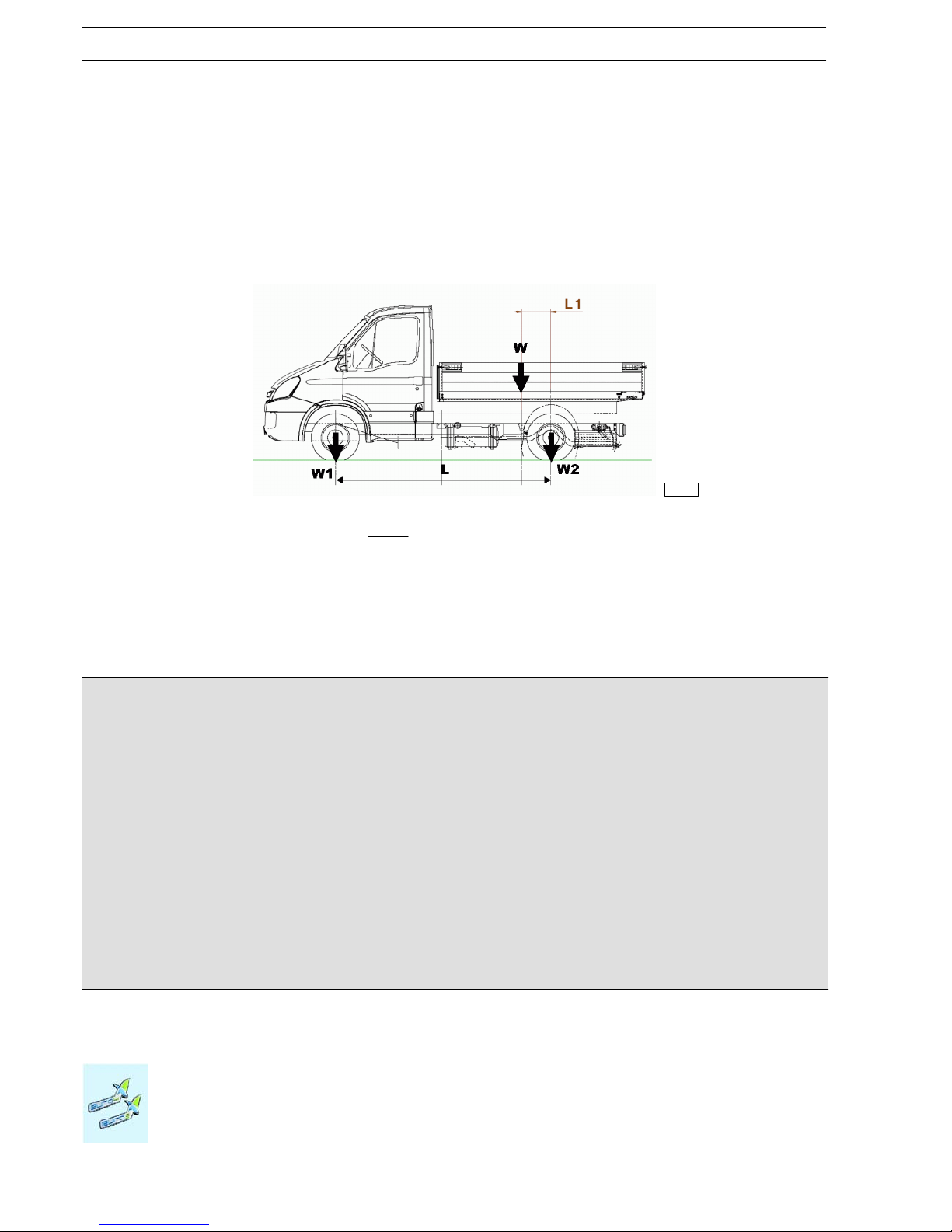
1.13.2 Determining the Centre of Gravity of the Body and Payload
Positioning on the longitudinal plane
To establish the location of the centre of gravity of the body and payload the following examples below may be used as guidelines.
The technical documentation specific to each model (chassis cab drawing) givethe positions permitted wit h the vehicle in its standard
form. The masses and positioning of the single components of the vehicle are given in the chassis and weight distribution diagram.
respectively L1 = L −
W2 ⋅ L
W
102452
Figure 1.1
W = Body + payload (kg)
W1 = Body and payload acting on front axle (kg)
W2 = Body and payload acting on rear axle (kg)
L1 = Distance of the centre of gravity from the rear axle centre line (mm)
L = Wheelbase (mm)
L
1
=
W
1
⋅ L
W
Example of calculation of the load barycentre position
Consider a 40C13 vehi cle with a wheelbase of 3450 mm with:
1. GWW= 4200 kg (permitted maximum: 1900 kg on the front and 3100 kg on the rear)
2. KERB WEIGHT = 1955 kg (1340 kg on the front axle, 615 kg on the rear)
The permitted maximum load (body + payload) will be W = 4200 - 1955 = 2245 kg. Let us calculate the position of the center
of gravity in which the maximum permitted on the front axle is achieved. Let us assume an uniform distributed load .
In this case, out of 2245 kg. W
1
= 1900 - 1340 = 560 kg will affect the front axle, while the remaining W2= 2245 - 560 = 1685
kg will affect the rear axle.
Thus, the following will be obtained:
1. W
1
= 560 kg
2. L = 3450 mm
3. W = 2245 kg
L
1
=W1x L / W = 860 mm
The center of gravity of the load (Body + payload) must not be more than 860 mm far from the rear axle; o therwise, the front
axle would be overloaded.
Page 19
GENERAL SPECIFICATIONS
1-11
DAILY 4X4
Print 603.93.761 Base - May 2007
Dimensions and masses
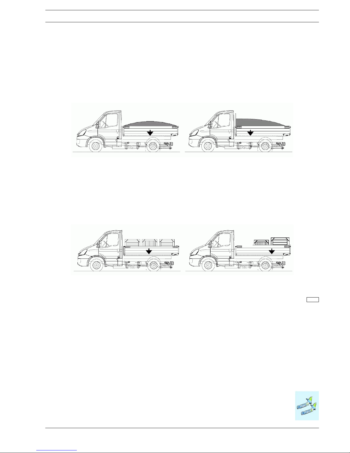
In order to determine the payload on the axles, it must be uniformly distributed except when the shape of the loading surface itself
entails a different distribution of the load.
Regarding any equipment, th e act ual position of the centre of gravity must be used.
When building bodies or containers, loading and unloading systems must be devised which preclude excessive variations in the
distribution of the load and/or excessive loads on the axles. Relevant instructions should also be given to the operator.
Uniform load distribution Uneven load distribution
Uniform load distribution Uneven load distribution
(beware of axle loads and minimum axle ratio)
102453
Figure 1.2
Figure 1.3
Page 20
1-12
GENERAL SPECIFICATIONS
D
AILY 4X4
Base - May 2007 Print 603.93.761
Dimensions and masses
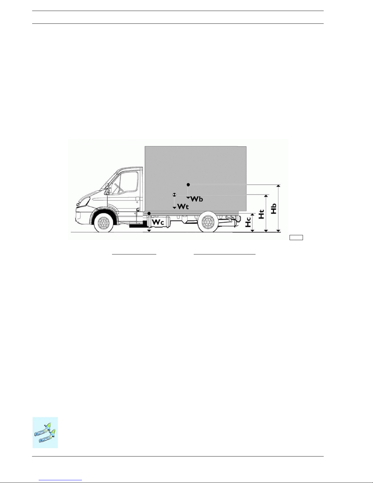
Height of the centre of gravity
The height of the centre of gravity of the chassis cab is given in the technical documentation specific to each model (chassis
drawing).
For testing the vehicle complete with superstructure, the bodybuilder must check that the height of the centre of gravity of the
equipment including the payload, or of the entire vehicle when fully loaded, falls within the maximum permitted values.
These limits are defined in compliance with the national or international regulations (e.g. as amended by the current EC braking
Directive) or requested by the Manufacturer to ensure good handling of the vehicle (e.g. transverse stability of the moving vehicle).
Figure 1.4
Verification with full load:
102454
Ht =
Wc . Hc + Wb . Hb
Wc + Wb
Hb =
(Wc + Wb) . Ht − Wc . Hc
Wb
Wc = Chassis cab vehicle kerb weight
Hc = Height of centre of gravity of chassis cab vehicle (laden condition)
Wb = Body and payload
Hb = Height of centre of gravity of body and payload in relation to ground
Wt = Vehicle weight when fully loaded
Ht = Height of centre of gravity of vehicle with full load
To check the vehicle with its body but no payload, use the above formula but for Ws use only the vehicle unladen weight (The
position for Hv will depend on the load and deflection of the suspension).
The height of the centre of gravity indicated in Table 2.6 represents values which are not to be exceeded for each given equipment
level. These values have been c alculated only in terms of the transverse stability of the vehicle and are applicable to a mid wheelbase.
Any other possible restrictive specification, e.g. braking regulation , should be taken into consideration.
The values given in Table 2.6 refer to the body with fixed payload. In versions where the payload tends to move sideways (e.g.
suspended loads, fluid loads etc.) especially when turning, higher dynamic transverse forces is generated which makes the vehicle
less stable. This must be taken into consideration when providing vehicle operating instructions or for possible reduction in the
height of the centre of gravity.
Page 21

GENERAL SPECIFICATIONS
1-13
DAILY 4X4
Print 603.93.761 Base - May 2007
Dimensions and masses
Using Stabiliser Bars
Supplementary stabilising or anti-roll bars, where available, spring reinforcements or the application of rubber components (in
compliance with point 2.11) may increase the height of the centre of gravity of the payload which must be defined as each occasion
arises. The modification must be carried out after careful consideration has been given to the specifications of the version, to the
wheelbase and to the distribution of the cross-stresses acting on the suspension both at the front and at the rear of the vehicle.
It must be borne in mind that it is often advisable to modify the rear axle only since a modified front axle would give the driver a
false sense of stability making it more difficult to perceive the safety limits. Modification to the front axle may be made where the
load is positioned behind the cab (e.g. crane) or where the superstructures are very rigid (e.g. van conversion).
1.13.3 Observing the Permitted Weights
All t h e limits specified on the IVECO documents must be complied with. It is essential t hat the maximum weight on the front
axle is not exceeded, under any load condition, so as to ensure the correct steering and braking characteristics regardless of the
road surface conditions.
Particular attention must be taken with vehicles where the load is concentrated on the rear overhang (e.g. cranes, tail lifts, trailers)
and to vehicles with short wheelbases and a very high centre of gravity.
Ensure transverse loads are properly distributed when positioning auxiliary components an d superstructures. A +4% variation on
the rated load (50% of load on the axle) is permissible for each wheel (for example: permissible load on axle 3000 kg; 1440 to 1560
kg allowed for each wheel side); in compliance with load allowed by tyres, without affecting braking properties and vehicle driving
stability.
Apart from different specifications for specific vehicles, the following may be taken to be the minimum weights for the front axle:
30% of the total vehicle weight (with uniformly distributed loads and w ith loads concentrated on the rear overhang).
The rear overhang of the body must be built in strict observance of the permitted axle loads, the minimum load required on the
front axle, the limitations in length, the positioning of any tow hook and of the rear under-run guard stipulated by the relevant
National and EC regulations.
Variations in the Permissible Weight
Special exceptions to the maximum permissible weights may be granted for particular applications for which, however, precise
limitations regarding the use will be imposed in addition to possible vehicle reinforcements.
Such exemptions, if they exceed the limits imposed by law, must be authorised by the Government Administrative Authority.
The request for authorisation must include:
- vehicle type, wheelbase, identification number, designated use;
- unladen weight on the axles (e.g. vehicles equipped with crane) including positions for the centre of gravity of the payload;
- proposals concerning the reinforcement of the vehicle components where necessary.
The reduction in the permissible weight on the vehicle (derating) may involve changing various components such as suspension,
brakes etc) and may require recalibration of the load sensing valve where one is fitted. In these circumstances necessary instructions
may be provided.
Page 22

1-14
GENERAL SPECIFICATIONS
D
AILY 4X4
Base - May 2007 Print 603.93.761
Instructions for the Correct Functioning of the Parts of the Vehicle and Accessibility for Maintenance
Instructionsforthe Correct F unctioningofthe Parts ofthe Vehicleand AccessibilityforMaintenance
1.14 Instructions for the Correct Functioning of the Parts of t he Vehicle
and Accessibility for Maintenance
As a rule, when modifying or installing any type of equipment, n o th ing must be altered which prevents the correct fu n ctioning
of assemblies and parts of the vehicle under all operational conditions.
For example:
- Ready access to all parts requiring inspection or maintenance and periodic servicing must be provided. In the case of closed body
types suitable opening doors must be provided.
- For tilting cabs, adequate space permitting tilting must be assu red. In the case of structures which involve the space above the
driver’s cab, adequate space for the passage of intake air must be guaranteed.
- Service access to chassis/driveline components must be retained. For instance repairing the gearbox or clutch must be possible
without necessitating the removal of major components of the added structure.
- The cooling system (radiator cowling, radiator, air passages, cooling circuit etc.), fuel supply (pump position, filters, pipe diameter,
etc.) and the engine air intake must not be altered.
- The anti-noise panels must not be altered or moved in order to prevent changes in the approved noise levels of the vehicle.
Should it be necessary to make openings (e.g. for the longitudinal runner of the body to pass through) these must be properly
closed off using material with inflammability and soundproofing characteristics equivalent to those used originally.
- Adequate ventilation of the brakes and battery case (especially in the case of vans) must be guaranteed.
- When positioning the mudguards and wheel arches, the rear wheels must be free to rebound even when used with chains.
- When the vehicle has been set up, for safety reasons, headlight attitude must be checked and adjusted as necessary. Perform
the adjustment ac cording to the instructions provided in the use and maintenance manual.
- In the case of parts which are supplied loose (e.g. spare wheel, chocks) it will be the responsibility of the bodybuilder to position
and secure them in an accessible and safe manner in compliance with possible national laws.
Page 23

GENERAL SPECIFICATIONS
1-15
DAILY 4X4
Print 603.93.761 Base - May 2007
1.15 Quality System management
For some time IVECO has been promoting Quality System development and trainin g for bodybuilders.
This is a requirement due not only to compliance with domestic and in ternational regulations on product liability, but also the growing
demand for increasingly higher quality levels. The creation of new forms of organization in the various sectors and the quest for
increasingly more advanced levels of efficiency.
IVECO believes it essential for bodybuilders to be equipped with an organization where the following are defined and available:
- Organization charts for functions and responsibilities.
- Quality system.
- Quality goals.
- Technical design documentation.
- Process and control phases with relevant resources.
- Product improvement plan, obtained also with corrective actions.
- After sales service.
- Staff training.
- Manufacturer liability documentation.
1.16 Vehicle maintenance
In addition to making the necessary checks on the outfit in keeping with customary working procedures, the bodybuilder shall
perform the checks specified in the “IVECO pre-delivery inspection” list, which can be obtained from the IVECO network, for t h e
aspects affected by the modifications performed.
Page 24
1-16
GENERAL SPECIFICATIONS
D
AILY 4X4
Base - May 2007 Print 603.93.761
Convention
Convention
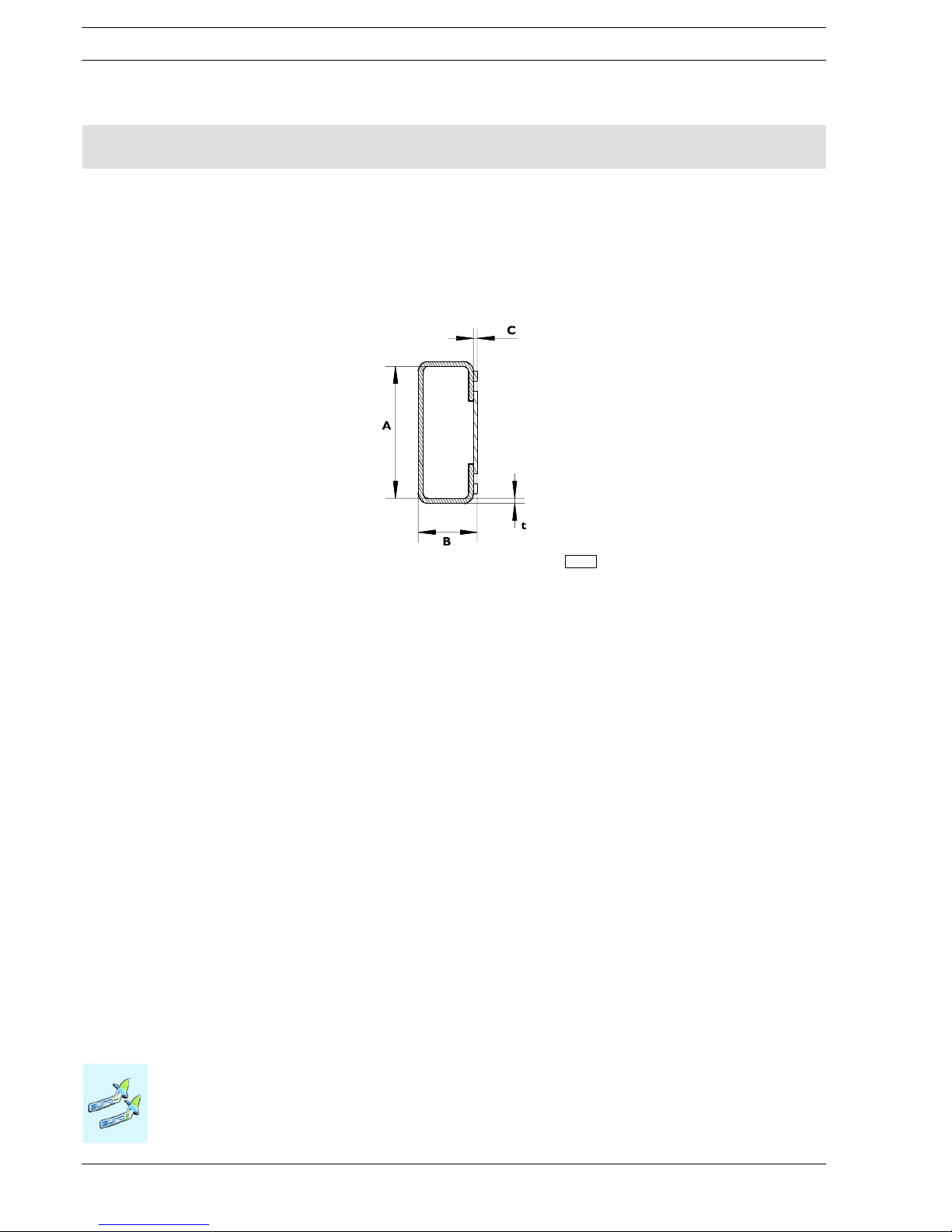
1.17 Conventions
In these bodybuilders instructions, the wheelbase is taken as the distance between the centreline of the first steering axle and
the centreline of the first rear axle (driven ornon-driven). This definition differs from the definition of wheelbase in th e CE Directives.
The rear overhang is taken as the distance between centreline of the last axle and the rear end of the chassis runner. For dimensions
A, B and t of the frame and counterframe section please refer to the figure below.
Figure 1.5
120360
Page 25

CHASSIS MODIFICATIONS
2-1
DAILY 4x4
Print 603.93.761 Base - May 2007
Index
Index
SECTION 2
Chassis modifications
Page
2.1 General instruct ions for chassis modifications 2-5
2.1.1 Specific Precautions 2-5
2.2 Protection against Rust and Painting 2-7
2.2.1 Original components 2-7
2.2.2 Added or modified painted parts 2-10
2.2.3 Precautions 2-11
2.2.4 Exceeding the Limits 2-12
2.3 Drilling the Chassis 2-13
2.3.1 Screws and nuts 2-13
2.3.2 Characteristics of the material to be used when modifying the chassis 2-13
2.3.3 Stresses on the chassis 2-14
2.3.4 Welding the Chassis 2-15
2.3.5 Closing of existing holes 2-16
2.4 Modifying the Wheelbase 2-17
2.4.1 General Specifications 2-17
2.4.2 Authorisation 2-17
2.4.3 Consequences for steering 2-17
2.4.4 Effect on Braking 2-17
2.5 Modifying the Rear Overhang 2-18
2.5.1 Authorisation 2-18
2.6 Installing a Towing Device 2-18
2.6.1 General Specifications 2-18
2.6.2 Traditional towing hooks 2-19
2.6.3 Hook types 2-22
2.6.4 Lowered Rear Cross Member 2-22
2.7 Installing a Supplementary Axle 2-24
2.8 Modifying the Drive Line 2-24
2.8.1 Permitted lengths 2-24
Page 26

2-2
CHASSIS MODIFICATIONS
D
AILY 4x4
Base - May 2007 Print 603.93.761
Index
Page
2.8.2 Determining Driveshaft Positions 2-27
2.9 Modifications of the engine air intake and exhaust system 2-29
2.9.1 Intake 2-29
2.9.2 Engine exhaust 2-29
2.10 Modification of the Engine Cooling System 2-30
2.11 Work on the Suspension 2-31
2.11.1 General Specifications 2-31
2.12 Heating/Air conditioning system modifications 2-32
2.12.1 Installation of a Supplementary Heating System 2-32
2.12.2 Installing an Air-Conditioning System 2-33
2.13 Cab Modifications 2-34
2.13.1 General Specifications 2-34
2.13.2 Roof Panel Modifications 2-35
2.13.3 Occupant protection 2-37
2.14 Changing the Size of the Tyres 2-38
2.15 Modifications to the Braking System 2-39
2.15.1 General remarks 2-39
2.15.2 Brake pipes 2-39
2.15.3 Fitting pipes on the vehicle 2-40
2.15.4 Instructions for adjusting the braking load proportioning valve 2-43
2.16 Electrical System: Modifications and Drawing-Off Power 2-48
2.16.1 Earth points 2-50
2.16.2 Electromagnetic compatibility 2-56
2.16.3 Additional equipment 2-63
2.16.4 Current drawing 2-66
2.16.5 Additional Circuits 2-74
2.16.6 Operations to adjust overhang 2-75
2.16.7 Provision for trailer 2-75
2.16.8 Side Marker Lights 2-78
2.17 Repositioning Parts and Mounting Auxiliary Assemblies and Equipment 2-80
Page 27

CHASSIS MODIFICATIONS
2-3
DAILY 4x4
Print 603.93.761 Base - May 2007
Index
Page
2.18 Retarder Installation 2-82
2.19 Modifications to the Rear Underrun 2-82
2.20 Rear mudguards and wheel boxes 2-83
2.21 Mudflaps 2-83
2.22 Side Guards 2-83
2.23 Chocks 2-85
Page 28

2-4
CHASSIS MODIFICATIONS
D
AILY 4x4
Base - May 2007 Print 603.93.761
Index
Page 29
CHASSIS MODIFICATIONS
2-5
DAILY 4x4
Print 603.93.761 Base - May 2007
General instructions for chassis modifications
2222.2
General i nstruction sf orch assis modif ications
2.1 General instructions for chassis modifications
Particular attention must be given to the following points:
- Welding to the bearing structures of the chassis is explicitly prohibited (with the exception of the items described at points
2.3.4, 2.4 e 2.5);
- Holes in the flanges of the side members are not permitted (except for the items described at point 2.3.4);
- Where riveted connections exist and can be modified as explained below, these can be replaced by flanged-head screws and
nuts of min. c lass 8.8 or by hex screws of the next greater diameter and self locking nuts. Screws greater than M12 must not
be used (max. diameter of hole 13 mm) unless otherwise specified.
- In cases where t h e original joints were detached and rejoined with bolts it is forbidden to reuse the same bolts. In th is event
and when rivets are replaced with bolts, the bolt torque must be checked after the vehicle has been driven approximately 500
÷ 1.000 kms.
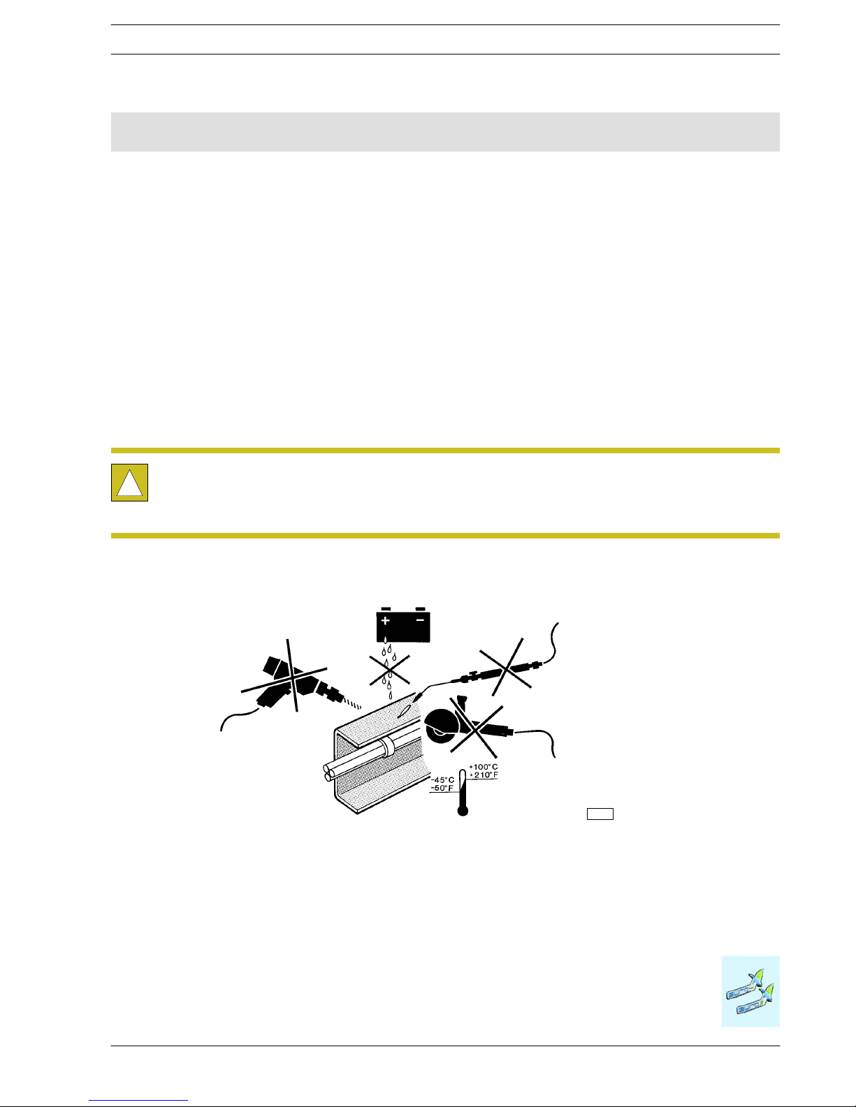
2.1.1 Specific Precautions
!
During the welding, drilling, grinding and cutting operations when working in the proximity
of brake lines and particularly if these are of plastic material or electric wiring, care must be
taken to ensure their protection. Where necessary they should be removed (comply with the
provisions given at points 2.15 and 2.16).
Figure 2.1
91444
Page 30

2-6
CHASSIS MODIFICATIONS
D
AILY 4x4
Base - May 2007 Print 603.93.761
General instructions for chassis modifications
Regarding the electrical equipment remember to:
a) Take precautions concerning the alternator and the electrical/electronic components. In order to avoid damaging the diode
rectifier, never disconnect the batteries (or open the isolator) when the engine is running.
If the vehicle has to be tow started make certain that the batteries are connected. Should it be necessary to quick charge
the batteries, disconnect them from the vehicle circuit.
In order to run the engine with external means and in order to avoid current peaks which might damage the electric/electronic components, do not use the ”start” function in conjunction with external charge devices if such devices are equipped
with this function. Starting will have to be carried out only with the external battery trolley ensuring correct polarity.
b) Checking the earth connections.
As a general rule the original earth connections of the vehicle must not be changed. If it is necessary to move these connections or to implement further earth points use the existing holes on the chassis as far as possible and:
- Remove, mechanically, and/or with an appropriate chemical product, th e paint on the chassis side and on the terminal side
creating a resting plane free from indentations or ridges.
- Apply appropriate high conductivity paint between the cable terminal and the metal surface (e.g. galvanizing paint IVECO
Part number 459622 by PPG).
- Connect the earth cables within 5 minutes from the application of the paint.
Do not use the IVECO standardised M1 (battery earth connection) M2, M8 (earth connection for starter motor depending on the
driving position) points for the earth connections for control switches (e.g. sensors or low absorption devices): See IVECO Workshop manuals.
With regard to the electronic devices, avoid linking earth connections between the devices; only use single wireearths with optimised
lengths (as short as possible).
c) Electric wiring
For further information regar ding the braking and electronic system, refer to point 2.15 and 2.16.
Page 31

CHASSIS MODIFICATIONS
2-7
DAILY 4x4
Print 603.93.761 Base - May 2007
Protection against Rust and Painting
Protection agai nst Rust and Painti ng
2.2 Protection against Rust and Painting
All components installed on chassis must be painted as per Sta Iveco 18-1600 Colour IC444RAL 7021
brightness 70/80 shore.
NOTE
2.2.1 Original components
In Table 2.1 details the operations for protecting and painting the components of the original vehicle (Table 2.3 for painted parts,
Table 2.2 for non-painted or aluminium parts).
Table 2.1 - Protection category - STD 18 - 1600 (Schedule I)
Class Parts requirements Specific examples affected
A Parts in direct contact with atmospheric agents
Body - Door mirrors- Windscreen wipers - Aerodynamic
kit metal structure - sun blind metal structure - Metal
bumpers - Cabattachment lock- Door stopdevice - Body
fasteners (screws,bolts, nuts, washers), etc.
B
B2
Parts in direct contact with atmospheric agents.with
mainly structural characteristicsin direct view.
Frame an d parts, includingfasteners.
Parts beneath grille (category B).
Exterior cab steps.
B1
mainlystructuralcharacteristicsindirectview
.
Only for rear axles and axles
C
Parts in direct contact with atmospheric agents.not in
direct view.
Engine and parts
D Parts not in direct contact with atmospheric agents.
Pedals - Seat reinforcements - Fasteners - etc., fitted inside
cab.
Parts must be supplied only with cataphoretic coating or rustproofing (Schedule III). The enamel will
be appliedduring the frame finishing stage.
NOTE
Page 32

2-8
CHASSIS MODIFICATIONS
D
AILY 4x4
Base - May 2007 Print 603.93.761
Protection against Rust and Painting
Table 2.2 - Various unpainted and aluminium parts and components - STD 18 - 1600 (Schedule IV)
IVECO
Class
Typeof
p
rotection
IVECO
standard
A B-B1-B2 C D
Stainless steel ¡ 18-0506 yes - - -
DAC 320-8
- - -
DAC 500-8
y
es
- -
D
acr
ome
t
DAC 320-5
- - -
Dacrome
t
(H)
DAC 500-5
18-1101
- - -
(
)
DAC 500-5 PL -
yes
Category B1
wheel studs
- -
GEO
321-8-PM
yes -
GEO 321-5
Geomet
(HHH)
GEO
321-5-PM
18-1101
-
yes
- -
GEO
321-5-PL
yes
Category B1
wheel studs
Fe/Zn 12 III
(yellow)
- - yes yes
Fe/Zn 12 V
(olive green)
- - -
Zinc coating
(H)
Fe/Zn 25 V
(olive green)
-
- -
Fe/Zn 12 III S
(yellow)
18-1102
-
y
es
- -
Fe/Zn 12 V S
(olive green)
- - -
Zinc coating
Fe/Zn 12 II - - yes yes
Zinccoating
(HH)
Fe/Zn 12 IV S - yes - -
Anodic
oxidation
18-1148 yes
A
lumini
um
Painting
See
Schedule III
yes
yesyesy
es
(H) Hexavalent chromium coatings.
(
HH) Hexavalent chromium-free coatings.
(
HHH) Chromium-free coatings.
¡ Matching with other metals must not generate battery effects.
Page 33

CHASSIS MODIFICATIONS
2-9
DAILY 4x4
Print 603.93.761 Base - May 2007
Protection against Rust and Painting
Table 2.3 - Painted parts - STD 18 - 1600 (Schedule III)
Classes
D
escr
i
pti
on ofthecycle
p
h
ase
A B § B1 ¤ B2 C D
Sanding/sandblasting -
MECHANICALCLEANING
Brushing
yes L - yes L yes L yes L
SUPERFICIAL
¡
Sandpapering
yesL
PRETREATMENT
Iron phosphatation (only for
non-precoated ferrous materials)
-
yes L - yes L yes L yes L
PRETREATMEN
T
Zinc phosphatation l yes
yesLyesLyesLyes
L
High thickness (30-40 µm) yes ©
yes L
CATAPHORESIS Medium thickness (20-30 µm) yes ¢
y
es L
-
yes
L
¥
y
es L
yes •
Acrylic top coat (>35 µm) -
¥-¨
Bicomponent (30-40 µm) yes - yes
yes L
RUSTPROOFIN
G
Monocomponent (30-40 µm)
-
- yes yes
yes
L
¨
CHIP-RESISTANT PRIMER
Mono (130 °C)
or bicomponent (30-40 µm)
yes ¢ - - - - -
Mono (130 °C)
or bicomponent (30-40 µm)
yes
yes L -
ENAMEL Powders (40-110 µm) yes £
yes
L
- yes L
y
es L
¦
Single component, low temperature
(30-40 µm)
- - yes
¦
¡ = Carry out operation in presence of shearing burrs, oxidation, welding swarf, laser-cut surfaces.
© = Two-coat body cycle.
¢ = Three -coat body cycle.
£ = As an alternative to single or dual component enamel only for b ody parts (windscreen wipers. Rear view mirrors etc.).
¤ = Only for rear axles and axles.
¥ = Excluding parts that cannot be submerged in pretreatment or paint baths because this would affect their operation (e.g.: mechanical parts).
¦ = Colour is specified on the drawing by means of an IC
§ = For fuel tanks in ferrous sheet metal or precoated.
¨ = Only parts to be fitted on engine.
= Parts that cannot be treated with cataphoresis (see ¥).
l = For galvanised or aluminium panels, use special phosphating treatments.
L = Alternative products and cycles for the same class, as long as they are compatible with the part being treated.
Page 34

2-10
CHASSIS MODIFICATIONS
D
AILY 4x4
Base - May 2007 Print 603.93.761
Protection against Rust and Painting
2.2.2 Added or modified painted parts
All parts of the vehicle (cab, chassis, bodywork, etc.) which are added or subjected to modification must be protected from rust
and corrosion.
There must be no unprotected areas on ferrous materials.
Table 2.4 (painted) and Table 2.5 (unpainted) show the minimum treatments requir e d for modif ie d or added components when
it is not possible to provide the same protection as that used on IVECO original components. Different treatments are allowed
on condition that the same level of protection against rust and corrosion is guaranteed.
Never use powder enamels directly after degreasing.
Parts in light alloy, brass and copper must not be protected.
Table 2.4 - Added or modified painted parts
Class
D
escr
i
pti
on ofthecycle
p
h
ase
A-B-D(1)
Mechanicalsur
f
ace cleanin
g(includ
ingther
emovalo
f
bur
rs/
rust
Brushing/sanding/sand blastin
g
and cleaningof modifiedpa
r
ts)Brushing/sanding/sandblastin
g
Pre-treatment Degreasing
Anti-rust Bicomponent (30-40µm) (2)
Paint Bicomponent (30-40µm) (3)
(1) = Modifications to rear axles, front axles and engine (Classes B1 and C) are not allowed.
(2) = Preferably epoxy.
(3) = Preferably polyurethane.
Table 2.5 - Added or modified unpainted and/or aluminium parts
Class
Typeof
p
rotection
A—B(1) D
Stainless steel
-
Dacromet (1)
y
es
-
Zinc treatment (1) - yes
(1) = Hexavalent chromium-free.
Page 35

CHASSIS MODIFICATIONS
2-11
DAILY 4x4
Print 603.93.761 Base - May 2007
Protection against Rust and Painting
2.2.3 Precautions
Suitable precautions must be taken to protect those parts whose preservation and operation could be damaged by paints such
as:
- rubber or plastic pipes for th e air and hydraulic installations;
- gaskets, parts in rubber o r plastic;
- flanges of the transmission shafts or power take-offs;
-radiators;
- shock absorber and hydraulic or air cylinder rods;
- drainage and bleeder valves (mechanical components, air tanks, cold starting heater plug pre-heating tanks etc.);
- fuel sediment filter;
- nameplates and logos.
With particular regard to the engine and its electric and electronic components, adequate precautions shall be taken to protect:
- on the whole engine and vehicle wiring, including earth contacts;
- on all connectors on sensor/actuator side and wiring side;
- on all sensors/actuators, on flywheel, on flywheel rev sensor bracket;
- on the whole diesel fuel system pipes (plastic and metallic);
- on complete diesel fuel filter base;
- on control unit and control unit base;
- on the whole soundproofing c over inner side (injectors, rail, pipes);
- on common rail pump including regulator;
- on vehicle electric pump;
- on tank;
- on front belt circuit and relevant pulleys;
- on power steering pump and relevant piping.
If the wheels are removed, protect the contact surfaces on the hubs, avoid increasing the thickness and especially avoid the build-up
of paint on the connecting flanges of the wheel disks and resting points of the fixing nuts.
Ensure that the disc brakes are adequately protected.
The electronic components and modules must be removed.
!
When the painting operation is to be completed by oven drying (max. temp. 80ºC), all parts which may
be damaged by exposure to heat, must be removed.
Page 36

2-12
CHASSIS MODIFICATIONS
D
AILY 4x4
Base - May 2007 Print 603.93.761
Protection against Rust and Painting
2.2.4 Exceeding the Limits
In case of special transport with considerable h i gh centre of gravity (e.g. special body versions, advertising vehicles, etc.), from
a technical point the values shown in the table may be exceeded, provided the vehicle is driven carefully (e.g. low speed, gradual
running direction changes, etc.).
Table 2.6 - Maximum heights in relation to the centre of gravity of the payload and cornering stability
Models
Max. height (approx.) of centre of gravity of payload
(include. body and equipment) in relation to the
ground (mm)
- -
Page 37

CHASSIS MODIFICATIONS
2-13
DAILY 4x4
Print 603.93.761 Base - May 2007
Drilling the Chassis
DrillingtheChassis
2.3 Drilling the Chassis
The frame must not be drilled.
When auxiliary units or components are to be applied to the frame, existing factory-made holes must be used and the followin g
instructions must be applied.
Positioning and sizes
If it is necessary to make holes in the frame, it is compulsory to ask IVECO for authorisation.
2.3.1 Screws and nuts
In general, use connectors of the same type and class as those for similar fixings on the original vehicle (Table 2.7).
As a general rule, materials of class 8.8 are recommended. Class 8.8 and 10.9 screws must have been hardened and tempered. For
applications of diameter
± 6mm, stainless steel parts are recommended. Approved finishes are Dacromet and zinc coating, as detailed
in Table 2.2. A Dacromet finish is not recommended if the screws are to be subjected to welding. If space allows, use screws and
nuts with flanged heads . Use self-locking nuts. Nuts must be tightened using a torque wrench set to the correct torque setting for
the fixing.
Table 2.7 - Classes of resistance for screws
Class of resistance Usage
Tensile strength
(N/mm
2
)
Yield point
(N/mm
2
)
4 Non-load bearing screws 400 320
5.8 Low resistance screws 500 400
8.8
Medium resistance screws
(cross members, cleat plates,
brackets)
800 640
10.9
High resistance screws
(spring supports, stabilizer
bars and shock absorbers)
1000 900
2.3.2 Characteristics of the material to be used when modifying the chassis
When modifying the chassis of the vehicle, and in applications which reinforce the side membe r s directly, the mater ia l used must
correspond in quality (Table 2.8) and thickness (Table 2.9) to that of the original chassis.
Should it not be possible to source materials of the thickness indicated, the next superior standard thickness may be used.
Table 2.8 - Materiale da utilizzare nelle modifiche del telaio Standard IVECO 15-2110 e 15-2812
Steel name
Tensile strength
(N/mm
2
)
Yield point
(N/mm
2
)
A5 elongation
IVECO FEE490
Europe S355J0W
Germany
QSTE500TM -
S355J0W
610 490 23%
UK S355J0W
Page 38

2-14
CHASSIS MODIFICATIONS
D
AILY 4x4
Base - May 2007 Print 603.93.761
Drilling the Chassis
Table 2.9 - Daily: truck chassis dimensions, section and thickness
Class Type
Wheelbase
[mm]
Chassis rear
overhang
[mm]
AxBxt
wheelbase area
side member
section [mm]
AxBxt
rear overhang area
side member
section [mm]
3050 801
35S18
W-55S18Wt
ruck
3400 962
134x60x5134x60x
5
2.3.3 Stresses on the chassis
Do not exceed the following stress values under static conditions:
Table 2.10
Range Permitted static stress on the chassis (N/mm2) σ amm.
Off-road use
Daily 4x4 100
When prescribed by national regulations, the bodybuilder must check that the stress limits are not exceeded.
Welding activity will cause a deterioration in the characteristics of the material. Therefore, when checking the stresses in thermicallymodifie d zones, consider a reduction of approx. 15% of the resistance characteristics.
Page 39

CHASSIS MODIFICATIONS
2-15
DAILY 4x4
Print 603.93.761 Base - May 2007
Drilling the Chassis
2.3.4 Welding the Chassis
All frame welding must be carried out after authorisation from IVECO.They must then be carried
out scrupulously following the instructions given below.
NOTE
!
Welding operations must only be carried out by specialist, trained personnel, using suitable equipment
and in a perfectly workmanlike manner (see norms EN 287). Any intervention on the system not carried out as per instructions provided by IVECO or carried out by unskilled staff, might severely damage
the on-board systems, thus adversely affecting vehicle operation safety and efficiency and causing damages not covered by guarantee contract.
In case of arc welding, strictly follow instructions below in order to protect electric units and ECUs:
- before disconnecting power cables, check for no loads engaged;
- in case an electric switch is installed (main contactor) wait for cycle end;
- disconnect negative power pole;
- disconnect positive power pole without connecting it to ground and DO NOT short circuit it with negative pole;
- disconnect ECUs connectors, operate carefully and do not touch ECU connector pins;
- In case of welding next ECU, disconnect it from vehicle;
- connect welding machine ground directly on part to be welded;
- protect plastic material pipes against heat sources and disassemble, if required:
- in case of welding near leaf springs or air springs against welding spatters, carefully protect surfaces;
- avoid electrode or gun contact with spring leaves;
Operations for welding preparation
As part of the procedure it will be necessary to remove the paint and deoxidise the parts of the chassis that are affected by the
welding operation as well as those parts which may have to becovered by possible reinforcements. When work has been completed
the modified part must be protected with adequate rustproofing (see point 2.2.2).
a) Cut the side members with a diagonal or vertical cut. (We recommend that the diagonal cut be used particularly for the section
between the wheelbase) Cuts are not permitted in areas in which the profile of the side member as well as the chassis width
change or in those where there is a high concentration of stresses (e.g. spring brackets). The cuts must not be made through
the holes present in the side member (see Figure 2.2).
91446
Figure 2.2
Page 40

2-16
CHASSIS MODIFICATIONS
D
AILY 4x4
Base - May 2007 Print 603.93.761
Drilling the Chassis
b) On the inner side of the side member give the parts th at are to be joined a V-shaped chamfer of 60° along the entire length
to be welded (see Figure 2.3).
91447
Figure 2.3
c) Arc weld in stretches using carefully dried basic electrodes. The recommended electrodes are:
For S 500 MC (FeE490: QStE 500TM)
Diameter of the electrode is 2.5 mm, cu rrent intensity approx. 90A (max. 40A for each millimetre of diameter of the electrode).
Using MIG-MAG welding use a welding rod with the same characteristics as the material to be welded (diameter 1 to 1.2 mm).
Recommended welding rod: DIN 8559 - SG3 M2 5243
gas DIN 32526-M21 or DIN EN 439
If FeE490 is used at very low temperatures, we recommend:
PrEN 440 G7 AWS A 5.28 - ER 80S - Ni 1
gas DIN EN439-M21
Avoid current overloading. Welding must be free from marginal cuts and waste material.
d) Repeat the operation on the reverse side by welding as detailed in point c).
e) Allow the side members to cool slowly and u niformly. Cooling by air, water or other means is not permitted.
2.3.5 Closing of existing holes
If, when making new holes, the existing holes are found to be too closethese may be closed up bywelding. To ensure the success
of this operation the outer edge of the hole should be chamfered and copper plate used for the inner part.
For holes with a diameter of over 20 mm, chamfered plugs may be used, welded on both sides.
Page 41

CHASSIS MODIFICATIONS
2-17
DAILY 4x4
Print 603.93.761 Base - May 2007
Modifying the Wheelbase
ModifyingtheWheelbase
2.4 Modifying the Wheelbase
2.4.1 General Specifications
It is only possible to alter the wheelbase after obtaining specific approval from IVECO.
2.4.2 Authorisation
Provided the chassis converter gives sufficient guarantees from the technological and control point of view (qualified personnel,
adequate operating processes, etc.).
Conversion must be carried out performed in compliance with these instructions by making the necessary changes and adjustments
and taking the appropriate precautions (e.g., determining whether ECU parameters need updating, rearranging the exhaust pipes,
ensuring compliance with specific load limits on the rear axle, etc.), by taking into due account the requirements specified for the
original wheelbase lengths.
2.4.3 Consequences for steering
In general, changesto the wheelbase affect steering specifications. Each operation is directly linked to th e authorisation requested
from IVECO.
2.4.4 Effect on Braking
In general, changes to the wheelbase affect braking specifications. Each operation is directly linked to the au th orisation requested
from IVECO.
Page 42

2-18
CHASSIS MODIFICATIONS
D
AILY 4x4
Base - May 2007 Print 603.93.761
Modifying the Rear Overhang
ModifyingtheRe ar Overhang
2.5 Modifying the Rear Overhang
2.5.1 Authorisation
Rear frame lengthening, as well as shortening to the shortest standard value for each model, must be specifically authorised by
IVECO.
2.6 Installing a Towing Device
2.6.1 General Specifications
Without prior authorisation, the installation of a tow-hook is permissible only on those cross members which are intended for
that use and on those vehicles which IVECO has intended for towing a trailer.
The subsequent installation of a tow hook in vehicles for which the installation of a tow hook was not originally contemplated, must
be authorised by IVECO.
In addition to the permissible towing weight, the authorisation will specify all other possible specifications that are to be adhered
to such as the use of the vehicle, the transmission ratio, the type of braking system as well as possible specifications concerning
reinforcements to be applied to the rear cross member or the necessity for employing specially intended cross members.
In trailers with one or more axles close together (centre axle trailers), considering the stress resulting in particular from t he vertical
dynamic load to which the rear cross member is subjected, the instructions given in point 2.6.2 must be taken into account.
!
The tow hook must be appropriate for the permitted loads and of the type approved by national laws.
Since tow hooks are important to vehicle driving safety (in some countries they must be specifically
certified) they must not be modified in any way.
When mounting the tow hook to the cross member, the specifications of the hook manufacturer as well as the limitations imposed
by current standards - such as minimum space required for the brake and electrical connections the maximum distance between
the swivel hook axis and the rear edge of the body - must be respected.
The siz e of the h ook attachment flange does not coincide with the holes on the vehicle rear beam, modification of the drilling on
the beam may be authorised in specific cases after applying appropriate reinforcements.
The bodybuilder is obliged to construct and fit the superstructure to make the necessary manoeuvres and control of the attachment
possible without impediment or hazards.
The trailer drawbar must be free to move.
Page 43

CHASSIS MODIFICATIONS
2-19
DAILY 4x4
Print 603.93.761 Base - May 2007
Modifying the Rear Overhang
2.6.2 Traditional towing hooks
S) Choice of hook for traditional trailers
The reference dimension for choosing the type of hook is defined by value D calculated as defined below.
116773
Figure 2.4
Free area for towing hooks
A towing hook may be fitted, without obtaining prior approval only on crossmembers provided for this purpose and to vehicles
on which IVECO provides for a towing hook to be installed.
The installation of a towing hook on vehicles which IVECO does not provide a towing hook installation then authorisation from
IVECO must be obtained before any installation is carried out.
The towing h ook must be chosen on the basis of the following typical values:
TxR
(T + R)
D = 9.81 x
D = Representative value of the hook class (kN).
T=Maximummassoftractor,int.
R = Maximum mass of trailer, in t.
Page 44

2-20
CHASSIS MODIFICATIONS
D
AILY 4x4
Base - May 2007 Print 603.93.761
Modifying the Rear Overhang
S) Towhook for mid-axled trailers
The use of central axle trailers implies the use of t ow hooks suitable for this purpose.
The values of the trailer loads and of the permissible vertical loads are contained in the technical documentation of the manufacturer
of the tow hook or on the production data plate (e.g. DIN 74051 and DIN 74052).
There are also tow hooks with special type approval, whose values are greater than the ones mentioned in the above st andards.
These hooks may in any case be subjected to restrictions depending on t h e trailers used (e.g. drawbar length). In addition this can
imply that the rear cross member should be further reinforced and a subframe runner of larger size be fitted.
- mobile connection with the towing vehicles takes place via a towing device.
- The drawbar is not connected to the frame so that it is free to move and therefore able to transmit vertical torques.
- Depending on its construction, part of the overall weight will be borne by the towing vehicle.
- For mechanical attachment devices designed for mid-axled trailers, the Dc, S and V values are defined by the followingequations:
Dc = g ⋅
(T ⋅ C)
(T + C)
= (kN)
V = a ⋅
X
2
l
2
⋅ C(kN)
D = representative value of the class of jaw (kN). This is defined as the technical reference force for the horizontal force between the towing vehicle and
the trailer;
g = acceleration due to gravity (m/s
2
);
T = maximum weight (in tonnes) of the towing vehicle;
T+S = maximum weight (in tonnes) of the towing vehicle + the vertical load of a trailer with a centre axle;
R = maximum weight (in tonnes) of the trailer;
S = value of the static vertical load (in tonnes) which, in static conditions, is transmitted to the point of attachment.
Smustbe≤ 0,1 ⋅ R ≤ 1000kg;
C = sum of the maximum axle loads (in tonnes) of the trailer with a centre axle at maximumload. It is equal to the maximumweight of the trailerwith acentre
axle less the static vertical load (C = R - S);
V = value V of the intensity of the theoretical dynamic vertical force;
a = for the equivalent acceleration at the point of attachment, as a function of the rear suspension of the towing unit, use the following values:
-a=1.8m/s
2
for air suspension;
-a=2.4m/s
2
for other suspension types;
X = length of the load surfaces (m);
l = theoretical length of the drawbar (distance between the centre of the drawbar towing eye and the centre line of the trailer axle (m));
X
2/l2
≥ 1 if the result is less than 1, use the value 1.
Example for calculating the class of towing gear for trailers with a centre axle
Let us consider a 65C15 vehicle with maximum weight 6250 kg that is to be used to tow a mid-axled trailer weighing
3500kg with S = 250 kg, lo ad surface length of 5m and theoretical drawbar length of 4m.
Therefore, from the data
1. S = 0.25 t
2. C = R — S = 3.5 - 0.25 = 3.25 t
3. (T + S) = 6.25 + 0.25 = 6.5 t
4. X
2/l2
=25/16=1.5
we obtain:
D
c
= 9.81 x (6.5 x 3.25) / (6.5 + 3.25) = 21.3 kN, and V = 1.8 x 1.5 x 3.25 = 8.8 kN
Page 45

CHASSIS MODIFICATIONS
2-21
DAILY 4x4
Print 603.93.761 Base - May 2007
Modifying the Rear Overhang
Towed vehicle equipped with a towin g device that cannot move in a vertical direction (in relation to the trailer) and in which
the axle or axles are arranged about the vehicle centre of gravity (under uniform load) so that only a small vertical load no greater
than 10% of the maximum trailer load or than 1000 kg, if lower, is transmitted t o the vehicle (lower value applies).
Mid-axled trailers are therefore subgroups of trailers with rigid drawbars.
116774
Figure 2.5
Length of trailer work surface and theoretical length of crossbar
The use of trailers with centre axles (rigid tow bartrailers with single or tandem axles), with respect to articulated tow bartrailers,
entails an increase in bending stress on the rear chassis overhang as well as an increased torsional stress of the rear towing cross
member resulting from the vertical static and dynamic loads which the tow bar exert s on the hook (for example when braking or
on bumpy roads).
On vehicles for which t o wing of a trailer is permitted and in accordance with values laid down by IVECO for each model, towable
weights with mid-axled trailers and vertical loads on the drawbar may be defined on the basis of the size of the drilling flange present
on the vehicle rear beam (see Table 2.11).
With long rear overhangs, it may be necessary to adopt larger subframe sections than normal depending on the towable weights.
Table 2.11 - Approved towing hooks available
Maker Type Class D(kN) Dc(kN) V(kN) EC approval no.
Pommier 70-C/3 S 31 31 37.5 e 2*94/20*0062*00
The following table sh o ws S maximum admitted value for origin al towing cross member when towing a central axle trailer.
Model Maximum S (kN)
35S18W - 55S18W 100
Page 46

2-22
CHASSIS MODIFICATIONS
D
AILY 4x4
Base - May 2007 Print 603.93.761
Modifying the Rear Overhang
2.6.3 Hook types
S) Ball hooks
In fitting the ball hook, in accordance with the manufacturer’s instruction s, it is necessary to observe the guidelines laid down
by the national and international regulations (e.g., EC Directives).
If required, the installer will need to present the necessary documentation to comply with the requirements of the law.
The automatic hook for the truck version can also be fitted to the same crossmembers provided for the ball hook.
120361
Figure 2.6
S) Pin hooks (automatic)
These are to be fitted on th e truck version, subject to using a suitable cross member. Unless supplied directly by IVECO, they
will both need to have type approval in compliance with current standards. They must be in stalled ac cording to the instructions
provided by the respective manufacturers.
13-Pole connector
If not already fitted by IVECO, it can be retro fitted following the instructions given in point 2.16.7.
2.6.4 Lowered Rear Cross Member
If the type of trailer used requires that the tow hook be positioned lower than originallyintended, IVECO may issueauthorisation
for the original cross member to be lowered or for an additional cross member (of the original type) to be fitted in a lower position.
Figure 2.7 shows an example.
The installation of the new cross member in its new position must be carried out in the same manner as before, using the same
type (diameter and class) of bolt.
Page 47

CHASSIS MODIFICATIONS
2-23
DAILY 4x4
Print 603.93.761 Base - May 2007
Modifying the Rear Overhang
Example of towing beam reinforcement
Figure 2.7
119379
A device to prevent the bolts from loosening must be adopted for th e joints.
Remarks about the Payload
It is essential to check that the static load on the hook does not mean that the permitted loadon the vehicle rear axle is exceeded
and that the minimum weight adhering to the front axle is respected, as indicated under point 1.13.3.
Increasing the Towable Mass
For those vehicles which IVECO regards as suitable for towing a trailer, a request may be submitted to evaluate the possibility
of authorising a towable mass exceeding that which is normally permitted.
Such authorisation will include the conditions that must be complied with and, where necessary, specifications concerning modifications and work to be carried out on the vehicle.
These include possible reinforcements to the standard cross member (see Figure 2.7), the instructions for installing a reinforced cross
member when available, and those on the brake system to be made.
The tow hook must be suitable for the new use. Its connecting flange must match that of the cross member.
To fasten the cross member to the chassis frame, preferably use flanged head nuts and bolts o r hex head screws of minimum class
8.8. Use self-locking nuts.
Rating plates
Some countries require a plate to be fitted, near the towing device, giving the maximum permitted towable weight and vertical
load. If not already fitted, this must be done by the bodybuilder.
The body builder shall also take care that the above plate is properly fitted.
Page 48

2-24
CHASSIS MODIFICATIONS
D
AILY 4x4
Base - May 2007 Print 603.93.761
Installing a Supplementary Axle
InstallingaSupplementaryAxle
2.7 Installing a Supplementary Axle
Supplementary axles are not approved for use on the vehicle.
2.8 Modifying the Drive Line
Following the modification of the wheelbase, work on the transmission, as a general rule, is carried out on the basis of the
transmission of a similar vehicle with approximately the same wheelbase. Th e maximum value of the inclinations of the propeller
shafts used for standard production vehicles is to be retained.This rule must also be applied w hen any modificationsto the suspension
and rear drive axle is made.
An all cases,contact IVECO and send them a diagram showing lengths and angles of the new proposed suspension for the necessary
authorisation.
The purpose of the specifications contained in this manual is to ensure the proper functioning of the transmission, to limit its noise
and to avoid the build-up of stress transmitted from the engine assembly. In n o way does this diminish the responsibility of the
bodybuilder for the work he has completed.
2.8.1 Permitted lengths
The maximum operating lengths obtainable for both the intermediate shaft sections and the sliding shafts ” LG” or ” LZ” (see
Figure 2.8) can be determined according to the external diameter of the tube existing on the vehicle and the maximum operating
rotational speed (see formula). These are specified in Table 2.14.
For t he propeller shaft length specified in Table 2.14. when the tube diameter is not sufficient, a new shaft section with the same
characteristics as the existing shafts must be used. As an alternative, in some cases transmission shaft with a larger diameter tube
can be used. The tube diameter required c an be determined in compliance w ith the required length and the maximum rotational
speed, directly from Table 2.14.
Figure 2.8
91505
Total Length
Total Length
Total Length
LZ Intermediate sections
LG Sliding sections
Page 49

CHASSIS MODIFICATIONS
2-25
DAILY 4x4
Print 603.93.761 Base - May 2007
Installing a Supplementary Axle
As far as sliding shafts are concerned, length”LG” is measured between the universal joint centres, with the sliding stub in the
intermediate position. Always check both sections LG and LZ.
The maximum working revs can be obtained using the formula below:
nG=
n
max
i
G
nG= maximum number of transmission shaft revs (r.p.m.)
n
max
= maximum number of engine revs (r.p.m.), refer to Table 2.12
i
G
= gearbox ratio in the fastest gear, refer to Table 2.13
Table 2.12 - Maximum number of engine revs
Engine Engine code (1) n
max
.18 F1CE0481H*C 3500
(1) = Check the engine code on the engine rating plate
Table 2.13 - Gearbox ratio with the fastest gear
Gearbox i
G
6S400 - 2840.6 0.8
Example of calculation of the maximum obtainable transmission length
Let us consider a 35C13 equipped with a ZF S5-200 gearbox. Let us assume you wish to use a propeller shaft LZ
with an outer diameter of 76.2 mm.
From the data below:
1. n
max
= 3600 rpm
2. i
G
=0.8
the following will be obtained:
n
G
= 3600 / (0.8) = 4500 rpm
This value corresponds to a maximum obtainable length of 1.400 mm.
The universal joints on the same shaft should not be rotat ed.
Page 50

2-26
CHASSIS MODIFICATIONS
D
AILY 4x4
Base - May 2007 Print 603.93.761
Installing a Supplementary Axle
The greater thickness of the tube depends on the class, i.e. on the torque that the original shaft has to transmit and on the design
of the driveline (torque, ratios of kinematic chain, power axle load).
A reference value for the thickness of the tube of a general validity cannot be given. When, for example, a tube of a larger diameter
is to be used, its thickness should theoretically be reduced until the torsional strength of the original tube is achieved. It should
however be noted that, to determine the thickness of the tube, the following points are to be taken into account: the size of the
male element of t he universal joint, the possible n ecessity of adapters and the sizes of the tubes available.
Therefore the thickness of the tube should be agreed upon as each occasion arises with the workshops authorised by the
manufacturers of the transmission shaft depending on its dimensions (i.e. siz e of the universal joint).
The minimum operating length (from flange to flange) must not fall below 600 mm for the sliding sections and 300 mm for the
intermediate sections.
Table 2.14 - Obtainable propeller shaft characteristics
1410 CRITICAL TRANSMISSION SPEED - PIPE ∅ 76.2 x 2.4 mm
Maximum permitted rotating speed (rpm)
Distancebetween the LV joint centres (mm)
1310 CRITICAL TRANSMISSIO N SPEED - PIPE ∅ 88,9 x 1,65 mm
Maximum permitted rotating speed (rpm)
Distancebetween the LV joint centres(mm)
1310 CRITICAL TRANSMISSIO N SPEED - PIPE ∅ 76,2 x 2,11 mm
Maximum permitted rotating speed (rpm)
Distance between the LV joint centres (mm)
117798
!
The above obtainable maximum lengths refer to the original shafts. Shorter shafts (-10%) shall be
provided for the sections resulting from the conversion.
Page 51

CHASSIS MODIFICATIONS
2-27
DAILY 4x4
Print 603.93.761 Base - May 2007
Installing a Supplementary Axle
2.8.2 Determining Driveshaft Positions
In the case of a drive line consisting of several sections, each shaft must be approximately the same length. As a general rule,
the difference in length between an intermediate and a sliding shaft (see Figure 2.9) must not exceed 600 mm; while between two
intermediate shafts the difference must be no greater than 400 mm. For sliding shafts there must be a margin of at least 20 mm
between the minimum working length and the fully closed length.
Complying with the useful travel, position the static arrangement in an area as central as possible.
120362
Figure 2.9
X˚ <10˚
If the wheelbase is lengthened considerably, it may be necessary to apply an extra propeller shaft between the reduction unit/transfer
box and rear axle. In this case, the angle between the various propeller shafts must be constant and contained within the maximum
limit envisaged in production (see Figure 2.9).
It is absolutely forbidden to move the transfer box.NOTE
The elastic supports must be fitted with supporting plates at least 5 mm thick (see Figure 2.10) joined to c ross members with
similar specifications to the IVECO specifications.
Fi
gur
e2.10
1. Intermediate shaft - 2. Support bracket - 3. Bearing plate - 4. Intermediate shaft support
102426
Page 52

2-28
CHASSIS MODIFICATIONS
D
AILY 4x4
Base - May 2007 Print 603.93.761
Installing a Supplementary Axle
The use of original drive line from IVECO is recommended for these modifications. Should this no t be possible however, hardened
steel tubes with a yield point of not less than 420 N/mm
2
(42 kg/mm2)maybeused.
Modifications to the universal joints are not permitted.
Whenever the transmission or part thereof, is modified, each modified section must be subjected to careful dynamic balancing.
!
Since transmission is important to vehicle driving safety, it should be borne in mind that any
modification to it must bear maximum operational guarantees. Only very specialised and transmission
manufacturer-certified companies should therefore be employed to carry out work of this kind.
Page 53

CHASSIS MODIFICATIONS
2-29
DAILY 4x4
Print 603.93.761 Base - May 2007
Modifications of the Engine Cooling System
Modificationsofthe EngineCooling System
2.9 Modifications of the engine air intake and exhaust system
2.9.1 Intake
The specifications o f the engine air intake and exhaust systems must not be altered without au thorisation by Iveco. Operations
carried out should not alter the vacuum levels (for the intake) and the original counterpressure levels (for the exhaust).
Table 2.15 - Maximum back-pressure permitted at the intake and exhaust, at the rated engine speed and full load
Engines Engine Code
Back-pressure at the
exhaust (kPa)
Minimum/maximum
back-pressure at the intake (kPa)
18 F1CE0481H*C 30 1.6 - 8.5
Any work done on the exhaust system of the vehicle requires that the vehicle be homologated again with regard to noise and smoke
wherever government regulations require it. The air intake must be positioned to avoid the intake of ho t air from the engine and/or
of dusty air or sn ow an d rain. The apertures for the intake of air w hich may have to be made in the bodies of vans, must have a
working surface of not less than two and a half times that of the master hose located upstream of the filter. These apertures (e.g.
openings in the grill) must be of such a dimension that they do not become obstructed. It is prohibited to alter the air filer or replace
the original filter with a lower air capacity unit. Modifications to the equipment (fuel injection pump, regulator, inject ors etc.) are
not permissible as this may alter the correct functioning of the engine and adversely affect the exhaust emissions.
2.9.2 Engine exhaust
Pipes must be laid as straight as possible, bend angles must not exceed 90° and radiuses must be at least 2.5 times the outer
diameter. Avoid constrictions and use effective cross-sections no smaller th an th e originals. Leave a big enough gap between the
exhaust piping and the electric system, plastic piping, spare wheel (minimum 150 mm), plastic fuel tank (minimum 100 mm), etc.
Lower values (e.g. 80 mm) may be approved if steel guard panels are used. Further reductions require the use of heat insulation
or the replacement of plastic pipes with steel pipes. Modifications to the silencer body are not permitted and neither is it permitted
to make changes to equipment (injection pump, regulator, injectors, etc.) that could impair efficient engine operation and affect exhaust gas emissions.
Page 54

2-30
CHASSIS MODIFICATIONS
D
AILY 4x4
Base - May 2007 Print 603.93.761
Modification of the Engine Cooling System
Modificati onof the Engi ne Cooling System
2.10 Modification of the Engine Cooling System
The properfunctioning of the original system, especially in connect ion with t he radiator, the free surface of the radiator and hoses
(dimensions and layout) must not be tampered with. In any case, whenever modifications must be made that entail work on the
engine cooling system (e.g., modifications to the c ab), the following points must be considered:
- the useful area for the passage of air for the cooling of the radiator must not be less than that which is available on vehicles with
the standard cab. Maximum venting of air from the engine compartment must be ensured and care must be taken - possibly
using shields or baffles - to avoid stagnant air pockets or back flow of air. The performance of the fan must not be altered;
- if it is necessary to re-position the hoses this must be done without affectin g the complete filling of the system (which must occur
at a continuous flow. without forming blockages at the mouth) or the normal flow of water. The maximum stabilising temperature
of the water must not be altered even under the most severe operating conditions;
- hoses must be located so that air pockets are not formed (i.e avoiding air traps and providing appropriate bleeding points) that
could hinder the circulation of water. So, it is necessary to check that the water pump primes immediately on starting the engine
and later operates with the engine idling (accelerate a few times, if necessary) even when the circuit is not pressurized. In addition
to this check that the delivery pressure of the water pump, when the engine is running under no load and at maximum RPM,
is not lower than 1 bar;
- always reinstall the radiator anti-clogging protection after making alterations to the engine cooling system.
Page 55

CHASSIS MODIFICATIONS
2-31
DAILY 4x4
Print 603.93.761 Base - May 2007
Modifications of the Engine Cooling System
Modificationsofthe EngineCooling System
2.11 Work on the Suspension
2.11.1 General Specifications
!
Company authorisation must be obtained to re-work the suspension systems and springs (e.g.
additional spring leaves, different cambering etc.) since these are important components for the
operation of the vehicle.
As a general rule no modification of the parabolic springs is permitted. On vehicles equipped with these springs, installation of
elastic rubber components may be authorised for special versions or operations in order to increase the stiffness of the suspension.
In very specific cases, and for specific uses, the possibility of adding an extra leaf to the parabolic spring may be evaluated. This
operation should be carried out only by specialised firms after approval from IVECO.
It is forbidden to fit a parabolic spring on one side and a semi-elliptic spring o n the other side on the same axle.
On vehicles equipped with a load apportioning valve (LAV) for the braking system, modification of the rear su spension requires
adjustment of this LAV valve (see point 2.15).
Modifications to the rear suspension
Changing the features of the rear spring (e.g., no. of leaves, spring rate etc.) requires adjusting the brake load apportioning valve
so as not to alter the vehicle’s braking performance. When work on the suspensions follows rather large changes in the permitted
loads on the axle(s) or the t otal weight o f the vehicle, it may be necessary to adapt the braking forces to permit compliance with
the requirements for the brake regulations in force. The necessary instructions will be given on the documentation issued by IVECO.
If the vehicle is equipped with the ABS system, no adjustment need be made.
If the modification of the specifications of the rear spring does not require changing loads on both axles and total weight, the brake
load apportioning valve must be adjusted by an IVECO dealer. So as not to alter the vehicle’s braking capacity, it is necessary to
observe the ground load / brake pressure ratio (under various load conditions) given on the rating plate of the brake load
apportioning valve.
In these cases, to adjust the brake load apportioning valve, follow the instructions given in point 2.15.4, applying a load on hole 9
corresponding to the stiffness of the new spring.
It will be nec essary to c heck the ground load / brake pressure ratio is observed for all load conditions.
Should this not be, contact IVECO for a further check on compliance with the brake regulations.
Changing the data on the rating plate of the load apportioning valve requires it to be replaced with a new one giving the new data.
Page 56

2-32
CHASSIS MODIFICATIONS
D
AILY 4x4
Base - May 2007 Print 603.93.761
Modifications of the Engine Cooling System
Modificationsofthe EngineCooling System
2.12 Heating/Air conditioning system modifications
2.12.1 Installation of a Supplementary Heating System
When the installation of a supplementary heating system is deemed necessary, it is advisable to use the types recommended
by IVECO.
For vehicles on which IVECO has not anticipated the use of supplementary heaters, the installation should be carried out in compliance with the supplier’s instructions (i.e. heater arrangement, piping, electrical system etc.) and following the directions given
below.
All national rules and regulations relevant to the matter should be adhered to (i.e. inspecti ons, particular installation for dangerous
cargo transp or ta tio n etc.). The supplem e ntar y heating system must not make use of the equipment that is specific to the vehicle
which is subject to approval if the use is liable to impair or alter the performance of the equipment.
Furthermore:
- ensure correct operation of the vehicle components and equipment (i.e. cooling system);
- check the electrical system to ensure that the battery capacity and alternator output is sufficient for the higher current requirements (see point 2.16). Provide the n ew circuitry with a protection fuse;
- connect the intake of the newly added fuel system to the reservoir connected to the engine fuel return line. Direct feed from
the vehicle fuel tank is permitted only if this is independent from the enginefuel system and the new circuit is perfectly leakproof;
- trace pipe and cable paths, the location of brackets and hoses bearing in mind that the overall dimensions and heat affect the
various units on the chassis. Avoid runs and arrangements that could lead to hazards when the vehicle is running. Use shields
or armouring if necessary;
a) When installing a water heater, origin al vehicle heating and engine cooling circuits are involved (see point 2.10), it is advisable
to follow the instruction s listed below to ensure reliability of the heating system and safe operation of the original system:
- special care must be taken when defining the connections between the supplementary equipment and the main one; refer
to IVECO, if necessary;
- determine a rational arrangement for piping, avoid neckings and siphonings;
- install proper venting valve (bleeding points) to ensure proper filling of the system;
- ensure that the circ uit may be fu lly drained by providing additional plugs if necessary;
- proper insulation should be used to prevent heat dissipation.
b) When air heaters are used and when the installation is to be made directly in the cab, make sure that the engine exhaust system
does not touch the added installation (to prevent combustion gas circulation inside the vehicle) and have the correct warm
air distribution by avoiding direct air flows;
- the complete installation should be designed to ensure good ac cessibility for quick and easy servicing.
Page 57

CHASSIS MODIFICATIONS
2-33
DAILY 4x4
Print 603.93.761 Base - May 2007
Installing an Air-Conditioning System
InstallinganAir---ConditioningSystem
2.12.2 Installing an Air-Conditioning System
When the installation of an air conditioning system is deemed necessary, it is advisable to use the typesrecommendedby IVECO.
If this procedure is not applicable, the installation must be carried out in accordance with the supplier’s instructions and the following
points:
- the installation must not interfere with the correct operation of the vehicle components and of equipment which may be connected with the installation;
- check the electrical system to ensure that the battery capacity and alternator output is sufficient for the higher current requirements (see point 2.16.3). Provide the new circuitry with a protection fuse;
- in liaison with IVECO, establish a method for installing the compressor; if it is fitted to the engine, use the original IVECO compressor;
- trace pipe and cable paths, the location of brackets and hoses bearing in mind that the overall dimensions and heat affect the
various units on the chassis.
Avoid runs and arrangements that could lead to hazards when the vehicle is running. Use shields or armouring if necessary;
- the complete installation shou ld be designed to ensu re good accessibility for quick and easy servicing. At vehicle delivery, the
bodybuilder will supply all service and maintenance instructions which are deemed necessary.
Furthermore, according to the system operations:
Equipment installed inside the cab
- The condenser should not impair the original engine cooling system features (reduction in the radiating area of the engine radiator).
- The best arrangement is for the condenser not to be c ombined with the engine radiator but in a separate compartment, suitably
ventilated.
- The arrangement of the evaporator-blower unit in the cab (if not anticipated by IVECO) should be designed to make sure that
the accessibility control and operating equipment is not impaired.
Equipment fitted on the cab roof
- When the equipment (condenser, evaporator, blower) is fitted on the cab roof, make sure that its mass i s not higher than that
permittedfor roof installation. Furthermore, the bodybuilder should provide for proper reinforcement to the roof frame if n ecessary, in relation to the mass of the unit and the extent of the modification introduced.
- For specific applications with compressors not supplied by IVECO (e.g. fridge box), contact the IVECO offices in charge.
Page 58

2-34
CHASSIS MODIFICATIONS
D
AILY 4x4
Base - May 2007 Print 603.93.761
Cab Modifications
CabModi ficati ons
2.13 Cab Modifications
2.13.1 General Specifications
Any work on the driver’s cab must be authorised previously by IVECO.
Modifications must n ot prevent operation of the control deviceslocated in the area affected bythe modifications (e.g. pedals, linkages,
switches, pipes etc) or alter the strength of the load- bearing elements (uprights, reinforcement sections etc.). Due care must be
taken when carrying out work that may affect the cooling system and air inlet pipes of the engine.
When defining the position of payload, account shall be duly taken of the variation in cab weight, in order to ensure the correct
distribution of the permitted loads on the axles (see point 1.13).
For operations that require the removal of sound deadening panels o r internal protective elements (panelling, padding) restrict the
removal to the absolute minimum, taking care to restore the protective elements to their original condition, ensuring the previous
operating capability.
Controls and equipment (power take-off engagement control, external operating cylinder control etc.) may be fitted in th e cab provided that:
- They are positioned, properly and are easily accessible to the driver.
- Safety, control and warning devices are fitted which meet the requirements of use and safety of the vehicle and its equipment
as well as the requirements of national legislation.
Ensure that the pipes and wires are correctly positioned particularly when the cab is tilted. Use the necessary fixings taking care to
observe the appropriate distances from the engine, heat sources and moving parts.
Provide the necessary protection from corrosion for all modifications to the structure (see point 2.2).
Ensure that the seals are fitted correctly and apply sealant to those areas which require it.
Ensure that a perfect seal is provided against the infiltration of water, dust and fumes.
The bodybuilder must check that after modification, the cab satisfies legal requirements regarding both the inside and outside of
the vehicle.
Page 59

CHASSIS MODIFICATIONS
2-35
DAILY 4x4
Print 603.93.761 Base - May 2007
Cab Modifications
2.13.2 Roof Panel Modifications
Installation and modificationwork to achieve specific refurbishments must becarried out with great care to safeguard the strength
of the cab and ensure that its operation and protection are maintained.
When fitting assemblies or systems onto the roof (e.g., air-conditioning systems, spoilers), check that the weight of the appliance
does not exceed that permitted for the cab. These limits will be provided upon request depending on the assembly or system to
be fitted.
When making the opening, ensure that:
- the connection radii are not less than 50 mm;
- do not modify any ribs that may be present;
- do not change the curvature of the roof.
Fitting a spoiler
The various versions designed by IVECO can be obtained from the local IVECO dealership with relevant instructions for
installation. It is recommended that these versions are used as they are specifically checked.
If fitting a spoiler other than the one designed by IVECO, follow the manufacturer’s instructions for its installation.
Whenever national regulations require it, these installations must be in spected by the agencies responsible.
Modifications to the roof panel and the cab rear wall
In the event that the rear wall has to be fully removed - and the roof panel partially removed (e.g. moto r caravans), the operation
must be carried out in accordance with the instructions below:
- make the c ut as illustrated in Figure 2.11, taking c are to comply with the minimum joining radii indicated. Remove the structure
for the rear cross member at the level of the roof assembly, In order for the upper mounts of the seat belts to remain effective,
it is necessary to restore the resistance with a suitable structure capable of ensu rin g the pillars will not deform.
For this a structure with compression strength of at least 800daN must be fitted;
- make the connection with the new structure by following the general instructions previously specified.
Page 60

2-36
CHASSIS MODIFICATIONS
D
AILY 4x4
Base - May 2007 Print 603.93.761
Cab Modifications
Figure2.11
Section B-B
Section A-A
Section C-C
1. Roof panel - 2. Limit cutting area - 3. Roof panel side covering - 4. Doorway ring - 5. Internal rear crosspiece -
6. Rea
r
w
all - 7. Doo
r
way
rearcovering
-8.Sidecoverin
g
Page 61

CHASSIS MODIFICATIONS
2-37
DAILY 4x4
Print 603.93.761 Base - May 2007
Cab Modifications
Fitting a trap door
A hatch may be applied to the roof, provided that the operation does not affect the hoops and the c onstruct ion guarantees
the watertightness and strength of the modified part.
Figure 2.12 illustrates an example of installation.
Figure 2.12
102773
cutting area
sealant
anchoring sectional bar
2.13.3 Occupant protection
The airbags,seat belt fixing points (the positioning of the belt retractors andpre-tensioning devices), seat fixing, as outlined below,
are an integral part of the overall s afety of the occupants.
Any modification to these components may jeopardize the safety of the passengers and compliance with legal requirements.
Anchoring safety belts
Any work carried out in the areas of the seat belt fixing points may affect their compliance with EC certification.
The company carrying out the work must verify compliance with all legal requirements in force.
Seats
The seats have been fixed to the floor structure in compliance with legal requirements on locking systems.
Moving or fitting additional seats requires making suitable fixing areas in the structure under the floor, similar to the IVECO
installation, in order to ensure compliance with the legal requirements.
Page 62

2-38
CHASSIS MODIFICATIONS
D
AILY 4x4
Base - May 2007 Print 603.93.761
Changing the Size of the Tyres
Changing the Siz eof the T yres
2.14 Changing the Size of the Tyres
Replacing the tyres with others of different sizes or with a different loading capacity with respect to those considered at the time
of vehicle type-approval must be approved by IVECO and it is also necessary to check for the need to reprogram the EBL or EBS
system.
Changing the size of the tyres may involve replacing the wheels with others of a correspondingly greater loading capacity. In this
case check whether the spare wheel carrier needs to be changed.
Mounting tyres of different sizes or types of construction on the same axle is prohibited.
Changing the size ofthe tyres may affect the ground clearance of the rear underrun guard,therefore the compliance with the national
legal requirements must be verified. Its supporting brackets, where necessary, may be replaced with other appropriate, type-approved brackets. See point 2.19.
The use of larger tyres always necessitates verification of the safety margins for the mechanical parts, wheel arches etc., under all
dynamic conditions of steering and bump travel. In certain cases the use of wider tyres may entail a check on the axles to assess
the space required for the suspension components and the length of wheel studs etc.
Where there is local national legislation specifying overall widths (e.c. Jersey etc.) these must be complied with.
The use of tyres w ith a different outside diameter affects the performance of the vehicle in terms of speed, maximum gradability,
pulling force, braking power etc. The tachograph must be recalibrated by an authorised workshop. The load capacity and the relative
reference speed must always be compatible with the performance of the vehicle.
When the tyres with a load capacity or speed limit are chosen for a given vehicle, the permissible loads of the vehicle or its performance, must be reduced accordingly. On the other hand, the use of tyres with a greater load capacity does not automatically increase
the maximum permissible mass on the axles.
The size and load capacity of the tyres are established on the basis of international and nat ional norms (ETRTO, DIN, CUNA etc.)
and are listed in the manuals of the respective tyre manufacturers.
Specific performance characteristics may be established by government regulations for special use in the case of fire-fighting vehicles,
vehicles for winter duty, airport tankers, buses etc.. Whenever so required by government regulations the vehicle must be presented
to the respective government agency for inspection of the parts that have been replaced and entry of the respective modifications
in the vehicle documents.
Altering the tyre size may require replacement of the box mounting brackets.NOTE
Page 63

CHASSIS MODIFICATIONS
2-39
DAILY 4x4
Print 603.93.761 Base - May 2007
Changing the Size of the Tyres
Changing the Siz eof the T yres
2.15 Modifications to the Braking System
2.15.1 General remarks
!
The braking system and components are very important for driving safety and vehicle use.
No changes may be made to the following parts: brake cylinders and callipers, adjustment units and
valves, parking brake, brake control and auxiliary systems.
Any modification to the braking system requires authorisation from IVECO.
It is recommended that when new units are fitted they should be the same makes as those fitted to the original vehicle.
When required by national regulations, the vehicle must be submitted for testing to the respective authority.
2.15.2 Brake pipes
!
Pipes must not be welded for any reason whatsoever.
In the event that the vehicle wheelbase is modified, the brake pipes affected by the change must be replaced by new one-piece
pipes. If this is not possible, fittings of the same type as the ones originally used on the vehicle must be used. When replacing pipes
the minimum internal dimensions of the new pipes must not be less than that of the existing pipes.
The new pipes must have the same characteristics and be of the same material as those used originally on the vehicle. The installation
must be carried out so that the piping is protected and the correct function of the system ensured.
For the supply and fitting of material we recommend that you contact our Service Centres or specialised workshops.
Metal pipes
For the hydraulic system pipes, any additions and replacements must be as follows:
- pipes (materials, dimensions, fittings): : ISO 4038 standard
- bending radii (referred to the pipe centre line = 4.76 mm): : min. 25 mm
- tightening torque:
rigid pipes, M10x1 and M12x1 fittings: : 12 ÷ 16 Nm
flexible pipes, M10x1 male fittings: : 17 ÷ 20 Nm
Page 64

2-40
CHASSIS MODIFICATIONS
D
AILY 4x4
Base - May 2007 Print 603.93.761
Changing the Size of the Tyres
2.15.3 Fitting pipes on the vehicle
New pipes must be thoroughly cleaned inside before use (e.g. by blowing through with compressed air).
Pipes shall be secured into their correct positions and the fasteners must fully wrap the pipes: they may be made either of metal,
with rubber/plastic protections, or plastic.
Figure 2.13 illustrates two examples of brackets complete with retaining clips, used to secu re the brake pipes along th e chassis.
Figure 2.13
102435
3 seats for pipes (diameter: 4 ÷ 6)
pipe diameter: 7.5 ÷ 8
pipe diameter: 4.8
When a pipe has to pass throu g h the chassis frame (sidemember or cross members), appropriate precaution s must be taken
to avoid damage.
Observe adequate distances between the various fixing elements. As a rule the maximum distance of 500 mm should be considered.
For plastic pipes, in order to prevent distortion and tension on the connectors when fitting them, take the necessary precautions
when arranging th e pipe runs and fitting the fixing brackets or clips onto th e chassis. Correct fitting of the fixing elements will ensure
that the pipes do not rub against the fixed parts of the chassis.
Observe the necessary safety distanc es from moving parts and heat sources.
!
Important!
After completing any work either on the system or on the equipment, the air must be bleed from the
system correctly, following the instructions given below. The braking system must then be checked
for correct operation and efficiency.
Page 65

CHASSIS MODIFICATIONS
2-41
DAILY 4x4
Print 603.93.761 Base - May 2007
Changing the Size of the Tyres
Manually bleeding air from the hydraulic brake system
There is one bleed screw on each brake calliper.
Carefully repeat the following operations on each of the callipers (the following sequence must be used - rear right, rear left, front
left, front right):
- check the brake fluid level in the reservoir on the power brake, top up to the maximum level;
- clean the brake area surrounding the bleed sc rew;
- remove the rubber cap protecting the bleed screw;
- using a transparent flexible tube fix one end over the bleed sc rew and immerse the other end in a container part filled with brake
fluid;
- loosen the bleed screw by one turn and press the brake pedal down to the floor;
- with the pedal held down on the floor tighten the bleed screw and then release the pedal;
- screw the bleeding screw.
!
The fluid discharged from the hydraulic circuit during the bleed operation must not be used again.
Top up using only new fluid of the prescribed type, contained in original, sealed containers that should
only be opened when using the fluid.
Page 66

2-42
CHASSIS MODIFICATIONS
D
AILY 4x4
Base - May 2007 Print 603.93.761
Changing the Size of the Tyres
Bleed air from the hydraulic braking system using MODUS or E.A.SY. on vehicles with ABS/ABD/EBD
On vehicles equipped with ABS/ABD/EBD systems, the traditional, manual bleeding operation described above may not be
sufficient.Thepresenceofaircausesthebrakepedalstroketobelonger, with possible uncharacteristic operation of the system.
Manual operations must be carried out, which will be driven by the program in ”MODUS”or “E.A.SY.”.
This program makes it possible to perform fu ll drain (primary circuit and secondary circ uit of t he modulator) under item ”System
filling / emptying”.
An operator starts the repeated operation of the modulator solenoid valves and the pump and at the same time, by operating the
brake pedal and releasing the drain screw on the calliper (acc o rding to the manual procedure) air bubbles still present in the
concerned part of the system will be blown out.
Then follow the instructions that appear each time on the screen, taking care not to exceed the solenoid valve and pump operating
time, so a s to avoid component overheating.
If this occurs the system will be deactivated, and you will have to wait for the established time in order to let the sy stem cool down
before the operation can be started again.
!
In the event that the modulator is replaced (the modulator is supplied by the Spare Parts Department
already filled with the brake fluid) you only need to follow the manual drain procedure, taking care not
to empty the unit and not cause its pump and solenoid valve to cycle prior to full charging.
The ABS, ABD, EBD modulating devices, placed on the chassis in the engine compartment, must Not be moved.
When modifying the wheelbase, the electric cables between the rear axle sensors and the control unit must be adapted using new
cables or extensions with the correct connectors. The brake piping downstream the modulator must be adapted too.
Warning
Great care must be taken, when carrying out the work, to make sure the correct connection of the pipes are made to each wheel.
After every modification carry out the necessary ch ecks and tests for correct operation at the Authorized Workshops equipped
with the specific equipment.
Page 67

CHASSIS MODIFICATIONS
2-43
DAILY 4x4
Print 603.93.761 Base - May 2007
Changing the Size of the Tyres
2.15.4 Instructions for adjusting the braking load proportioning valve
Load proportioning valve version
Two types of load proportioning valve are used: with torsion bar - pushrod for vehicles without ABS and with spring for vehicles
with ABS.
The former are single circuit while the latter are double crossover circuit.
Load proportioning valve adjustment
This adjustment is made on each vehicle in the factory. It permits loading the vehicle or fitting standard bodies in compliance
with the deceleration and road holding characteristic required by the relevant EC Directives.
The adjustment and control data are given on the appropriate rating plate, whose location on the vehicle is given in the specific
literature.
Should it become necessary to adjust the braking load proportioning valve, this can be done following the instructions given below.
Table 2.16
Vehicle
Load
proportioning
valve
Leaf
spring
Load on rear
axle for
adjustment
Weigh for
adjustment
Clearance between
bar and load
proportioning valve
pushrod for
adjustment
Plate
design
0.15 single Dual leaf
spring
1020 0.1 504276011
0.15 single Triple leaf
spring
1000 0.1 504279857
35S18
W
0.15 double (ABS) Dual leaf
spring
1500 5kg 504276109
0.15 double (ABS) Triple leaf
spring
1500 5kg 504279856
55S18W 0.15 double (ABS) Triple leaf
spring
1800 1kg 504276010
Single circuit bar load proportioning valve
!
Never alter the length of the control link when the circuit is pressurised.Carry out checks with gradually increasing pressure.
Page 68

2-44
CHASSIS MODIFICATIONS
D
AILY 4x4
Base - May 2007 Print 603.93.761
Changing the Size of the Tyres
Figure 2.14
119381
1. Control link - 2. Load proportioning valve - 3. Torsion bar
- Load the rear axle to the values shown in Table 2.16. The weight must not be less than the minimum value indicated by the
manufacturer (Figure 2.16).
- Disconnect the control link (1) from the rear axle and raise through its travel. Ensure that the load proportioning valve pushrod
slides properly in its seat and reconnect the link.
- Start the engine.
- Fully depress the brake pedal and use a feeler gauge to check that the adjustment clearance (0.1 mm) between the load proportioning valve pushrod and the bar is respected.
Page 69

CHASSIS MODIFICATIONS
2-45
DAILY 4x4
Print 603.93.761 Base - May 2007
Changing the Size of the Tyres
Figure 2.15 (Demonstration)
45025
- Connect pressure gauge (3) to the pressure point u pstream of the load proportioning valve.
- Connect pressure gauge (2) to th e pressure point downstream of the load proportioning valve.
- If the pressure gauges are not equipped with automatic bleed valves, bleed them manually by means of the rings on the pressure
gauges.
Figure 2.16
119382
SINGLE CIRCUIT MECHANICAL LOAD PROPORTIONING VALVE PLATE (triple leaf spring)
- With the engine idling, gradually press the brake pedal to obtain a pressure of 100 bars on the pressure gauge (3, Figure 2.15)
fitted upstream of the load proportioning valve. This pressure must be constant whether the vehicle is laden or unladen.
- Check that the pressure reading on the pressure gauge (2, Figure 2.15) fitted downstream of the load proportioning valve corresponds to the values on the plate (Figure 2.16). For example, with a load of 1000 kg on the rear axle, with an upstream pressure
of 100 bars and pushrod-bar clearance of 0.1 mm, the downstream pressure must be 17.5 bars.
- If the pressure downstream of the load proportioning valve is different, adjust the control link (1, Figure 2.14) t o restore it t o
the correct values.
- For more accurate adjustments, repeat the tests for several rear axle load values (Figure 2.16).
Page 70

2-46
CHASSIS MODIFICATIONS
D
AILY 4x4
Base - May 2007 Print 603.93.761
Changing the Size of the Tyres
Dual circuit spring load proportioning valve (ABS)
This adjustment is made on each vehicle in the factory. It permits loading the vehicle or fitting standard bodies in compliance
with the deceleration and road holding characteristic required by the relevant EC Directives.
The adjustment and control data are given on the appropriate rating plate, whose location on the vehicle is given in the specific
literature.
Should it become necessary to adjust the braking load proportioning valve, this can be done following the instructions given below
(see Figure 2.17).
When replacement rear springs have been fitted it is necessary for the rear suspension to settle properly. To set the valve correctly
the suspension must be settled in before making any adjustments to the valve. Load the vehicle partially (approximately 2/3 of its
maximum weight) and make a few runs over a rough surface, braking a number of times while travelling forwards and while reversing.
- Connect the pressure gauges 1 and 2 to the pressure test points 3 upstream and downstream of the braking load proportioning
valve.
- Loosen the clamping screw 8 of the proportioning valve adjustment lever 7.
- Apply adjustment load specific to each model to hole 9, after loading the engine axle to the specified reference value. Check
the IVECO workshop manuals for the required values.
Figure 2.17
120363
The example shows the single-circuit braking load apportioning valve of the 35C model
1. Pressure gauge upstream of the load apportioning valve - 2. Pressure gauge downstream of the load apportioning valve - 3.
Test points - 4. Braking load proportioning valve - 5. Connec ting Rod - 6. Main lever - 7. Adjustment lever - 8. Clamping
screw - 9. Hole for applying calibration load
- Tighten the clamping sc rew 8 to the prescribed torque of 16÷19 Nm.
- Press the brake pedal until the control pressure of 100 bar is obtained in the circuit upstream the corrector.
- Verify that the output pressure corresponds to the value shown on the load proportioning valve plate, co rresponding to t he
weight at ground of the rear axle.
Page 71

CHASSIS MODIFICATIONS
2-47
DAILY 4x4
Print 603.93.761 Base - May 2007
Changing the Size of the Tyres
Figure 2.18
119383
An example of a load apportioning plate for a 55S18W vehicle
Page 72

2-48
CHASSIS MODIFICATIONS
D
AILY 4x4
Base - May 2007 Print 603.93.761
Electrical System: Modifications and Drawing-Off Power
Electri cal System: Modi fication san dDr awing---Off Power
2.16 Electrical System: Modifications and Drawing-Off Power
General Information
The vehicles operate on a 12V electric system for normal requirements and the chassis is an earth return. This acts as a current
return wire between relev ant components, such as battery and alternator. All compone nt negative terminal s are connected through
the chassis in the absence of an insulated return wire.
Installation of auxiliary equipment or circuits added by the bodybuilder must take into account the instructions given below. Depending
on the complexity of the modification, suitable documentation (e.g. electrical diagram) must be provided for inclusion with that relating
to the vehicle.
Use c olours and/or codes for wires andconnectors equal to those used on the original vehicle makes the installation more consistent
and facilitates repair work.
For greater details on the vehicle’s electrical system, see the specific Workshop Manual, publication
no. 603.93.681 (Daily 4x4).
This manual is available at the IVECO Service network and can be requested from the relevant Departments of the IVECO Sales Organisation.
NOTE
Precautions
The vehicles are equipped with sophisticated electrical/electronic systems controlling their operation.
Work on the system (e.g. removing wiring harness, making additional circuits, replacing equipment, changing fuses, etc.) that is not
done in conformity with IVECO instructions or is carried out by unskilled personnel can severely damage the systems (control units,
wiring, sensors, etc.), jeopardizing safety and operation of the vehic le besides causing significant damage (e.g. short-circuiting with
the risk of fire and destruction of the vehicle) that is not covered by warranty.
It is absolutely prohibited to make any changes or connections to the line linking the ECU’s (CAN line), whic h cannot be tampered
with, under any circumstances. Any fault diagnosis or maintenance work can only be done by authorized personnel with IVECO
approved equipment.
- To avoid damaging the vehicle’s electric system, carefully follow the cable manufacturer’s instructions. Th e cable section androute
shall be adequate to the type of load and the positioning of the same on the vehicle.
- Do NOT use a quick battery charger for emergency vehicle starting. Otherwise, the electronic systems - in particular, the control
units that perform the lighting and power supplying functions - may be damaged.
Always disconnect the batteries before commencing any work on the electrical system. First disconnect the negative and then
the positive power cable.
Use fuses with the required capacity for their specific function.Never use fuses of higher capacity. Changethem only aftereliminating
the problem with keys and ancilliaries disconnected.
Restore the original co nditions of the wiring (routing, guards, and binding, preventing the cable at all costs from coming into contact
with metal surfaces of the structure that may impair its integrity).
During work on the chassis frame, to safeguard the electrical system, disconnect the relevant components and the earth connections, follow the guides given in point s 2.1.1 and 2.3.4.
Page 73

CHASSIS MODIFICATIONS
2-49
DAILY 4x4
Print 603.93.761 Base - May 2007
Electrical System: Modifications and Drawing-Off Power
When fitting additional equipment, where necessary, diodes must be fitted to provide protection against any induction current peaks.
The earth signal originating from analogue sensors must only be wired to a specific receiver. Additional earth connection s co uld
result in false output signals being emitted from these sensors.
The wiring looms for the electronic components with low intensity sign als must be arranged in parallel to the metal datum plane
i.e. it must adhere to the chassis/cab structure in order to reduce the parasite capacity. It should be spaced from additional wiring
loomsasfaraspossible.
Additional equipment should be c onnected to the system earth with the utmost care (see point 2.1.1). The relative wiring must
not be fitted alongside the existing electronic circuits in order to avoid electromagnetic interference.
The wiring of the electronic systems (length, conductor type, arrangement, clamping, connecting shield braids etc.) must follow the
original IVECO standards. Carefully reset the original system after carrying out any work.
Engine starting
Never start the vehicle by towing.
Do not start the engine without first disconnecting the batteries permanently.
If the batteries require charging, disconnect them from the vehicle circuit.
If starting using auxiliary methods, this must be carried out only using an external battery trolley in accordance with the following
procedure:
- To prevent damage to the vehicle, it is important to ensure the tanks contain sufficient fuel during start-up. Attempting to start
the engine with insufficient fuel could cause serious damage to the injection system.
- Observe all current accident prevention precautions (including the use of gloves).
- Use a battery trolley with specifications similar to those of the vehicle battery.
- Use an appropriate cable to connect the battery trolley positive t erminal to the positive terminal of the CBA fitted on the vehicle
battery positive terminal.
- Use a suitable cable to connect the negative terminal of the charged battery to the earth of the vehicle with the flat battery.
- TWhen starting the engine on vehicles with a manual gearbox: turn the key ON and wait for all the engine warning lights on
the instrument panel to go off. Start the vehicle engine. The starter motor must not be used for longer than 10 seconds. Do
not depress the accelerator pedal during start-up.
- When starting the engine on vehicles with an automatic gearbox: turn the key ON and press the brake pedal. Wait for all the
engine warning ligh ts on the dashboard to go off and for a ”Gearbox OK” message to appear on the display. Start the vehicle
engine. The starter motor must not be used for longer than 10 seconds. Do not depress the accelerator pedal during start-up.
- Wait for the vehicle engine to reach idling speed.
- Do not turn on any vehicle electrical appliances, e.g. low beams, heater. This will prevent any current peaks and damage to electric
control units when the battery trolley is disconnected.
- Firstly disconnect the vehicle negative terminal and then the battery trolley negative terminal.
- First disconnect the CBA cable fitted to the vehicle battery positive terminal and then th e battery trolley positive terminal.
Page 74

2-50
CHASSIS MODIFICATIONS
D
AILY 4x4
Base - May 2007 Print 603.93.761
Electrical System: Modifications and Drawing-Off Power
- The battery must in any case by recharged subsequently by disconnecting form the circuit using the correct slow, low current
recharging procedure.
- Do n ot use other devices (battery charger) to start the engine. If in doubt, contact the IVECO service network.
!
Any damage to electronic control units caused by failure to comply with procedure is not covered by
the warranty.
See Chapter 5 for precautions to be adopted for installed control units.
2.16.1 Earth points
The vehicle’s original ground connections should not be modified in principle. In the event that such
connections need be displaced or addition ground points need be realized, use the holes found on the
chassisasmuchaspossible,takingcareto:
- remove by mechanical means, i.e. by using a file and/or a suitable chemical, the paint both on the
chassis side and on the terminal, until the anaphoretic paint is fully taken off the chassis, thus
obtaining a base surface free from nicks and steps;
- apply a suitable paint with high electric conductivity properties between the cable terminal and the
metal surface;
- connect the ground not later than 5 minutes after applying the paint.
As regards the signal-related ground connections (e.g. sensors or low-absorption devices), do not use the standardized points
for engine ground connection and chassis ground connection.
The additional signal grounds shall be positioned at different points from the power grounds.
Figure 2.19
4972 86686 4974
A
B
D
C
C
A
B
1.
2.
3.
1. Ground connections: (A) in the first instance, connection is correct; (B) in the second instance, connection is incorrect -
2. Correct cable fastening to the ground point by using: (A) screw, (B) cable terminal, (C) washer, (D) nut -
3. Cable connected to the ground.
Page 75

CHASSIS MODIFICATIONS
2-51
DAILY 4x4
Print 603.93.761 Base - May 2007
Electrical System: Modifications and Drawing-Off Power
Figure 2.20
GROUND POINTS AVAILABLE ON THE VEHICLE
m2. left chassis side member engine compartment ground - m3+ms3. engine compartment ground under the power brake
m4. engine compartment ground next to the front right headlamp - m5. engine compartment ground next to the left right
headlam p - m6+ms6. right-side cab interior on the dashboard carrier - m7+ms7. left side cab interior on dashboar d carrier
m8. Earth on frame behind cab - m9. Earth on left rear crossmember
120364
m = power grounds
ms = signal grounds
m4
m6+ms6
m3+ms3
m2
m5
m7+ms7
m9
m8
Figure 2.21
m2. Left frame rail engine compartment earth
120381
Page 76

2-52
CHASSIS MODIFICATIONS
D
AILY 4x4
Base - May 2007 Print 603.93.761
Electrical System: Modifications and Drawing-Off Power
Figure 2.22
m3 + ms3. Engine compartment earth beneath brake servo
119372
Figure 2.23
119373
m4. Engine compartment earth near right front light
Page 77

CHASSIS MODIFICATIONS
2-53
DAILY 4x4
Print 603.93.761 Base - May 2007
Electrical System: Modifications and Drawing-Off Power
Figure 2.24
11
m5. Engine compartment earth near left front light
119374
Figure 2.25
114177
m7 + ms7. Left side cab interior earth on
dashboard carrier
m6 + ms6. Right side cab interior earth on
dashboard carrier
m7 + ms7
114176
m6 + ms6
Figure 2.26
Page 78

2-54
CHASSIS MODIFICATIONS
D
AILY 4x4
Base - May 2007 Print 603.93.761
Electrical System: Modifications and Drawing-Off Power
Figure 2.27
m8. Earth on frame behind cab
120382
Figure 2.28
m9. Earth on left rear crossmember
120383
Page 79

CHASSIS MODIFICATIONS
2-55
DAILY 4x4
Print 603.93.761 Base - May 2007
Electrical System: Modifications and Drawing-Off Power
The negative leads connected to a system ground point shall be as short as possible and connected with one another according
to a ”Y” or ”X” arrangements. Therefore, they shall be tightened as orderly and properly a s possible.
As far as electronic components are concerned, the following instructions shall also be followed:
- The electronic control units shall be connected to the system ground when they are equipped with metal cases.
- The negative cables of the electronic control units shall be connected both to a system ground point and to the negative terminal
of the battery.
- The analog grounds (sensor) shall feature very good conductivity, though they are not connected to the system ground/negative
terminal of the battery. As a result, the greatest care shall be taken with the cable terminal stray resistance: oxidation, seaming
defects, etc.
- The screened circuit metal braid shall come into electric contact only at the end facing the control unit into which the signal
is fed.
- If junction connectors are available, the unscreened length ”d” next to the same shall be as short as possible.
- The cables shallbe laidin such a way that they areparallel to the referenceplane, i.e. as near the chassis/body structure as possible.
Figure 2.29
Metal-braid screening of a cable to an electronic component
114077
”Y” or ”X” connection of various negatives with the system ground
Page 80

2-56
CHASSIS MODIFICATIONS
D
AILY 4x4
Base - May 2007 Print 603.93.761
Electrical System: Modifications and Drawing-Off Power
2.16.2 Electromagnetic compatibility
We recommend that electrical, electro-mechanical and electronic devices which comply with the following immunity require-
ments for electromagnetic emissions, both irradiated and conducted are used:
The level of electromagnetic immunity of the electronic devices equipping the vehicle, at a distance of 1 metre from the transmitting
aerial must be:
- 50V/m immunity for devices performing secondary functions (not impacting on direct vehicle control), for frequencies varying
from 20 MHz to 2 GHz.
- 100V/m immunity for devices performing main functions (not impacting on direct vehicle control), for frequencies varying from
20 MHz to 2 GHz.
The maximum admissible variation in transient voltage for units powered with 12V is +60V, as measured at the terminals of the
artificial network (L.I.S.N.) during bench tests; otherwise, if the measurements are made on the vehicle, the variation must be determined at the most accessible point in the proximity of the device generating the disturbance.
The 12 V supplied devices must be free from immune from negative noises, such as -300V spikes, positive +100V spikes, +/-150V burst.
They must operate correctly during voltage lowering phases to 5V for 40mS and to 0V for 2mS.
Moreover, they must resist the load dump phenomena up to 40V.
NOTE
Max levels measured on bench for radiated and driven emissions generated by 12V devices are shown in table below:
Table 2.17
Frequency range and limits acceptable by noise in dBuV/m
Type of
emission
Type of
transdu
cer
Type of
disturb
ance
Type of
detector
150KHZ
300KHZ
530KHZ
2MHZ
5.9MHZ
6.2MHZ
30 -54
MHZ
68-87
MHzm
obile
services
only
76-108
MHzbro
adcast
only
142-175
MHZ
380-512
MHZ
820-
960
MHZ
Unit of
measu
re
radiated Aerial at
adis-
Broadband
Nearly
peak
63 54 35 35 24 24 24 31 37
radiated
tance of
1metre
Broadband
Peak
76 67 48 48 37 37 37 44 50 dBuV/m
radiated Narrow-
band
Peak
41 34 34 34 24 30 24 31 37
conducted
LISN
50 ohm/
Broadband
Nearly
peak
80 66 52 52 36 36
conducted
5uH/
0,11 uF
Broadband
Peak
93 79 65 65 49 49
Not ap-
plicable
dBuV
conducted
Narrowband
Peak
70 50 45 40 30 36
p
Use electrical/electronic equipment in compliance with the EC Directives on electromagnetic compability, i.e use suitable components for vehicle applications ”e.” marked (the EC marking is not sufficient). If in any doubt, call the IVECO Service Network.
Page 81

CHASSIS MODIFICATIONS
2-57
DAILY 4x4
Print 603.93.761 Base - May 2007
Electrical System: Modifications and Drawing-Off Power
Fine below an example of brand as required by the current European directive 2004/104EC applicable for electromagnetic compatibility in the automotive sector:
Figure 2.30
114476
a ≥ 6mm
If in any doubt, call the IVECO Service Network.
These levels are granted only if the system comes from ”IVECO Spare Parts” or it has been certified as per ISO, CISPR, VDE international regulations.
In case of systems which use the primaryor secondary civil electric network (220V AC) as a supply source, the relevant characteristics
have to comply with the IEC regulations.
Two-way radio systems
The most frequent applications inclu de:
- amateur receiver-transmitter units for CB and 2m bands.
- receiver-transmitter units for cellular telephones.
- GPS rec eiver and satellite navigation units.
The selection of the aerial to be installed in of remarkable importance to ensure max performance to receiver and transmitter
equipment. It shall be of very good quality and installed with utmost care, even the mount position is of essential importance, as
it determines the aerial efficiency, therefore its transmission range.
Therefore, the SWR (Stationary Wave Ratio), gain and generated electromagnetic field characteristics must be ensured within
predefined limits, while impedance, effic ient height, efficiency, orientability parameters are contained in manufacturer’s technical card.
The installation of 2m amateur CB sets, mobile phones (GSM) and satellite navigation systems (GPS) must use the power system
already present on the vehicle. The connection is made directly to terminal 30 of connector ST40 (and 15, where necessary).
These units must be type-approved according to the applicable legal requirements and must be of the fixed type (non portable)
type. The use of non type-approved receiver-transmitter units or supplementary amplifiers might affect the correct operation of
standard on-board electrical/electronic devices, with adverse effects on vehicle and/or driver safety.
Page 82

2-58
CHASSIS MODIFICATIONS
D
AILY 4x4
Base - May 2007 Print 603.93.761
Electrical System: Modifications and Drawing-Off Power
Amateur equipment for CB and 2m band.
The installation of CB (27 MHz) and 2m (144 MHz) sets must use the power system provided on the vehicle. The connection
is made to terminal 30 of connector ST40.
The systems must be legally type-approved and fixed (not portable). Install the transmitting part in a flat, dry area separate from the
electronic components of the vehicle, away from humidity and vibrations.
The antenna must be installed outside the vehicle, possibly on a large metallic base as vertically as possible with the conn ec tion wire
leading downwards. Follow the instructions and the manufacturer’s warnings for assembly (see Figure 2.31).
• The SWR must be as close as possible to one. The recommended value is 1.5, while the maximum acceptable value must not
in any case be greater than 2.
• The AERIAL GAIN values must be as high as possible and ensure sufficient spatial uniformity, normally with deviations from the
average value in the order of 1.5dB in the typical CB radio band (26.965-27.405 MHz).
• The RADIATED CAB FIELD value must be as low as possible. We suggest < 1 V/m as a qualit y target. In any case, the value
must not exceed limits imposed by current European guidelines.
• The aerial must therefore always be located outside the passenger compartment.
It is advisable to consider the following guidelines to ensure that the radio-cable-aerial is w orking effectively and assess whether the
aerial is adjusted:
1) If the SWR is higher on low channels than high channels, extend the aerial.
2) If the SWR is higher on high channels than low channels, shorten the aerial.
After adjusting the aerial, it is advisable to re-check the SWR on all channels.
The best position to install the aerialis the centre of the roof because the earth plane is proportionalin all directions, while installation
on a side or any other part of the vehicle makes the earth plane proportional to the vehicle mass.
Cables involved in the installations should be connected and positioned taking care to:
- Use a top-quality, low-loss coaxial antenna cable with the same impedance as the transmitter and the antenna.(see Figure 2.32).
- The coaxial cable run must be at a su itable distance (minimum 50 mm) from pre-existing wiring (TV, radio, telephone, amplifiers
and other electronic devices) to prevent interference and malfunctioning. Ensure the minimum distance from the metallic structure of the cab. Cable installation on the left or right-hand side is preferable.
- Clean the lower part of the hole made in the body for installing the antenna in fixed position so that the antenna support is
perfectly connected to the vehicle earth.
- The coaxial cable connecting the antenna to the radio must be fitted with the utmost care. Avoid curves or bends which can
pinch or distort the cable. Avoid tangling. S horten the wire as much as possible. Remember that any imperfections in the coaxial
cablewillcausesevereinterferencefortheradiotransmitter.
Page 83
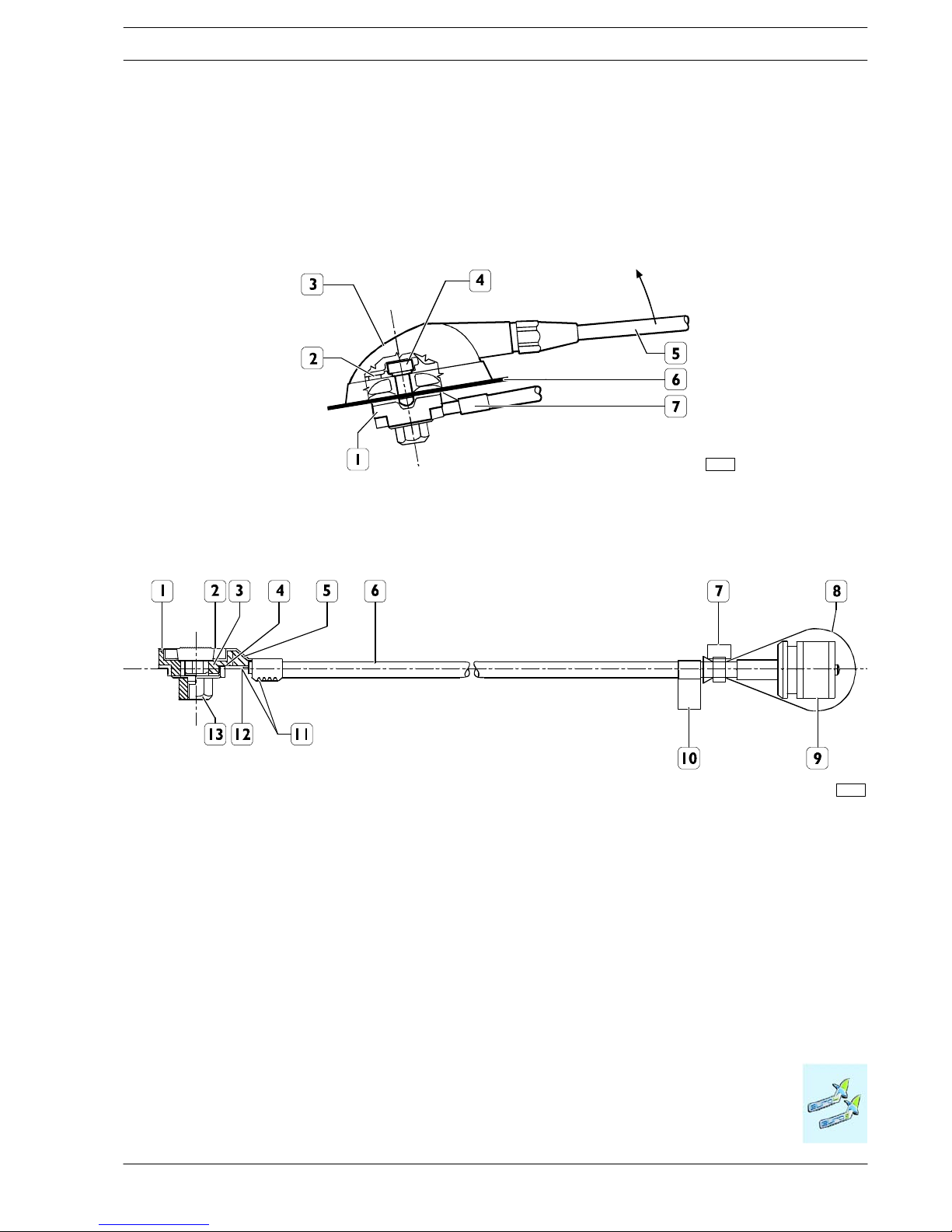
CHASSIS MODIFICATIONS
2-59
DAILY 4x4
Print 603.93.761 Base - May 2007
Electrical System: Modifications and Drawing-Off Power
- Use existing holes for routing the cable. Take all the necessary precautions for protecting the body if additional hole have to
be drilled (use anti-rust paint, sheath, etc.).
- Ensure a good connection with the vehicle earth both at the base of the antenna and at the device fixing to ensure maximum
power transfer.
Radio transmitters are typically fitted on the dashboard in the gear lever area or in the header rail above the driver (see Figure 2.33).
Figure 2.31
1. Antenna support - 2. Gasket (P/N for spares 244614) - 3. Fixed joint cover (P/N for spares 217522) - 4. Fixing screw
M6x8.5 (torque to 2 Nm) - 5. Antenna (spare P/N for complete rod 675120) - 6. Roof - 7. Antenna extension lead
98915
Figure 2.32
1. Antenna connector - 2. Ground wire - 3. Insulator - 4. Signal wire - 5. Capacitor (100pF) - 6. Cable RG 58 (characteristic
impedance = 50 Ω) - 7. Clamp - 8. Protective cap - 9. Con nector (N.C. SO - 239) transceiver side - 10. Test executed sticker
- 11. The 100pF capacitor must be soldered on th e lower pin and crimped to the ground braid - 12. The lower pin must be
soldered to the core conductor of the cable - 13. Nut
99349
Page 84
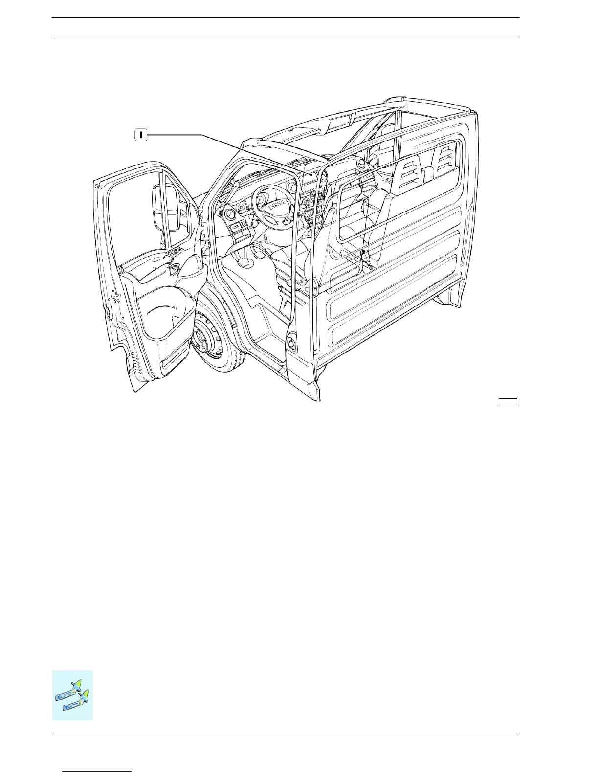
2-60
CHASSIS MODIFICATIONS
D
AILY 4x4
Base - May 2007 Print 603.93.761
Electrical System: Modifications and Drawing-Off Power
Figure 2.33
1. Location of the CB transceiver unit (City Band)
119358
Two-way systems for GSM/PCS/UMTS mobile phones
Cellular telephonesystems must be installed using the power system provided in the vehicle. Connect to terminal 30 via a supple-
mentary fuse.
The devices must be legally type-approved and fixed (not portable). Install the transmitting part in a flat, dry area separate from the
electronic components of the vehicle, away from humidity and vibrations.
• The SWR must be as close as possible to one. The recommended value is 1.5, while the maximum acceptable value must not
in any case be greater than 2.
• The AERIAL GAIN values must be as high as possible and ensure sufficient spatial uniformity, normally with deviations from the
average value in the order of 1.5dB in the 870-960 MHz band and 2 dB in the 1710-1880MHz band.
• The RADIATED CAB FIELD value must be as low as possible. We suggest < 1 V/m as a qualit y target. In any case, the value
must not exceed limits imposed by current European guidelines.
• For this reason, the aerial must always be placed on the outside of the vehicle cab, if possible on a broad metal base fitted as
upright as possible with the connection lead facing downwards, observing the Manufacturer’s installation instructions and warnings.
The ideal location of the antenna is on the front of the cab roof at a distance no less than 30 cm from other antennas.
Page 85

CHASSIS MODIFICATIONS
2-61
DAILY 4x4
Print 603.93.761 Base - May 2007
Electrical System: Modifications and Drawing-Off Power
Follow the precautions below when connecting and arranging the wires:
- Use a top quality cable particularly as concerned to the protective sh ielding.
- The cable route must be at a suitable distance (minimum 50 mm) from pre-existing wiring. Ensure the minimum distance from
the metallic structure of the cab. Avoid excessively pulling or pinching the cable.Installation on the left or right-hand side is preferable.
- Never shorten or extend the coaxial antenna cable.
- Use existing holes for routing the cable. Take all the necessary precautions for protecting the body if additional hole have to
be drilled (use anti-rust paint, sheath, etc.).
- Ensure a good connection with the vehicle earth both on the base of the antenna and at the device fixing to ensure maximum
power transfer.
Cellular telephones are typically fitted on the dashboard in gear lever area or in the header rail above the driver.
GPS antenna cable and navigation system installation
Correctand carefulassembly of GPS antennas in the vehicle isextremely important forcorrect operation andmaximumperform-
ance.
The antennas should if possible be fitted in a concealed position where they cannot be seen.
Arranging the GPS antenna is a delicate matter. Th e power of the signal received from the satellite is very weak (approximately
136dBm), so any obstacle can effect quality and performance of the receiver.
• The SWR must be as close as possible to one. The recommended value is 1.5, while the maximum acceptable value must not
in any case be greater than 2 i n the GPS frequency range (1575.42 +1.023 MHz).
• The AERIAL GAIN values must be as high as possible and ensure sufficient spatial uniformity, normally with deviations from the
average value in the order of 1.5dB in the 1575.42+1.023 MHz band.
The GPS an tenna must be installed in a position ensuring maximum visibility of the sky.
The minimum angle of visibility must be 90°. Sky visibility must n ot be obscured by objects or metallic structu res. The installation
position must be horizon tal.
The ideal location for the GPS antenna is under the plastic dashboard in the middle and at the base of the vehicle windscreen.
Do not install the antenna under any type of metallic structure in the cab.
Position the GPS antenna at a distance which is not less than 30 cm from another antenna.
Follow the precautions below when connecting and arranging the wires:
- use a top quality c able particularly concerning the protective shielding.
- The wire course must be at a suitable distance (minimum 50 mm) from pre-existing wiring. Ensure the minimum distance from
the metallic structure of th e cab. Avoid excessively pulling or pinching the cable. Installation on the left or right-han d side is
preferable.
- Never shorted or extend the coaxial antenna cable.
- Use existing holes for routing the cable. Take all the necessary precautions for protecting the body if additional holes have to
be drilled (use anti-rust paint, sheath, etc.).
- Ensure a good connection with the vehicle earth both on the base of the antenna and at the device fixing to ensure maximum
power transfer.
Navigation systems must be installed using the power system provided in the vehic le. Connect to terminal 30 via a supplementary
fuse.
The devices must be legally type-approved and fixed (not portable). Install the transmitting part in a flat, dry area separate from the
electronic components of the vehicle, away from humidity and vibrations.
Page 86

2-62
CHASSIS MODIFICATIONS
D
AILY 4x4
Base - May 2007 Print 603.93.761
Electrical System: Modifications and Drawing-Off Power
Installation of IVECO original radio
The radio comes in two configu ration s:
- Radio with CD player
- Radio with CD+MP3 player
The IVECO radio is built into the system on the CAN network and allows:
- Message repetition to comfort control panel
- Volume adjustment according to vehicle speed
- Integration with Convergence V2 system
- Recognition/antitheft system with body computer
If the original radio is not present, an aftermarket radio may be fitted.
119375
Radio connector
Aerial
connector
119376
119377
Page 87

CHASSIS MODIFICATIONS
2-63
DAILY 4x4
Print 603.93.761 Base - May 2007
Electrical System: Modifications and Drawing-Off Power
2.16.3 Additional equipment
Where the set power supply requires a voltage other than the system voltage, this must be obtained by means of an appropriate
DC/DC 12-24V converter/inverter unless one is already fitted. The power cables for the converter must be as short as possible
with no coils and maintaining the minimum distance from the reference plane.
!
When installing devices that could interact with other electronic systems, namely: Retarders, Extra
heaters, Power take-offs, Air conditioners, Automatic transmissions, Telematics and Speed limiters
- contact IVECO to for efficient application.
For the operations which might cause interference with the basic system, it is necessary to carry out
diagnostic checks in order to make sure that the system has been properly fitted. These tests can be
carried out using on-board diagnostic E CUs (Electronic Control Units) or IVECO service.
IVECO reserves the right to void vehicle warranty if work is carried out in a way which does not comply with IVECO directives.
NOTE
!
Using receiving-transmitting devices not approved or fitting auxiliary amplifiers may seriously affect
correct operation of the electric/electronic units fitted to the vehicle, with adverse effects on the
vehicle and/or driver safety.
!
Any damage to the system caused by the use of receiving-transmitting units not approved or the
addition of auxiliary amplifiers shall not be covered by the warranty.
The vehicles system is designed to provide the necessary power to all the standard equipment. Each piece of equipment has
its own specific protection for its own function and the appropriate dimensions of the wires.
Fitting of additional equipment must include the provision of suitable protection and must not overload the vehicle’s system.
The earth connections of the additional devices must be made with a cable of an adequate size. It should be as short as possible
and permit movement of the apparatus in relation to the chassis of the vehicle.
If batteries of a greater capacity are used, due to the demand of the added loads, it is advisable to fit optional batteries or alternators
with a greater capacity.
In any case we recommend that the increase in the capacity of the batteries should not exceed 20 to 30% of the maximum values
provided as an optional extra by IVECO so as not to damage some components of the system (e.g. Starter motor). If greater capacities are required, use additional batteries making the necessary arrangements for recharging as described below.
Page 88

2-64
CHASSIS MODIFICATIONS
D
AILY 4x4
Base - May 2007 Print 603.93.761
Electrical System: Modifications and Drawing-Off Power
Supplementary batteries
The addition of an auxiliary battery to the vehicle circuit shall provide for a separate recharging system, which shall be integrated
with the vehicle one. In this case, auxiliary batteries with the same capacity as t h e original on es (110 Ah) should be provided, to
ensure correct recharging of all the batteries.
In the event that an auxiliary battery is to be installed:
- in the passenger compartment, the following batteries can be used:
a) recombination batteries (AGM or gel)
b) traditional batteries.
In both cases, the battery must be completely separated from the occupants in the vehicle. A suitable air tight container could be
used in case of:
- vapour escape (e.g. in case of alternator voltage regulator failure);
- battery explosion;
- electrolyte leaks, even in case of vehicle overturning.
In the event that type ”A” batteries are used:
- a vent to the passenger compartment exterior shall be provided.
In the event that type ”B” batteries are installed, the batteries shall be equipped with:
- a cover with a system for blowing the gas off to t h e outside, fitted with tube for conveying the acid spray to the outside;
- a flame anti-return system by means of a porous pellet (flame arrester).
Moreover, gas escape shall take place far from points liable to spark ignition as well as mechan ic/electric/electronic members and
parts. The exhaust shall be positioned in such a way that vacuum shall not be generated inside the battery.
!
Ground connection of the added battery shall be made by using a cable of adequate section, as short
as possible.
Figure 2.34
NOTE. THE DIAGRAM IS SHOWN FOR ILLUSTRATIVE PURPOSES ONLY
8888
102439
1. Standard battery - 2. Auxiliary battery - 3. Alternator with built-in regulator - 4. Starting motor - 5. Ignition key -
6. Remote-control switches - 6B. Proper remote-control switch dimensioning based on only the loads powered by the
auxiliary battery (2) - 7. No battery recharge warning light
!
All the lines downstream all the batteries shall be adequately protected, under any possible fault
condition. Failure to ensure adequate protection may pose a fire hazard and a danger to the persons.
Page 89

CHASSIS MODIFICATIONS
2-65
DAILY 4x4
Print 603.93.761 Base - May 2007
Electrical System: Modifications and Drawing-Off Power
Auxiliary alternators
The vehicle’s electric system has been designed to supply the necessary power to the installed pieces of equipment. Both the
specific protection and correct cable dimensioning are ensured for all the pieces of equipment, within the context of their own
functions.
The addition of auxiliary pieces of equipment shall provide for suitable protections and shall not overload the vehicle system.
In the event that an extra battery has to be used in parallel to the standard one, it is recommended that a heavy duty alternator
is used or an auxiliary alternator is fitted.
The auxiliary alternator shall be of the type equipped with Zener-diode rectifiers, to avoid possible damage to the installed
electric/electronic pieces of equipment owing to accidental battery disconnection. Moreover, every single alternator shall feature
a warning light or LED signalling failed battery recharge.
The auxiliary alternator shall feature the same characteristics as the standard one, and the cables shall be properly dimensioned.
In the event that modifications other than the ones described in this manual need bemade to thesystem (e.g.adding severalbatteries
in parallel), the operation shall be carried ou t togeth er with the IVECO experts.
Figure 2.35
102440
114179
NOTE. THE DIAGRAM IS SHOWN FOR ILLUSTRATIVE PURPOSES ONLY
TO THE BATTERIES
TO THE BATTERIES
Page 90

2-66
CHASSIS MODIFICATIONS
D
AILY 4x4
Base - May 2007 Print 603.93.761
Electrical System: Modifications and Drawing-Off Power
2.16.4 Current drawing
Precautions:
The points where current can be drawn and the instructions to be followed are described below.
Protection fuses MUST be used and fitted next to the point where the power is taken.
The added cables shall be protectedby runningthem insidespecial sheathes or c orrugated pipes. They shall beinstalled in accordance
with the instructions given in paragraph 2.16.5.
114081
1. Body builders. node for power take-off (engine compartment, on battery) - 2. Passage of wires between cab/engine
compartment - 3. Body builders’ connector (cab interior)
Figure 2.36
CBA voltage supply (on battery)
Figure 2.37
107635
Ref. Function
Fuse
range
Sect.
1 Positive +30 for alternator motor 500 50
2 Positive for engine opening central unit ”CVM” 150 35
3 Positive +30 for CPL - Dashboard control unit secondary loads 70 10
4 Positive +30 for CPL - Dashboard control unit primary loads 50 6
5 Positive +30 for box OPT 70 10
6 Positive +30 - Wiring for body builders’ interface - -
Page 91

CHASSIS MODIFICATIONS
2-67
DAILY 4x4
Print 603.93.761 Base - May 2007
Electrical System: Modifications and Drawing-Off Power
A distribution and protection control unit ( CBA) is installed on the battery. This is fitted with a power take-off for body builders.
The body builders’ node is installed on stu d no. 6 of the CBA.
Figure 2.38
BATTERY
BATTERY
CBA
CFO
CBA
116173
Installation precautions
1) Do not lose any parts when overturning the component.
2) Fuses must not be removed from their position during installation.
3) Fit terminals on the studs and secure with nuts (M5 flanged nut, self-locking nut, etc.). Tighten the nuts to torque (4 min - 6
max Nm)
4) Then secure the CFO (Centralina Fusibile Opzionale - optional fuse unit) to the CBA control unit, taking care to fit the hole
in the strip over the stud (M8 flanged nut, self-locking nut, etc.) of the battery terminal (built into the CBA) and tighten the nut
to the required torque ( 8.8 min - 13.2 max Nm).
Page 92

2-68
CHASSIS MODIFICATIONS
D
AILY 4x4
Base - May 2007 Print 603.93.761
Electrical System: Modifications and Drawing-Off Power
Fuse and relay box under the dashboard
It is located in a special compartment, whic h can be closed by means of a snap-in drawer.
Figure 2.39
114180
Only fuses of the prescribed type and rated current values shall be used - Danger of fire.
The fuses shall be replaced only after the cause of their actuation is eliminated. Cables shall be checked for integrity.
Table 2.18
Fuse Utilization Rated capacity
F-12 Right low-beam headlight 7.5 A
F-13 Left low-beam headlight - headlamp trim corrector 7.5 A
F-31 Relay T08-T17in CVM and BC 3A
F-32 Not used 15 A
F-33 Air heater/cigar lighter 15 A
F-34 Current draw 20 A
F-35 STANLEY solenoid 10 A
F-36 Central locking 20 A
F-37 Switch for brake lights and miscellaneous loads under 15 5A
F-38 BC-ceiling light internal relay power supply 10 A
F-39 Car radio - tachograph 15 A
F-40 Not used 10 A
F-41 Not used 10 A
F-42 Reversing light switch 5A
F-43 Windscreen wiper 20 A
F-44 Spare F-45 DDC and CDDC 3A
F-46 Spare F-47 Driver window regulator 25 A
F-48 Passenger window regulator 25 A
F-49 Air conditioner/car radio/heated seat ECU 15 A
F-50 Not used 5A
F-51 Tac hograph 5A
F-52 Spare F-53 Main vehicle panel - rear fog light 7.5 A
Table 2.19
Relay Utilization Rated output
T01 Right and left low-beam headlights 7.5 A
T11 Not used 7.5 A
T12 Cigar lighter/heater takeoff or air conditioner 3A
T13 Power discharge from the key 15 A
Page 93

CHASSIS MODIFICATIONS
2-69
DAILY 4x4
Print 603.93.761 Base - May 2007
Electrical System: Modifications and Drawing-Off Power
Fuse and relay box in the engine compartment (CVM)
Figure 2.40
T27 T26 T25
114179
Table 2.20
Fuse Utilization Rated capacity
F-0 Ignition spark plugs 60 A
F-1 Not used 40 A
F-2 Not used 30 A
F-3 Not used 30 A
F-4 Siren 30 A
F-5 Ignition switch 30 A
F-6 Fan electromagnetic coupling (Baruffaldi) 20 A
F-7 Side lights 20 A
F-8 Heater or air conditioner fans 30 A
F-9 Windscreen washer 20 A
F-10 Warning horn 7.5 A
F-11 EDC 16 (secondary loads) 10 A
F-14 Right h igh-beam headlight 7.5 A
F-15 Left high-beam headlight 7.5 A
F-16 EDC 16, T02, T14 auxiliary heater 5A
F-17 EDC 16 (primary loads) 15 A
F-18 Not used 10 A
F-19 Fan electromagnetic coupling (Baruffaldi) 5A
F-20 Fuel filter heater 25 A
F-21 Fuel pump 15 A
F-22 EDC 16 (primary loads) 25 A
F-23 Auxiliary h eater 10 A
F-24 PTO 15 A
F-30 Left and right fog light 15 A
Page 94

2-70
CHASSIS MODIFICATIONS
D
AILY 4x4
Base - May 2007 Print 603.93.761
Electrical System: Modifications and Drawing-Off Power
Table 2.21
Relay Utilization Rated output
T02 Right and left high-beam headlights 20 A
T03 Warning horn 20 A
T05 Fan electromagnetic cou pling power supply (Baruffaldi) 20 A
T06 Fan electromagnetic cou pling power supply (Baruffaldi) 20 A
T07 Side lights 50 A
T08 Heater or air conditioner fans 20 A
T09 EDC 16 (main relay) 30 A
T10 Fuel pump 20 A
T14 Left and right fog lights 20 A
T17 Windscreen washer 20 A
T19 Fuel filter heater 20 A
T20 MODUS or E.A.SY. diagnosis 20 A
Table 2.22
Not incl. in
control unit
Utilization Rated output
T25 Windscreen wiper switch-on/switch-off 10/20 A
T26 Windscreen wiper speed 1 & 2 10/20 A
T27 Mirror/windscreen power supply 20 A
Page 95

CHASSIS MODIFICATIONS
2-71
DAILY 4x4
Print 603.93.761 Base - May 2007
Electrical System: Modifications and Drawing-Off Power
Optional fuse box (engine compartment)
Figure 2.41
114080
Table 2.23
Relay Drawing ref. Utilization Rated output
T04 1 Rotary lights 20 A
T16 12 Working lights 10 A
T15 3 Free T22 4 Air conditioning compressor actuation 20 A
T18 6 Baruffali cut-out 20 A
T24 7 Power takeoff actuation enable 20 A
T23 9 Air conditioning compressor 20 A
T21 10 Compressor ON signal fro EDC 16 20 A
Table 2.24
Not incl. in
control unit
Drawing ref. Utilization Rated output
F-55 2 Rotary lights 10 A
F-25 5 Trailer connector 10 A
F-28 8 APU power supply 15 A
F-27 11 Working lights 10 A
Page 96

2-72
CHASSIS MODIFICATIONS
D
AILY 4x4
Base - May 2007 Print 603.93.761
Electrical System: Modifications and Drawing-Off Power
Body builders’ connectors (cab interior)
The new Daily is fitted with two connectors to be used by body builders to interface with the vehicle electrical system.
119356
Figure 2.42
The connectorsare located behind
the passenger side compartment
in an easily accessible area.
Passing cables from inside the cab to outside
Electric cables may be passed from outside the cab to the engine compartment through five 10 mm diameter holes stamped
in the bulkhead coupling near the brake servo. Seal the cable rou ting point
to prevent fumes passing from the engine compartment
to the c abin.
Figure 2.43
119355
!
Any damage caused by failure to comply with procedure is not covered by the warranty.
Page 97

CHASSIS MODIFICATIONS
2-73
DAILY 4x4
Print 603.93.761 Base - May 2007
Electrical System: Modifications and Drawing-Off Power
Maxifuse and megafuse fuses
Fuse holder are available at the IVECO shops, to protect high-absorption c urrent drawing.
They shall be positioned (as near the battery drawing terminal as possible) by t he body builder depending on the space available
on the vehicle.
Figure 2.44
119357
Capacity IVECO ref.
no.
Cable section Capacity IVECO ref.
no.
Cable section
KIT 40A 4104 0110 KZ 10 mm
2
KIT 100A 4104 0112 KZ 25 mm
2
KIT 60A 4104 0111 KZ 10 mm
2
KIT 125A 4104 0113 KZ 35 mm
2
KIT 150A 4104 0114 KZ 50 mm
2
It should be pointed out that the current intensity shall, when grouping several cables, be reduced compared with the rated value
of one single cable in order to compensate for smaller heat dispersion.
As regards the vehicles the engines of which are frequently started, in the presence of current drawing and short engine rotation
time (e.g. vehicles equipped with refrigerating bodies), the battery shall be recharged at regular intervals in order to ensure efficiency
of the same.
The connections with plugs and terminals shall be of the protected, weather-proof type. Components of the same type as the one
originally fitted to the vehicle sh all be used.
In the event that units and assemblies (various components, etc.) need be relocated due to special body building or vehicle
conversion, such relocation shall be permitted providing:
In the event that a component has be installed just next to the route of a cable belonging to the original system, or a cable route
needs be changed, the same can be relocated provided that its integrity is maintained (cuts shall not be made).
Figure 2.45
!
Any damage caused by the failure to comply with the procedure shall not be covered by the warranty.
The airbag system components must not be displaced or tampered with for any reason whatsoever.
Page 98

2-74
CHASSIS MODIFICATIONS
D
AILY 4x4
Base - May 2007 Print 603.93.761
Electrical System: Modifications and Drawing-Off Power
2.16.5 Additional Circuits
These must be separated and protected by a fuse from the vehicle’s main circuit.
The cables utilised must be of a size that is suitable for the relative functions and must be well insulated. They must also be suitable
protected in sheaths (not PVC) or routed though flexible conduits in the case of a plurality of func tion s (we recommended the use
of polyamide type 6 plastic for flexible conduits) and they must be correctly installed in a place where they are protected from impact
and heat sources. Take care to avoid any chaffing with other components, particularly with live edges of the bodywork. The transit
of these cables through structural components (cross members, profiles,etc.) must be executed using suitable cable glands or protections; firstly the cables must be secured separately with insulated cable clamps (e.g. made of nylon) at adequate intervals (approx.
200 mm).
In the case of external panels use a suitable sealant on both the cable and on the panel, to avoid the risk of infiltration of water,
dust, or fumes.
Establish suitable distance between electrical wiring harnesses and other components as follows:
- 10mmfromstaticcomponents;
- 50 mm from moving components (minimum distance = 20 mm);
- 150 mm from components that generate heat (e.g. engine exhaust).
Wherever possible it is good practice to follow a different cable route for signal cables interfering at high absorbed intensity (e.g.
electric motors, solenoid valves) an d signals that are susceptible to low absorbed intensities such as sensors, maintaining in any event
a position as close as possible to the metal structu re of the vehicle in both cases.
Plug and terminal connections must be protected, resistant to weathering, and executed using components of the same type as
those utilised origin ally on the vehicle.
Use cables and fuses with the characteristics shown in the following table in accordance with th e current draw:
Table 2.25
Max. continuous current1)(A) Cable cross-section (mm2) Fuse capacity2)(A)
0 ÷ 4 0.5 5
4 ÷ 8 1 10
8 ÷ 16 2.5 20
16 ÷ 25 4 30
25 ÷ 33 6 40
33 ÷ 40 10 50
40 ÷ 60 16 70
60 ÷ 80 25 100
80 ÷ 100 35 125
100 ÷ 140 50 150
1)
Forusesofmorethan30seconds.
2)
Dependingon the position and hence the temperaturethat maybe reached in the housing, choose fuses thatcan be loaded to up to 70% - 80% of their maximum
capacity.
!
The fuse must be connected as close as possible to the current take-off point.
Precautions
- Incorrect installation of electrical accessories may affect occupant safety and cause severe damage to the vehicle.Contact IVECO
if you have any questions.
- Avoid coupling with signal transmission cables (e.g. ABS), for which a preferential path has been defined for electromagnetic
requirements (EMI).
It should be noted that when grouping several cables together, in order to compensate for the lower heat dispersal capacity
current intensity must be reduced with respect to the nominal value of a single cable.
- In vehicles subject to frequent engine starts, in the presence of power draws with limited engine running times (e.g. vehicles with
refrigerated bodies) periodic battery charges are required to maintain optimal efficiency.
Page 99

CHASSIS MODIFICATIONS
2-75
DAILY 4x4
Print 603.93.761 Base - May 2007
Electrical System: Modifications and Drawing-Off Power
2.16.6 Operations to adjust overhang
If the length of the wires on the chassis are modified to accommodate the new overhang, a watertight joint must be used with
the same specifications as those used on the standard vehicle. Components used - such as wires, connectors, terminals, ducts etc.
- must be the same type as those used originally and must be fitted correctly.
As far as electronic control device function is concerned, no joins are permitted: the cable must be rep laced by a new cable with
the same specifications as that used on the vehicle, and of appropriate length.
2.16.7 Provision for trailer
If the tail-lights are repeated on the trailer, fit the vehicle with a 13-pin trailer point.
It is no t permitted to connec t directly to the original equipment tail-light lights. Connection to the original vehicle tail-lights could
cause c urrent overloads that will be indicated by the on-board computer as operating faults.
If it is necessary to make changes to the system other than those described in this manual (e.g. inclusion of LED lights), the operation
must be carried out in conjunction with Iveco.
a) Trailer connector added by the body builder
If the vehicle is not ordered with a trailer point, a set may be ordered from parts. This consists of:
- electronic control unit;
- control unit fastening brackets;
- front bridle for connecting the control unit with the bonnet cable and chassis cable sectioning;
- chassis cable with 13-pole connector.
Installation
To ensure correct installation, the following instructions shall be followed:
- fit the electronic control unit onto the bracket next to the radiator, as illustrated in the pictures.
Figure 2.46
114195
114196
1
2
1
FRONT VIEW
1. Electronic control unit - 2. Radiator
REAR VIEW
1. Interfacing connectors
Page 100

2-76
CHASSIS MODIFICATIONS
D
AILY 4x4
Base - May 2007 Print 603.93.761
Electrical System: Modifications and Drawing-Off Power
- Disconnect the grey connector between the chassis cable and the cab cable. Connect the interfacing bridle between the
electronic control unit and the connections available on the vehicle, as illustrated in the diagram.
Figure 2.47
1. Electronic control unit with bracket - 2. Red taping (connect to the added 13-pole chassis cable) - 3. Yellow taping
(connect to the cab/bonnet cable) - 4. Connect to the chassis cable found on the vehicle - 5. Connect to the chassis ground
114197
Figure 2.48
1. To be connected to the chassis cable (from where the reversing gear sensor connection had come off) - 2. To be
connected to the reversing gear sensor - 3. Connect to the chassis ground - 4. To be connected to the control unit
connector - 5. Cable to be fitted onto the chassis
114198
For more details on connec tions and assembling, ask IVECO for the wiring diagrams.
!
Any damage to the lighting system caused by the failure to comply with the above procedure shall not
be covered by the warranty.
 Loading...