

Iveco CURSOR EURO 4 Repair Manual

CURSOR
EURO 4 ENGINES
Vehicle application
C78
C78 ENT C
C10
C10 ENT C
C13
C13 ENT C
Technical and Repair manual

This publication describes the characteristics, data and correct
methods for repair operations on each component of the vehicle.
If the instructions provided are followed and the specified
equipment is used, correct repair operations in the programmed time will be ensured, safeguarding against possible
accidents.
Before starting to perform whatever type of repair, ensure that
all accident prevention equipment is available and efficient.
All protections specified by safety regulations, i.e.: goggles,
helmet, gloves, boot, etc. must be checked and worn.
All machining, lifting and conveying equipment should be inspected before use.
The data contained in this publication was correct at the time
of going to press but due to possible modifications made by
the Manufacturer for reasons of a technical or commercial nature or for adaptation to the legal requirements of the different countries, some changes may have occurred.
No part of this publication, including the pictures, may be reproduced in any form or by any means.
Publication edited by
Iveco Motors
Iveco SpA
PowerTrain
Mkt. Advertising & Promotion
Viale dell’Industria, 15/17
20010 Pregnana Milanese
Milano (Italy)
Print P1D32C002 E -1
st
Ed. 09.2006
Produced by:
B.U. TECHNICAL PUBLISHING
Iveco Technical Publications
Lungo Stura Lazio, 15/19
10156 Turin - Italy

CURSOR EURO 4 ENGINES
1
CURSOR EURO 4 ENGINES
F2B Cursor engines Part 1
F3A Cursor engines Part 2
F3B Cursor engines Part 3
Print P1D32C002 E Base - September 2006

2
CURSOR EURO 4 ENGINES
Base - September 2006 Print P1D32C002 E

CURSOR EURO 4 ENGINES
3
SPECIAL REMARKS
The subjects usually dealt with in each section are:
Technical data table, Driving torques, Equipment, Diagnostic, Removal and Fitting in place, Repair operations.
Where possible, the same sequence of procedures has been followed for easy reference.
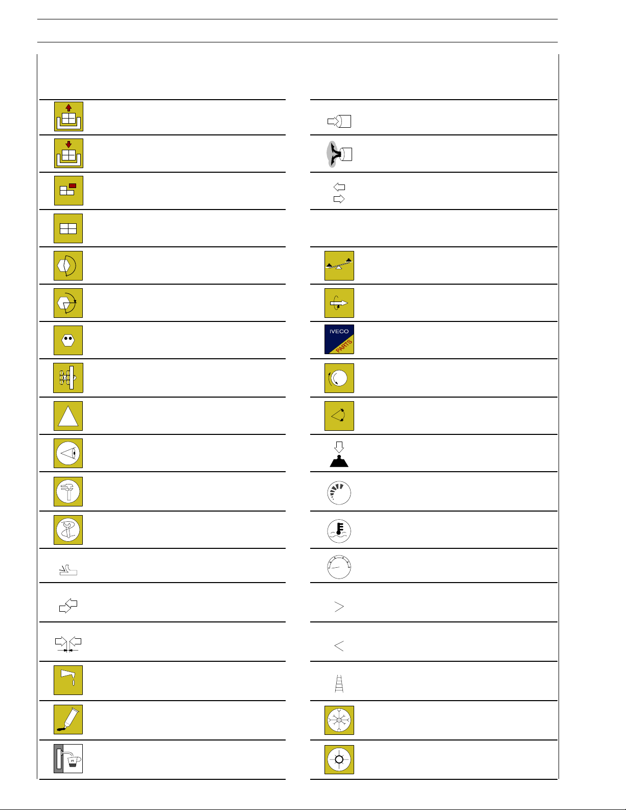
Diagrams and symbols have been widely used to give a clearer and more immediate illustration of the subject being dealt with, (see
next page) instead of giving descriptions of some operations or procedures.
Example
∅
Ø 1 = housing for connecting rod small end bush
1
Ø 2 = housing for connecting rod bearings
∅
2
Tighten to torque
Tighten to torque + angular value
α
Print P1D32C002 E Base - September 2006
4
Graph and symbols
CURSOR EURO 4 ENGINES
Removal
Disconnection
Refitting
Connection
Removal
Disassembly
Fitting in place
Assembly
Tighten to torque
Tighten to torque + angle value Rolling torque
α
Press or caulk
Regulation
Adjustment
ρ
Intake
Exhaust
Operation
Compression ratio
Tolerance
Weight difference
Replacement
Original spare parts
Rotation
!
Warning
Note
Visual inspection
Fitting position check
Measurement
Value to find
Check
Equipment Temperature
Surface for machining
Machine finish
Interference
Strained assembly
Thickness
Clearance
Lubrication
Damp
Grease
Sealant
Adhesive
Air bleeding
bar
Angle
Angular value
Preload
Number of revolutions
Pressure
Oversized
Higher than….
Maximum, peak
Undersized
Less than….
Minimum
Selection
Classes
Oversizing
Temperature < 0 °C
Cold
Winter
Temperature > 0 °C
Hot
Summer
Base - September 2006 Print P1D32C002 E

F2B CURSOR EURO 4 ENGINES
1
Part 1
F2B CURSOR EURO 4 ENGINES
Section
General specifications
Fuel 2
Vehicle application 3
General overhaul 4
Tools 5
Safety prescriptions Appendix
1
PREFACE TO USER’S GUIDELINE MANUAL
Section 1 describes the F2B engine illustrating its features
and working in general.
Section 2 describes the type of fuel feed.
Section 3 relates to the specific duty and is divided in four separate parts:
1. Mechanical part, related to the engine overhaul,
limited to those components with different characteristics
based on the relating specific duty.
2. Electrical part, concerning wiring harness, electrical
and electronic equipment with different characteristics
based on the relating specific duty.
3. Maintenance planning and specific overhaul.
4. Troubleshooting part dedicated to the operators who,
being entitled to provide technical assistance, shall have simple
and direct instructions to identify the cause of the major inconveniences.
Sections 4 and 5 illustrate the overhaul operations of the engine overhaul on stand and the necessary equipment to execute
such operations.
The appendix reports general safety prescriptions to be followed by all operators whether being in-charge of installation or
maintenance, in order to avoid serious injury.
Print P1D32C002 E Base - September 2006

2
F2B CURSOR EURO 4 ENGINES
Base - September 2006 Print P1D32C002 E

F2B CURSOR EURO 4 ENGINES
UPDATING
Section Description Page Date of revision
3
Print P1D32C002 E Base - September 2006

4
F2B CURSOR EURO 4 ENGINES
Base - September 2006 Print P1D32C002 E

F2B CURSOR EURO 4 ENGINES
SECTION 1 - GENERAL SPECIFICATIONS
SECTION 1
General specifications
CORRESPONDENCE BETWEEN TECHNICAL CODE
AND COMMERCIAL CODE 3.............
ENGINE SECTIONS 5......................
LUBRICATION 7..........................
- Oil pump 8.............................
- Overpressure valve 8.....................
- Oil pressure control valve 9................
- Heat exchanger 9........................
- By-pass valve inside the filter support/heat
exchanger assembly 10.....................
1
Page
- Thermostatic valve 10......................
- Engine oil filters 10........................
- Valve integrated in piston cooling nozzle 11.....
COOLING 12..............................
- Description 12............................
- Operation 12............................
- Water pump 13..........................
- Thermostat 13...........................
TURBOCHARGING 14......................
VGT TURBOCHARGER 14...................
- Actuator 15..............................
- Solenoid valve for VGT control 15............
DENOX SYSTEM 2 16.......................
- General remarks 16........................
- Tank 18.................................
- AdBlue fluid level gauge control 18............
Print P1D32C002 E Base - September 2006

2
SECTION 1 - GENERAL SPECIFICATIONS
- By-pass valve 18..........................
- Pump module 19.........................
- Dosing module 19........................
- Catalyst 19..............................
- Exhaust gas temperature sensor 20...........
- Humidity detecting sensor 21................
F2B CURSOR EURO 4 ENGINES
Page
Base - September 2006 Print P1D32C002 E

F2B CURSOR EURO 4 ENGINES
SECTION 1 - GENERAL SPECIFICATIONS
CORRESPONDENCE BETWEEN TECHNICAL CODE AND COMMERCIAL CODE
Technical Code Commercial Code
F2BE3681C C78 ENT C
F2BE3681B C78 ENT C
F2BE3681A C78 ENT C
3
Print P1D32C002 E Base - September 2006

4
SECTION 1 - GENERAL SPECIFICATIONS
F2B CURSOR EURO 4 ENGINES
Base - September 2006 Print P1D32C002 E
F2B CURSOR EURO 4 ENGINES
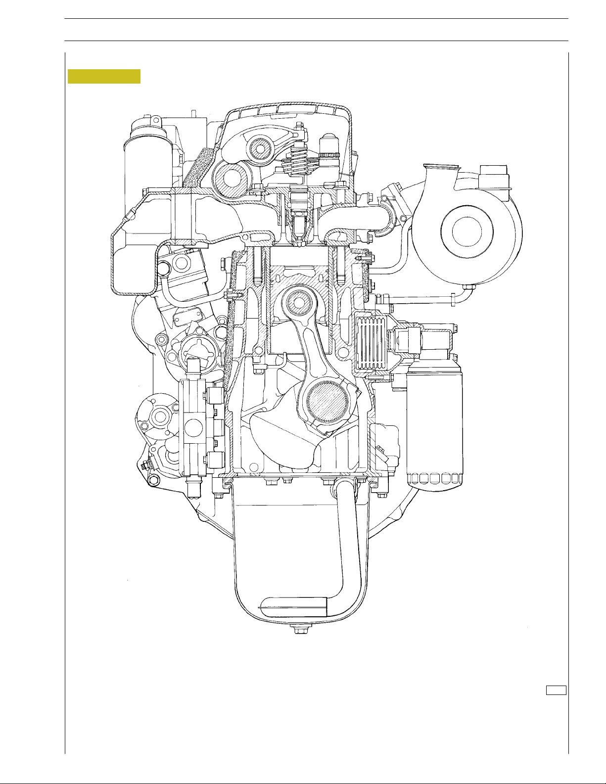
ENGINE SECTIONS
Figure 1
SECTION 1 - GENERAL SPECIFICATIONS
5
78841
ENGINE - CROSS SECTION
Print P1D32C002 E Base - September 2006
6
SECTION 1 - GENERAL SPECIFICATIONS
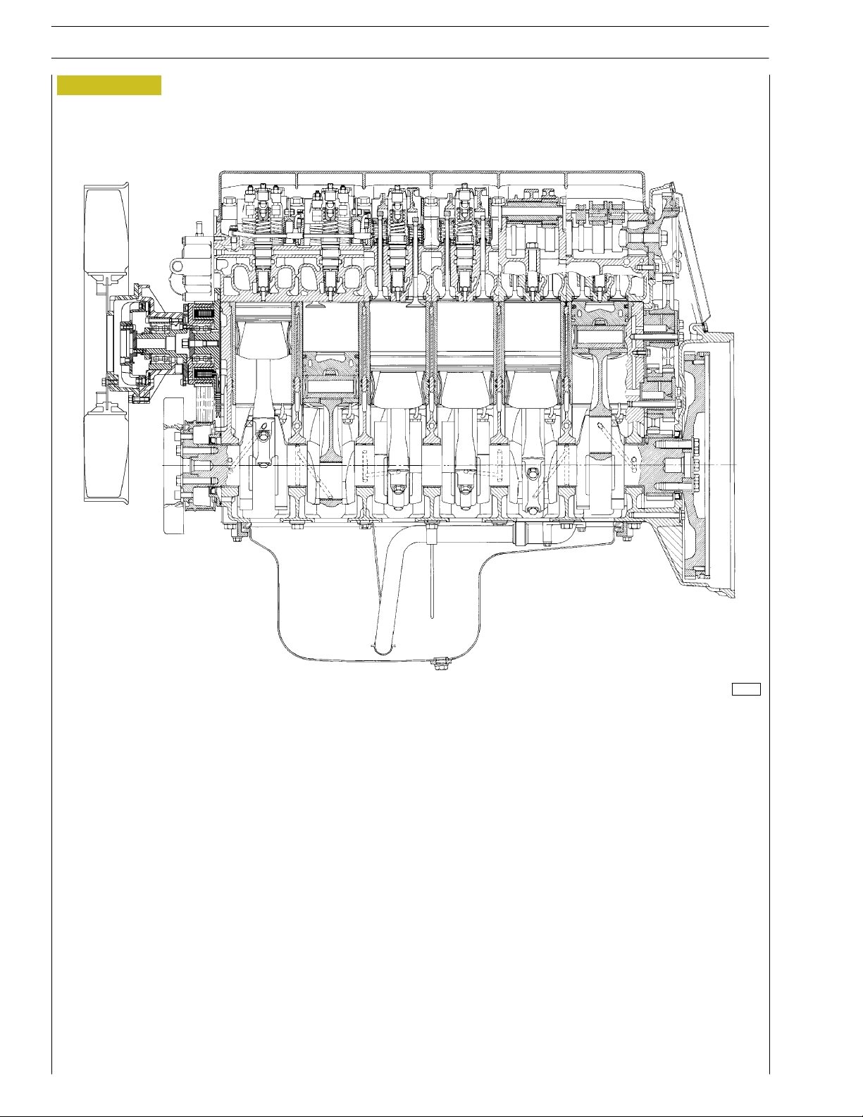
Figure 2
F2B CURSOR EURO 4 ENGINES
78839
ENGINE - LONGITUDINAL SECTION
Base - September 2006 Print P1D32C002 E
F2B CURSOR EURO 4 ENGINES
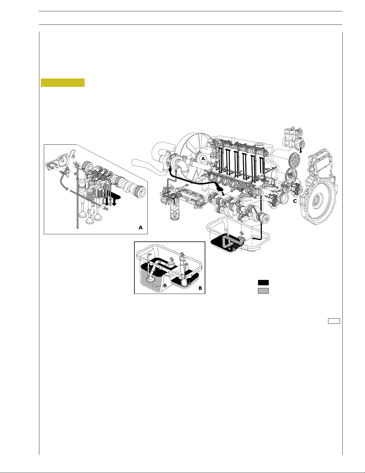
LUBRICATION
Engine lubrication is obtained with a gear pump driven by the crankshaft via gears.
A heat exchanger governs the temperature of the lubricating oil.
The oil filter, signalling sensors and safety valves are installed in the intercooler.
Figure 3
SECTION 1 - GENERAL SPECIFICATIONS
7
B. Engine oil sump (auxiliary oil pump version)
C. Auxiliary oil pump
Dropping oil
Pressure oil
86930
LUBRICATION CIRCUIT
Print P1D32C002 E Base - September 2006
8
SECTION 1 - GENERAL SPECIFICATIONS
F2B CURSOR EURO 4 ENGINES
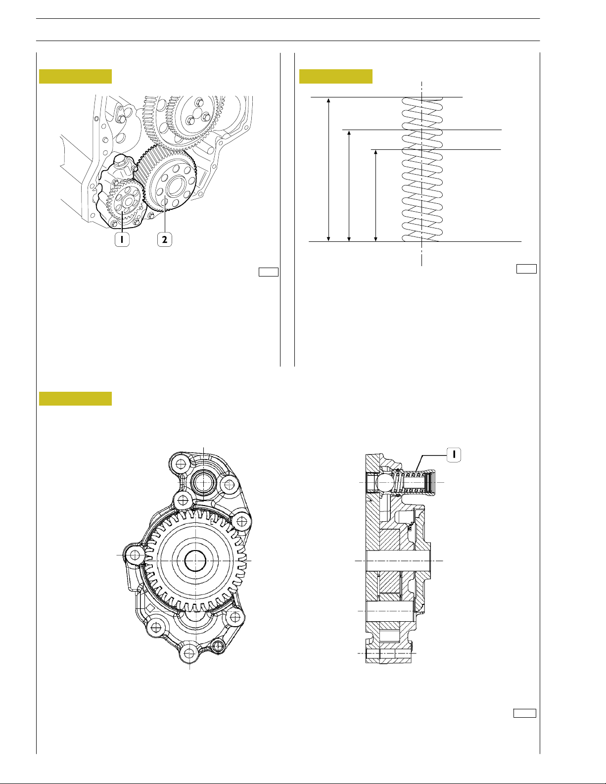
Oil pump
Figure 4
60560
The oil pump (1) cannot be overhauled. On finding any
damage, replace the oil pump assembly.
See under the relevant heading for replacing the gear (2) of
the crankshaft.
Overpressure valve
Figure 6
190 ± 6N
324 ± 9N
43,65
33,5
22,95
77820
MAIN DATA TO CHECK THE OVERPRESSURE
VALVE SPRING
Figure 5
112327
OIL PUMP CROSS-SECTION
1. Overpressure valve — Start of opening pressure 10.1 ± 0.7 bars
Base - September 2006 Print P1D32C002 E
F2B CURSOR EURO 4 ENGINES
SECTION 1 - GENERAL SPECIFICATIONS
9
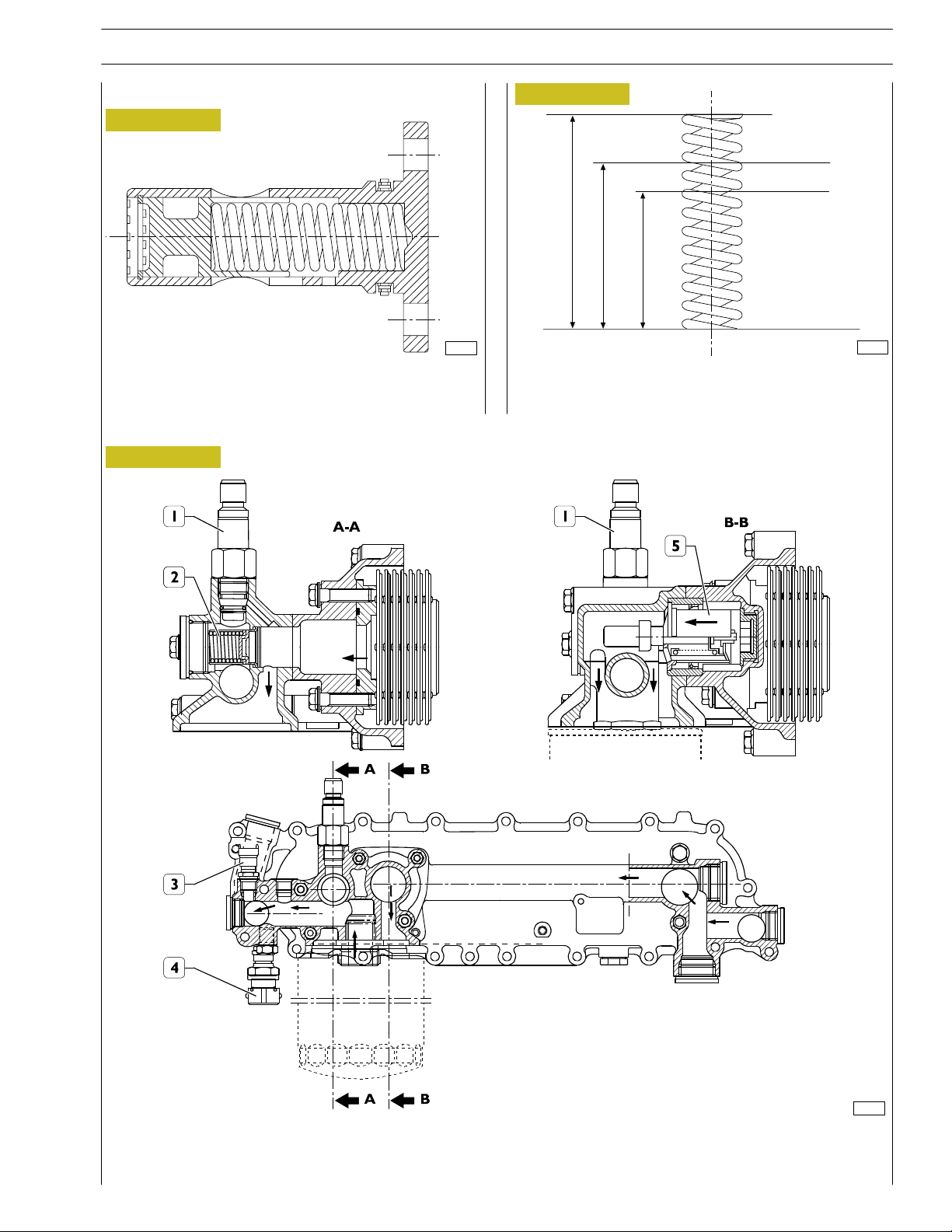
Oilpressurecontrolvalve
Figure 7
73542
The oil pressure control valve is located on the left-hand side
of the crankcase.
Start of opening pressure 5 bars.
Heat exchanger
Figure 9
Figure 8
168 ± 9
308 ± 15
63
51
36,4
88819
MAIN DATA TO CHECK THE OIL PRESSURE
CONTROL VALVE SPRING
77818
HEAT EXCHANGER
The following elements are fitted on the intercooler: 1. Transmitter for low pressure warning lamp - 2. By-pass valve - 3. Oil
temperature sensor - 4. Oil pressure sensor for single gauge - 5. Heat valve. Number of intercooler elements: 7
Print P1D32C002 E Base - September 2006
10
SECTION 1 - GENERAL SPECIFICATIONS
F2B CURSOR EURO 4 ENGINES
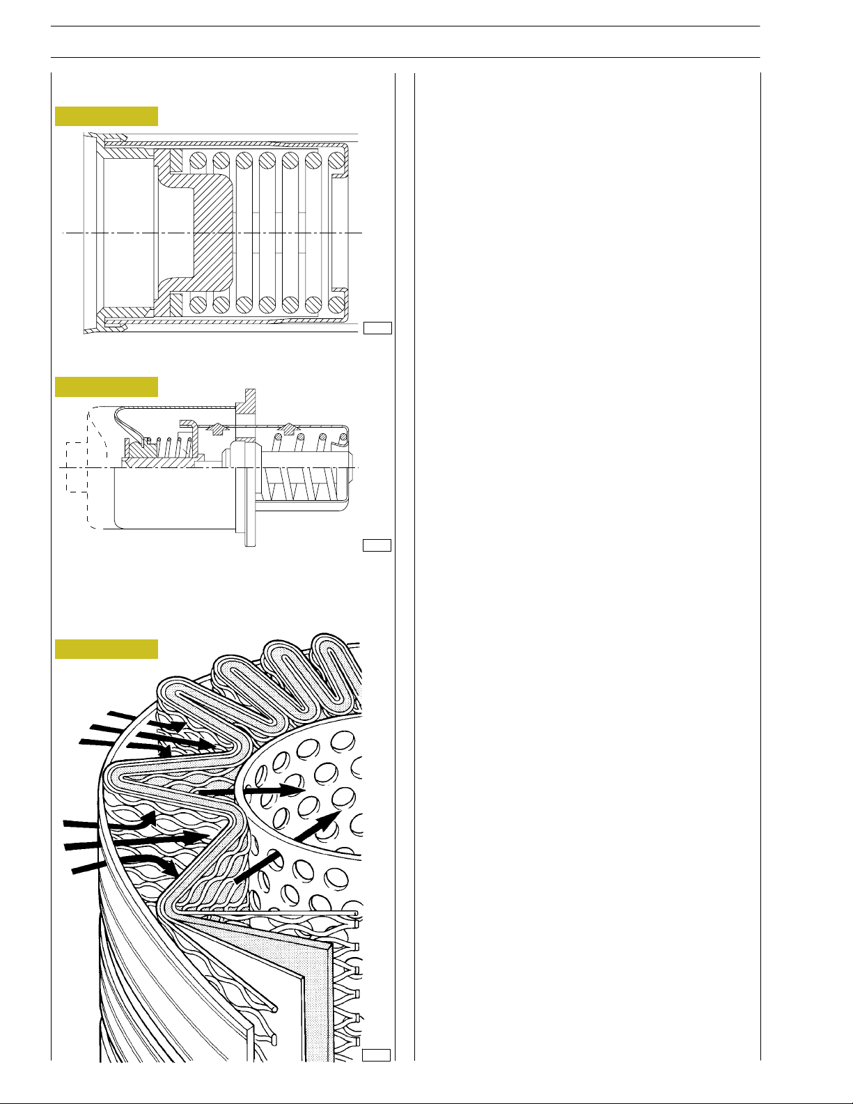
By-pass valve inside the filter support/heat exchanger assembly
Figure 10
73545
The valve quickly opens at a pressure of: 3 bars.
Thermostatic valve
Figure 11
This is a new generation of filters that permit much more
thorough filtration as they are able to holder back a greater
amount of particles of smaller dimensions than those held
back by conventional filters with a paper filtering element.
These high-filtration devices, to date used only in industrial
processes, make it possible to:
- reduce the wear of engine components over time;
- maintain the performance/specifications of the oil and
thereby lengthen the time intervals between changes.
External spiral winding
The filtering elements are closely wound by a spiral so that
each fold is firmly anchored to the spiral with respect to the
others. This produces a uniform use of the element even in the
worst conditions such as cold starting with fluids with a high
viscosity and peaks of flow. In addition, it ensures uniform
distribution of the flow over the entire length of the filtering
element, with consequent optimization of the loss of load and
of its working life.
Mount upstream
To optimize flow distribution and the rigidity of the filtering
element, this has an exclusive mount composed of a strong mesh
made of nylon and an extremely strong synthetic material.
Start of opening:
- travel 0.1 mm at a temperature of 82 ± 2°C
End of opening:
- travel 8 mm at a temperature of 97°C
.
Engine oil filters
Figure 12
Filtering element
73546
.
Composed of inert inorganic fibres bound with an exclusive
resin to a structure with graded holes, the element is
manufactured exclusively to precise procedures and strict
quality control.
Mount downstream
A mount for the filtering element and a strong nylon mesh
make it even stronger, which is especially helpful during cold
starts and long periods of use. The performance of the filter
remains constant and reliable throughout its working life and
from one element to another, irrespective of the changes in
working conditions.
Structural parts
The o-rings equipping the filtering element ensure a perfect
seal between it and the container, eliminating by-pass risks and
keeping filter performance constant. Strong corrosion-proof
bottoms and a sturdy internal metal core complete the
structure of the filtering element.
When mounting the filters, keep to the following rules:
- Oil and fit new seals.
- Screw down the filters to bring the seals into contact with
the supporting bases.
- Tighten the filter to a torque of 35÷40 Nm.
47447
Base - September 2006 Print P1D32C002 E
F2B CURSOR EURO 4 ENGINES
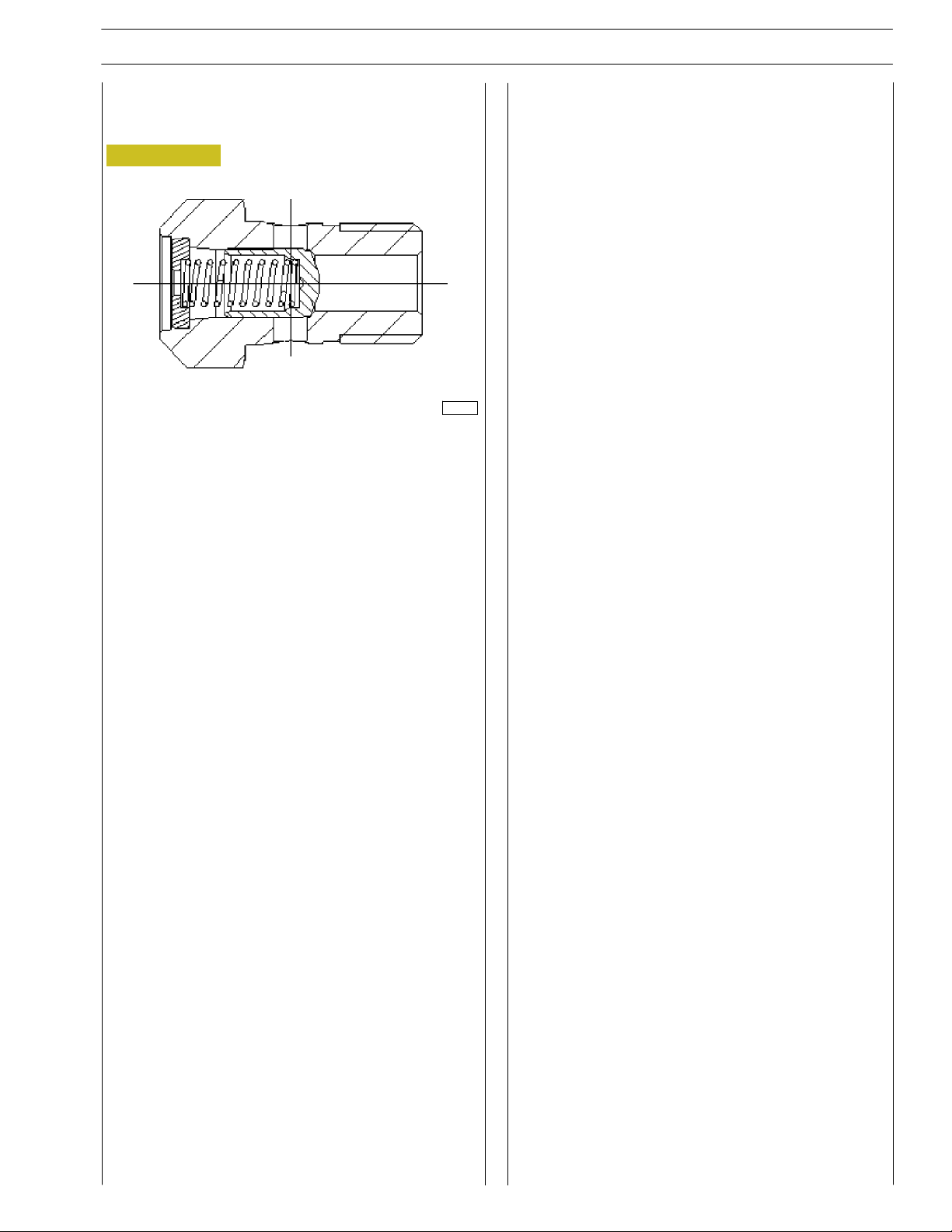
Valve integrated in piston cooling nozzle
Figure 13
109080
The valve allows oil to enter only above the threshold pressure
of 1.7 ± 0.2 bar. This permits filling the circuit and therefore
lubricating the most stressed parts even when working at
lower pressures.
SECTION 1 - GENERAL SPECIFICATIONS
11
Print P1D32C002 E Base - September 2006
12
SECTION 1 - GENERAL SPECIFICATIONS
F2B CURSOR EURO 4 ENGINES
COOLING
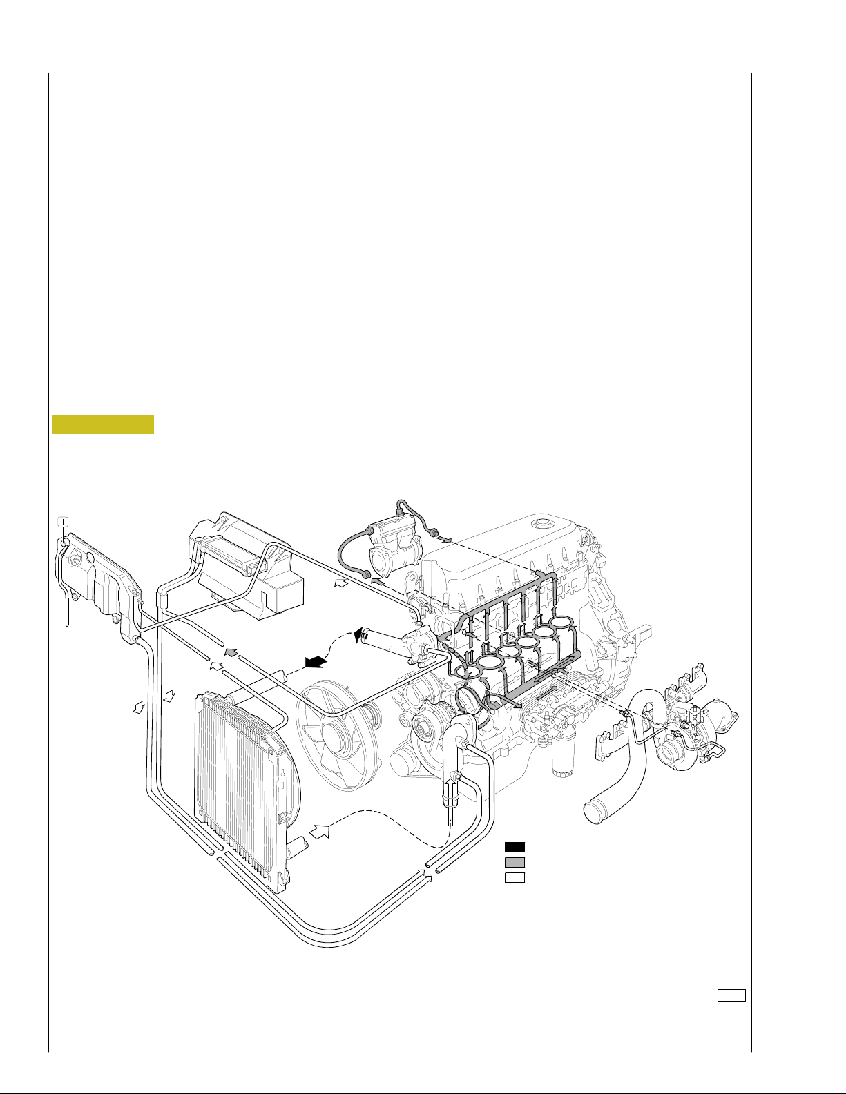
Description
The engine cooling system is of the closed-circuit, forced circulation type.
It consists mainly of the following components:
- expansion tank, not supplied (by IVECO);
- a heat exchanger to cool down lubrication oil;
- a water pump with centrifugal system incorporated in the cylinder block;
- fan, not supplied;
- a 2-way thermostat controlling the coolant circulation.
Operation
The water pump is actuated by the crankshaft through a poli-V belt and sends coolant to the cylinder block, especially to the cylinder
head (bigger quantity). When the coolant temperature reaches and overcomes the operating temperature, the thermostat is
opened and from here the coolant flows into the radiator and is cooled down by the fan.
The pressure inside the system, due to temperature change, is adequately controlled through the expansion vessel.
Figure 14
Water leaving the thermostat
Water circulating in the engine
Water entering the pump
92824
Base - September 2006 Print P1D32C002 E
F2B CURSOR EURO 4 ENGINES
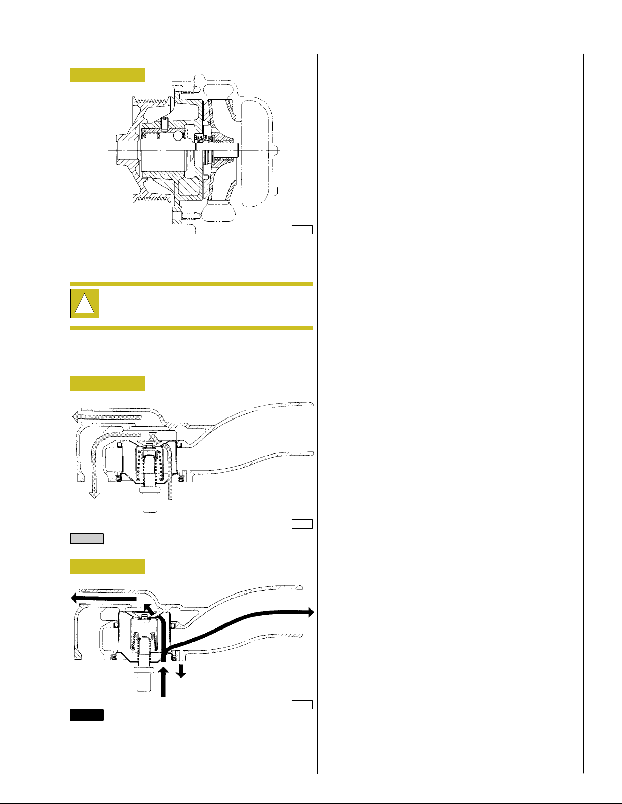
Water pump
Figure 15
44915
WATER PUMP SECTION
The water pump consists of: rotor, seal bearing and control
pulley.
Make sure that the pump casing has no cracking or
water leakage; otherwise, replace the entire pump.
!
SECTION 1 - GENERAL SPECIFICATIONS
13
Thermostat
THERMOSTAT OPERATION VIEW
Figure 16
TO THE HEATER
TO BY-PASS FROM THE HEAD
Water circulating in the engine
Figure 17
TO THE HEATER
45357
TO RADIATOR
TO EXPANSION TANK
FROM THE HEAD
45358
Water issuing from thermostat
Check thermostat operation, in case of doubts, replace it.
Start of stroke temperature 84 _C ± 2 _C
Minimum stroke 15 mm at 94 _C ± 2 _C
Print P1D32C002 E Base - September 2006
14
SECTION 1 - GENERAL SPECIFICATIONS
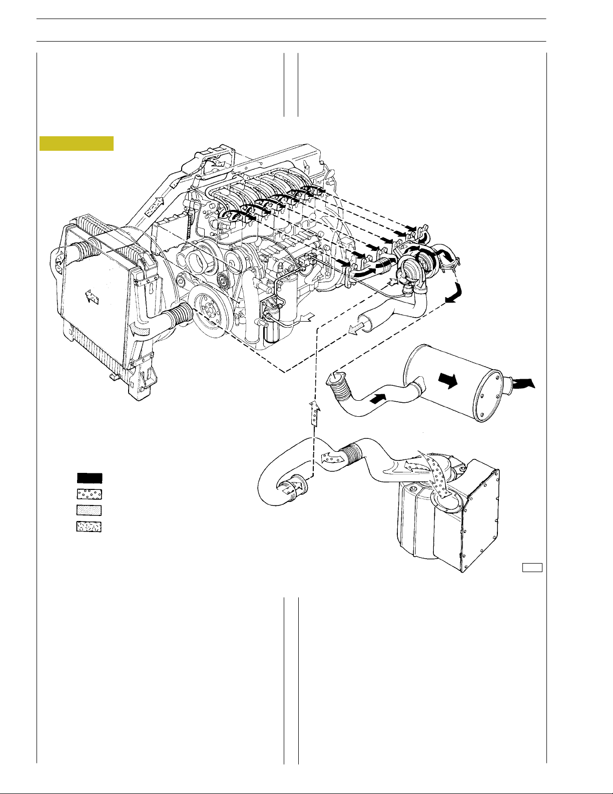
TURBOCHARGING
The turbocharging system consists of:
- air filter;
- a variable geometry or a fixed geometry turbocharger;
- “intercooler” radiator.
Figure 18
F2B CURSOR EURO 4 ENGINES
Engine exhaust gas
Intake air
Compressed air (hot)
Compressed air (cooled)
DIAGRAM OF SUPERCHARGING WITH THE VGT TURBOCHARGER
VGT TURBOCHARGER
Operating principle
The variable geometry turbocharger (VGT) consists of a
centrifugal compressor and a turbine, equipped with a mobile
device which adjusts the speed by changing the area of the
passing section of exhaust gases to the turbine.
Thanks to this solution, gas velocity and turbine speed can be
high even when the engine is idling.
If the gas is made to go through a narrow passage, in fact, it
flows faster, so that the turbine rotates more quickly.
44916
The movement of the device, choking the exhaust gas flowing
section, is carried out by a mechanism, activated by a
pneumatic actuator.
This actuator is directly controlled by the electronic control
unit by a proportional solenoid valve.
The device is in maximum closing condition at idle speed.
At high engine operating speed, the electronic control system
is activated and increases the passing section, in order to allow
the in-coming gases to flow without increasing their speed.
A toroidal chamber is obtained during the casting process in
the central body for the passage of the coolant.
Base - September 2006 Print P1D32C002 E
F2B CURSOR EURO 4 ENGINES
SECTION 1 - GENERAL SPECIFICATIONS
15
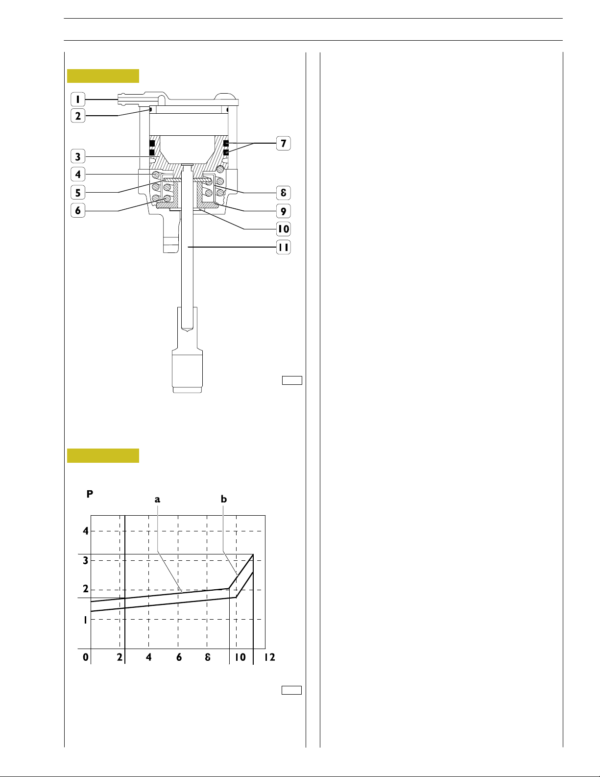
Actuator
Figure 19
Working principle (See Figure 19)
The actuator piston, connected to the drive rod, is controlled
with the compressed air introduced through the air inlet (1)
on the top of the actuator.
Modulating the air pressure varies the movement of the piston
and turbine control rod. As the piston moves, it progressively
compresses the external spring (4) until the base of the piston
reaches the disc (5) controlling the internal spring (6).
On further increasing the pressure, the piston, via the disc (5),
interferes with the bottom limit stop (10).
Using two springs makes it possible to vary the ratio between
the piston stroke and the pressure. Approximately 85% of the
stroke of the rod is opposed by the external spring and 15%
by the internal one.
Solenoid valve for VGT control
This N.C. proportional solenoid valve is located on the
left-hand side of the crankcase under the turbine.
The electronic control unit, via a PWM signal, controls the
solenoid valve, governing the supply pressure of the turbine
actuator, which, on changing its position, modifies the
cross-section of the flow of exhaust gases onto the blades of
the impeller and therefore its speed.
The resistance of the coil is approx. 20-30 Ohms.
71834
1. Air inlet - 2. Gasket - 3. Piston - 4. External spring -
5. Internal spring control disc - 6. Internal spring -
7. O-ring - 8. Spring holder - 9. Limit stop - 10. Dust seal -
11. Control rod.
Figure 20
[bar]
Stroke [mm]
72421
a Gradient characterized by the effect of the external spring
(4, Figure 19).
b Gradient characterized by the effect of the external (4,
Figure 19) and internal (6) springs.
Print P1D32C002 E Base - September 2006
16
SECTION 1 - GENERAL SPECIFICATIONS
F2B CURSOR EURO 4 ENGINES
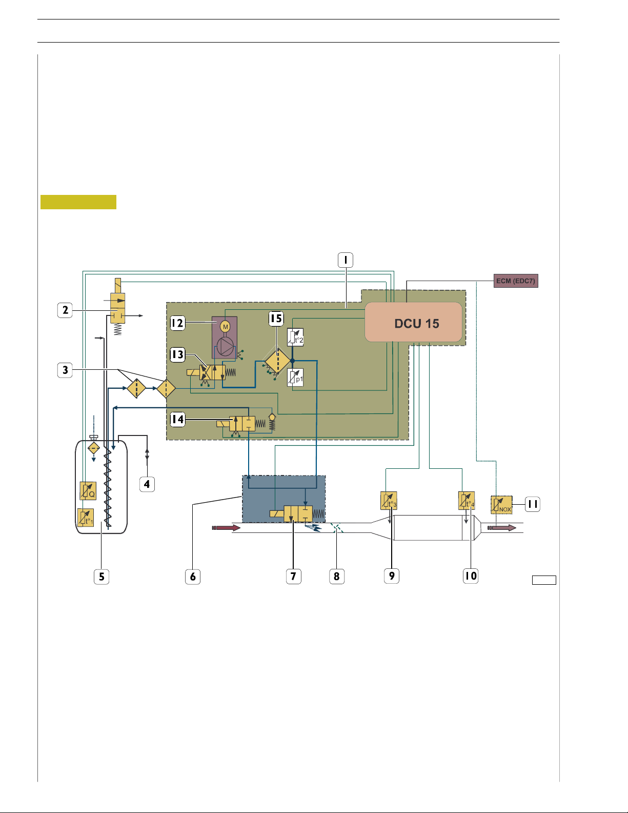
DeNOxSYSTEM 2
General remarks
In order to keep the exhaust emission values of nitric oxides (NOx) within the limits prescribed by the Euro 4 standard, with low
fuel consumption, a system for post-processing of the above substances found in exhaust gas has been fitted to the vehicles. This
system essentially consists of an electronic-control oxidizing catalyst.
The system converts, through the SCR (Selective Catalytic Reduction) process, nitric oxides (NO
nitrogen (N
)andwatervapour(H2O).
2
The SCR process is based on a series of chemical reactions, which leads, due to ammonia reacting with exhaust gas oxygen, to
a reduction of nitric oxides (NO
) found in exhaust gas.
x
Figure 21
) into inert compounds: free
x
115785
SCR SYSTEM DIAGRAM
A. PUMP MODULE - B. MEASURING OUT MODULE
1. Supply module - 2. MV4 - 3. Pre-filters - 4. Tank vent - 5. AdBlue tank with gridle - 6. Dosing module - 7. MV2 - 8. Mixer -
9. - 10. Temperature sensors - 11. Nox sensor (*) - 12. Membrane pump - 13. MV1 - 14. MV3 - 15. Main filter.
* Future application
Base - September 2006 Print P1D32C002 E
F2B CURSOR EURO 4 ENGINES
SECTION 1 - GENERAL SPECIFICATIONS
17
The system is essentially made up of:
- a tank (9) for reagent solution (water - urea: AdBlue),
equipped with level gauge (8);
- an H2O diverter valve (1);
-pumpmodule(10);
- a mixing and injection module (2);
- catalyst (4);
- two exhaust gas temperature sensors (5, 6) on catalyst
output (4);
- a moisture detection sensor (7) fitted on the engine air
intake pipe downstream from the air cleaner.
SCR system is electronically managed by DCU (Dosing Control Unit) incorporated into pump module (10); depending on
engine rpm, supplied torque, exhaust gas temperature, quantity of nitrogen oxides and humidity of air sucked in, the control unit regulates the flow rate of AdBlue solution to be let
into the system.
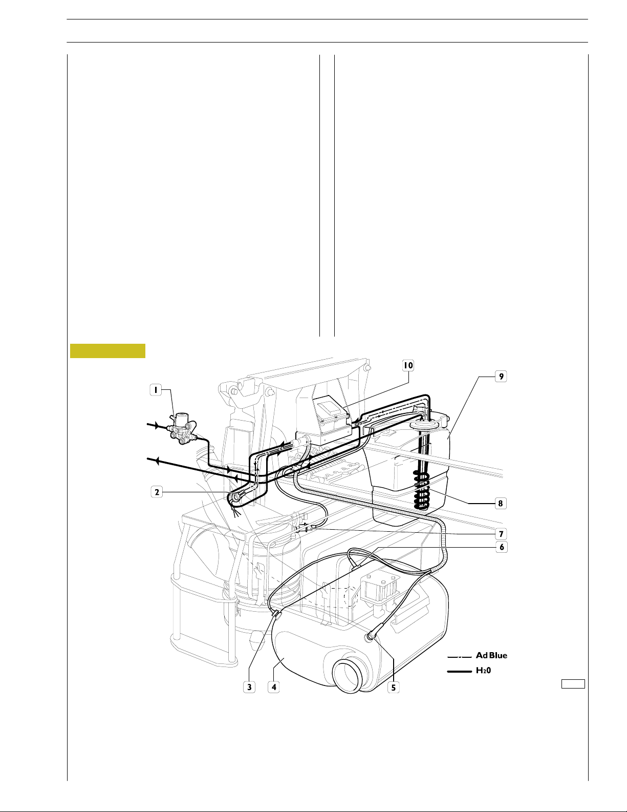
Figure 22
Pump module (10) takes reagent solution out of tank (9), then
sends it under pressure into measuring out module (2); finally,
the reagent solution is injected into the exhaust pipe upstream
of catalyst (4).
Here, the first phase of the process is realized: the reagent solution will vaporize immediately, due to the exhaust gas temperature, and will be converted into ammonia (2NH
carbon dioxide (CO
), owing to hydrolysis. At the same time,
2
)and
3
vaporization of the solution will cause a decrease in the exhaust gas temperature: the latter will get near the optimum
temperature required for the process.
Exhaust gas added with ammonia - and at the reaction temperature - will flow into catalyst where the second phase of
the process will be realized: ammonia will, by reacting with the
exhaust gas oxygen, convert into free nitrogen (N) and water
vapour (H
2
O).
108125
POSITION OF SCR SYSTEM COMPONENTS ON THE VEHICLE
1. H
O valve - 2. Dosing module - 3. Nitric oxide detecting sensor (*) - 4. Catalyst -
2
5. Outlet temperature sensor - 6. Inflow exhaust gas temperature sensor - 7. Sucked air humidity
and temperature sensor - 8. Level gauge - 9. Water-urea solution (AdBlue) tank - 10. Pump module.
* Future application
Print P1D32C002 E Base - September 2006
18
SECTION 1 - GENERAL SPECIFICATIONS
F2B CURSOR EURO 4 ENGINES
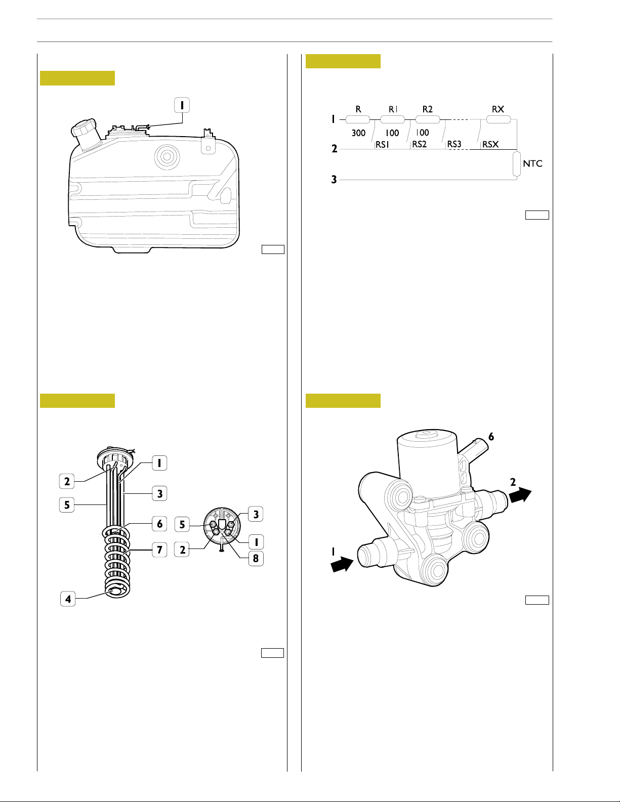
Tank
Figure 23
102295
The tank equipped with level gauge control (1) contains the
reducing substance required for the SCR process, which
consists of a 35%-urea and water solution called AdBlue.
Figure 25
102308
FUNCTIONAL WIRING DIAGRAM
The AdBlue fluid level gauge control consists of a device made
up of a set of resistors, a float, a NTC temperature sensor, and
a coil used to heat the fluid under low temperature conditions.
It informs the control unit of any current change due to the
resistor determined by the float position with respect to the
AdBlue fluid level.
AdBlue fluid l evel gauge control
Figure 24
1. AdBlue fluid suction pipe - 2. AdBlue fluid return
pipe - 3. Engine cooling hot fluid inlet pipe -
4. AdBlue (NTC) temperature sensor -
5. Engine cooling hot fluid outlet pipe - 6. Float -
7. AdBlue fluid heating coil - 8. AdBlue air vent.
116181
By-pass valve
Figure 26
108127
FUNCTIONAL WIRING DIAGRAM
1. Coolant inlet - 2. Coolant outlet -
6. Electrical connection.
The valve, which is a Normally Closed type valve, allows
AdBlue tank to be heated by engine coolant.
The NTC temperature sensor controls the by-pass valve
which closes or opens (depending on temperature) the
passage of the engine cooling hot fluid into the heating coil.
Base - September 2006 Print P1D32C002 E
F2B CURSOR EURO 4 ENGINES
SECTION 1 - GENERAL SPECIFICATIONS
19
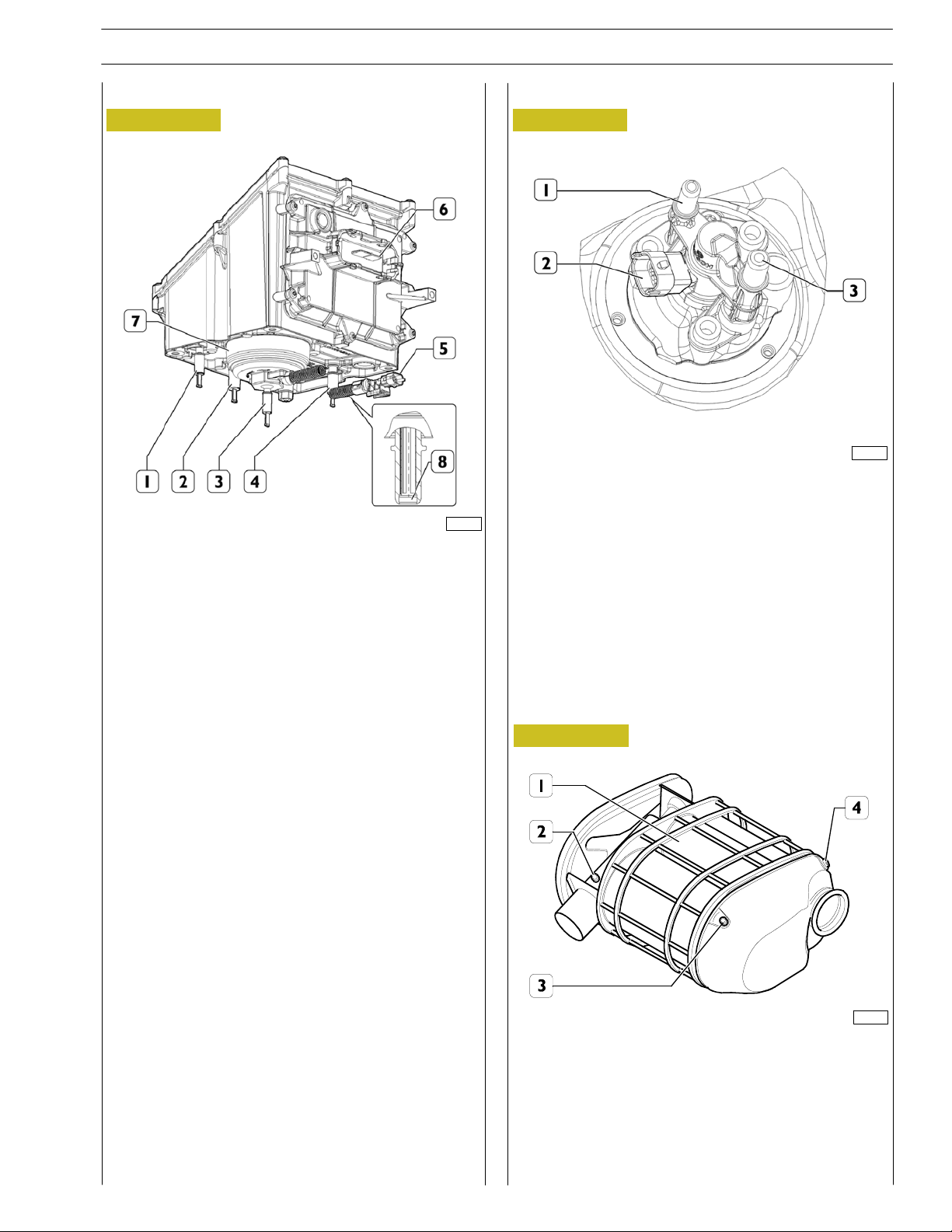
Pump module
Dosing module
Figure 27 Figure 28
108128
The function of this module is to dose the AdBlue solution to
1. AdBlue return pipe to the tank - 2. AdBlue return pipe
be conveyed to the injector.
from dosing module - 3. AdBlue solution outlet - 4. AdBlue
solution infeed - 5. Electrical connection - 6. DCU control
unit connector - 7. Filter - 8. Prefilter.
108129
1. AdBlue infeed - 2. Electrical connection -
3. AdBlue outlet.
Catalyst
Figure 29
102301
Catalyst (1), equipped with sound-proofing material, replaces
the exhaust silencer.
Inside the catalyst, the exhaust gas nitric oxides are, by reacting
with ammonia, converted into free nitrogen and water vapour.
Temperature sensors (2 & 3) and nitric oxide detecting sensor
(4) are fitted onto catalyst (1).
Print P1D32C002 E Base - September 2006

20
SECTION 1 - GENERAL SPECIFICATIONS
Exhaust gas temperature sensor
Figure 30
F2B CURSOR EURO 4 ENGINES
102303
Figure 31
102304
FUNCTIONAL WIRING DIAGRAM
1.Supplyvoltage-2.Variableoutputvoltage-3.Connector-4.Signalcable(grey)-5.Earthcable(white)-6.Sensor.
The function of this sensor is to send the control unit the catalyst inlet and outlet exhaust gas temperature values required to
calculate the amount of urea to be injected into the system.
Base - September 2006 Print P1D32C002 E
 Loading...