


International Rectifier SD303C04S20C, SD303C08S10C, SD303C08S20C, SD303C10S10C, SD303C10S15C Datasheet
...Previous Datasheet |
Index |
Next Data Sheet |
Bulletin I2066/B
SD303C..C SERIES
FAST RECOVERY DIODES
Features
High power FAST recovery diode series 1.0 to 2.0 µs recovery time
High voltage ratings up to 2500V
High current capability
Optimized turn on and turn off characteristics Low forward recovery
Fast and soft reverse recovery
Press-puk encapsulation
Case style conform to JEDEC DO-200AA Maximum junction temperature 125°C
Typical Applications
Snubber diode for GTO
High voltage free-wheeling diode
Fast recovery rectifier applications
Hockey Puk Version
350A
case style DO-200AA
Major Ratings and Characteristics
Parameters |
SD303C..C |
Units |
||
|
|
|
|
|
IF(AV) |
|
|
350 |
A |
|
|
@ Ths |
55 |
°C |
IF(RMS) |
|
|
550 |
A |
|
|
@ Ths |
25 |
°C |
|
|
|
|
|
IFSM |
|
@ 50Hz |
5770 |
A |
|
|
@ 60Hz |
6040 |
A |
|
|
|
|
|
I2t |
|
@ 50Hz |
166 |
KA2s |
|
|
|
|
|
|
|
@ 60Hz |
152 |
KA2s |
|
|
|
|
|
VRRM |
range |
400 to 2500 |
V |
|
trr |
range |
1.0 to 2.0 |
µs |
|
|
|
@ TJ |
25 |
°C |
|
|
|
|
|
TJ |
|
|
- 40 to 125 |
°C |
D-655
To Order
Previous Datasheet |
Index |
Next Data Sheet |
SD303C..C Series
ELECTRICAL SPECIFICATIONS
Voltage Ratings
|
|
Voltage |
VRRM max. repetitive |
VRSM , maximum non- |
IRRM max. |
|
Type number |
Code |
peak and off-state voltage |
repetitive peak voltage |
TJ = 125°C |
||
|
|
|
V |
V |
mA |
|
|
|
04 |
400 |
500 |
|
|
SD303C..S10C |
08 |
800 |
900 |
|
||
|
|
|
|
|
|
|
|
|
10 |
1000 |
1100 |
|
|
|
|
|
|
|
|
|
|
|
12 |
1200 |
1300 |
35 |
|
|
|
|
|
|
||
SD303C..S15C |
14 |
1400 |
1500 |
|||
|
||||||
|
|
|
|
|
|
|
|
|
16 |
1600 |
1700 |
|
|
|
|
|
|
|
|
|
SD303C..S20C |
20 |
2000 |
2100 |
|
||
|
|
|
|
|||
25 |
2500 |
2600 |
|
|||
|
|
|
||||
|
|
|
|
|
|
|
Forward Conduction
|
Parameter |
SD303C..C |
Units |
Conditions |
|
|
|
|
|
|
|
|
|
|
|
|
|
|
|
|
|
||
IF(AV) |
Max. average forward current |
350(175) |
A |
180° conduction, half sine wave. |
|
|
|
||||
|
@ Heatsink temperature |
55(75) |
°C |
Double side (single side) cooled |
|
|
|
||||
|
|
|
|
|
|||||||
IF(RMS) |
Max. RMS current |
550 |
A |
@ 25°C heatsink temperature double side cooled |
|||||||
IFSM |
Max. peak, one-cycle |
5770 |
|
t = 10ms |
|
No voltage |
|
|
|
|
|
|
non-repetitive forward current |
6040 |
A |
t = 8.3ms |
|
reapplied |
|
|
|
|
|
|
|
|
|
|
|
|
|
|
|
|
|
|
|
4850 |
t = 10ms |
|
100% VRRM |
|
|
|
|
|
|
|
|
|
|
|
|
|
|
|
|||
|
|
5080 |
|
t = 8.3ms |
|
reapplied |
|
Sinusoidal half wave, |
|||
|
|
|
|
|
|
|
|
|
|
|
|
I2t |
Maximum I2t for fusing |
166 |
|
t = 10ms |
|
No voltage |
|
Initial T |
J |
= T |
max. |
|
|
|
|
|
|
|
|
|
|
J |
|
|
|
152 |
KA2s |
t = 8.3ms |
|
reapplied |
|
|
|
|
|
|
|
|
|
|
|
|
|
|
|
|
|
|
|
117 |
t = 10ms |
|
100% VRRM |
|
|
|
|
|
|
|
|
|
|
|
|
|
|
|
|||
|
|
107 |
|
t = 8.3ms |
|
reapplied |
|
|
|
|
|
|
|
|
|
|
|
|
|
||||
I2Öt |
Maximum I2Öt for fusing |
1660 |
KA2Ös |
t = 0.1 to 10ms, no voltage reapplied |
|
||||||
VF(TO)1 Low level of threshold voltage |
1.14 |
V |
(16.7% x p x IF(AV) < I < p x IF(AV)), TJ = TJ max. |
||||||||
VF(TO)2 |
High level of threshold voltage |
1.63 |
(I > p x IF(AV)), TJ = TJ max. |
|
|
|
|
||||
|
|
|
|
|
|||||||
rf1 |
Low level of forward slope resistance |
1.14 |
mW |
(16.7% x p x IF(AV) < I < p x IF(AV)), TJ = TJ max. |
|||||||
rf2 |
High level of forward slope resistance |
0.77 |
(I > p x IF(AV)), TJ = TJ max. |
|
|
|
|
||||
|
|
|
|
|
|||||||
VFM |
Max. forward voltage |
2.26 |
V |
Ipk= 1100A, TJ = 25°C, tp = 10ms sinusoidal wave |
|||||||
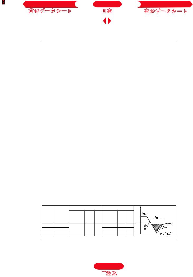
Recovery Characteristics
Code |
TJ = 25 |
o |
C |
Test conditions |
|
Max. values @ TJ= 125°C |
|||
|
|
|
|
|
|
|
|||
|
typical trr |
Ipk |
di/dt |
Vr |
trr |
Qrr |
Irr |
||
|
@ 25% IRRM |
Square Pulse |
|
|
@ 25% IRRM |
|
|
||
|
(ms) |
|
|
(A) |
(A/ms) |
(V) |
(ms) |
(mC) |
(A) |
S10 |
1.0 |
|
|
|
|
|
2.4 |
52 |
33 |
S15 |
1.5 |
|
|
750 |
25 |
-30 |
2.9 |
90 |
44 |
S20 |
2.0 |
|
|
|
|
|
3.2 |
107 |
46 |
|
|
|
|
|
|
|
D-656 |
|
|
To Order

Previous Datasheet |
Index |
Next Data Sheet |
SD303C..C Series |
Fig. 3 - Current Ratings Characteristics |
|
|
Fig. 4 - Current Ratings Characteristics |
||||||||||||||||||||||||||||||||||||||||||||
|
|
|
|
|
|
|
|
|
|
|
|
|
|
|
|
|
|
|
|
|
|
|
|
|
|
|
|
|
|
|
|
|
|
|
|
|
|
|
|
|
|
|
|
|
|
|
|
|
|
|
|
|
|
|
|
|
|
|
|
|
|
|
|
|
|
|
|
|
|
|
|
|
|
|
|
|
|
|
|
|
|
|
|
|
|
|
|
|
|
|
|
|
|
|
|
|
|
|
|
|
|
|
|
|
|
|
|
|
|
|
|
|
|
|
|
|
|
|
|
|
|
|
|
|
|
|
|
|
|
|
|
|
|
|
|
|
|
|
|
|
|
|
|
|
|
|
|
|
|
|
|
|
|
|
|
|
|
|
|
|
|
|
|
|
|
|
|
|
|
|
|
|
|
|
|
|
|
|
|
|
|
|
|
|
|
|
|
|
|
|
|
|
|
|
|
|
|
|
|
|
|
|
|
|
|
|
|
|
|
|
|
|
|
|
|
|
|
|
|
|
|
|
|
|
|
|
|
|
|
|
|
|
|
|
|
|
|
|
|
|
|
|
|
|
|
|
|
|
|
|
|
|
|
|
|
|
|
|
|
|
|
|
|
|
|
|
|
|
|
|
|
|
|
|
|
|
|
|
|
|
|
|
|
|
|
|
|
|
|
|
|
|
|
|
|
|
|
|
|
|
|
|
|
|
|
|
|
|
|
|
|
|
|
|
|
|
|
|
|
|
|
|
|
|
|
|
|
|
|
|
|
|
|
|
|
|
|
|
|
|
|
|
|
|
|
|
|
|
|
|
|
|
|
|
|
|
|
|
|
|
|
|
|
|
|
|
|
|
|
|
|
|
|
|
|
|
|
|
|
|
|
|
|
|
|
|
|
|
|
|
|
|
|
|
|
|
|
|
|
|
|
|
|
|
|
|
|
|
|
|
|
|
|
|
|
|
|
|
|
|
|
|
|
|
|
|
|
|
|
|
|
|
|
|
|
|
|
|
|
|
|
|
|
|
|
|
|
|
|
|
|
|
|
|
|
|
|
|
|
|
|
|
|
|
|
|
|
|
|
|
|
|
|
|
|
|
|
|
|
|
|
|
|
|
|
|
|
|
|
|
|
|
|
|
|
|
|
|
|
|
|
|
|
|
|
|
|
|
|
|
|
|
|
|
|
|
|
|
|
|
|
|
|
|
|
|
|
|
|
|
|
|
|
|
|
|
|
|
|
|
|
|
|
|
|
|
|
|
|
|
|
|
|
|
|
|
|
|
|
|
|
|
|
|
|
|
|
|
|
|
|
|
|
|
|
|
|
|
|
|
|
|
|
|
|
|
|
|
|
|
|
|
|
|
|
|
|
|
|
|
|
|
|
|
|
|
|
|
|
|
|
|
|
|
|
|
|
|
|
|
|
|
|
|
|
|
|
|
|
|
|
|
|
|
|
|
|
|
|
|
|
|
|
|
|
|
|
|
|
|
|
|
|
|
|
|
|
|
|
|
|
|
|
|
|
|
|
|
|
|
|
|
|
|
|
|
|
|
|
|
|
|
|
|
|
|
|
|
|
|
|
|
|
|
|
|
|
|
|
|
|
|
|
|
|
|
|
|
|
|
|
|
|
|
|
|
|
|
|
|
|
|
|
|
|
|
|
|
|
|
|
|
|
|
|
|
|
|
|
|
|
|
|
|
|
|
|
|
|
|
|
|
|
|
|
|
|
|
|
|
|
|
|
|
|
|
|
|
|
|
|
|
|
|
|
|
|
|
|
|
|
|
|
|
|
|
|
|
|
|
|
|
|
|
|
|
|
|
|
|
|
|
|
|
|
|
|
|
|
|
|
|
|
|
|
Fig. 5 - Forward Power Loss Characteristics |
|
Fig. 6 - Forward Power Loss Characteristics |
|||||||||||||||||||||||||||||||||||||||||||
|
|
|
|
|
|
|
|
|
|
|
|
|
|
|
|
|
|
|
|
|
|
|
|
|
|
|
|
|
|
|
|
|
|
|
|
|
|
|
|
|
|
|
|
|
|
|
|
|
|
|
|
|
|
|
|
|
|
|
|
|
|
|
|
|
|
|
|
|
|
|
|
|
|
|
|
|
|
|
|
|
|
|
|
|
|
|
|
|
|
|
|
|
|
|
|
|
|
|
|
|
|
|
|
|
|
|
|
|
|
|
|
|
|
|
|
|
|
|
|
|
|
|
|
|
|
|
|
|
|
|
|
|
|
|
|
|
|
|
|
|
|
|
|
|
|
|
|
|
|
|
|
|
|
|
|
|
|
|
|
|
|
|
|
|
|
|
|
|
|
|
|
|
|
|
|
|
|
|
|
|
|
|
|
|
|
|
|
|
|
|
|
|
|
|
|
|
|
|
|
|
|
|
|
|
|
|
|
|
|
|
|
|
|
|
|
|
|
|
|
|
|
|
|
|
|
|
|
|
|
|
|
|
|
|
|
|
|
|
|
|
|
|
|
|
|
|
|
|
|
|
|
|
|
|
|
|
|
|
|
|
|
|
|
|
|
|
|
|
|
|
|
|
|
|
|
|
|
|
|
|
|
|
|
|
|
|
|
|
|
|
|
|
|
|
|
|
|
|
|
|
|
|
|
|
|
|
|
|
|
|
|
|
|
|
|
|
|
|
|
|
|
|
|
|
|
|
|
|
|
|
|
|
|
|
|
|
|
|
|
|
|
|
|
|
|
|
|
|
|
|
|
|
|
|
|
|
|
|
|
|
|
|
|
|
|
|
|
|
|
|
|
|
|
|
|
|
|
|
|
|
|
|
|
|
|
|
|
|
|
|
|
|
|
|
|
|
|
|
|
|
|
|
|
|
|
|
|
|
|
|
|
|
|
|
|
|
|
|
|
|
|
|
|
|
|
|
|
|
|
|
|
|
|
|
|
|
|
|
|
|
|
|
|
|
|
|
|
|
|
|
|
|
|
|
|
|
|
|
|
|
|
|
|
|
|
|
|
|
|
|
|
|
|
|
|
|
|
|
|
|
|
|
|
|
|
|
|
|
|
|
|
|
|
|
|
|
|
|
|
|
|
|
|
|
|
|
|
|
|
|
|
|
|
|
|
|
|
|
|
|
|
|
|
|
|
|
|
|
|
|
|
|
|
|
|
|
|
|
|
|
|
|
|
|
|
|
|
|
|
|
|
|
|
|
|
|
|
|
|
|
|
|
|
|
|
|
|
|
|
|
|
|
|
|
|
|
|
|
|
|
|
|
|
|
|
|
|
|
|
|
|
|
|
|
|
|
|
|
|
|
|
|
|
|
|
|
|
|
|
|
|
|
|
|
|
|
|
|
|
|
|
|
|
|
|
|
|
|
|
|
|
|
|
|
|
|
|
|
|
|
|
|
|
|
|
|
|
|
|
|
|
|
|
|
|
|
|
|
|
|
|
|
|
|
|
|
|
|
|
|
|
|
|
|
|
|
|
|
|
|
|
|
|
|
|
|
|
|
|
|
|
|
|
|
|
|
|
|
|
|
|
|
|
|
|
|
|
|
|
|
|
|
|
|
|
|
|
|
|
|
|
|
|
|
|
|
|
|
|
|
|
|
|
|
|
|
|
|
|
|
|
|
|
|
|
|
|
|
|
|
|
|
|
|
|
|
|
|
|
|
|
|
|
|
|
|
|
|
|
|
|
|
|
|
|
|
|
|
|
|
|
|
|
|
|
|
|
|
|
|
|
|
|
|
|
|
|
|
|
|
|
|
|
|
|
|
|
|
|
|
|
|
|
|
|
|
|
|
|
|
|
|
|
|
|
|
|
|
|
|
|
|
|
|
|
|
|
|
|
|
|
|
|
|
|
|
|
|
|
|
|
|
|
|
|
|
|
|
|
|
|
|
|
|
|
|
|
|
|
|
|
|
|
|
|
|
|
|
|
|
|
|
|
|
|
|
|
|
|
|
|
|
|
|
|
|
|
|
|
|
|
|
|
|
|
|
|
|
|
|
|
|
|
|
|
|
|
|
|
|
|
|
|
|
|
|
|
|
|
|
|
|
|
|
|
|
|
|
|
|
|
|
|
|
|
|
|
|
|
|
|
|
|
|
|
|
|
|
|
|
|
|
|
|
|
Fig. 7 - Maximum Non-repetitive Surge Current
Single and Double Side Cooled
Fig. 8 - Maximum Non-repetitive Surge Current
Single and Double Side Cooled
D-659
To Order
 Loading...