


TVD-3103
Table of contents
 Loading...
TruVision 11/31 Series IP
Camera FW 5.1
Configuration Manual
P/N 1072856-EN • REV E • ISS 05MAY15

Copyright
©
2015 United Technologies Corporation.
Interlogix is part of UTC
United Technologies Corporation.
Trademarks and
patents
T
registered trademarks of the manufacturers or vendors of the
respective products.
Manufacturer
Interlogix
2955 Red Hill Avenue, Costa Mesa, CA 92626
Authorized EU manufacturing representative:
UTC
Kelvinstraat 7, 6003 DH Weert, The Netherlands
Contact information
For contact information
www.utcfssecurityproducts.eu
Building & Industrial Systems, a unit of
All rights reserved.
rade names used in this document may be trademarks or
.
-5923, USA
Fire & Security B.V.
, see www.utcfireandsecurity.com or
.

Content
Introduction 3
Network access 5
Checking your web browser security level 5
Accessing the camera over the internet 7
Overview of the camera web browser 7
Camera configuration 9
Configuration menu ov er view 9
Local configuration 10
System time 12
Network settings 13
Recording parameters 23
Video image 26
OSD (On Screen Display) 29
Overlay text 30
Privacy masks 31
Motion detection alarm s 31
Tamper-proof alarms 35
Exception alarms 36
Alarm inputs and outputs 38
Cross line detection 40
Intrusion Detection 42
Snapshot parameters 43
NAS settings 45
Storage devices 46
Recording schedule 47
Camera management 50
User management 50
RTSP authentication 52
IP address filter 53
Restore default settings 55
Import/export a configuration file 55
Upgrade firmware 56
Reboot camera 57
Camera operation 58
Logging on and off 58
Live view mode 58
Playing back recorded video 58
Searching event logs 61
TruVision 11/31 Series IP Camera FW 5.1 Configuration Manual 1

Index 64
2 TruVision 11/31 Series IP Camera FW 5.1 Configuration Manual

Introduction
This is the user manual for TruVision 11/31 Series IP camera mod els:
IP mini bullet camera:
TVB-1101 (1.3MPX Bullet, 6mm lens, PAL)
TVB-3101 (1.3MPX Bullet, 6mm lens, NTSC)
TVB-1102 (3MPX Bullet, 6mm lens, PAL)
TVB-3102 (3MPX Bullet, 6mm lens, NTSC)
TVB-1103 (1.3MPX Bullet, 4mm lens, PAL)
TVB-3103 (1.3MPX Bullet, 4mm lens, NTSC)
IP VF bullet camera:
TVB-1104 (1.3MPX Bullet, 2.8 to 12mm VF Lens, PAL)
TVB-3104 (1.3MPX Bullet, 2.8 to 12mm VF Lens, NTSC)
TVB-1105 (3MPX Bullet, 2.8 to 12mm VF Lens, PAL)
TVB-3105 (3MPX Bullet, 2.8 to 12mm VF Lens, NTSC)
IP mini dome camera:
TVD-1101 (1.3MPX Plastic Mini Dome, PoE, PAL)
TVD-3101 (1.3MPX Plastic Mini Dome, PoE, NTSC)
TVD-1102 (3MPX Plastic Mini Dome, PoE, PAL)
TVD-3102 (3MPX Plastic Mini Dome, PoE, NTSC)
TVD-1105 (1.3MPX IP IR Outdoor Mini Dome, PoE/12VDC, PAL)
TVD-3105 (1.3MPX IP IR Outdoor Mini Dome, PoE/12VDC, NTSC)
TVD-1106 (3MPX IP IR Outdoor Mini Dome, PoE/12VDC, PAL)
TVD-3106 (3MPX IP IR Outdoor Mini Dome, PoE/12VDC, NTSC)
IP VF mini dome camera:
TVD-1103 (1.3MPX VF Mini Do me, PAL)
TVD-3103 (1.3MPX VF Mini Do me, NTSC)
TVD-1104 (3MPX VF Mini Dome, PAL)
TVD-3104 (3MPX VF Mini Dome, NTSC)
IP wedge camera:
TVW-1101 (1.3MPX Wedge, 2.8m m lens, PAL)
TVW-3101 (1.3MPX Wedge, 2.8m m lens, NTSC)
TVW-1102 (3MPX Wedge, 2.8mm lens, PAL)
TruVision 11/31 Series IP Camera FW 5.1 Configuration Manual 3

TVW-3102 (3MPX Wedge, 2.8mm lens, NTSC)
IP Wi-Fi wedge camera:
TVW-1103 (1.3MPX Wi-Fi, 2.8mm lens, Grey, PAL)
TVW-3103 (1.3MPX Wi-Fi, 2.8mm lens, Grey, NTSC)
TVW-1104 (1.3MPX Wi-Fi, 2.8mm lens, White, PAL)
TVW-3104 (1.3MPX Wi-Fi, 2.8mm lens, White, NTSC)
TVW-1105 (3MPX Wi-Fi, 2.8mm lens, Grey, PAL)
TVW-3105 (3MPX Wi-Fi, 2.8mm lens, Grey, NTSC)
TVW-1116 (3MPX Wi-Fi, 6mm lens, White, PAL)
TVW-3116 (3MPX Wi-Fi, 6mm lens, White, NTSC)
4 TruVision 11/31 Series IP Camera FW 5.1 Configuration Manual
Network access
This manual explains how to configure the camera over the network with a web
browser.
TruVision IP cameras can be configured and controlled using Microsoft Internet
Explorer (IE) and other browsers. The procedures described use Microsoft
Internet Explorer (IE) web browser.
Checking your web browser security level
When using the web browser interface, you can install ActiveX controls to
connect and view video using Internet Explorer. However, you cannot download
data, such as video and images due to the increased security measure.
Consequently you should check the security level of your PC so that you are able
to interact with the cameras over the web and, if necessary, modify the Active X
settings.
Configuring IE ActiveX controls
You should confirm the ActiveX settings of your web browser.
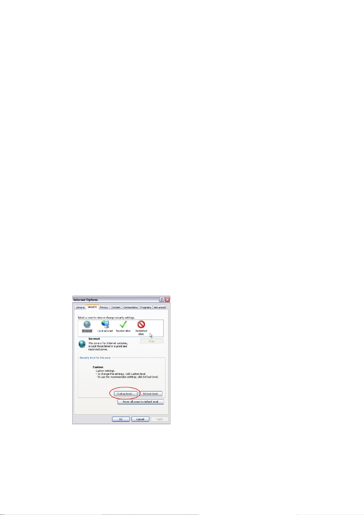
To change the web browser’s security level:
1. In Internet Explorer, click Internet Options on the Tools menu.
2. On the Security tab, click the zone to which you want to assign a web site
under “Select a web content zone to specify its security settings”.
3. Click Custom Level.
4. Change the ActiveX controls and plug-ins options that are signed or
marked as safe to Enable. Change the ActiveX controls and plug-ins
options that are unsigned to Prompt or Disable. Click OK.
- Or -
TruVision 11/31 Series IP Camera FW 5.1 Configuration Manual 5
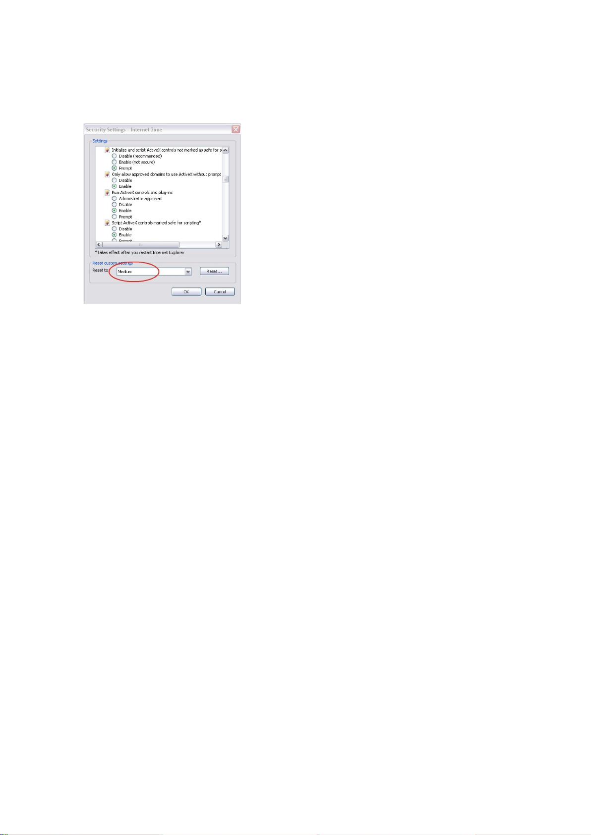
Under Reset Custom Settings, click the security level for the whole zone in
the Reset To box, and select Medium. Click Reset.
Then click OK to the Internet Options Security tab window.
5. Click Apply in the Internet Options Security tab window.
Windows 7 and 8 users
Internet Explorer for Windows 7 and Windows 8 operating systems have
increased security measures to protect your PC from any malicious software
being installed.
To have complete functionality of the web browser interface with Windows 7 and
Windows 8, do the follow i ng :
• Run the Browser interface as an administrator in your workstation
• Add the camera’s IP address to your browser’s list of trusted sites
To add the camera’s IP address to Internet Explorer’s list of trusted sites:
1. Open Internet Explorer.
2. Click Tools, and then Internet Options.
3. Click the Security tab, and then select the Trusted sites icon.
4. Click the Sites button.
5. Clear the “Require server verification (https:) for all sites in this zone box.
6. Enter the IP address in the “Add this website to the zone” field.
7. Click Add, and then click Close.
8. Click OK in the Internet Options dialog window.
9. Connect to the camera for full browser functionality.
6 TruVision 11/31 Series IP Camera FW 5.1 Configuration Manual

Accessing the camera over the internet
Use the web browser to access and configure the camera over the internet.
It is recommended that you change the administrator password once the setup is
complete. Only authorized users should be able to modify camera settings. See
“User management” on page 50 for further information.
To access the camera online:
1. In the web browser enter the camera’s IP address (default is 192.168.1.70).
Use the tool, TruVision Device Finder, enclosed on the CD to find the IP
address of the camera.
The Login dialog box appears.
Note: Ensure that the Active X controls are enabled.
2. Enter your user name and password.
User name: admin
Password: 1234
3. Click Login. The web browser window appears in live view mode.
Overview of the camera web browser
The camera web browser lets you view, record, and play back recorded videos
as well as manage the camera from any PC with Internet access. The browser’s
easy-to-use controls give you quick access to all camera functions. See Figure 1
on page 8.
If there is more than one camera connected over the network, open a separate
web browser window for each individual camera.
TruVision 11/31 Series IP Camera FW 5.1 Configuration Manual 7
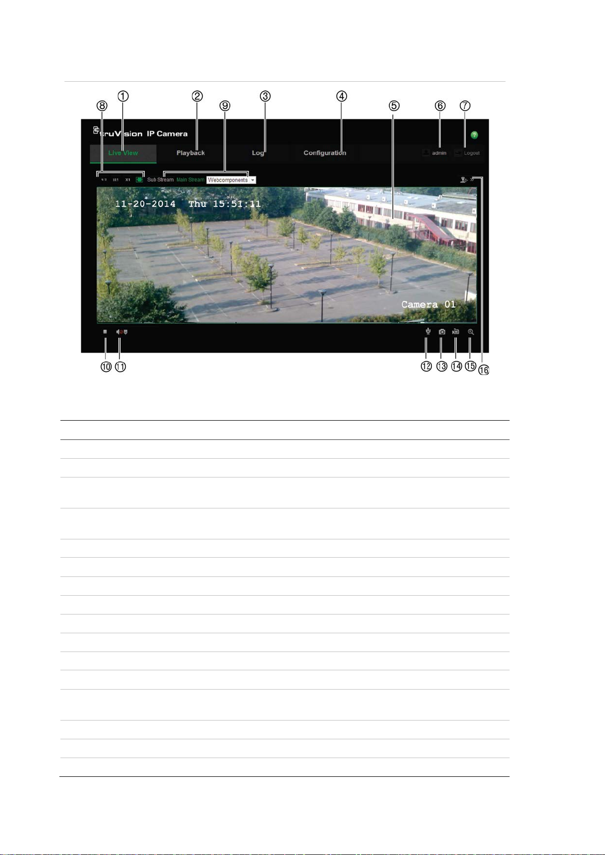
Figure 1: Web browser interface
Table 1: Overview of the web browser interface
Name Description
1. Live view Click to view live video.
2. Playback Click to play back video.
3. Log Click to search for event logs. There are three main types: Alarm,
Exception and Operation.
4. Configuration Click to display the configuration window for setting up the
camera.
5. Viewer View live video. Time, date and camera name are displayed here.
6. Current user Displays current user logged on.
7. Logout Click to log out from the system. This can be done at any time.
8. Aspect ratio Select the aspect
9. Streaming Switch between main stream and substream.
10. Start/stop live view Click to start/stop live view.
11. Audio Adjust volume.
12. Bidirectional audio Turn on/off microphone.
13. Capture Click to take a snapshot of the video. The snapshot will be saved
to the default folder in JPEG format.
14. Start/stop recording Click to record live video.
15. Digital Zoom Click to enable digital zoom.
16. PTZ control Control pan, tilt, zoom actions, and set up presets and tour.
8 TruVision 11/31 Series IP Camera FW 5.1 Configuration Manual
, time settings,
Camera configuration
This chapter explains how to configure the cameras through a web browser.
Once the camera hardware has been installed, configure the camera’s settings
through the web browser. You must have administrator rights in order to
configure the cameras over the internet.
The camera web browser lets you configure the camera remotely using your PC.
Web browser options may vary depending on camera model.
There are two main folders in the configuration panel:
Local configuration
Configuration
Configuration menu overview
Use the Configuration panel to configure the server, network, camera, alarms,
users, transactions and other parameters such as upgrading the firmware. See
Figure 2 and Table 2 below for descriptions of the configuration folders available.
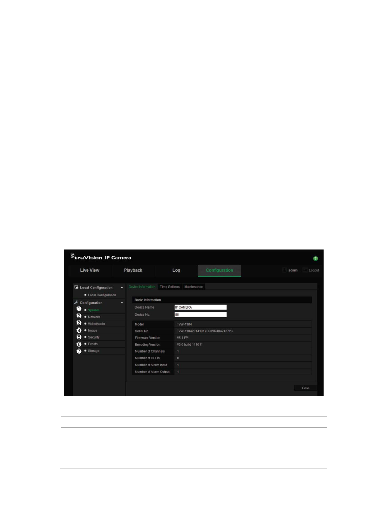
Figure 2: Configuration panel (Device Information tab selected)
Table 2: Overview of the Configuration panel
Configuration folders Description
1. System Defines the camera name and number. Displays basic information on
the device including SN and the current firmware version
maintenance, and serial port parameters. See “System time” on page
12, “Restore default settings” on page 55, and “Upgrade firmware” on
page 56 for more information.
TruVision 11/31 Series IP Camera FW 5.1 Configuration Manual 9

Network
Video/Audio
Image
Security
Events
,
Storage
Configuration folders Description
2.
3.
4.
5.
6.
7.
Defines the network parameters required to access the camera over
the internet. See “Network settings” on page 13 for more information.
Defines recording parameters. See “Recording parameters” on page
23 for more information.
Defines the image parameters, OSD settings, overlay text, and privacy
mask. See “Video image” on page 26, “OSD (On Screen Display)” on
page 29, “Overlay text” on page 30, and “Privacy masks” on page 31
for more information.
Defines who can use the camera, their passwords and access
privileges, RTSP authentication, IP addr ess filter, and Telnet access.
See “Camera management” on page 50 for more information.
Defines motion detection, tamper-proof, alarm input/output, exception,
and snapshot configuration. See “Motion detection alarms” on page 31
“Tamper-proof alarms” on page 35, “Exception alarms” on page 36,
and “Snapshot parameters” on page 43 for more information.
Defines recording schedule, storage management, and NAS
configuration. See “NAS settings” on page 45, “Storage devices” on
page 46, and “Recording schedule” on page 47 for more information.
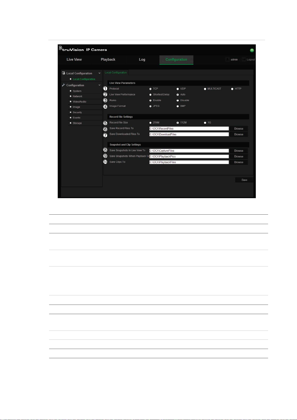
Local configuration
Use the Local menu to manage the protocol type, live view performance and
local storage paths. In the Configuration panel, click Local Configuration to
display the local configuration window. See Figure 3 and Table 3 below for
descriptions of the diff er ent me nu par a met ers.
10 TruVision 11/31 Series IP Camera FW 5.1 Configuration Manual
Protocol
Live View Performance
Rules
It refers to the rules on your local browser. Specify whether or
face will be marked with a green rectangle in live view.
Image Format
Record F
Save
Save
Save
To
Figure 3: Example of a configuration window (Local configuration shown)
Table 3: Overview of the Local configuration window
Parameters Description
Live View Parameters
1.
Specifies the network protocol used.
Options include: TCP, UDP, MULTICAST and HTTP.
2.
Specifies the transmission speed.
Options include: Shortest Delay or Auto.
3.
not to display the colored marks when motion detection, face
detection, and intrusion detection are triggered. For example,
when the rules option is enabled and a face is detected, the
4.
Choose the image format for a snapshot: JPEG or BMP.
Record File Settings
5.
ile Size Specifies the maximum file size.
Options include: 256 MB, 512 MB and 1G.
6.
Record Files to Specifies the directory for recorded files.
7.
Downloaded Files to Specifies the directory for downloaded files.
Picture and Clip Settings
8.
Snapshots In Live View
Specifies the directory for saving snapshots in live view mode.
TruVision 11/31 Series IP Camera FW 5.1 Configuration Manual 11
Save
Playback To
Save Clips To
Parameters Description
9.
10.
Snapshots When
Specifies the directory for saving video clips in playback mode.
Specifies the directory for saving snapshots in playback mode.
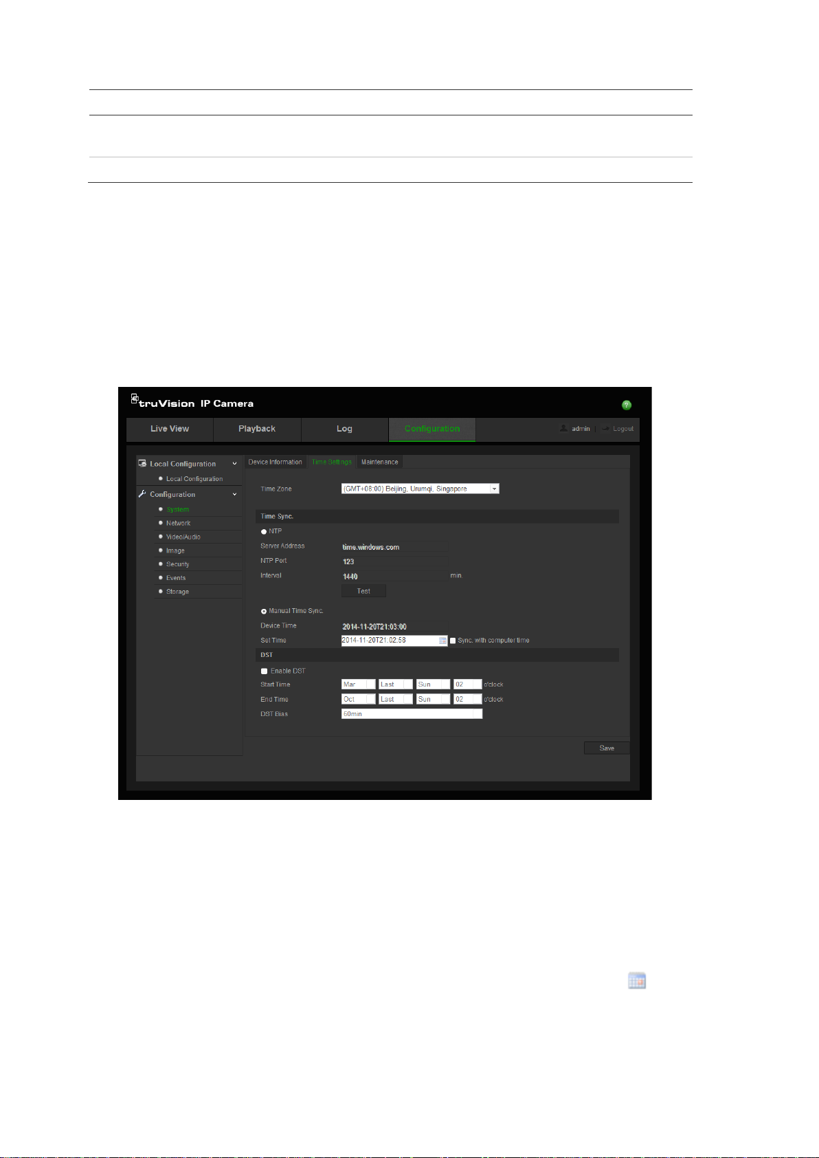
System time
NTP (Network Time Protocol) is a protocol for synchronizing the clocks of
network devices, such as IP cameras and computers. Connecting network
devices to a dedicated NTP time server ensures that they are all synchronized.
To define the system time and date:
1. Click Configuration > System > Time Settings.
2. From the Time Zone drop-down menu, select the time zone that is the
closest to the camera’s location.
3. Under Time Sync, check one of the options for setting the time and date:
Synchronize with an NTP server: Check the NTP enable box and enter the
server NTP address. The time interval can be set from 1 to 10080 minutes.
- Or Set manually: Enabl e the Manual Time Sync function and then click to
set the system time from the pop-up calendar.
Note: You can also check the Sync with computer time checkbox to
synchronize the time of the camera with the time of your computer.
12 TruVision 11/31 Series IP Camera FW 5.1 Configuration Manual
TCP/IP
4. Check Enable DST to enable the DST function, and set the date of the DST
period.
5. Click Save to save changes.
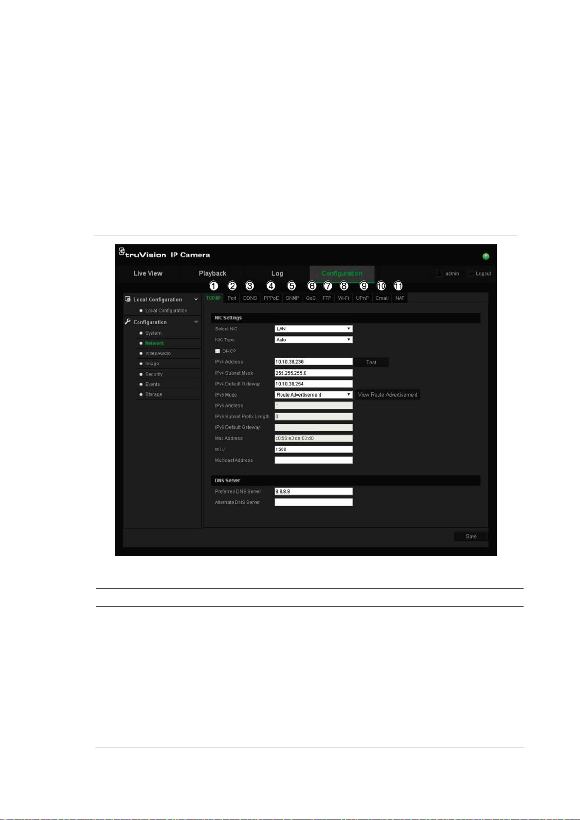
Network settings
Accessing the camera through a network requires that you define certain network
settings. Use the “Network” folder to define the network settings. See Figure 4
and Table 4 below for fur ther in for ma ti on.
Figure 4: Network window (TCP/IP tab shown)
Table 4: Network parameters
Parameters Description
1.
TruVision 11/31 Series IP Camera FW 5.1 Configuration Manual 13
Select NIC: Specifies LAN or WLAN for different network.
NIC Type: Specifies the NIC type. Default is Auto. Other options include:
10M Half-dup, 10M Full-dup, 100M Half-dup and 100M Full-dup.
DHCP: Enable to automatically obtain an IP address and other network
settings from that server.
IPv4 Address: Specifies the IPv4 address of the camera.
IPv4 Subnet Mask: Specifies the IPv4 subnet mask.
IPv4 Default Gateway: Specifies the IPv4 gateway IP address.
IPv6 Mode: Specifies the IPv6 mode, including Manual, DHCP and Router
Advertisement.

IPv6 Address: Specifies the IPv6 address of the camera.
Port
DDNS
PPPoE
SNMP
QoS
FTP
Wi
UPnP
Email
Parameters Description
IPv6 Subnet Prefix Length: Specifies the IPv6 prefix length.
IPv6 Default Gateway: Specifies the IPv6 gateway IP address.
Mac Address: Specifies the mac address of the camera.
MTU: Specifies the valid value range of MTU. Default is 1500.
Multicast Address: Specifies a D-class IP address between 224.0.0.0 to
239.255.255.255. Only specify this option if you are using the multicast
function. Some routers prohibit the use of multicast function in case of a
network storm.
DNS server: Specifies the DNS server for your network.
2.
3.
4.
HTTP Port: The HTTP port is used for remote internet browser access.
Enter the port used for the Internet Explorer (IE) browser. Default value is
80.
RTSP Port: RTSP (Real Time Streaming Protocol) is a network control
protocol designed for use in entertainment and communications systems to
control streaming media servers. Enter the RTSP port value. The default port
number is 554.
HTTPS Port: HTTPS (Hyper Text Transfer Protocol Secure) allows video to
be securely viewed when using a browser. Enter the HTTPS port, value. The
default port number is 443.
Server Port: This is used for remote client software access. Enter the server
port value. The default port number is 8000.
DDNS is a service that maps Internet domain names to IP addresses. It is
designed to support dynamic IP address es, suc h as th ose ass igned by a
DHCP server.
Specifies IP server, DynDNS, and ezDDNS.
DynDNS (Dynamic DNS): Enter the user name and password registered to
the DynDNS web site. The domain name is that of the DynDNS web site.
ezDDNS: Enter the host name. It will automatically register it online.
IPServer: Enter the address of the IP Server.
Retrieves a dynamic IP address.
5.
SNMP is a protocol for managing devices on networks. Enable SNMP to get
camera status and parameter related information.
6.
QoS (Quality of Service) can help solve the network delay and network
congestion by configuring the priority of data sending.
Enable the option in order to solve network delay and network congestion by
configuring the priority of data sending.
7.
Enter the FTP address and folder to which snapshots of the camera can be
uploaded.
8.
9.
-Fi Specifies the wireless network connection parameters.
The UPnP (Universal Plug and Play) protocol allows devices to connect
seamlessly and to simplify the implementation of networks in the home and
corporate environments. With the function enabled, you do not need to
configure the port mapping for each port, and the camera is connected to the
Wide Area Network (WAN) via the router.
Enable and set the friendly name detected.
10.
Specifies the email address to which messages are sent when an alarm
occurs.
14 TruVision 11/31 Series IP Camera FW 5.1 Configuration Manual
NAT
Parameters Description
11.
The UPnP (Universal Plug and Play) protocol allows devices to connect
seamlessly and to simplify the implementation of networks in the home and
corporate environments. With the function enabled, you do not need to
configure the port mapping for each port, and the camera is connected to the
Wide Area Network (WAN) via the router.
Enable and set the friendly name detected.
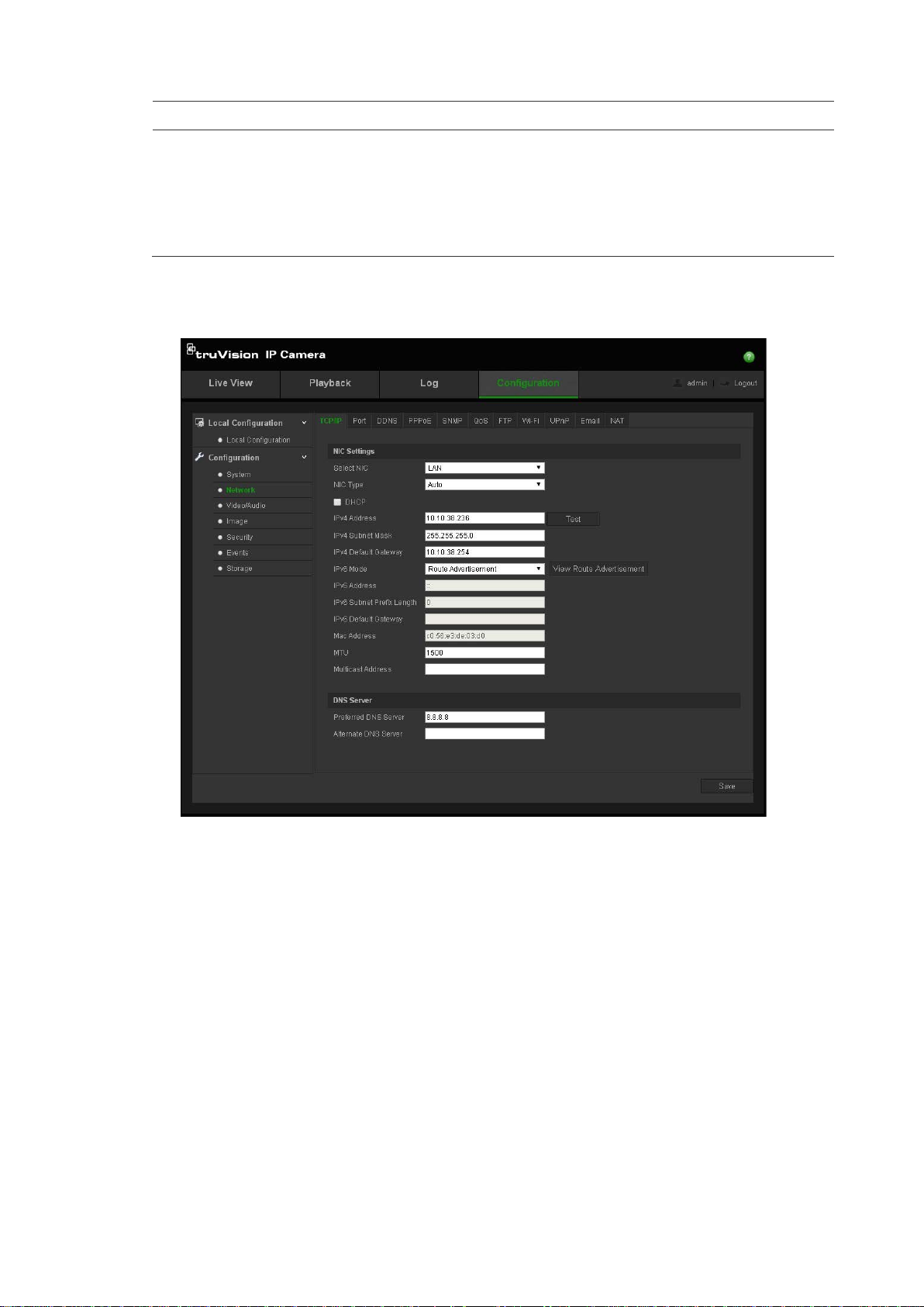
To define the TCP/IP parameters:
1. Click Configuration > Network > TCP/IP.
2. Configure the NIC settings, including the NIC Type, IPv4 settings, IPv6
settings, MTU settings, and Multicast Address.
3. If the DHCP server is available, check DHCP.
4. If the DNS server settings are required for some applications (e.g., sending
email), you should configure the Preferred DNS Server or Alternate DNS
Server.
5. Click Save to save changes.
TruVision 11/31 Series IP Camera FW 5.1 Configuration Manual 15
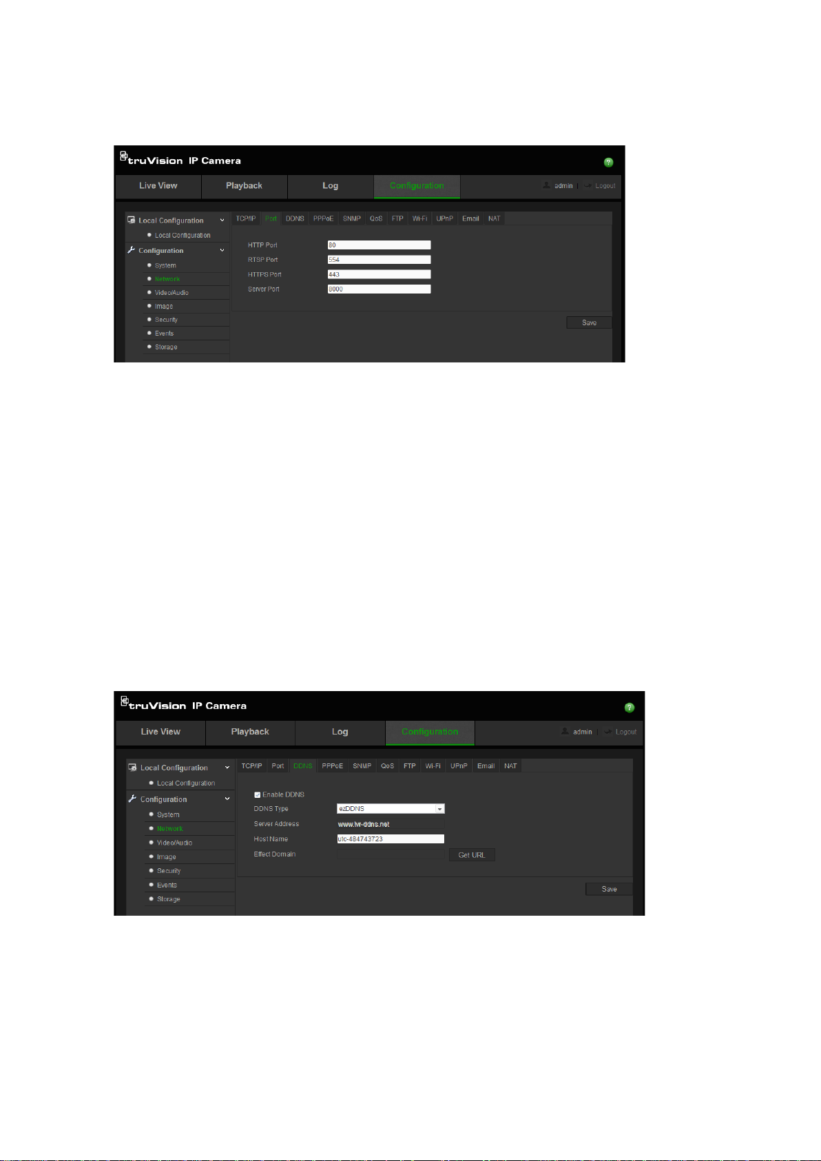
To define the port parameters:
1. Click Configuration > Network > Port.
2. Set the HTTP port, RTSP port, HTTPS port and Server port of the camera.
HTTP Port: The default port number is 80. It can be changed to any port
number that is not occupied.
RTSP Port: The default port number is 554. It can be changed to any port
number in the range from 1 to 65535.
HTTPS Port: The default port number is 443. It can be changed to any port
number that is not occupied.
Server Port: The default server port number is 8000. It can be changed to
any port number in the range from 2000 to 65535.
3. Click Save to save changes.
To define the DDNS parameters:
1. Click Configuration > Network > DDNS.
2. Check Enable DDNS to enable this feature.
3. Select DDNS Type. Two options are available: DynDNS and IPServer.
• DynDNS: Enter the user name and password registered to the DynDNS
web site. The domain name is that of the DynDNS web site.
• ezDDNS: Enter the host name. It will automatically register it online.
16 TruVision 11/31 Series IP Camera FW 5.1 Configuration Manual
• IPServer: Enter the address of the IP Server.
4. Click Save to save changes.
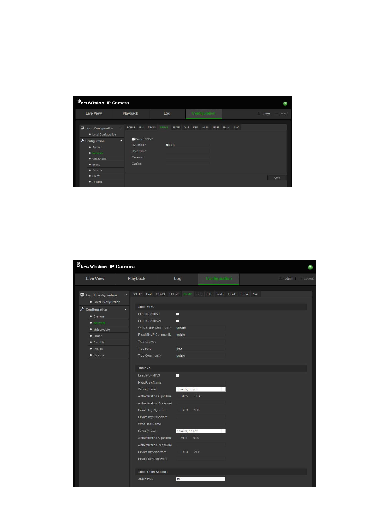
To define the PPPoE parameters:
1. Click Configuration > Network > PPPoE.
2. Check Enable PPPoE to enable this feature.
3. Enter User Name, Password, and Confirm password for PPPoE access.
4. Click Save to save changes.
To define the SNMP parameters:
1. Click Configuration > Network > SNMP.
TruVision 11/31 Series IP Camera FW 5.1 Configuration Manual 17
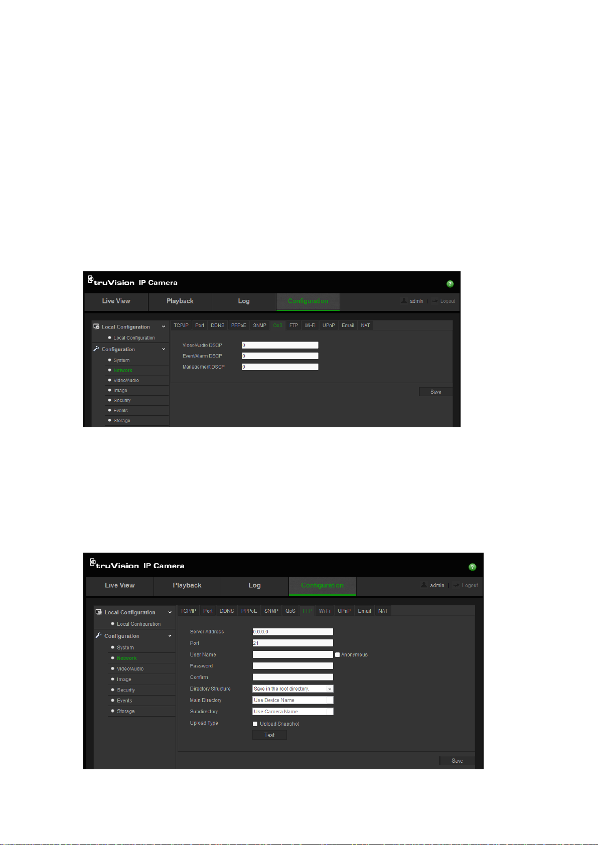
2. Select the corresponding version of SNMP: v1, v2c or v3.
3. Configure the SNMP settings. The configuration of the SNMP software should
be the same as the settings you configure here.
4. Click Save to save changes.
Note: Before setting the SNMP, please download the SNMP software and ensure
that you can receive the camera information via the SNMP port. By setting the
Trap Address, the camera can send the alarm event and exception messages to
the surveillance center. The SNMP version you select should be the same as
that of the SNMP software.
To define the QoS parameters:
1. Click Configuration > Network > QoS.
2. Configure the QoS settings, including Video / Audio DSCP, Event / Alarm
DSCP and Management DSCP. The valid value range of the DSCP is 0-63.
The bigger the DSCP value is the higher the priority is.
3. Click Save to save changes.
To define the FTP parameters:
1. Click Configuration > Network > FTP.
18 TruVision 11/31 Series IP Camera FW 5.1 Configuration Manual
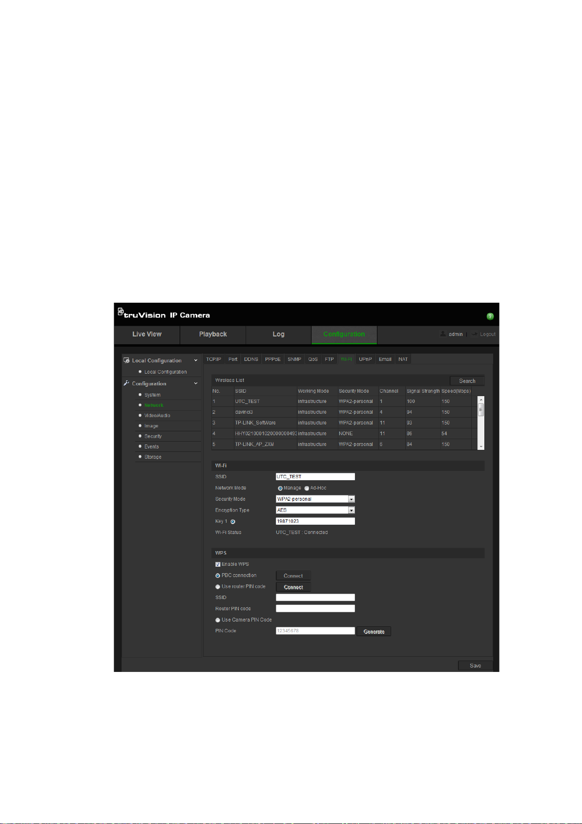
2. Configure the FTP settings, including server address, port, user name,
password, directory, and upload type.
Anonymous: Check the checkbox to enable the anonymous access to the
FTP server.
Directory: In the Directory Structure field, you can select the root directory,
parent directory and child directory. When the parent directory is selected,
you have the option to use the Device Name, Device Number or Device IP for
the name of the directory; and when the child directory is selected, you can
use the Camera Name or Camera No. as the name of the directory.
Upload type: To enable uploading the snapshots to the FTP server.
3. Click Save to save changes.
To define the Wi-Fi parameters:
1. Click Configuration > Network > Wi-Fi.
Note: When configuring the Wi-Fi settings for the first time, connect the
camera to the router via a network cable and then open the web browser to
complete the Wi-Fi setup by clicking Save. When the Wi-Fi Status changes
from “Disconnected” to “Connected”, the wireless connection is successfully
set up.
TruVision 11/31 Series IP Camera FW 5.1 Configuration Manual 19
Loading...