


 Loading...
Interlogix TVD-5405, TVD-5406, TVD-5407, TVD-5408, TVD-5401 User Manual
...TruVision Series 4 IP
Camera Configuration
Manual
P/N 1073194-EN • REV B • ISS 25AUG16

Copyright © 2016 United Technologies Corporation.
Interlogix is part of UTC Climate, Controls & Security, a unit of United Technologies Corporation. All rights reserved.
Trademarks and Trade names used in this document may be trademarks or patents registered trademarks of the manufacturers or vendors of the
respective products.
Manufacturer Interlogix
2955 Red Hill Avenue, Costa Mesa, CA 92626-5923, USA
Authorized EU manufacturing representative: UTC Building & Industrial Systems B.V. Kelvinstraat 7, 6003 DH Weert, The Netherlands
Certification
Contact information For contact information, see www.interlogix.com or www.utcfssecurityproducts.eu.
2 |
TruVision Series 4 IP Camera Configuration Manual |
Content
Introduction 3
Default settings to access the camera 4
Network access 5
Checking your web browser security level 5
Accessing the camera over the internet 6
Overview of the camera web browser 6
Camera configuration 9
Configuration menu overview 9
Local configuration 10
System time 12
Network settings 13
Recording parameters 20
Video image 24
OSD (On Screen Display) 27
Text overlay 28
Privacy masks 29
Picture overlay 30
Motion detection alarms 31
Tamper-proof alarms 37
Exception alarms 38
Alarm inputs and outputs 39
Face detection 40
Audio exception detection 42
Cross line detection 44
Intrusion detection 45
Defocus detection 47
Scene change detection 48
Region Entrance Detection 50
Region Exiting Detection 52
Unattended Baggage Detection 54
Object Removal Detection 56
Snapshot parameters 58
NAS settings 60
Storage devices 61
Recording schedule 62
RS-485 settings 64
Object counting 64
Camera management |
66 |
User management 66 |
|
RTSP authentication 68 |
|
IP address filter 69 |
|
TruVision Series 4 IP Camera Configuration Manual |
1 |
Defining the security service 70
Restore default settings 70
Import/export a configuration file 71
Upgrade firmware 71
Reboot camera 73
Camera operation 74
Logging on and off 74
Live view mode 74
Playing back recorded video 75
Searching event logs 77
Operating PTZ control 79
2 |
TruVision Series 4 IP Camera Configuration Manual |
Introduction
This is the configuration manual for the following TruVision IP camera models:
TVC-5401 (2MPX low light camera)
TVC-5402 (3MPX box camera)
TVC-5403 (5MPX box camera)
TVB-5401
TVB-5402
TVB-5403
TVB-5404
TVB-5405
TVD-5401
TVD-5402
TVD-5403
TVD-5404
TVD-5405
TVD-5406
TVD-5407
TVD-5408
(2MPX low light bullet camera) (2MPX low light bullet camera) (3MPX motorized lens bullet camera) (3MPX motorized lens bullet camera) (5MPX motorized lens bullet camera)
(2MPX low light indoor mini dome) (3MPX motorized lens mini indoor dome) (5MPX indoor mini dome)
(2MPX low light motorized lens dome) (2MPX low light motorized lens dome) (3MPX WDR motorized lens dome)
(3MPX WDR motorized lens dome) (5MPX motorized lens mini dome)
TruVision Series 4 IP Camera Configuration Manual |
3 |
Default settings to access the camera
Default credentials
The camera comes with a user account with administrative rights for configuring all options on the camera. The user name is “admin” and the password is “1234”. It is highly recommended that the default password be changed during initial setup for enhanced security.
Default network settings
The network settings are:
IP address: 192.168.1.70
Subnet mask: 255.255.255.0
Gateway address: 192.168.1.1 Ports used:
Browser |
TruVision Navigator |
RTSP: 554 |
RTSP: 554 |
HTTP: 80 |
Server/client control port: 8000 |
Please see “Overview of the camera web browser” on page 6 for further information.
4 |
TruVision Series 4 IP Camera Configuration Manual |
Network access
This manual explains how to configure the camera over the network with a web browser.
TruVision IP cameras can be configured and controlled using Microsoft Internet Explorer (IE) and other browsers. The procedures described use Microsoft Internet Explorer (IE) web browser.
Checking your web browser security level
When using the web browser interface, you can install ActiveX controls to connect and view video using Internet Explorer. However, you may not be able to download data, such as video and images, due to the browser’s security settings. Consequently you should check the security level of your browser so that you are able to interact with the cameras over the web and, if necessary, modify the Active X settings.
Configuring IE ActiveX controls
You should confirm the ActiveX settings of your web browser.
To change the web browser’s security level:
1.In Internet Explorer click Internet Options on the Tools menu.
2.On the Security tab, click the zone to which you want to assign a web site under “Select a web content zone to specify its security settings”.
3.Click Custom Level.
4.Change the ActiveX controls and plug-ins options that are signed or marked as safe to Enable. Change the ActiveX controls and plug-ins options that are unsigned to Prompt or Disable. Click OK.
- Or -
Under Reset Custom Settings, click the security level for the whole zone in the Reset To box, and select Medium. Click Reset.
Then click OK to the Internet Options Security tab window.
5. Click Apply in the Internet Options Security tab window.
Windows users
Internet Explorer for Windows 7, Windows 8, and Windows 10 operating systems have increased security measures to protect your PC from any malicious software being installed.
To have complete functionality of the web browser interface with Windows 7, Windows 8, and Windows 10 do the following:
•Run the Browser interface as an administrator on your workstation
•Add the camera’s IP address to your browser’s list of trusted sites
TruVision Series 4 IP Camera Configuration Manual |
5 |
To add the camera’s IP address to Internet Explorer’s list of trusted sites:
1.Open Internet Explorer.
2.Click Tools, and then Internet Options.
3.Click the Security tab and then select the Trusted sites icon.
4.Click the Sites button.
5.Clear the “Require server verification (https:) for all sites in this zone box.
6.Enter the IP address in the “Add this website to the zone” field.
7.Click Add, and then click Close.
8.Click OK in the Internet Options dialog window.
9.Connect to the camera for full browser functionality.
Accessing the camera over the network
Use the web browser to access and configure the camera over the internet.
It is recommended that you change the administrator password once the setup is complete. Only authorized users should be able to modify camera settings. See “User management” on page 66 for further information.
To access the camera online:
1.In the web browser enter the camera’s IP address (default is 192.168.1.70). Use the TruVision Device Manager included on the CD to find the IP address of the camera and assign it a new address on the local network, if desired.
The Login dialog box appears.
Note: Ensure that the Active X controls are enabled.
2.Enter your user name and password.
User name: admin Password: 1234
3.Click Login. The web browser window appears in live view mode.
Overview of the camera web browser
The camera web browser lets you view, record, and play back recorded videos as well as manage the camera from any PC with access to the same network as the camera. The browser’s easy-to-use controls give you quick access to all camera functions. See Figure 1 on page 7.
If there is more than one camera connected over the network, open a separate web browser window for each individual camera.
6 |
TruVision Series 4 IP Camera Configuration Manual |

Figure 1: Web browser interface
|
|
|
|
|
|
|
|
|
|
|
|
|
|
|
|
|
|
|
|
|
|
|
|
|
|
|
|
|
|
|
|
|
|
|
|
|
|
|
|
|
|
|
|
|
|
|
|
|
|
|
|
|
|
|
|
|
|
|
|
|
|
|
|
|
|
|
|
|
|
|
|
|
|
|
|
|
|
|
|
|
|
|
|
|
|
|
|
|
|
|
|
|
|
|
|
|
|
|
|
|
|
|
|
|
|
|
|
|
|
|
|
|
|
|
|
|
|
|
|
|
|
|
|
|
|
|
|
|
|
|
|
|
|
|
|
|
|
|
|
|
|
|
|
|
|
|
|
|
|
|
|
|
|
|
|
|
|
|
|
|
|
|
|
|
|
|
|
|
|
|
|
|
|
|
|
|
|
|
|
|
|
|
|
|
|
|
|
|
|
Name |
Description |
|
|
|||||||||||||||
|
|
|
|
|
|
|
|
|
|
|
|
|
|
|
|
|
|
|
1. |
Live view |
Click to view live video. |
|
|
||||||||||||||
|
|
|
|
|
|
|
|
|
|
|
|
|
|
|
|
|
|
|
2. |
Playback |
Click to play back video. |
|
|
||||||||||||||
|
|
|
|
|
|
|
|
|
|
|
|
|
|
|
|
|
|
|
3. |
Log |
Click to search for event logs. There are three main types: Alarm, |
|
|
||||||||||||||
|
|
|
|
|
Exception and Operation. |
|
|
|||||||||||
|
|
|
|
|
|
|
|
|
|
|
|
|
|
|
|
|
|
|
4. |
Configuration |
Click to display the configuration window for setting up the camera. |
|
|
||||||||||||||
|
|
|
|
|
|
|
|
|
|
|
|
|
|
|
|
|
|
|
5. |
Viewer |
View live video. Time, date and camera name are displayed here. |
|
|
||||||||||||||
|
|
|
|
|
|
|
|
|
|
|
|
|
|
|
|
|
|
|
6. |
Current user |
Displays current user logged on. |
|
|
||||||||||||||
|
|
|
|
|
|
|
|
|
|
|
|
|
|
|
|
|
|
|
7. |
Logout |
Click to log out from the system. This can be done at any time. |
|
|
||||||||||||||
|
|
|
|
|
|
|
|
|
|
|
|
|
|
|
|
|
|
|
8. |
PTZ controls |
Direction actions, zoom, focus, iris, light and wiper control. |
|
|
||||||||||||||
|
|
|
|
|
Note: Direction actions, light, and wiper control can be used if the |
|
|
|||||||||||
|
|
|
|
|
camera supports RS-485 and external pan/tilt unit, light or wiper is |
|
|
|||||||||||
|
|
|
|
|
installed. |
|
|
|||||||||||
|
|
|
|
|
|
|
|
|
|
|
|
|
|
|
|
|
|
|
9. |
Display Control |
Click each tab to adjust the layout and the stream type of the live |
|
|
||||||||||||||
|
|
|
|
|
view. You can also click the drop-down menu to select the plug-in. |
|
|
|||||||||||
|
|
|
|
|
For IE (internet explorer) users, web components and QuickTime® |
|
|
|||||||||||
|
|
|
|
|
are selectable. For non-IE users, web components, QuickTime, VLC |
|
|
|||||||||||
|
|
|
|
|
or MJPEG are selectable, if they are supported by the web browser. |
|
|
|||||||||||
|
|
|
|
|
|
|
|
|
|
|
|
|
|
|
|
|
|
|
10. |
Start/stop live view |
Click to start/stop live view. |
|
|
||||||||||||||
|
|
|
|
|
|
|
|
|
|
|
|
|
|
|
|
|
|
|
11. |
Audio |
Adjust the volume. |
|
|
||||||||||||||
|
|
|
|
|
|
|
|
|
|
|
|
|
|
|
|
|
|
|
12. |
Manual alarm |
Turn on/off the alarm |
|
|
||||||||||||||
|
|
|
|
|
|
|
|
|
|
|
|
|
|
|
|
|
|
|
13. |
Bidirectional audio |
Turn on/off the local microphone (if supported). |
|
|
||||||||||||||
|
|
|
|
|
|
|
|
|
|
|
|
|
|
|
|
|
|
|
14. |
Capture |
Click to take a snapshot of the video. The snapshot will be saved to |
|
|
||||||||||||||
|
|
|
|
|
the default folder in JPEG or BMP format. |
|
|
|||||||||||
|
|
|
|
|
|
|
|
|
|
|
|
|
|
|
|
|
||
TruVision Series 4 IP Camera Configuration Manual |
7 |
|||||||||||||||||

Name |
Description |
|
|
|
|
15. |
Start/stop |
Click to record live video. |
|
recording |
|
|
|
|
16. |
Digital zoom |
Click to enable digital zoom. |
|
|
|
8 |
TruVision Series 4 IP Camera Configuration Manual |
Camera configuration
This chapter explains how to configure the cameras through a web browser.
Once the camera hardware has been installed, configure the camera’s settings through the web browser. You must have administrator rights in order to configure the cameras over the internet.
The camera web browser lets you configure the camera remotely using your PC. Web browser options may vary depending on camera model.
There are two main menus in the configuration panel:
Local configuration
Configuration
Configuration menu overview
Use the Configuration panel to configure the network, camera settings, alarms, users, transactions and other parameters such as upgrading the firmware. See Figure 2 below for descriptions of the configuration menus available.
Figure 2: Configuration window (Device Information tab selected)
Configuration menus |
Description |
|
|
|
|
|
|
1. |
System |
Defines basic device information including SN, the current firmware |
|
|
|
version, time settings, maintenance, and serial port parameters. See |
|
|
|
“System time” on page 12 for further information. |
|
|
|
|
|
2. |
Network |
Defines the parameters required to access the camera over a network. |
|
|
|
See “Network settings” on page 13 for further information on the setup. |
|
|
|
|
|
3. |
Video/Audio |
Defines recording parameters. |
|
TruVision Series 4 IP Camera Configuration Manual |
9 |
||

Configuration menus |
Description |
|
|
|
|
4. |
Image |
Defines the image parameters, OSD settings, overlay text, and privacy |
|
|
mask. See “Video image” on page 24 for further information on the |
|
|
setup. |
|
|
|
5. |
Security |
Defines who can access and use the camera, their passwords and |
|
|
access privileges, RTSP authentication, IP address filter, and SSH. |
|
|
|
6. |
Basic Event |
Defines Motion Detection, Tamper-proof, Alarm Input/Output, and |
|
|
Exceptions. See “Motion detection alarms” on page 31, “Tamper-proof |
|
|
alarms” on page 37, and “Exception alarms” on page 38. |
|
|
|
7. |
Smart Event |
Defines Defocus Detection, Scene Change Detection, Face Detection, |
|
|
Cross Line, Intrusion Detection, Region Entrance Detection, Region |
|
|
Exiting Detection, Unattended Baggage Detection and Object Removal |
|
|
Detection. |
|
|
|
8. |
Storage |
Defines recording schedule, storage management, NAS configuration |
|
|
and snapshot. |
|
|
|
9. |
Counting |
Defines the people/object counting parameters. |
|
|
|
Local configuration
Use the Local menu to manage the protocol type, live view performance and local storage paths. In the Configuration panel, click Local Configuration to display the local configuration window. See Figure 3 below for descriptions of the different menu parameters.
Figure 3: Example of the Local configuration window
|
|
|
10 |
TruVision Series 4 IP Camera Configuration Manual |
|

Parameters |
Description |
|
|
|
|
Live View Parameters |
|
|
|
|
|
1. |
Protocol |
Specifies the network protocol used. |
|
|
Options include: TCP, UDP, MULTICAST and HTTP. |
|
|
|
2. |
Live View Performance |
Specifies the transmission speed. |
|
|
Options include: Shortest Delay or Auto. |
|
|
|
3. |
Rules |
Enable or disable the display of intelligent metadata in Live |
|
|
View mode on the browser. Specify whether or not to display |
|
|
the colored marks for events such as motion detection, face |
|
|
detection, and intrusion detection while viewing video live in |
|
|
the browser. For example, when the Rules option is enabled, |
|
|
Face Detection is enabled, and a face is detected, the face will |
|
|
be marked with a green rectangle in Live View. |
|
|
|
4. |
Image Format |
Choose the image format for a snapshot: JPEG or BMP. |
|
|
|
Record File Settings |
|
|
|
|
|
5. |
Record File Size |
Specifies the maximum file size for downloaded and recorded |
|
|
video files. |
|
|
Options include: 256 MB, 512 MB and 1G. |
|
|
|
6. |
Save Record Files to |
Specifies the directory for recorded files. |
|
|
|
7. |
Save Downloaded Files to |
Specifies the directory for downloaded files. |
|
|
|
Snapshot and Clip Settings |
|
|
|
|
|
8. |
Save Snapshots In Live |
Specifies the directory for saving snapshots in live view mode. |
|
View To |
|
|
|
|
9. |
Save Snapshots When |
Specifies the directory for saving snapshots in playback mode. |
|
Playback To |
|
|
|
|
10. |
Save Clips To |
Specifies the directory for saving video clips in playback mode. |
|
|
|
TruVision Series 4 IP Camera Configuration Manual |
11 |
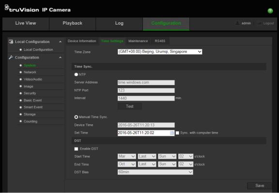
System time
NTP (Network Time Protocol) is a protocol for synchronizing the clocks of network devices, such as IP cameras and computers. Connecting network devices to a dedicated NTP time server ensures that they are all synchronized.
To define the system time and date:
1. From the menu toolbar, click Configuration > System > Time Settings.
2.From the Time Zone drop-down menu, select the time zone that corresponds to the camera’s location.
3.Under Time Sync, check one of the options for setting the time and date:
Synchronize with an NTP server: Check the NTP enable box and enter the server NTP address. The time interval can be set from 1 to 10080 minutes.
- Or -
Set manually: Enable the Manual Time Sync function and then click  to set the system time from the pop-up calendar.
Note: You can also check the Sync with computer time checkbox to synchronize the time of the camera with the time of your computer.
4.Check Enable DST to enable the DST (Daylight Savings Time) function, and set the date of the DST period.
5.Click Save to save changes.
12 |
TruVision Series 4 IP Camera Configuration Manual |

Network settings
Accessing the camera through a network requires that you define certain network settings. Use the “Network” menu to define the network settings. See Figure 4 below for further information.
Figure 4: Network window (TCP/IP tab shown)
Menu tabs |
Description |
|
|
|
|
1. TCP/IP |
NIC Type: Enter the NIC type. Default is Auto. Other options include: 10M |
|
|
Half-dup, 10M Full-dup, 100M Half-dup and 100M Full-dup. |
|
|
DHCP: Enable to automatically obtain an IP address and other network |
|
|
settings from that server. |
|
|
IPv4 Address: Enter the IPv4 address of the camera. |
|
|
IPv4 Subnet Mask: Enter the IPv4 subnet mask. |
|
|
IPv4 Default Gateway: Enter the IPv4 gateway IP address. |
|
|
IPv6 Mode: Enter the IPv6 mode: Manual, DHCP or Router |
|
|
Advertisement. |
|
|
IPv6 Address: Enter the IPv6 address of the camera. |
|
|
IPv6 Subnet Prefix Length: Enter the IPv6 prefix length. |
|
|
IPv6 Default Gateway: Enter the IPv6 gateway IP address. |
|
|
Mac Address: Enter the MAC address of the devices. |
|
|
MTU: Enter the valid value range of MTU. Default is 1500. |
|
|
Multicast Address: Enter a D-class IP address between 224.0.0.0 to |
|
TruVision Series 4 IP Camera Configuration Manual |
13 |
|

Menu tabs |
Description |
|
|
|
|
|
|
239.255.255.255. Only specify this option if you are using the multicast |
|
|
function. Some routers prohibit the use of multicast function in case of a |
|
|
network storm. |
|
|
Enable Multicast Discovery: Enables the automatic detection of the |
|
|
online network camera via private multicast protocol in the LAN. |
|
|
DNS server: Specifies the DNS server for your network. |
|
|
See page 15 for setup information. |
|
|
|
2. |
Port |
HTTP Port: The HTTP port is used for remote browser access. Enter the |
|
|
port used for the Internet Explorer (IE) browser. Default value is 80. |
|
|
RTSP Port: RTSP (Real Time Streaming Protocol) is a network control |
|
|
protocol designed for use in entertainment and communications systems |
|
|
to control streaming media servers. Enter the RTSP port value. The |
|
|
default port number is 554. |
|
|
HTTPS Port: HTTPS (Hyper Text Transfer Protocol Secure) allows video |
|
|
to be securely viewed when using a browser. Enter the HTTPS port, |
|
|
value. The default port number is 443. |
|
|
Server Port: This is used for remote client software access. Enter the |
|
|
server port value. The default port number is 8000. |
|
|
Alarm Server IP: Specifies the IP address of the alarm host. |
|
|
Alarm Server Port: Specifies the port of the alarm host. |
|
|
See page 15 for setup information. |
|
|
|
3. |
DDNS |
DDNS is a service that maps Internet domain names to IP addresses. It is |
|
|
designed to support dynamic IP addresses, such as those assigned by a |
|
|
DHCP server. |
|
|
Specify IP server, DynDNS, and ezDDNS. |
|
|
DynDNS (Dynamic DNS): Manually create your own host name. You will |
|
|
first need to create a user account using the hosting web site, |
|
|
DynDNS.org. |
|
|
ezDDNS: Activate the DDNS auto-detection function to set up a dynamic |
|
|
IP address. The server is set up to assign an available host name to your |
|
|
recorder. |
|
|
IPServer: Enter the address of the IP Server. |
|
|
See page 16 for setup information. |
|
|
|
4. |
PPPoE |
Retrieves a dynamic IP address. See page 16 for setup information. |
|
|
|
5. |
SNMP |
SNMP is a protocol for managing devices on networks. Enable SNMP to |
|
|
get camera status and parameter related information. See page 16 for |
|
|
setup information. |
|
|
|
6. |
802.1.X |
When the feature is enabled, the camera data is secured and user |
|
|
authentication is needed when connecting the camera to the network. See |
|
|
page 16 for setup information. |
|
|
|
7. |
QoS |
QoS (Quality of Service) can help solve the network delay and network |
|
|
congestion by configuring the priority of data sending. |
|
|
Enable the option in order to solve network delay and network congestion |
|
|
by configuring the priority of data sending. |
|
|
See page 17 for setup information. |
|
|
|
8. |
FTP |
Enter the FTP address and folder to which snapshots of the camera can |
|
|
be uploaded. See page 17 for setup information. |
|
|
|
14 |
TruVision Series 4 IP Camera Configuration Manual |

Menu tabs |
Description |
|
|
|
|
9. |
UPnP |
The UPnP (Universal Plug and Play) protocol allows devices to connect |
|
|
seamlessly and to simplify the implementation of networks in the home |
|
|
and corporate environments. With the function enabled, you do not need |
|
|
to configure the port mapping for each port, and the camera is connected |
|
|
to the Wide Area Network (WAN) via the router. |
|
|
Enable and set the friendly name detected. |
|
|
See page 17 for setup information. |
|
|
|
10. |
Enter the email address to which messages are sent when an alarm |
|
|
|
occurs. See page 18 for setup information. |
|
|
|
11. |
NAT |
A NAT (Network Address Translation) is used for network connection. |
|
|
Select the port mapping mode: auto or manual. See page 19 for setup |
|
|
information. |
|
|
|
12. |
HTTPS |
Specifies authentication of the web site and its associated web server, |
|
|
which protects against Man-in-the-middle attacks. |
|
|
|
To define the TCP/IP parameters:
1.From the menu toolbar, click Configuration > Network > TCP/IP.
2.Configure the NIC settings, including the NIC Type, IPv4 settings, IPv6 settings, MTU settings, and Multicast Address.
3.If a DHCP server is available, check DHCP.
4.If the DNS server settings are required for some applications (e.g., sending email), you should configure the Preferred DNS Server or Alternate DNS Server.
5.Click Save to save changes.
To define the port parameters:
1.In Configuration > Network, click the Port tab to open its window.
2.Set the HTTP port, RTSP port, HTTPS port and Server port of the camera.
HTTP Port: The default port number is 80, and it can be changed to any port No. which is not occupied.
RTSP Port: The default port number is 554. It can be changed to any port number in the range from 1 to 65535.
HTTPS Port: The default port number is 443. It can be changed to any port number that is not occupied.
Server Port: The default server port number is 8000. It can be changed to any port number in the range from 2000 to 65535.
3.Enter the IP address and port if you want to upload the alarm information to the remote alarm host. Also check the Notify Alarm Recipient option in the normal Linkage of each event page.
4.Click Save to save changes.
TruVision Series 4 IP Camera Configuration Manual |
15 |
To define the DDNS parameters:
1.From the menu toolbar, click Configuration > Network > DDNS.
2.Check Enable DDNS to enable this feature.
3.Select DDNS Type. Two options are available: DynDNS and IPServer.
• Select DDNS Type. Select one of the follow options:
•DynDNS: Enter the DDNS server address, members.ddns.org, which is used to notify DDNS about changes to your IP address, the host name for your camera, the port number (443 (HTTPS)), and your user name and password used to log into your DynDNS account. The domain name displayed under “Host Name” is that which you created on the DynDNS web site.
•ezDDNS: Enter the desired host name under “Host Name”. The default host name is utc-serial number. The new host name is registered when you click Save.
Note: The default server address is www.tvr-ddns.net, which cannot be changed. 4. Click Save to save changes.
To define the PPPoE parameters:
1.From the menu toolbar, click Configuration > Network > PPPoE.
2.Check Enable PPPoE to enable this feature.
3.Enter User Name, Password, and Confirm password for PPPoE access.
4.Click Save to save changes.
To define the SNMP parameters:
1.From the menu toolbar, click Configuration > Network > SNMP.
2.Select the corresponding version of SNMP: v1, v2c or v3.
3.Configure the SNMP settings. The configuration of the SNMP software should be the same as the settings you configure here.
4.Click Save to save changes.
Note: Before configuring SNMP, test your SNMP monitoring software and attempt to receive the camera information via the SNMP port. By setting the Trap Address, the camera can send the alarm event and exception messages to the SNMP monitoring software. The SNMP version you select should be the same as that supported by the SNMP software.
To define the 802.1x parameters:
1.From the menu toolbar, click Configuration > Network > 802.1X.
2.Check Enable IEEE 802.1X to enable the feature.
3.Configure the 802.1X settings, including EAPOL version, user name, and password. The EAPOL version must be identical with that of the router or the switch.
4.Click Save to save changes.
16 |
TruVision Series 4 IP Camera Configuration Manual |
Note: The switch or router to which the camera is connected must support the IEEE 802.1X standard, and a server must be configured. Please apply and register a user name and password for 802.1X in the server.
To define the QoS parameters:
1.From the menu toolbar, click Configuration > Network > QoS.
2.Configure the QoS settings, including Video / Audio DSCP, Event / Alarm DSCP and Management DSCP. The valid value range of the DSCP is 0-63. The bigger the DSCP value, the higher the priority.
3.Click Save to save changes.
To define the FTP parameters:
1.You must have an FTP server configured and available on the network in order to use the FTP feature
2.From the menu toolbar, click Configuration > Network > FTP.
3.Configure the FTP settings, including server address, port, user name, password, directory, and upload type.
Anonymous: Check the checkbox to enable the anonymous access to the FTP server.
Directory: In the Directory Structure field, you can select the root directory, Main directory and Subdirectory. When the Main directory is selected, you have the option to use the Device Name, Device Number or Device IP for the name of the directory; and when the Subdirectory is selected, you can use the Camera Name or Camera No. as the name of the directory.
Upload Type: To enable uploading the snapshots to the FTP server.
4.Click Save to save changes.
To define the UPnP parameters:
1.Click Configuration > Network > UPnP.
2.Check the checkbox to enable the UPnP function. The name of the device when detected online can be edited.
3.Click Save to save changes.
TruVision Series 4 IP Camera Configuration Manual |
17 |

To set up the email parameters:
1. In Configuration > Network, click the Email tab to open its window.
2.Configure the following settings: Sender: The name of the email sender.
Sender’s Address: The email address of the sender. SMTP Server: The SMTP Server, IP address or host name. SMTP Port: The SMTP port. The default is 25.
Enable SSL: Check the checkbox to enable SSL if it is required by the SMTP server.
Attached Snapshot: Check the checkbox of Attached Snapshot if you want to send emails with attached alarm images.
Interval: This is the time between two actions of sending attached images.
Authentication: If your email server requires authentication, check this checkbox to use authentication to log in to this server. Enter the login user name and password.
User Name: The user name to log in to the server where the images are uploaded. Password: Enter the password.
Confirm: Confirm the password.
18 |
TruVision Series 4 IP Camera Configuration Manual |
Receiver1: The name of the first user to be notified.
Receiver’s Address1: The email address of the first user to be notified. Receiver2: The name of the second user to be notified.
Receiver’s Address2: The email address of the second user to be notified. Receiver3: The name of the third user to be notified.
Receiver’s Address3: The email address of the third user to be notified.
3.Click Test to test the email parameters.
4.Click Save to save changes.
To set up the NAT parameters:
1.Click Configuration > Network > NAT.
2.Check the checkbox to enable the NAT function.
3.Select Port Mapping Mode to be Auto or Manual. When you choose Manual mode, you can configure an external port of your choice.
4.Click Save to save changes.
To set up the HTTPS parameters:
1. In the Network folder, click the HTTPS tab to open its window.
2.To create a self-signed certificate:
Click the Create button beside “Create Self-signed Certificate”. Enter the country, host name/IP, validity and the other information requested.
TruVision Series 4 IP Camera Configuration Manual |
19 |
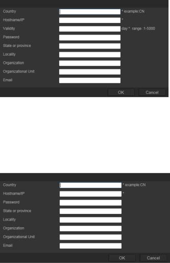
Click OK to save the settings. -Or-
To create a certificate request:
Click the Create button beside “Create Certificate Request”. Enter the country, host name/IP and the other information requested.
3.Click OK to save the settings. Download the certificate request and submit it to the trusted certificate authority for signature, such as Symantec or RSA. After receiving the signed valid certificate, upload the certificate to the device
Recording parameters
You can adjust the video and audio recording parameters to obtain the picture quality and file size best suited to your needs. Figure 5 below list the video and audio recording options you can configure for the camera.
20 |
TruVision Series 4 IP Camera Configuration Manual |
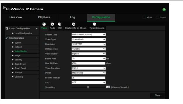
Figure 5: Video/Audio Settings menu (Video tab shown)
Tab |
Parameter descriptions |
|
|
1. Video |
Stream Type: Specifies the streaming method used. |
|
Options include: Main Stream (Normal), Sub Stream and Third stream. |
|
|
|
Video Type: Specifies the stream type you wish to record. |
|
Select Video Stream to record video stream only. Select Video&Audio to |
|
record both video and audio streams. |
|
Note: Video&Audio is only available for those camera models that support |
|
audio. |
|
|
|
Resolution: Specifies the recording resolution. A higher image resolution |
|
provides a higher image quality but also requires a higher bit rate. The |
|
resolution options listed depend on the type of camera and on whether main |
|
or sub stream is being used. |
|
Note: Resolutions can vary depending on the camera model. |
|
|
|
Bitrate Type: Specifies whether variable or fixed bit rate is used. Variable |
|
produces higher quality results suitable for video downloads and streaming. |
|
Default is Constant. |
|
|
|
Video Quality: Specifies the quality level of the image. It can be set when |
|
variable bit rate is selected. Options include: Lowest, Lower, Medium, Higher |
|
and Highest. |
|
|
|
Frame Rate: Specifies the frame rate for the selected resolution. |
|
The frame rate is the number of video frames that are shown or sent per |
|
second. |
|
Note: The maximum frame rate depends on the camera model and selected |
|
resolution. Please check the camera specifications on its datasheet. |
|
|
|
Max bit rate: Specifies the maximum allowed bit rate. To maintain image |
|
quality for high image resolution, a high bit rate must also be selected. |
|
Video Encoding: Specifies the video encoding used. |
|
|
|
Profile: Different profile options indicate different tools and technologies used |
|
in compression. Options include: High Profile, Main Profile and Basic Profile. |
|
|
TruVision Series 4 IP Camera Configuration Manual |
21 |
Tab |
|
Parameter descriptions |
|
|
|
|
|
I Frame Interval: A video compression method. It is strongly recommended |
|
|
not to change the default value 50. |
|
|
SVC: Select OFF/ON to disable/enable the SVC function. Select Auto and the |
|
|
device will automatically extract frames from the original video when the |
|
|
network bandwidth is insufficient. |
|
|
|
|
|
Smoothing: Adjust the smoothness of the stream. This setting allows for |
|
|
balancing of fluid movement with sharpness of resolution. |
|
|
|
2. |
Audio |
Audio Encoding: G.722.1, G.711ulaw, G.711alaw, MP2L2, G.726 and PCM |
|
|
are optional. |
|
|
Audio Input: Select “LineIn” or “MicIn” |
|
|
|
|
|
Input Volume: Specifies the volume from 0 to 100. |
|
|
|
|
|
Environmental Noise Filter: Set it as OFF or ON. Enable the function to |
|
|
filter background ambient noise. |
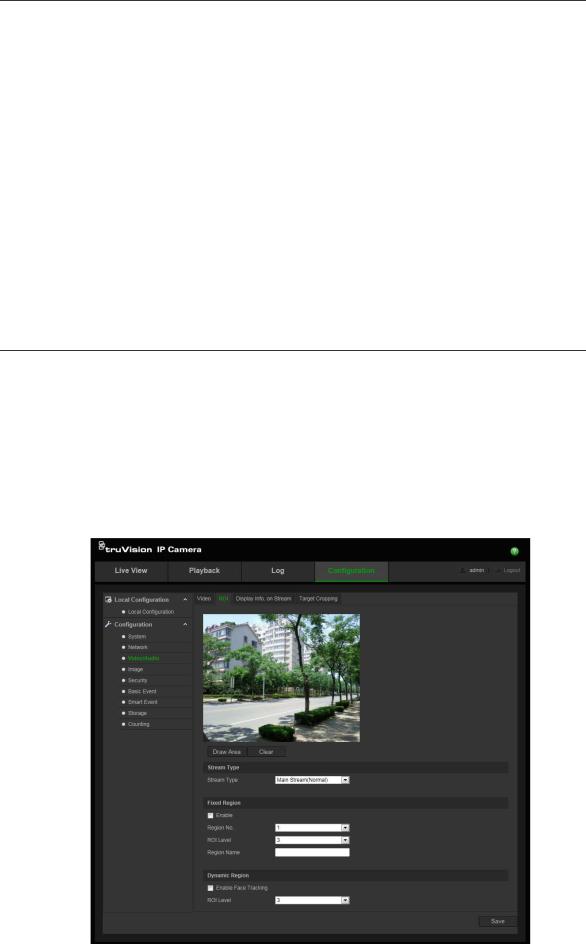
3. |
ROI |
Enable to assign more encoding resources to the region of interest to |
|
|
increase the quality of the ROI whereas the background information is less |
|
|
focused when network performance is less than optimal. |
4.Display Info. When Dual-VCA mode is enabled, the camera sends video analytics results
On Stream |
(metadata) to an NVR or other platforms to generate a VCA alarm. |
|
|
5. Target |
You can specify a target area on the live video, and then the specified video |
Cropping |
area can be displayed via the third stream in certain resolution, providing |
|
more details of the target area if needed. |
|
|
To configure ROI settings:
1. From the menu toolbar, click Configuration > Video/Audio > ROI.
22 |
TruVision Series 4 IP Camera Configuration Manual |
2.Select the desired channel from the drop-down list.
3.Draw the region of interest on the image. Up to four regions can be drawn.
4.Choose the stream type to set the ROI encoding.
5.Enable Fixed Region to manually configure the area.
Region No.: Select the region.
ROI Level: Choose the image quality enhancing level. Region Name: Set the desired region name.
6.Enable Dynamic Region for face tracking. The ROI will change, depending upon where faces are detected in the scene.
ROI Level: Choose the image quality enhancing level.
7.Click Save to save changes.
Dual-VCA (Video Content Analysis)
When Dual-VCA mode is enabled, the camera sends video analytics results (metadata) to an NVR or other platforms to generate a VCA alarm.
For example, with an Interlogix NVR (please check Interlogix website for the latest NVR models supporting this feature), you can draw a virtual line in the NVR playback window, and search the objects or people crossing this virtual line.
Note: Only cross line and intrusion detection can support dual-VCA mode.
To define Dual-VCA parameters:
1.In the Video/Audio panel, click the Display Info. On Stream tab to open its window.
2.Check the check box to enable Dual-VCA.
3.Click Save to save changes.
Target Cropping
You can specify a target area on the live video, and then the specified video area can be displayed via the third stream in certain resolution, providing more details of the target area if needed.
Note: Target cropping function varies according to different camera models.
To define Target Cropping:
1.Enter the Target Cropping settings interface.
2.Check Enable Target Cropping checkbox to enable the function.
3.Set Third Stream as the stream type.
4.Select the cropping resolution for the video display of target area. A red rectangle is displayed on the live video to mark the target area, and you can click-and-drag the rectangle to locate the target area as desired.
5.Click Save to save the settings.
TruVision Series 4 IP Camera Configuration Manual |
23 |

Video image
You may need to adjust the camera image depending on the camera model or location background in order to get the best image quality. You can adjust the brightness, contrast, saturation, hue, and sharpness of the video image. See Figure 6 below.
Use this menu to also adjust camera behavior parameters such as exposure time, iris mode, video standard, day/night mode, image flip, WDR, digital noise reduction, white balance, and indoor/outdoor mode. See Figure 6 below for more information.
Figure 6: Camera image settings menu – Display Settings tab
Parameter |
Description |
||
|
|
|
|
1. Switch Day and Night Settings |
|||
Auto-Switch |
The camera automatically switches between day and night mode. |
||
|
|
All image settings remain the same for both modes. |
|
|
|
|
|
Scheduled Switch |
The camera switches between the day and night modes according |
||
|
|
to the schedule configured (see figure below). The start and end |
|
|
|
times shown are for day mode. The other time period is for night |
|
|
|
mode. |
|
|
|
There are three tabs to configure the day/night settings: |
|
|
|
Common: The settings are identical for both day and night modes |
|
|
|
for Image Adjustment, Exposure, Day/Night Switch, Video |
|
|
|
Adjustment, and Other. |
|
|
|
Day: Configure the Backlight, White Balance and Image |
|
|
|
Enhancement settings for day mode only. |
|
|
|
Night: Configure the Backlight, White Balance and Image |
|
|
|
Enhancement settings for night mode only. |
|
|
|
|
|
24 |
|
TruVision Series 4 IP Camera Configuration Manual |
|
Loading...