


Interlogix 430085001, 430085501, 430085502, 430088001, 430088002 User Manual
...Model 94x, 97x Proximity Reader
Installation Manual

Copyright Copyright © 2008, GE Security Inc. All rights reserved.
This document may not be copied or otherwise reproduced, in whole or in part, except as specifically permitted under US and international copyright law, without the prior written consent from GE.
Document number/460157001P (January 2008).
Disclaimer THE INFORMATION IN THIS DOCUMENT IS SUBJECT TO CHANGE WITHOUT NOTICE. GE ASSUMES NO RESPONSIBILITY FOR INACCURACIES OR OMISSIONS AND SPECIFICALLY DISCLAIMS ANY LIABILITIES, LOSSES, OR RISKS, PERSONAL OR OTHERWISE, INCURRED AS A CONSEQUENCE, DIRECTLY OR INDIRECTLY, OF THE USE OR APPLICATION OF ANY OF THE CONTENTS OF THIS DOCUMENT. FOR THE LATEST DOCUMENTATION, CONTACT YOUR LOCAL SUPPLIER OR VISIT US ONLINE AT WWW.GESECURITY.COM.
This publication may contain examples of screen captures and reports used in daily operations. Examples may include fictitious names of individuals and companies. Any similarity to names and addresses of actual businesses or persons is entirely coincidental.
Trademarks GE and the GE monogram are registered trademarks of General Electric. and patents Model 94x/97x Proximity Reader product and logo are trademarks of
GE Security.
Other trade names used in this document may be trademarks or registered trademarks of the manufacturers or vendors of the respective products.
Intended use Use this product only for the purpose it was designed for; refer to the data sheet and user documentation. For the latest product information, contact your local supplier or visit us online at www.gesecurity.com.
FCC This equipment has been tested and found to comply with the limits for a compliance Class A digital device, pursuant to part 15 of the FCC Rules. These limits are
designed to provide reasonable protection against harmful interference when the equipment is operated in a commercial environment. This equipment generates, uses, and can radiate radio frequency energy and, if not installed and used in accordance with the instruction manual, may cause harmful interference to radio communications.
You are cautioned that any changes or modifications not expressly approved by the party responsible for compliance could void the user's authority to operate the equipment.
Regulatory

i
Contents
Introduction . . . . . . . . . . . . . . . . . . . . . . . . . . . . . . . . . . . . . . . . . . . . . . . . . . 1 Safety. . . . . . . . . . . . . . . . . . . . . . . . . . . . . . . . . . . . . . . . . . . . . . . . . . . . . . . . 2
Radio interference . . . . . . . . . . . . . . . . . . . . . . . . . . . . . . . . . . . . . . . . . . . . . .2 Electrostatic discharge (ESD) precaution . . . . . . . . . . . . . . . . . . . . . . . . .2
Product features . . . . . . . . . . . . . . . . . . . . . . . . . . . . . . . . . . . . . . . . . . . . . . 3 System requirements. . . . . . . . . . . . . . . . . . . . . . . . . . . . . . . . . . . . . . . . . . 4 Technical specifications . . . . . . . . . . . . . . . . . . . . . . . . . . . . . . . . . . . . . . . 5 Parts list . . . . . . . . . . . . . . . . . . . . . . . . . . . . . . . . . . . . . . . . . . . . . . . . . . . . . 6 Installation overview . . . . . . . . . . . . . . . . . . . . . . . . . . . . . . . . . . . . . . . . . . 7 Mounting the reader . . . . . . . . . . . . . . . . . . . . . . . . . . . . . . . . . . . . . . . . . . 8
Back-to-back readers. . . . . . . . . . . . . . . . . . . . . . . . . . . . . . . . . . . . . . . . . . .9 External tamper feature . . . . . . . . . . . . . . . . . . . . . . . . . . . . . . . . . . . . . . . .9 Mounting diagrams. . . . . . . . . . . . . . . . . . . . . . . . . . . . . . . . . . . . . . . . . . . .10
Configuring the reader . . . . . . . . . . . . . . . . . . . . . . . . . . . . . . . . . . . . . . . 20
Switch settings . . . . . . . . . . . . . . . . . . . . . . . . . . . . . . . . . . . . . . . . . . . . . . . .20 Selecting reader power level . . . . . . . . . . . . . . . . . . . . . . . . . . . . . . . . . . .20 Selecting operating mode. . . . . . . . . . . . . . . . . . . . . . . . . . . . . . . . . . . . . .26 Selecting beeper sound level . . . . . . . . . . . . . . . . . . . . . . . . . . . . . . . . . . .27
Connecting the reader. . . . . . . . . . . . . . . . . . . . . . . . . . . . . . . . . . . . . . . . 28
Pinouts . . . . . . . . . . . . . . . . . . . . . . . . . . . . . . . . . . . . . . . . . . . . . . . . . . . . . . .28 Wiring diagrams. . . . . . . . . . . . . . . . . . . . . . . . . . . . . . . . . . . . . . . . . . . . . . .29
Testing the reader . . . . . . . . . . . . . . . . . . . . . . . . . . . . . . . . . . . . . . . . . . . 36 Troubleshooting the reader . . . . . . . . . . . . . . . . . . . . . . . . . . . . . . . . . . . 38
All installations . . . . . . . . . . . . . . . . . . . . . . . . . . . . . . . . . . . . . . . . . . . . . . . .38 Unsupervised modes only . . . . . . . . . . . . . . . . . . . . . . . . . . . . . . . . . . . . .41 Supervised modes only . . . . . . . . . . . . . . . . . . . . . . . . . . . . . . . . . . . . . . . .41
Regulatory approvals . . . . . . . . . . . . . . . . . . . . . . . . . . . . . . . . . . . . . . . . 44
UL . . . . . . . . . . . . . . . . . . . . . . . . . . . . . . . . . . . . . . . . . . . . . . . . . . . . . . . . . . . .44 CE . . . . . . . . . . . . . . . . . . . . . . . . . . . . . . . . . . . . . . . . . . . . . . . . . . . . . . . . . . . .45
iiModel 94x/97x Proximity Reader Installation Manual
Figures |
|
|
Figure 1. |
Recommended Additional Mounting Instructions |
|
|
for External Tamper Switch Activation.............................. |
11 |
Figure 2. |
Model 940 Reader - Gang Box Mounting ......................... |
12 |
Figure 3. |
Model 940 Reader - Direct Wall Mounting....................... |
13 |
Figure 4. |
Model 941 Reader - Gang Box Mounting ......................... |
14 |
Figure 5. |
Model 941 Reader - Direct Wall Mounting....................... |
15 |
Figure 6. |
Model 970/972 Reader - Gang Box Mounting ............... |
16 |
Figure 7. |
Model 970/972 Reader - Direct Wall Mounting............. |
17 |
Figure 8. |
Model 971/973 Reader - Gang Box Mounting ............... |
18 |
Figure 9. |
Model 971/973 Reader - Direct Wall Mounting............. |
19 |
Figure 10. |
Model 94x/97x Reader, J1 Connector and DIP |
|
|
Switch Locations (PCB Assembly P/N 100079002 |
|
|
manufactured 12/02 or later)................................................ |
22 |
Figure 11. |
(PCB Assembly P/N 100079001 manufactured | |
|
|
prior to 12/02)................................................................................ |
23 |
Figure 12. |
Wiring Diagram, Model 94x/97x |
|
|
Supervised F/2F Mode............................................................... |
30 |
Figure 13. |
Wiring Diagram, Model 94x/97x |
|
|
Unsupervised F/2F Mode ......................................................... |
32 |
Figure 14. |
Wiring Diagram, Model 94x/97x |
|
|
Unsupervised Wiegand Mode .............................................. |
34 |
Figure 15. |
Typical Installation (Internal to the microcontroller) |
|
|
Using Shielded Cable/Drain Wire......................................... |
46 |
Figure 16. |
Typical Installation (External to the microcontroller) |
|
|
Using Shielded Cable/Drain Wire......................................... |
46 |

Introduction  1
1
Introduction
This manual is an installation guide for the GE Models 940, 941, 970, 971, 972, and 973 proximity readers. Throughout this guide, the abbreviation 94x represents reader models 940 and 941. The abbreviation 97x represents reader models 970, 971, 972, and 973.
The 94x and 97x readers while similar in functionality offer a variety of features making them suitable for different applications. The 94x and 97x readers are designed to mount on standard U.S. gang boxes. The 94x readers are single-gang box size. The 97x readers are sized for larger dual gang box installation, offer greater badge read range, and a keypad option.
Models 940 and 970 give the greatest all-around badge read range for their respective sizes, making them ideal for most installations.
Models 941 and 971 are tuned for installation on metal mounting plates. The standard metal mounting plate shields the reader from the effects of a metal wall, which would otherwise dramatically reduce the read range. The optional back-to-back metal mounting plate shields the reader from the effects of a metal wall and makes the reader unidirectional; ideal for direct back-to-back reader installations.
Models 972 and 973 are dual gang size readers, identical to the 970 and 971 respectively, except for their built-in twelve-position keypad. This feature makes these readers ideal for installations requiring keypad PIN entry in addition to a valid badge read.

2Model 94x/97x Proximity Reader Installation Manual
Safety
Radio interference
WARNING: This is an FCC Class A product. In a domestic environment, this product may cause radio interference, in which case, the user may be required to take adequate measures.
Electrostatic discharge (ESD) precaution
WARNING: Circuit board components are vulnerable to damage by electrostatic discharge (ESD). ESD can cause immediate or subtle damage to sensitive electronic parts. An electrostatic charge can build up on the human body and then discharge when you touch a board. A discharge can be produced when walking across a carpet and touching a board, for example. Before handling any board, make sure you dissipate your body’s charge by touching ground. This discharges any static electricity build-up.

Product features  3
3
Product features
The GE Model 94x/97x Reader offers:
•Intelligent bidirectional communication between the reader and microcontroller, which can be accomplished up to 5,500 feet.
•The ability to read all ISO ProxLiteTM, ProxLite, and Entrée badges and key tags.
•Field changeable DIP switches allow all 94x and 97x readers to operate in one of four distinct operating modes: Wiegand (4001), F/2F, Supervised, and Silent Supervised.
•Rugged, weather-resistant, molded ABS construction with integral backplate.
•Standard 12V operation.
•A clear, logical user interface with three LEDs and a switch selectable beeper with volume control.
•Built-in tamper alarm also detects removal from wall.
•External tamper alarm option.
•Tactile keypad (Models 972 and 973 only) for Personal Identification Number (PIN) input.

4Model 94x/97x Proximity Reader Installation Manual
System requirements
Host software |
• |
Secure Perfect® Edition 3.0 or later |
|
• |
Picture Perfect™ 1.7 or later |
Microcontrollers |
• |
Micro/2 |
|
• |
Micro/4 |
|
• Micro/5-PX with 2RP or 8RP |
|
|
• Micro/5-PXN with 2RP or 8RP |
|
|
• M5PXNplus with 2RP or 8RP |
|
|
• |
Micro/PX-2000 |
|
• Micro/PXN-2000 |
|
|
• M2000PXNplus |
|
|
• M3000PXNplus with 2RP or 8RP |
|
|
|
|
Microcontroller |
• |
For Micro/2 and Micro/4: |
firmware |
|
Secure Perfect: Version 5 or later |
|
|
Picture Perfect: Version 1.7.0 or later |
|
• For Micro/5-PX, Micro/5-PXN, Micro/PX-2000 |
|
|
|
and Micro/PXN-2000: |
|
|
Secure Perfect: 3.1.0.6 or later |
|
|
Picture Perfect: 1.7.0 or later |
|
|
|
Badge and keytag |
• |
ISO ProxLite |
formats |
• |
ProxLite |
|
• |
Entrée |
|
• |
Proximity Perfect |
Note: Proximity Perfect cards are obsolete however they are supported by the Model 94x/97x readers.

Technical specifications  5
5
Technical specifications
For UL compliant installation notes, refer to “UL” on page 44.
Operating |
-31 F (-35 C) to +151 F (+66 C) |
temperature range |
|
|
|
Relative humidity |
5% to 95% (non-condensing) |
|
|
Physical dimensions |
(HxWxD) |
Model 94x |
4.75" (121 mm) x 2.9" (74 mm) x 0.90" (23 mm) |
Model 97x |
4.75" (121 mm) x 5.5" (140 mm) x 0.90" (23 mm) |
|
|
Index of protection |
IP55 |
|
|
Color |
Light gray and black |
|
|
Power supply |
Nominal 12VDC, 75mA, 150mA or 200mA |
|
dependent on the power setting selected. |
|
See Table 1 “Power level switch settings,” on page 24 |
|
|
Cable specifications |
Belden 8725 or equivalent, 20 AWG minimum, |
|
shielded pairs |
|
|
Maximum cabling |
The maximum cable distance between the reader |
distancea |
and the microcontroller is influenced by a number of |
|
factors including wire gauge and reader power level |
|
setting. See Table 3 “Cable distances,” on page 25. |
|
|
Read range |
Determined by the reader’s power level setting and |
|
other environmental conditions. See Table 2 “Read |
|
range by model number,” on page 24. |
|
|
Pinouts |
The reader is supplied with a ten-wire cable. On one |
|
end is a keyed connector that mates with the J1 |
|
connector on the back of the reader. The other ends |
|
are stripped ready for connection to the field wiring |
|
using a terminal block or in-line splice connectors. |
|
|
a.The reader will work well with unshielded cable in most environments. No company, including GE, can guarantee that data will be reliably transmitted over long distances on unshielded cable in every installation.

6Model 94x/97x Proximity Reader Installation Manual
Parts list
•Model 940 Reader (single-gang) gray
•Model 940 Reader (single-gang) black
•Model 941 Reader (single-gang metal mount) gray
•Model 941 Reader (single-gang metal-mount) black
•Model 970 Reader (dual-gang) gray
•Model 970 Reader (dual-gang) black
•Model 971 Reader (dual-gang metal-mount) gray
•Model 971 Reader (dual-gang metal-mount) black
•Model 972 Reader (dual-gang with keypad) gray
•Model 972 Reader (dual-gang with keypad) black
•Model 973 Reader (dual-gang metal mount w/keypad) gray
•Model 973 Reader (dual-gang metal mount w/keypad) black
•Optional Tamper Key Tool
•94x Plastic Backplate (gray)
•94x Plastic Backplate (black)
•97x Plastic Backplate (gray)
•97x Plastic Backplate (black)
•Standard 941 Metal Mounting Plate (gray)
•Standard 941 Metal Mounting Plate (black)
•Standard 971/973 Metal Mounting Plate (gray)
•Standard 971/973 Metal Mounting Plate (black)
•Optional Back-to-Back 941 Metal Mounting Plate (gray)
•Optional Back-to-Back 971/973 Metal Mounting Plate (black)
•94x Weather-resistant Gasket
•97x Weather-resistant Gasket
•Reader Cable
Refer to the GE Product Catalog for part numbers and ordering information.
Installation overview  7
7
Installation overview
The following steps are general instructions for installing the 94x/ 97x reader. Each step is explained in further detail in the sections that follow.
1.Mount the reader backplate.
Refer to “Mounting the reader” on page 8.
2.Configure the reader.
Refer to “Configuring the reader” on page 20.
3.Connect the reader.
Refer to “Connecting the reader” on page 28.
4.Test the reader.
Refer to “Testing the reader” on page 36.

8Model 94x/97x Proximity Reader Installation Manual
Mounting the reader
The reader comes with a backplate suitable for mounting directly onto standard U.S. electrical gang boxes (Model 94x onto singlegang box and Model 97x onto dual-gang box). The reader may also be mounted directly onto a hollow wall.
Important:
•Readers should not be mounted within three feet of a computer terminal. Some terminals radiate electrical noise that may reduce the effective maximum read range.
•Never mount Models 940, 970 or 972 on or near metal. Metal effects the tuning of the reader and may severely degrade its performance, decreasing read range and increasing current draw.
•Models 941, 971 and 973 are factory tuned to work with a metal back and must be mounted with the metal mounting plate to operate correctly.
•A gasket is supplied with the reader to form a weatherresistant seal between the mounting surface and the inside of the reader for outdoor installations. The gasket should be located on the inside surface of the reader’s plastic backplate. For outdoor installations, where the reader is mounted in direct exposure to weather, a bead of silicone caulking should be applied between the reader and the wall to prevent water from entering the back of the reader.

Mounting the reader  9
9
Back-to-back readers
Models 941, 971 and 973 Readers are suitable for back-to-back installation (to provide in/out access control). Using the standard metal mounting plates, the two readers should be mounted with their centers offset by at least 10 inches to provide interferencefree operation. Using the optional back-to-back metal mounting plates allows the two readers to be mounted directly opposite each other on a 4-inch thick wall.
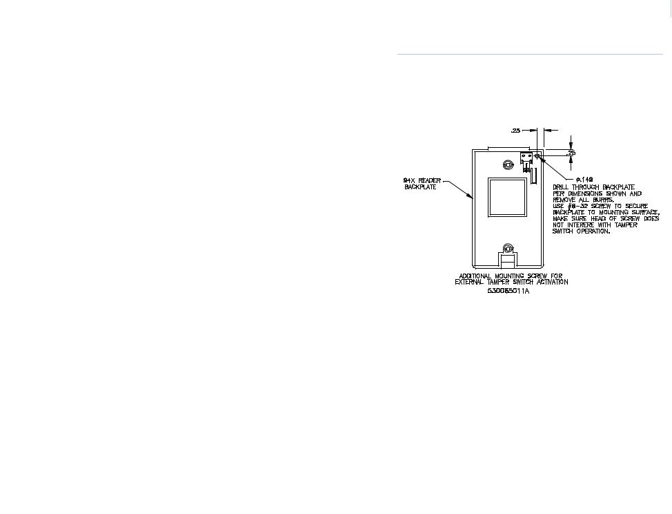
External tamper feature
The Model 94x/97x Readers are also equipped with an external tamper feature. This feature can be activated by removing the key on the backplate prior to mounting.
Model 94x only: Apply the mounting method as shown in
Figure 1, Recommended Additional Mounting Instructions for External Tamper Switch Activation to mounting instructions in Figure 2, "Model 940 Reader - Gang Box Mounting" Figure 3, "Model 940 Reader - Direct Wall Mounting" Figure 4, "Model 941 Reader - Gang Box Mounting" and Figure 5, "Model 941 Reader - Direct Wall Mounting" if you are using the external tamper feature.
Note: In order for this feature to work properly, the reader mounting surface must be flush with the backplate.

10Model 94x/97x Proximity Reader Installation Manual
Mounting diagrams
The figures listed below begin on the next page. Refer to the appropriate figure for the type of reader you are mounting.
•Figure 1, Recommended Additional Mounting Instructions for External Tamper Switch Activation
•Figure 2, “Model 940 Reader - Gang Box Mounting,” on page 12.
•Figure 3, “Model 940 Reader - Direct Wall Mounting,” on page 13.
•Figure 4, “Model 941 Reader - Gang Box Mounting,” on page 14.
•Figure 5, “Model 941 Reader - Direct Wall Mounting,” on page 15.
•Figure 6, “Model 970/972 Reader - Gang Box Mounting,” on page 16.
•Figure 7, “Model 970/972 Reader - Direct Wall Mounting,” on page 17.
•Figure 8, “Model 971/973 Reader - Gang Box Mounting,” on page 18.
•Figure 9, “Model 971/973 Reader - Direct Wall Mounting,” on page 19.
Mounting the reader  11
11
Figure 1. Recommended Additional Mounting Instructions for External Tamper Switch Activation

12Model 94x/97x Proximity Reader Installation Manual
Figure 2. Model 940 Reader - Gang Box Mounting
 Loading...