


Contents
Safety....................................................................... |
E2 |
|
Copyright ................................................................ |
E3 |
|
Glossary................................................................... |
E4 |
|
Reference ................................................................ |
E5 |
~ E6 |
STB Connections..................................................... |
E7 |
~ E10 |
Remote Control Unit ................................................ |
E11 ~ E12 |
|
Guide of Functions .................................................. |
E13 ~ E14 |
|
Guide of Main Menu ................................................ |
E15 ~ E41 |
|
Motorised System.................................................... |
E42 ~ E45 |
|
Troubleshooting Guide ............................................ |
E46 |
|
Menu Map................................................................ |
E47 ~ E48 |
|
Specification ............................................................ |
E49 ~ E50 |
|
E1
Safety
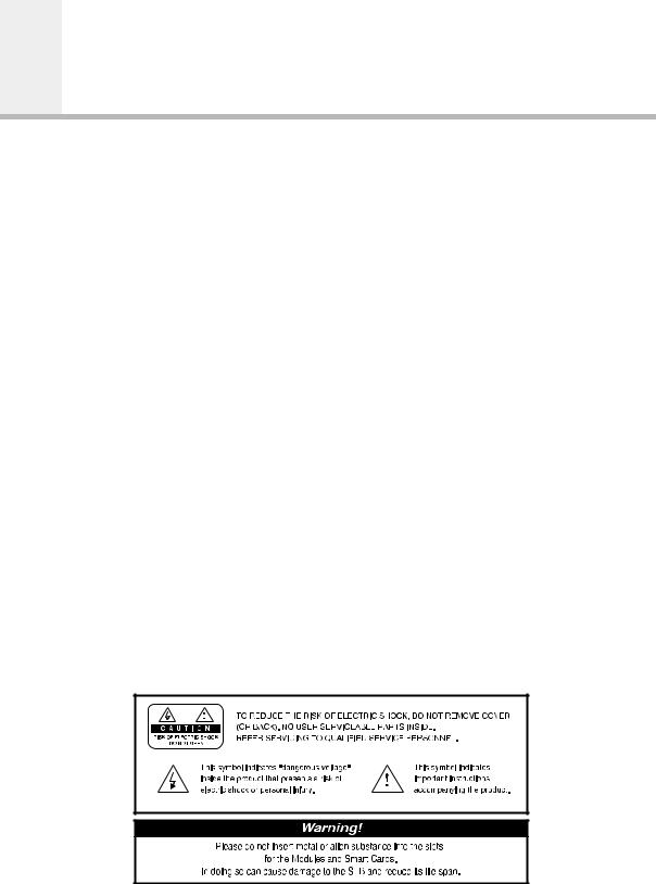
This STB has been manufactured to satisfy the international safety standards. Please read the following safety precautions carefully.
MAINS SUPPLY : 190 - 250 V AC 50/60 Hz
OVERLOADING : Do not overload a wall outlet, extension cord or adapter as this may result
|
in fire electric shock. |
LIQUIDS |
: The STB shall not be exposed to dripping or splashing and that no |
|
objects filled with liquids, such as base, shall be placed on the apparatus. |
CLEANING |
: Disconnect the STB from the wall outlet before cleaning. |
|
Use a light damp cloth(no solvents) to dust the STB. |
VENTILATION : The slots on top of the STB must be left uncovered to allow proper airflow to the unit.
Do not stand the STB on soft furnishings or carpets.
Do not expose the STB to direct sunlight or do not place it near a heater. Do not stack electronic equipments on top of the STB.
ATTACHMENTS : Do not use any unrecommended attachments as these may cause hazard or damage the STB.
CONNECTION TO THE SATELLITE DISH LNB
:Disconnect the STB from the mains before connecting or disconnecting the cable from the satellite dish.
FAILURE TO DO SO CAN DAMAGE THE LNB.
CONNECTION TO THE TV
:Disconnect the STB from the mains before connecting or disconnecting the cable from the satellite dish.
FAILURE TO DO SO CAN DAMAGE THE TV.
EARTHING : The LNB cable MUST BE EARTHED.
The earthing system must comply with SABS 061.
LOCATION : Place the STB indoor in order not to expose to lightening, rain or sunlight.
E2

Copyright
 Copyright


•VIACCESSTM is a trademark of France Telecom.
•CryptoWorks(TM) is a trademark of Philips Electronics N.V.
•Irdeto is a trademark of Mindport BV.
•Nagravision is a registered trademark of Kudelski S.A.
•Conax is a trademark of Telenor Conax AS.
•“Dolby” and the double-D symbol are trademarks of Dolby Laboratories.
 Warning


HUMAX cannot be held responsible for any kind of problems caused by the use of unofficial software. The use of software versions other than HUMAX official software will void the manufacturer’s warranty.
It is advised that only the formal software released from HUMAX should be used in all HUMAX product range.
Caution
To watch Pay Per View programmes, be sure to inform your STB dealer of the STB’s and Smart card’s serial numbers. So that they can pair your STB with your Smart card. Otherwise, you cannot watch the programmes because they are scrambled.
Note
When the changed Network Information is sent, Nagravision realizes that the appropriate satellite/cable service information has been changed. And it will re-organize the service information based on the sent Network Information. The message “Network Information updated...” appears on the screen. It is automatically done when changing NIT.
The manufacturer can’t change it because it is provided by Nagravision.
When the user watches it, the message may suddenly appear during AV playback and simultaneously updating will proceed. (This happens about once a year.)
Since this is not an error in operating, do not turn off the power.
•Information for TV-Cabo subscriber
When user searchs channels, the channel numbers from 001 to 100 are defined automatically for Nagravision by service provider.
Other channels have the number from 101 in sequence as the receiver searchs the signal.
• Specifications are for NACI-5700 models.
GB3

Glossary
 Glossary


•Antenna
A device that collects and radiates electromagnetic waves. Includes a satellite dish and abroadband antenna.
•Forward Error Correction(FEC)
A system of error control for data transmission.
•Frequency
The number of cycles or events per one second, which is expressed in the unit of Hertz(Hz).
•Intermediate Frequency(IF)
A frequency to which a carrier frequency is shifted as an intermediate step in transmission or reception.
•Low Noise Block(LNB) Downconverter
A low noise microwave amplifier and converter which downconverts a range of frequencies to IF range.
•Packet Identifier(PID)
A set of numbers that idenitifies transport stream packets containing data from a single data stream.
•Polarisation
Characteristic of an electromagnetic wave determined by the orientation of the electricfield vector.
•Quaternary Phase Shift Keying(QPSK)
Phase-shift keying in which four different phase angles are used.
•Service
A channel to which a decoder or TV is tuned.
•Transponder
An automatic device that receives, amplifies and retransmits a signal on a different frequency.
E4
Reference
 1. Connect DiSEqC 1.0


All our receivers are designed to be DiSEqC 1.0 compatible. This allows multiple antennas to be connected to the STB simultaneously.
If you have two or more fixed antennas or LNBs, you can use a DiSEqC 1.0 switch.
1.Connect the coaxial cable from the first LNB to the LNB 1 or LNB A input connector of the DiSEqC switch.
2.Connect the coaxial cable from the second LNB to the LNB 2 or LNB B input connector of the DiSEqC switch.
3.Do the same for other LNBs.
4.Connect one end of a Coaxial cable to the RF output connector of the DiSEqC switch and the other end to the LNB IN socket on the STB.
 2. Connect DiSEqC 1.2


Please refer to page GB42.
The Locking Time might take longer than expected during the initial boot if the motorised system is set “enable” mode.
 3. Connect a Satellite antenna


To the digital receiver, you can connect either a single satellite antenna directly or through converter box several antennas or LNB of multi-feed equipment.
You can connect a further Sat-receiver(for example analogue), with the receiver of common antenna equipment that has satellite signals.
• Connect an antenna cable through converter boxes
1.When you assemble several antenna or a multi-feed equipment that has several LNB (or LNB with several exits), connect each cable from the antenna to a converter box.
2.Connect the output of converter box to “LNB IN”, as in example displayed.
3.When you use a converter box of 0/12V-steerage, connect it to the output “0/12V” additionally.
For converter boxes of 22KHzor DiSEqC-steerage, you can skip this point because the steerage signal occurs through the antenna cable.
 4. Loop Through


If you have another analogue or digital STB and you wish to use the same LNB then you can connect it via the loop through. Connect one end of a Coaxial cable to the LNB OUT on the STB and connect the other end to the LNB IN on your second STB.
GB5
 5. Connect a S/PDIF Fiber-Optic cable


If you are watching a programme with a Dolby Digital soundtrack(see page E14) you can enjoy the higher quality sound of the Dolby Digital audio by connecting the STB to an external Dolby Digital television or amplifier. Do this by connecting the optical S/PDIF output of the STB to the optical S/PDIF input of the external Dolby Digital product (television, amplifier,.....).
 6. Software Upgrade


HUMAX digital set-top box is a highly sophisticated product - incorporating one of the best software applications.
Whenever a problem is found with this software or, in fact, extra functions or enhanced applications are added, the software in the equipment has to be upgraded.
In order to maintain proper performance of the product, it is essential to have the most up to date software. The latest news and release of software versions may be found at HUMAX website - http://www.humaxdigital.com.
It is recommended that users register to HCSA(HUMAX Customer Service Area) and periodically check for the availability of software upgrade.
There are three methods to upgrade the software:
(a)set-top box to set-top box download(copies the software of the main unit into slave unit);
(b)pc to set-top box download(downloads the software directly from pc to the model requiring upgrade);
(c)OTA over-the-air(downloads the software where the manufacturer reserves the right to decide when and where to release through satellite system).
Over The Air(OTA) is simply another alternative for downloading software versions. However, the manufacturer reserves the right to decide when and where this software upgrade can take place by "beaming" latest software versions over the air via satellite systems. Note that OTA is only limited to certain geographical regions mainly due to different satellites having different footprints(area where the signal can be received).
SUSS(TM) is an official trademark and logo for HUMAX loader software to perform OTA. The software upgrade via satellite system will only occur under the following circumstances:
1)the equipment should have appropriate loader software;
2)the manufacturer decides to release software downloading via a designated satellite system;
3)the equipment must be "tuned" properly to the same satellite that the manufacturer uses.
• Note : CRCI-5500 complies with the OTA type of CryptoWorks.
E6
STB Connections
 Front Panel


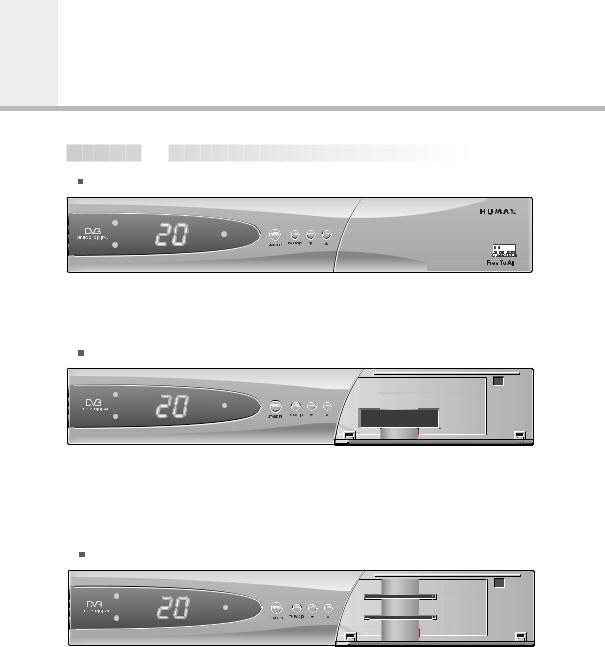
F1-5000 Free-To-Air
F1-5000
CI-5100 2 Slot Common Interface
VA-5200 2 Smart card
• Warning
To install the unauthorized CAM into CI slot can cause the wrong operation. Do not reinstall the CAM of the already embedded CAS to prevent the wrong operation.
E7
 Front Panel


VACI-5300, CRCI-5500, NACI-5700 2 Slot Common Interface, 1 Smart card
8 |
9 |
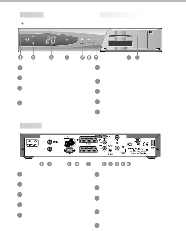
1 TV LED(AMBER) |
5 STANDBY |
The LED lights on in TV mode.
2 RADIO LED(GREEN)
The LED lights on in RADIO mode.
3 DISPLAY
Shows service number, error messages, RCU commands and time in Standby mode.
Press to switch between Operation and Standby modes.
6 TV/RADIO
Press to switch between TV and Radio modes.
7  ,
, 
Use to change services down/up.
4 STANDBY LED(RED) |
8 |
SLOT |
Indicates that the STB is under standby. |
|
For a two CA Module with a smart card. |
|
|
|
|
9 |
SMART CARD |
|
|
For a Smart cards. |
 Rear Panel


|
|
|
|
|
|
|
|
|
|
|
|
|
|
|
|
|
|
|
|
|
|
|
|
|
|
|
|
|
|
|
|
|
|
|
|
|
|
|
|
|
|
|
|
|
|
|
|
|
|
|
|
|
|
|
|
|
|
|
|
|
|
|
|
|
|
|
|
|
|
|
|
|
|
|
|
|
|
|
|
|
|
|
|
|
|
|
|
|
|
|
|
|
|
|
|
|
|
|
|
|
|
|
|
|
|
|
|
|
|
|
|
|
|
|
|
|
|
|
|
|
|
|
|
|
|
|
|
|
|
|
|
|
|
|
|
|
|
|
|
|
|
|
|
|
|
|
|
|
|
|
|
|
|
|
|
|
|
|
|
|
|
|
|
|
|
|
|
|
|
|
|
|
|
|
|
|
|
|
|
|
|
|
|
|
|
|
|
|
|
|
|
|
|
|
|
|
|
|
|
|
|
|
|
|
|
|
|
|
|
|
|
|
|
|
|
|
|
|
|
|
|
|
|
|
|
|
|
|
|
|
|
|
|
|
|
|
|
|
|
1 LNB IN |
|
|
|
|
|
|
|
|
|
|
|
|
|
|
|
|
|
|
|
|
|
|
|
|
|
|
|
||
|
|
|
|
|
|
|
|
|
|
|
|
|
|
|
|
|
|
|
|
|
|
|
|
|
|
|
|||
|
|
|
|
|
|
|
|
|
6 AUDIO/VIDEO OUTPUT |
|
|
||||||||||||||||||
Use to connect an antenna.
2 LNB OUT
Use it when connecting to another STB.
3 RS-232C
Use it when connecting to your PC.
4 TV SCART
For the audio/video input of the TV.
5 VCR SCART
For the VCR.
Audio/video signal from your STB to VCR or TV.
7 0/12V OUT
For an external LNB switch.
8 RF OUTPUT
Use to connect a RF signal from your STB to RF(ANT) input jack on your TV.
9 RF INPUT
Use to connect a general Aerial Antenna and CABLE jacks to a RF input jack on the STB.
10 S/PDIF
Output for connection to a digital amplifier.
E8
STB Connections
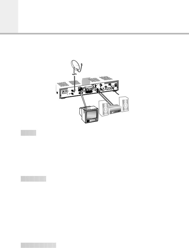
There are several ways of connecting the STB to your existing Audio/TV system. We recommend using one of the following set-up for best results:
 TV only


1.Connect one end of a 21-pin SCART cable to the TV SCART connector on the STB and the other end to a SCART socket on your TV.
2.Connect one end of a RF lead to the RF OUT connector on the STB and the other end to the RF IN connector on your TV.
3.Connect your TV antenna to the RF IN connector on the STB for receiving terrestrial channels.
4.Connect the coaxial cable from the LNB to the LNB IN socket on the STB.
 TV with VCR


1.Connect one end of a 21-pin SCART cable to the TV SCART connector on the STB and the other end to a SCART socket on your TV.
2.Connect one end of a 21-pin SCART cable to the VCR SCART connector on the STB and the other end to a SCART socket on your VCR.
3.Connect one end of a RF lead to the RF OUT connector on the STB and the other end to the RF IN connector on your VCR.
4.Connect one end of a RF lead to the RF OUT connector on your VCR and the other end to the RF IN connector on your TV.
5.Connect your TV antenna to the RF IN connector on the STB for receiving terrestrial channels.
6.Connect the coaxial cable from the LNB to the LNB IN socket on the STB.
 With Hi-Fi System


1.Connect an RCA/Cinch stereo cable from the AUDIO L, R sockets on the back of the STB to the LINE, AUX, SPARE OR EXTRA input sockets on your Hi-Fi system.
E9
 TV with VCR and Motorised System(DiSEqC 1.2)


1.Connect one end of a 21-pin SCART cable to the TV SCART connector on the STB and the other end to a SCART socket on your TV.
2.Connect one end of a 21-pin SCART cable to the VCR SCART connector on the STB and the other end to a SCART socket on your VCR.
3.Connect one end of a RF lead to the RF OUT connector on your VCR and the other end to the RF IN connector on your TV.
4.Connect one end of a RF lead to the RF IN connector on your VCR and the other end to the RF OUT connector on the STB.
5.Connect the coaxial cable from the LNB of your motorised system to the LNB IN socket on the STB.
6.Connect your TV antenna to the RF IN connector on the STB for receiving terrestrial channels.
7.Connect the coaxial cable from the LNB to the LNB connector on the DiSEqC 1.2 motor.
E10
Remote Control Unit
E11

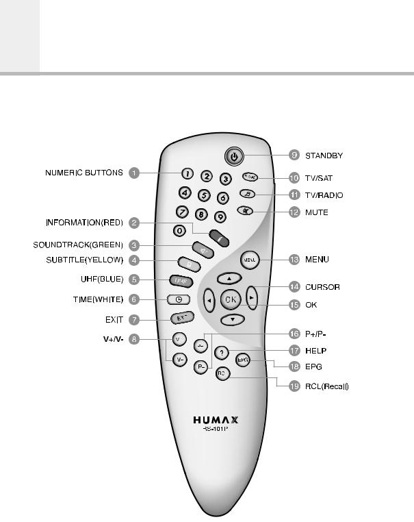
1NUMERIC BUTTONS
Press to select a service, enter your
PIN code or numeric on the menu.
2INFORMATION(RED)
Press to display the programme information box on the screen. And this button functions same as the RED button on the menus.
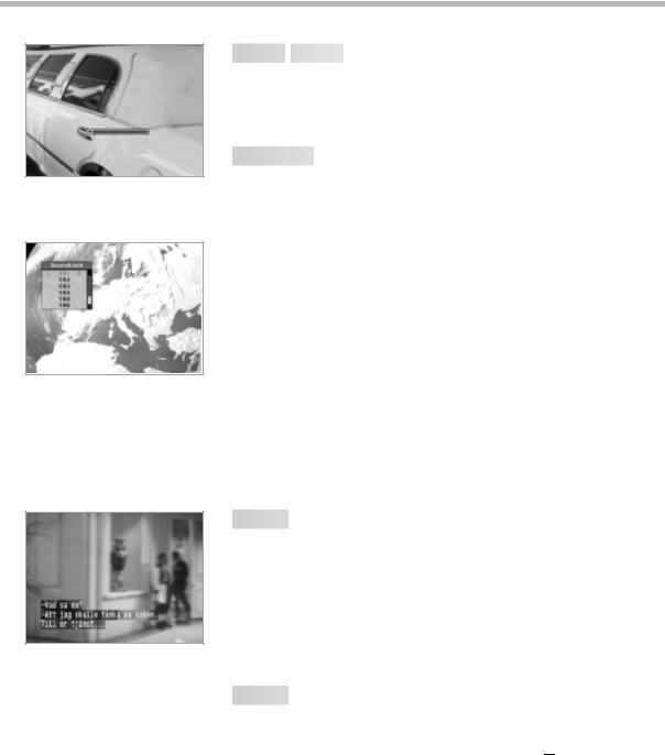
3SOUNDTRACK(GREEN)
Press to display the soundtrack list for the current service. And this button functions same as the GREEN button on the menus.
4SUBTITLE(YELLOW)
Press to display the subtitle language list for the current service. And this button functions same as the YELLOW button on the menus.
5UHF(BLUE)
Press to set the UHF menu.
This button functions same as the BLUE button on the menus.
6TIME(WHITE)
Press to display the current time on the screen. Press to reserve services on the Informaion box or EPG.
And this button functions same as the WHITE button on the menus.
7EXIT
Press to return to the previous menu and screen.
8V+/V-
Volume up/down buttons.
Press to increase or decrease the volume.
9STANDBY
Press to switch between Operation and
Standby modes.
10TV/SAT
Press to select the TV/SAT mode.
11TV/RADIO
Press to switch between TV and Radio modes.
12MUTE
Press to temporarily cut off the sound.
13MENU
Press to display the Main Menu on the screen or return to the screen from
a sub menu screen.
14CURSOR
Press to move the highlight bar for selecting options on the menus.
And this button is used to change services
(up/down) and increase or decrease the audio volume.
15OK
Press to display the service list. This button is used to select the item on the menus.
16P+/P-
Programme up/down buttons.
Press to tune to the next or previous service. Press to move up or down pages on the menus.
17HELP
Press to display the help box on the screen.
18EPG
Electronic Programme Guide button displays the TV/Radio programme guide.
19RCL(Recall)
Press to select the service that was previously viewed.
• Please note : The design of Remote Control Unit may be changed without notice in advance.
E12
Guide of Functions

 Information
 Box(I-Plate)


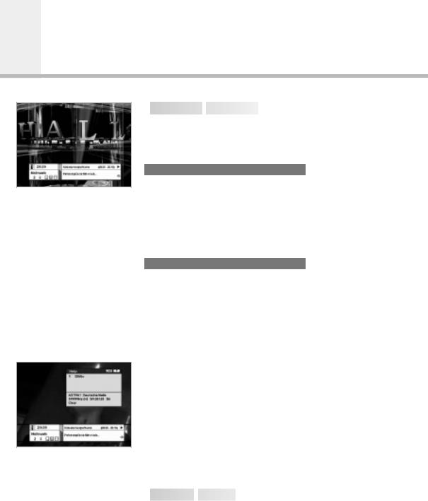
The details of service part and event part are automatically displayed on the I-Plate when pressing the i button(  ) or changing services.
I-Plate is divided into service part and event part.
SERVICE-PART(Left side of the box)
SERVICE PART consists of the following items:
•I-Plate icon, Current time and Dolby Digital symbol
•Service name, Service number,  icons
icons
•Subtitle, Teletext, Scrambling service symbol
(These are automatically displayed when the broadcasting station provides appropriate information.)
•Signal level and Signal quality bar
EVENT-PART(Right side of the box)
EVENT PART consists of the following items:
•Event name, Event duration time
•Description text of event, State of reserved event
Event Part shows the current and next event information.
 button : Use to move from the current event information to the next event information.
 button : Use to move from the next event information to the current event information.
When the HELP(  )button is pressed under I-Plate display and there are no detailed event informations in the I-Plate,
the Help window will appear on the screen.
The Help window shows the current Network information, including: Satellite Name, Frequency, Polarisation, Symbol Rate, FEC...
The detailed information for the event can be displayed by pressing the HELP(  )button in the I-Plate with event data displaying mode. You can reserve the programme in the event data display mode by using the WHITE(
 )button.
You can reset timer programme Once, Daily or Weekly mode. When you release the timer programme mode, then you will be asked to confirm the action.

 Changing
 Services


To change services, do in the following sequence;
1.Press the NUMERIC buttons(0~9) on the remote control unit.
2.Press the 
 buttons or
 buttons.
Or press the RECALL(  ), Service-list(OK), EPG(
  )mode button. To switch between TV and Radio services, press the TV/Radio
( ) button.
To select the previous viewed Service, press the RECALL(  ) button.
E13

 Volume
 Control


To adjust the volume level, use the  buttons or
 buttons. To temporarily stop the volume, press the MUTE(
 )button.
To cancel mute, press the MUTE( )button again or press the
  buttons or
 buttons.

 Soundtrack


When you want to change the audio language of current service, press the GREEN(  )button firstly.
The on-screen menu is displayed on the top to left side of the screen.
To change the audio language:
1.
 buttons : Use to select the audio on the left, right or both.
2.
 buttons : Use to select the audio language you want.
3.OK, EXIT button : When this button is pressed, the Soundtrack
OSD will disappear keeping the selected Soundtrack language constant.
When the current service is switched, the audio language returns to the audio language that was selected in previous service. lf the returned audio language is invalid, the audio language that you selected from the audio language menu has the priority of playback. Soundtracks broadcast in Dolby Digital are indicated by
Dolby Digital symbols either side of the respective language selection in the menu. By selecting such a soundtrack the Dolby Digital audio will be output by the optical S/PDIF on the STB. This can be decoded by an external Dolby Digital television or amplifier, for example.

 Subtitle


When the current broadcasting programme provides subtitle, press the SUBTITLE(  )button to see the current subtitle language list.
To change the subtitle language:
1.Use the 
 buttons to select a Subtitle language you want.
2.Press the OK button and the selected language is highlighted and then the Subtitle Language you want is displayed on the screen.
Press the EXIT button to cancel the Subtitle mode.

 Teletext


Use your TV Remote Control Unit to control the Teletext service. The teletext button doesn’t exist on the STB Remote Control Unit. When the service supports Teletext, the Teletext icon( 

 ) is displayed on the I-plate.
E14
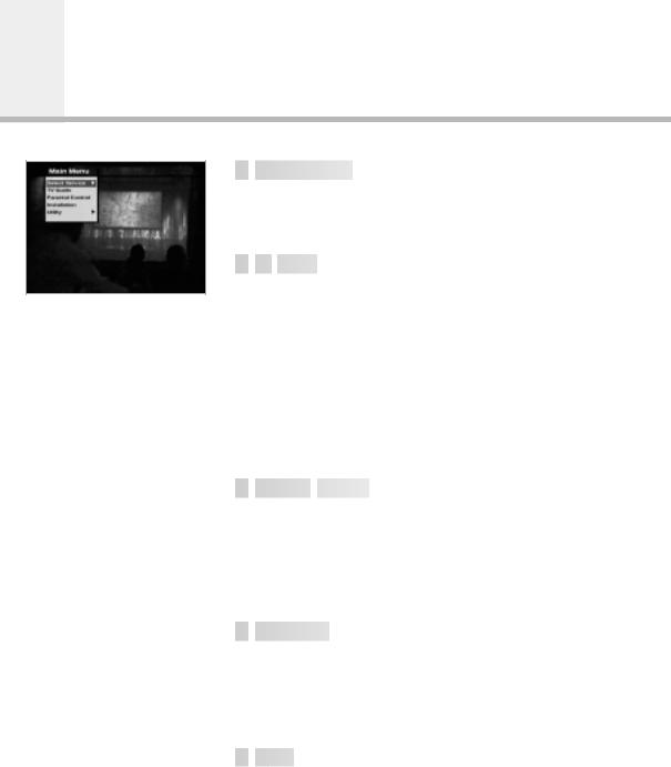
Guide of Main Menu

 1.
1. Select Service


The select service displays the required service list which can be viewed in Simple or Advanced mode.

 2.
2. TV
TV Guide
Guide


Your STB has an Electronic Programme Guide(EPG) to help you navigate through all the possible viewing options.
The TV Guide supplies information such as programme listings and start and end times for all available services.
In addition, detailed information about the programme listings and start and end times for all available services.
In addition, detailed information about the programme is often available in the EPG (the availability and amount of these programme details will vary, depending on the particular broadcaster).

 3.
3. Parental
 Control


Access to services and programmes is controlled by a PIN code (i.e., a 4-digit secret code that is defined by the user).
The very first time you attempt to lock all services(or lock programmes by ratings), the on-screen menu will instruct you to assign a PIN code(Later on, if necessary, you can change it).

 4.
4. Installation


The Installation mode allows you to have the information of setting services and newly set services(language, time, organise, search,..) Furthermore, you can recognize the states of hardware and software versions and signals from your STB.

 5.
5. Utility


This menu provides Calendar and Biorhythm.
E15
 Loading...