


HLMP-0300
HP HLMP-0300, HLMP-0301, HLMP-0504, HLMP-0400, HLMP-0401 Datasheet
...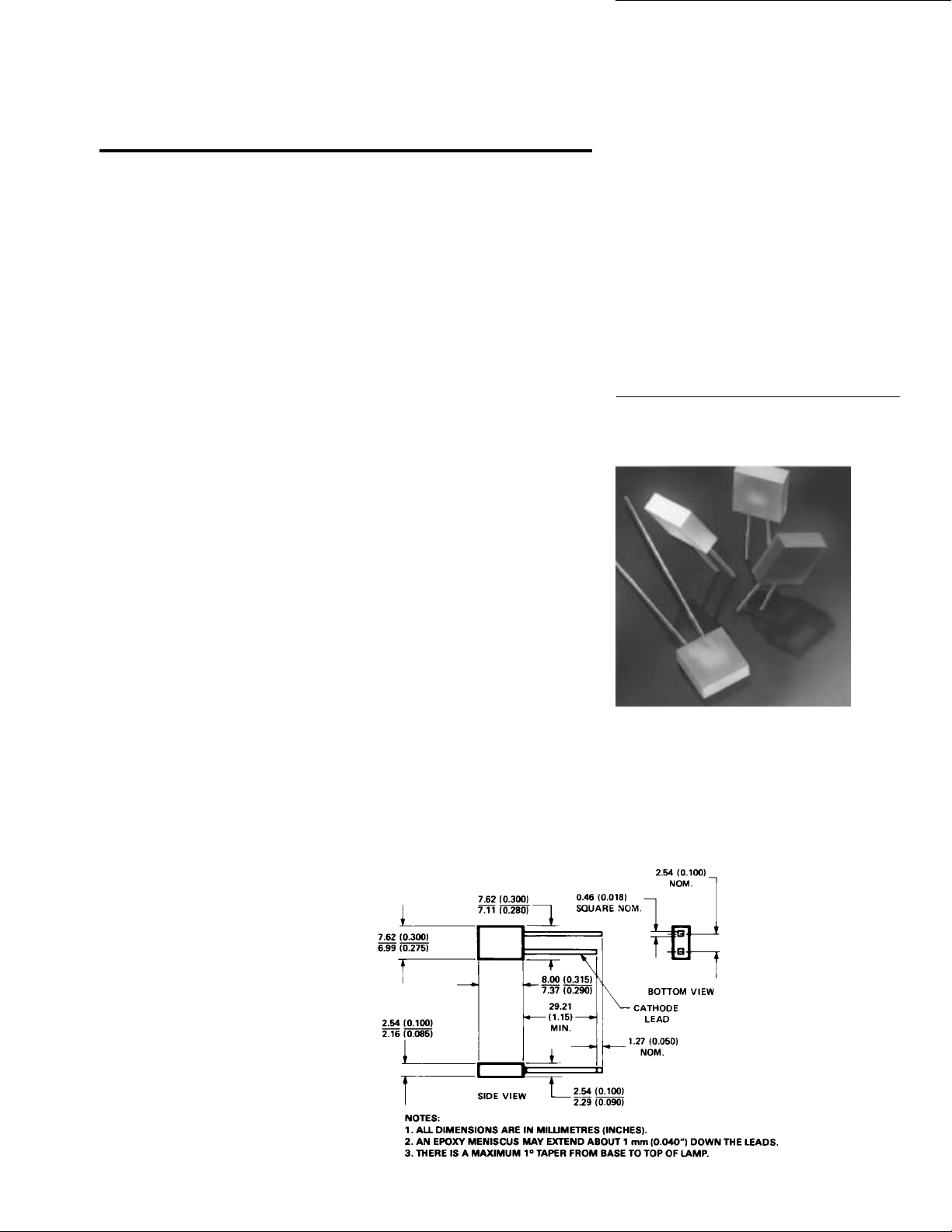
2.5 mm x 7.6 mm Rectangular
LED Lamps
Technical Data
H
HLMP-R100
HLMP-0300/0301
HLMP-0400/0401
HLMP-0503/0504
Features
• Rectangular Light Emitting
Surface
• Flat High Sterance Emitting
Surface
• Stackable on 2.54 mm (0.100
inch) Centers
• Ideal as Flush Mounted
Panel Indicators
• Ideal for Backlighting
Legends
• Long Life: Solid State
Reliability
• Choice of 4 Bright Colors
DH AS AlGaAs Red
High Efficiency Red
Yellow
High Performance Green
• IC Compatible/Low Current
Requirements
Description
The HLMP–R100, -030X, -040X,
-050X are solid state lamps
encapsulated in a radial lead
rectangular epoxy package. They
utilize a tinted, diffused epoxy to
provide high on-off contrast and a
flat high intensity emitting
surface. Borderless package
design allows creation of
uninterrupted light emitting areas.
The HLMP-R100 uses a double
heterojunction (DH) absorbing
substrate (AS) aluminum gallium
arsenide (AlGaAs) red LED chip
in a light red epoxy package. This
combination produces
outstanding light output over a
wide range of drive currents.
The HLMP-0300 and -0301 have a
high efficiency red GaAsP on GaP
LED chip in a light red epoxy
package.
The HLMP-0400 and -0401
provide a yellow GaAsP on GaP
LED chip in a yellow epoxy
package.
Package Dimensions
The HLMP-0503 and -0504
provide a green GaP LED chip in
a green epoxy package.
5964-9378E
1-149
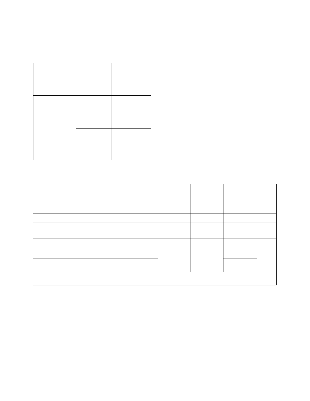
Axial Luminous Intensity
I (mcd) @
v
Color Number Min. Typ.
Part
DH AlGaAs Red HLMP-R100 3.4 11.0
High HLMP-0300 1.3 2.5
Efficiency
Red HLMP-0301 2.1 5.3
HLMP-0400 1.4 2.5
Yellow
HLMP-0401 3.6 5.0
High HLMP-0503 1.6 2.5
Performance
Green HLMP-0504 2.6 8.0
20 mA DC
Absolute Maximum Ratings at T
Parameter R100 0300/-0301 0400/0401 0503/-0504 Units
Peak Forward Current 300 90 60 90 mA
Average Forward Current
DC Current
Power Dissipation 87 135 85 135 mW
Reverse Voltage (IR = 100 µA) 5 5 5 5 V
Transient Forward Current
Operating Temperature Range -20 to -20 to
Storage Temperature Range -55 to -55 to
Lead Soldering Temperature 260°C for 5 seconds
(1.6 mm [0.063 in.] from body)
Notes:
1. See Figure 5 to establish pulsed operating conditions.
2. For AlGaAs Red, Red, and Green Series derate linearly from 50°C at 0.5 mA/°C. For Yellow Series derate linearly from 50°C at
0.2 mA/°C.
3. The transient peak current is the maximum non-recurring peak current that can be applied to the device without damaging the LED
die and wirebond. It is not recommended that the device be operated at peak current beyond the peak forward current listed in the
Absolute Maximum Ratings.
[2]
[1]
[3]
(10 µs Pulse) 500 500 500 500 mA
= 25°C
A
HLMP- HLMP- HLMP- HLMP-
20 25 20 25 mA
30 30 20 30 mA
+100 -55 to -55 to +100 °C
+100 +100
+100 +100
1-150
 Loading...