HP HLMP-1320, HLMP-1321, HLMP-1420, HLMP-1421, HLMP-1520 Datasheet
...
H
T-1 (3 mm) High Intensity
LED Lamps
Technical Data
Features
•High Intensity
•Choice of 3 Bright Colors
High Efficiency Red Yellow
High Performance Green
•Popular T-1 Diameter Package
•Selected Minimum Intensities
•Narrow Viewing Angle
HLMP-132X Series
HLMP-142X Series
HLMP-152X Series
•General Purpose Leads
•Reliable and Rugged
•Available on Tape and Reel
Description
This family of T-1 lamps is specially designed for applications requiring higher on-axis intensity than is achievable with a standard lamp. The light generated is focused to a narrow beam to achieve this effect.
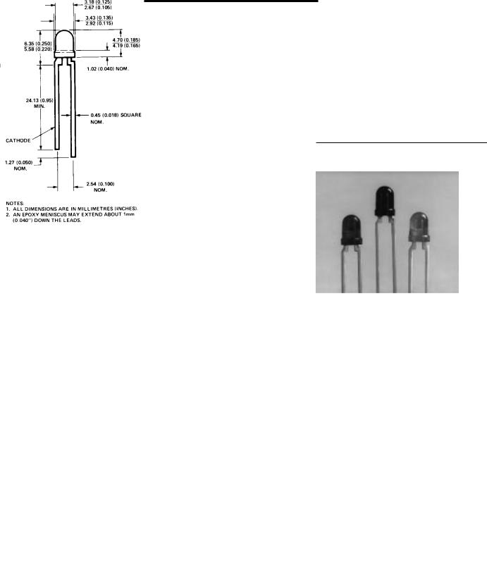
Package Dimensions |
Selection Guide |
|
|
|
|
||
|
|
|
|
|
|
|
|
|
|
|
|
Minimum |
|
|
|
|
|
Part |
|
Intensity |
|
|
|
|
|
Number |
|
(mcd) at |
Color |
|
|
|
|
HLMP- |
Description |
10 mA |
(Material) |
|
|
|
|
|
|
|
|
|
|
|
|
1320 |
Untinted |
8.6 |
High Efficiency Red |
|
|
|
|
|
|
||||
|
|
|
Nondiffused |
|
(GaAsP on GaP) |
|
|
|
|
|
|
|
|
|
|
|
|
1321 |
Tinted |
8.6 |
|
|
|
|
|
|
|
|
|||
|
|
|
Nondiffused |
|
|
|
|
|
|
|
|
|
|
|
|
|
|
1420 |
Untinted |
9.2 |
Yellow |
|
|
|
|
|
Nondiffused |
|
(GaAsP on GaP) |
|
|
|
|
|
|
|
|
|
|
|
|
|
|
|
|
|
|
|
|
1421 |
Tinted |
9.2 |
|
|
|
|
|
|
|
|
|||
|
|
|
Nondiffused |
|
|
|
|
|
|
|
|
|
|
|
|
|
|
1520 |
Untinted |
6.7 |
Green (GaP) |
|
|
|
|
|
Nondiffused |
|
|
|
|
|
|
|
|
|
|
|
|
|
|
|
|
|
|
|
|
|
|
1521 |
Tinted |
6.7 |
|
|
|
|
|
|
|
|
|||
|
|
|
Nondiffused |
|
|
|
|
1-128 |
5964-9373E |
Absolute Maximum Ratings at TA = 25°C
Parameter |
Red |
Yellow |
Green |
Units |
|
|
|
|
|
Peak Forward Current |
90 |
60 |
90 |
mA |
|
|
|
|
|
Average Forward Current[1] |
25 |
20 |
25 |
mA |
DC Current[2] |
30 |
20 |
30 |
mA |
Power Dissipation[3] |
135 |
85 |
135 |
mW |
Reverse Voltage (IR = 100 μA) |
5 |
5 |
5 |
V |
Transient Forward Current[4] |
500 |
500 |
500 |
mA |
(10 μsec Pulse) |
|
|
|
|
LED Junction Temperature |
110 |
110 |
110 |
°C |
Operating Temperature Range |
-55 to +100 |
-55 to +100 |
-20 to +100 |
°C |
|
|
|
|
|
|
|
|
|
|
Storage Temperature Range |
|
|
-55 to +100 |
|
|
|
|
|
|
Lead Soldering Temperature |
|
260°C for 5 seconds |
|
|
[1.6 mm (0.063 in.) from body] |
|
|
|
|
|
|
|
|
|
Notes:
1.See Figure 5 (Red), 10 (Yellow), or 15 (Green) to establish pulsed operating conditions.
2.For Red and Green series derate linearly from 50°C at 0.5 mA/°C. For Yellow series derate linearly from 50°C at 0.2 mA/°C.
3.For Red and Green series derate power linearly from 25°C at 1.8 mW/°C. For Yellow series derate power linearly from 50°C at 1.6 mW/°C.
4.The transient peak current is the maximum non-recurring peak current that can be applied to the device without damaging the LED die and wirebond. It is not recommended that the device be operated at peak currents beyond the peak forward current listed in the Absolute Maximum Ratings.
1-129
 Loading...