


 Loading...
HP EliteBook 755 G4 Notebook PC HP EliteBook 745 G4 Notebook PC
Maintenance and Service Guide
© Copyright 2016 HP Development Company,
L.P.
AMD and AMD Radeon are trademarks of Advanced Micro Devices, Inc. Bluetooth is a trademark owned by its proprietor and used by HP Inc. under license. Microsoft and Windows are either registered trademarks or trademarks of Microsoft Corporation in the United States and/or other countries.
Product notice
This guide describes features that are common to most models. Some features may not be available on your computer.
Not all features are available in all editions of Windows 10 or Windows 8. This computer may require upgraded and/or separately purchased hardware, drivers and/or software to take full advantage of Windows 10 or Windows 8 functionality. See http://www.microsoft.com for details.
The information contained herein is subject to change without notice. The only warranties for HP products and services are set forth in the express warranty statements accompanying such products and services. Nothing herein should be construed as constituting an additional warranty. HP shall not be liable for technical or editorial errors or omissions contained herein.
First Edition: December 2016
Document Part Number: 902206-001

Important Notice about Customer Self-Repair Parts
 CAUTION: Your computer includes Customer Self-Repair parts and parts that should only be accessed by an authorized service provider. See Chapter 5, "Removal and replacement procedures for Customer Self-Repair parts," for details. Accessing parts described in Chapter 6, "Removal and replacement procedures for Authorized Service Provider only parts," can damage the computer or void your warranty.
iii
iv Important Notice about Customer Self-Repair Parts

Safety warning notice
 WARNING! To reduce the possibility of heat-related injuries or of overheating the device, do not place the device directly on your lap or obstruct the device air vents. Use the device only on a hard, at surface. Do not allow another hard surface, such as an adjoining optional printer, or a soft surface, such as pillows or rugs or clothing, to block air ow. Also, do not allow the AC adapter to contact the skin or a soft surface, such as pillows or rugs or clothing, during operation. The device and the AC adapter comply with the user-accessible surface temperature limits de ned by the International Standard for Safety of Information Technology Equipment (IEC 60950-1).
v
vi Safety warning notice

Table of contents
1 Product description ....................................................................................................................................... |
1 |
2 External component dent c t on .................................................................................................................. |
6 |
Right ....................................................................................................................................................................... |
6 |
Left ......................................................................................................................................................................... |
8 |
Display .................................................................................................................................................................... |
9 |
Top ........................................................................................................................................................................ |
10 |
TouchPad ........................................................................................................................................... |
10 |
Lights ................................................................................................................................................. |
11 |
Buttons, speakers, and ngerprint reader ........................................................................................ |
14 |
Special function keys ........................................................................................................................ |
16 |
Using the hot keys ............................................................................................................................. |
17 |
Bottom ................................................................................................................................................................. |
19 |
Front ..................................................................................................................................................................... |
20 |
Locating system information .............................................................................................................................. |
20 |
3 Illustrated parts catalog .............................................................................................................................. |
22 |
Computer major components .............................................................................................................................. |
22 |
Display assembly subcomponents ...................................................................................................................... |
25 |
Plastics kit ............................................................................................................................................................ |
26 |
Mass storage devices ........................................................................................................................................... |
27 |
Miscellaneous parts ............................................................................................................................................. |
28 |
4 Removal and replacement procedures preliminary requirements .................................................................... |
30 |
Tools required ...................................................................................................................................................... |
30 |
Service considerations ......................................................................................................................................... |
30 |
Plastic parts ....................................................................................................................................... |
30 |
Cables and connectors ...................................................................................................................... |
31 |
Drive handling ................................................................................................................................... |
31 |
Grounding guidelines ........................................................................................................................................... |
32 |
Electrostatic discharge damage ........................................................................................................ |
32 |
Packaging and transporting guidelines .......................................................................... |
33 |
Workstation guidelines ................................................................................................... |
33 |
Equipment guidelines ..................................................................................................... |
34 |
vii
5 Removal and replacement procedures for Customer Self-Repair parts ............................................................. |
35 |
Component replacement procedures .................................................................................................................. |
35 |
Bottom cover ..................................................................................................................................... |
35 |
Battery ............................................................................................................................................... |
40 |
Hard drive .......................................................................................................................................... |
41 |
SSD ..................................................................................................................................................... |
43 |
Memory modules ............................................................................................................................... |
44 |
WLAN/Bluetooth combo card ............................................................................................................ |
46 |
WWAN module ................................................................................................................................... |
48 |
Keyboard ........................................................................................................................................... |
50 |
6 Removal and replacement procedures for Authorized Service Provider parts ................................................... |
53 |
Component replacement procedures .................................................................................................................. |
53 |
RTC battery ........................................................................................................................................ |
54 |
Internal base plate ............................................................................................................................ |
55 |
Heat sink/fan assembly .................................................................................................................... |
58 |
Fingerprint reader assembly ............................................................................................................. |
61 |
Power button board .......................................................................................................................... |
62 |
Touchpad button board ..................................................................................................................... |
65 |
NFC module ....................................................................................................................................... |
67 |
Smart card reader board ................................................................................................................... |
68 |
USB/VGA board .................................................................................................................................. |
70 |
System board .................................................................................................................................... |
71 |
Speaker assembly ............................................................................................................................. |
74 |
Display assembly ............................................................................................................................... |
76 |
Top cover ........................................................................................................................................... |
81 |
7 Computer Setup (BIOS), TPM, and HP Sure Start in Windows 10 ........................................................................ |
82 |
Using Computer Setup ......................................................................................................................................... |
82 |
Starting Computer Setup .................................................................................................................. |
82 |
Navigating and selecting in Computer Setup ................................................................................... |
82 |
Restoring factory settings in Computer Setup ................................................................................. |
82 |
Updating the BIOS ............................................................................................................................. |
83 |
Determining the BIOS version ......................................................................................... |
83 |
Downloading a BIOS update ........................................................................................... |
84 |
Changing the boot order using the f9 prompt .................................................................................. |
84 |
TPM BIOS settings (select products only) ........................................................................................................... |
85 |
Using HP Sure Start (select products only) ......................................................................................................... |
85 |
viii
8 Computer Setup (BIOS), TPM, and HP Sure Start in Windows 7 ......................................................................... |
86 |
Using Computer Setup ......................................................................................................................................... |
86 |
Starting Computer Setup .................................................................................................................. |
86 |
Navigating and selecting in Computer Setup ................................................................................... |
86 |
Restoring factory settings in Computer Setup ................................................................................. |
87 |
Updating the BIOS ............................................................................................................................. |
88 |
Determining the BIOS version ......................................................................................... |
88 |
Downloading a BIOS update ........................................................................................... |
88 |
Changing the boot order using the f9 prompt .................................................................................. |
89 |
TPM BIOS settings (select products only) ........................................................................................................... |
89 |
Using HP Sure Start (select products only) ......................................................................................................... |
90 |
9 Using HP PC Hardware Diagnostics (UEFI) ....................................................................................................... |
91 |
Downloading HP PC Hardware Diagnostics (UEFI) to a USB device .................................................................... |
91 |
10 Backing up and recovering Windows 10 ....................................................................................................... |
93 |
Creating recovery media and backups ................................................................................................................ |
93 |
Creating HP Recovery media (select products only) ......................................................................... |
93 |
Using Windows tools ........................................................................................................................................... |
94 |
Restore and recovery ........................................................................................................................................... |
95 |
Recovering using HP Recovery Manager ........................................................................................... |
95 |
What you need to know before you get started ............................................................. |
95 |
Using the HP Recovery partition (select products only) ................................................. |
96 |
Using HP Recovery media to recover .............................................................................. |
96 |
Changing the computer boot order ................................................................................ |
97 |
Removing the HP Recovery partition (select products only) ......................................... |
98 |
11 Backing up and recovering Windows 7 ......................................................................................................... |
99 |
Creating recovery media and backups ................................................................................................................ |
99 |
Guidelines .......................................................................................................................................... |
99 |
Creating recovery media with HP Recovery Disc Creator ................................................................. |
99 |
Creating recovery media ............................................................................................... |
100 |
Backing up your information .......................................................................................................... |
100 |
Performing a system recovery .......................................................................................................................... |
101 |
Using the Windows recovery tools .................................................................................................. |
101 |
Using f11 recovery tools (select models only) ............................................................................... |
102 |
Using Windows 7 operating system media ..................................................................................... |
102 |
12 pec c t ons .......................................................................................................................................... |
104 |
Input power ........................................................................................................................................................ |
104 |
ix
|
Operating environment ..................................................................................................................................... |
104 |
13 |
Power cord set requirements .................................................................................................................... |
105 |
|
Requirements for all countries .......................................................................................................................... |
105 |
|
Requirements for speci c countries and regions ............................................................................................. |
105 |
14 |
Statement of memory volatility ................................................................................................................ |
107 |
|
Nonvolatile memory usage ............................................................................................................................... |
109 |
|
Questions and answers ..................................................................................................................................... |
111 |
|
Using HP Sure Start (select models only) .......................................................................................................... |
112 |
15 |
Recycling ................................................................................................................................................ |
113 |
Index ........................................................................................................................................................... |
114 |
|
x
1Product description
Category |
Description |
|
|
|
|
Product Name |
HP 755 G4 Notebook PC |
|
|
HP 745 G4 Notebook PC |
|
|
|
|
Processors |
AMD® processors: |
|
|
● A12 Pro-9800B 2.7 GHz (max turbo frequency 3.6 GHz), DDR4-1866, 2 MB L2 Cache, 15 W |
|
|
● A12 Pro-8830B 2.1 GHz (max turbo frequency 3.4 GHz), DDR4-1866, 2 MB L2 Cache, 15 W |
|
|
● A10 Pro-8730B 1.8 GHz (max turbo frequency 3.2 GHz), DDR4-1866, 2 MB L2 Cache, 15 W |
|
|
● A8 Pro-9600B 2.4 GHz (max turbo frequency 3.3 GHz), DDR4-1866, 2 MB L2 Cache, 15 W |
|
|
|
|
Chipset |
Integrated with processor |
|
|
|
|
Graphics |
Internal graphics: |
|
|
AMD UMA graphics (with shared video memory) |
|
|
AMD Vivid Color Support |
|
|
Dual-display ports supported through docking solution |
|
|
Up to three independent displays supported with docking solution |
|
|
AMD Radeon R7 (A12 Pro-9800B, A12 Pro-8830B) |
|
|
AMD Radeon R5 (A10 Pro-8730B, A8 Pro-9600B) |
|
|
|
|
Panel |
39.6-cm (15.6-in), eDP 1.2 slim, high-de nition (HD), AntiGlare (AG), SVA (1366 x 768) display with and |
|
|
without webcam |
|
|
39.6-cm (15.6-in), eDP 1.2 slim, full high-de |
nition (FHD), AntiGlare (AG), SVA (1920 x 1080) display with and |
|
without webcam |
|
|
39.6-cm (15.6-in), eDP 1.2 slim, full high-de |
nition (FHD), SVA (1920 x 1080) display with touch and webcam |
|
35.6-cm (14-in), eDP 1.2 slim, high-de nition (HD), AntiGlare (AG), SVA (1366 x 768) display with and without |
|
|
webcam |
|
|
35.6-cm (14-in), eDP 1.2 slim, full high-de nition (FHD), AntiGlare (AG), SVA (1920 x 1080) display with and |
|
|
without webcam |
|
|
35.6-cm (14-in), eDP + PSR ultraslim, quarter high-de nition (QHD), AntiGlare (AG), UWVA (2560 x 1440) |
|
|
display with and without webcam |
|
|
35.6-cm (14-in), eDP 1.2 slim, full high-de nition (FHD), SVA (1920 x 1080) display with touch and webcam |
|
|
All display assemblies include two wireless local area network (WLAN) antenna cables and NFC antenna |
|
|
WWAN models include two wireless wide area network (WWAN) antenna cables |
|
|
|
|
Memory |
Two memory module slots |
|
|
Memory is customer accessible. |
|
|
DDR3L -12800 (1600 MHz) dual channel support |
|
|
DDR4 PC4 (1866 MHz) support |
|
|
Supports up to 16 GB of system RAM |
|
1

Category |
Description |
|
||
|
|
|
||
|
● |
16384 MB (8192 MB×2) |
||
|
● |
12288 MB (8192 MB + 4096 MB) (not available in Brazil on the 35.6-cm) |
||
|
● |
8192 MB (8192 MB×1 or 4096 MB×2) |
||
|
● |
4096 MB (4096 MB×1) |
||
|
|
|
|
|
Hard drive |
HDDs: |
|
|
|
|
Supports 6.35 cm (2.5 in) hard drives in 7.0 mm (.28 in) thicknesses (all hard drives use the same bracket) |
|||
|
Serial ATA |
|
||
|
● |
1 TB, 5400 rpm, 6.35 mm |
||
|
● |
500 GB, 7200 rpm, 6.35 mm, self-encrypting (FIPS-140-2) |
||
|
● |
500 GB, 7200 rpm, 6.35 mm, self-encrypting (Opal 2) |
||
|
● |
500 GB, 7200 rpm, 6.35 mm |
||
|
|
|
|
|
|
SSDs: |
|
|
|
|
● |
M.2 |
(2280) |
512 GB SATA-3 SS TLC (FIPS-140-2) (not available in Brazil on the 35.6-cm) |
|
● |
M.2 |
(2280) |
512 GB PCIe NVMe TLC (not available in Brazil on the 35.6-cm) |
|
● |
M.2 |
(2280) |
360 GB PCIe-3×4 SS TLC (not available in Brazil on the 35.6-cm) |
|
● |
M.2 |
(2280) |
256 GB SATA-3 SS TLC (Opal 2) (not available in Brazil on the 35.6-cm) |
|
● |
M.2 |
(2280) |
256 GB NVMe TLC (not available in Brazil on the 35.6-cm) |
|
● |
M.2 |
(2280) |
128 GB SATA-3 SS |
|
|
|
||
Audio and video |
Supports: |
|
||
|
HP Bang & Olufsen Audio |
|||
|
Dual-array microphone |
|||
|
Dual speakers |
|
||
|
Webcam (720p) |
|
||
|
|
|
||
Ethernet |
● |
Broadcom 5762 10/100/1000 Ethernet NIC with DASH Support |
||
|
S3/S4/S5 Wake-on-LAN |
|||
|
|
|
|
|
Wireless |
WLAN |
|
|
|
Integrated wireless local area network (WLAN) options by way of wireless module
Two WLAN antennas built into display assembly
Integrated wireless personal area network (PAN) supported by Bluetooth® 4.0 or Bluetooth 4.2 combo card Supports the following WLAN formats:
●Realtek RTL8723BE-VB 802.11bgn solo-band 1x1 Wi-Fi Adapter + BT 4.0 combo adapter
●Intel Dual Band Wireless-AC 7265 802.11ac non-vPro 2x2 Wi-Fi Adapter + BT 4.2 combo adapter
●Intel Dual Band Wireless-AC 3168 802.11ac non-vPro 1x1 Wi-Fi Adapter + BT 4.2 combo adapter Supports no WLAN option
Compatible with iracast-certi ed devices
Compatible with HP Sure Connect
NFC
2Chapter 1 Product description

Category |
Description |
|
|
|
|
|
|
|
Supports the following NFC formats: |
|
|
|
Integrated NFC Galapagos NXP NPC100 12C NCI 10 mm x 25 mm module (not available in Brazil) |
||
|
NFC antenna |
|
|
|
Supports no NFC option |
|
|
|
|
|
|
|
WWAN |
|
|
|
Integrated wireless wide area network (WWAN) options by way of wireless module |
||
|
Two WWAN antennas built into display assembly |
|
|
|
Supports the following WWAN formats: |
|
|
|
● |
HP lt4120 LTE/EVDO/HSPA+ with GPS M.2 Mobile Broadband Module |
|
|
● |
HP lt4132 LTE/HSPA + with GPS M.2 Mobile Broadband Module |
|
|
● |
HP hs3210 WW HSPA+ Mobile Broadband Module (available in China, Japan, Taiwan, Indonesia, Russia, |
|
|
|
and Ukraine with non-vPro WLAN only) |
|
|
Supports no WWAN option |
|
|
|
|
|
|
External media cards |
Memory card reader (SD, SDHC, SDXC) |
|
|
|
|
|
|
Ports |
VGA |
|
|
|
USB 3.x charging |
|
|
|
USB 3.x |
|
|
|
USB Type-C |
|
|
|
DisplayPort |
|
|
|
RJ-45 |
|
|
|
Docking connector |
|
|
|
Audio-out (headphone)/audio-in (microphone) combo jack |
||
|
AC port |
|
|
|
|
|
|
Keyboard/pointing |
Keyboard: |
|
|
devices |
Dura keys, backlit, spill resistant with drain |
|
|
|
|
||
|
Spill resistant with drain |
|
|
|
|
|
|
|
TouchPad: |
|
|
|
Gestures enabled by default: twonger scrolling, two- |
nger pinch-zoom |
|
|
Taps enabled by default |
|
|
|
n/o |
button |
|
|
|
|
|
|
Glass |
|
|
|
|
|
|
Power requirements |
65 W HP Smart AC adapter |
|
|
|
45 W HP Smart AC adapter |
|
|
|
45 W, 2-prong AC adapter |
|
|
|
|
|
|
Security |
Security lock |
|
|
|
Fingerprint reader |
|
|
|
Supports Trusted Platform Module (TPM) 1.2 or 2.0 n |
neon, soldered down) |
|
3

Category |
Description |
|
|
|
|
||
|
Integrated Smart Card reader (active) |
||
|
Preboot authentication (password, smart card) |
||
|
|
|
|
Operating system |
Preinstalled: |
|
|
|
● |
Windows® 7 Professional 64-bit |
|
|
● |
Windows 7 Home Basic 64-bit Chinese Market (CPPP) |
|
|
● |
Windows 10 Home |
64-bit Chinese Market (CPPP) |
|
● |
Windows 10 Home |
64-bit High-end |
|
● |
Windows 10 Home |
64 High-end Single Language |
|
● |
Windows 10 Home |
64-bit High-end Chinese Market |
|
● |
Windows 10 Professional 64-bit |
|
|
● |
Windows 10 Professional 64-bit StF MSNA Standard |
|
|
● |
Windows 10 Professional 64-bit StF MSNA High-end |
|
|
● |
Windows 10 Professional 64-bit with downgrade to Windows 7 64-bit |
|
|
● |
Windows 10 Professional 64-bit with downgrade to Windows 7 64-bit Volume License |
|
|
● |
Windows 10 Professional 64-bit with downgrade to Windows 7 64-bit StF MSNA Standard |
|
|
● |
Windows 10 Professional 64-bit with downgrade to Windows 7 64-bit StF MSNA High-End |
|
|
● |
Windows 10 Home |
64-bit |
|
● |
Windows 10 Home |
64-bit Single Language |
|
● |
FreeDOS 2.0 |
|
|
|
||
|
Restore Media–DR/SR-DVD |
||
|
● |
Windows 7 |
|
|
● |
Windows 10 |
|
|
Restore Media–DR-USB |
|
|
|
● |
Windows 10 |
|
|
Restore Media–OS-DVD |
|
|
|
● |
Windows 7 Professional 64-bit |
|
|
● |
Windows 10 Home |
64-bit |
|
● |
Windows 10 Pro 64-bit |
|
Restore Media–OS-USB
●Windows 10 Pro 64-bit
ert ed
|
● |
Microsoft WHQL |
|
|
|
|
Web-only support |
|
|
● |
Windows 10 Enterprise |
|
● Windows 7 Pro 64-bit (DDR4 memory only) |
|
|
● Windows 7 Enterprise 64-bit (DDR4 memory only) |
|
|
|
|
Serviceability |
End user replaceable parts: |
|
4Chapter 1 Product description

Category |
Description |
|
|
|
AC adapter |
|
Battery |
|
Hard drive |
|
SSD |
|
Memory module |
|
WLAN |
|
WWAN |
|
Keyboard |
|
|
5

2 External component dent c t on
Right
Component |
|
Description |
|
|
|
|
|
(1) |
USB Type-C charging port |
Connects a USB device with a Type-C connector and can charge |
|
|
|
products such as cell phones, laptops, tablets, and MP3 players, |
|
|
|
even when the computer is o . |
|
|
|
NOTE: Adapters (purchased separately) may be required. |
|
|
|
|
|
(2) |
Dual-Mode DisplayPort |
Connects an optional digital display device, such as a high- |
|
|
|
performance monitor or projector. |
|
|
|
|
|
(3) |
Memory card reader |
Reads optional memory cards that store, manage, share, or |
|
|
|
access information. |
|
|
|
|
|
(4) |
Audio-out (headphone)/Audio-in (microphone) |
Connects optional powered stereo speakers, headphones, |
|
|
combo jack |
earbuds, a headset, or a television audio cable. Also connects an |
|
|
|
optional headset microphone. This jack does not support |
|
|
|
optional standalone microphones. |
|
|
|
WARNING! To reduce the risk of personal injury, adjust the |
|
|
|
volume before putting on headphones, earbuds, or a headset. |
|
|
|
For additional safety information, refer to the Regulatory, |
|
|
|
Safety, and Environmental Notices. |
|
|
|
To access this guide: |
|
|
|
1. |
Type support in the taskbar search box, and then select |
|
|
|
the HP Support Assistant app. |
|
|
|
‒ or – |
|
|
|
Click the question mark icon in the taskbar. |
|
|
2. |
Select My PC, select the pec c t ons tab, and then |
|
|
|
select User Guides. |
|
|
NOTE: When a device is connected to the jack, the computer |
|
|
|
speakers are disabled. |
|
|
|
|
|
(5) |
USB 3.0 port |
Connects an optional USB device, such as a keyboard, mouse, |
|
|
|
external drive, printer, scanner or USB hub. |
|
|
|
|
|
6 Chapter 2 External component identi cation

Component |
|
Description |
|
|
|
|
|
(6) |
RJ-45 (network) jack/status lights |
Connects a network cable. |
|
|
|
● |
Green (left): The network is connected. |
|
|
● |
Amber (right): Activity is occurring on the network. |
|
|
|
|
(7) |
Docking connector |
Connects an optional docking device. |
|
|
|
|
|
(8) |
SIM card slot |
Supports a wireless subscriber identity module (SIM) card. The |
|
|
|
SIM card slot is located inside the battery bay. |
|
|
|
|
|
(9) |
Power connector |
Connects an AC adapter. |
|
|
|
|
|
Right 7

Left
Component |
|
Description |
|
|
|
(1) |
Security cable slot |
Attaches an optional security cable to the computer. |
|
|
NOTE: The security cable is designed to act as a deterrent, but |
|
|
it may not prevent the computer from being mishandled or |
|
|
stolen. |
|
|
|
(2) |
Vents |
Enable air ow to cool internal components. |
|
|
NOTE: The computer fan starts up automatically to cool |
|
|
internal components and prevent overheating. It is normal for |
|
|
the internal fan to cycle on and o during routine operation. |
|
|
|
(3) |
External monitor port |
Connects an external VGA monitor or projector. |
|
|
|
(4) |
USB 3.0 charging (powered) port |
Connects an optional USB device, such as a keyboard, mouse, |
|
|
external drive, printer, scanner or USB hub. Standard USB ports |
|
|
will not charge all USB devices or will charge using a low current. |
|
|
Some USB devices require power and require you to use a |
|
|
powered port. |
|
|
NOTE: USB charging ports can also charge select models of |
|
|
cell phones and MP3 players, even when the computer is o . |
|
|
|
(5) |
Smart card reader |
Supports optional smart cards. |
|
|
|
8 Chapter 2 External component identi cation

Display
Component |
Description |
|
|
|
|
(1) |
WLAN antennas* |
Send and receive wireless signals to communicate with wireless local |
|
|
area networks (WLANs). |
|
|
|
(2) |
WWAN antennas* |
Send and receive wireless signals to communicate with wireless wide |
|
|
area networks (WWANs). |
|
|
|
(3) |
Internal microphones |
Record sound. |
|
|
|
(4) |
Webcam light |
On: The webcam is in use. |
|
|
|
(5) |
Webcam |
Records video and captures photographs. Some models allow you to |
video conference and chat online using streaming video. To use the webcam:
▲ Type camera in the taskbar search box, and then select
Camera.
*The antennas are not visible from the outside of the computer. For optimal transmission, keep the areas immediately around the antennas free from obstructions.
For wireless regulatory notices, see the section of the Regulatory, Safety, and Environmental Notices that applies to your country or region.
To access this guide:
1.Type support in the taskbar search box, and then select the HP Support Assistant app.
‒ or –
Click the question mark icon in the taskbar.
2. Select My PC, select the pec c t ons tab, and then select User Guides.
Display 9
Top
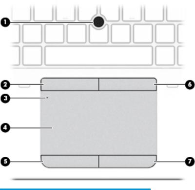
TouchPad
Component |
|
Description |
|
|
|
|
|
(1) |
Pointing stick (select products only) |
Moves the pointer and selects or activates items on the screen. |
|
|
|
|
|
(2) |
Left pointing stick button (select products only) |
Functions like the left button on an external mouse. |
|
|
|
|
|
(3) |
TouchPad on/o button/TouchPad light |
Turns the TouchPad on and o . |
|
|
|
● |
On: The TouchPad is o . |
|
|
● |
The TouchPad is on. |
|
|
|
|
(4) |
TouchPad zone |
Reads your nger gestures to move the pointer or activate |
|
|
|
items on the screen. |
|
|
|
|
|
(5) |
Left TouchPad button |
Functions like the left button on an external mouse. |
|
|
|
|
|
(6) |
Right pointing stick button (select products |
Functions like the right button on an external mouse. |
|
|
only) |
|
|
|
|
|
|
(7) |
Right TouchPad button |
Functions like the right button on an external mouse. |
|
|
|
|
|
10 Chapter 2 External component identi cation

Lights
 NOTE: Refer to the illustration that most closely matches your computer.
Component |
|
Description |
|
|
|
|
|
(1) |
Power light |
● |
On: The computer is on. |
|
|
● |
Blinking: The computer is in the Sleep state, a power-saving |
|
|
|
state. The computer shuts o power to the display and |
|
|
|
other unneeded components. |
|
|
● |
The computer is o or in Hibernation. Hibernation is a |
|
|
|
power-saving state that uses the least amount of power. |
|
|
|
|
(2) |
Microphone mute light |
● |
Amber: microphone sound is o . |
|
|
● |
microphone sound is on. |
|
|
|
|
(3) |
Num lock light |
On: Num lock is on. |
|
|
|
|
|
(4) |
Wireless light |
On: An integrated wireless device, such as a wireless local area |
|
|
|
network (WLAN) device and/or a Bluetooth® device, is on. |
|
|
|
NOTE: On some models, the wireless light is amber when all |
|
|
|
wireless devices are o . |
|
|
|
|
|
(5) |
Mute light |
● |
Amber: Computer sound is o . |
|
|
● |
Computer sound is on. |
|
|
|
|
(6) |
Caps lock light |
On: Caps lock is on, which switches the key input to all capital |
|
|
|
letters. |
|
|
|
|
|
(7) |
TouchPad light |
● |
On: The TouchPad is o . |
Top 11

Component |
Description |
|
|
|
|
|
● |
The TouchPad is on. |
|
|
|
Component |
|
Description |
|
|
|
|
|
(1) |
Power light |
● |
On: The computer is on. |
|
|
● |
Blinking: The computer is in the Sleep state, a power-saving |
|
|
|
state. The computer shuts o power to the display and |
|
|
|
other unneeded components. |
|
|
● |
The computer is o or in Hibernation. Hibernation is a |
|
|
|
power-saving state that uses the least amount of power. |
|
|
|
|
(2) |
Microphone mute light |
● |
Amber: microphone sound is o . |
|
|
● |
microphone sound is on. |
|
|
|
|
(3) |
Num lock light |
On: Num lock is on. |
|
|
|
|
|
(4) |
Wireless light |
On: An integrated wireless device, such as a wireless local area |
|
|
|
network (WLAN) device and/or a Bluetooth® device, is on. |
|
|
|
NOTE: On some models, the wireless light is amber when all |
|
|
|
wireless devices are o . |
|
|
|
|
|
(5) |
Mute light |
● |
Amber: Computer sound is o . |
|
|
● |
Computer sound is on. |
|
|
|
|
12 Chapter 2 External component identi cation

Component |
|
Description |
|
|
|
|
|
(6) |
Caps lock light |
On: Caps lock is on, which switches the key input to all capital |
|
|
|
letters. |
|
|
|
|
|
(7) |
TouchPad light |
● |
On: The TouchPad is o . |
|
|
● |
The TouchPad is on. |
|
|
|
|
Top 13

Buttons, speakers, and n erpr nt reader
Component |
|
Description |
|
|
|
|
|
(1) |
Power button |
● |
When the computer is o , press the button to turn on the |
|
|
|
computer. |
|
|
● |
When the computer is on, press the button brie y to initiate |
|
|
|
Sleep. |
|
|
● |
When the computer is in the Sleep state, press the button |
|
|
|
brie y to exit Sleep. |
|
|
● |
When the computer is in Hibernation, press the button |
|
|
|
brie y to exit Hibernation. |
|
|
CAUTION: Pressing and holding down the power button results |
|
|
|
in the loss of unsaved information. |
|
|
|
If the computer has stopped responding and shutdown |
|
|
|
procedures are ine ective, press and hold the power button for at |
|
|
|
least 5 seconds to turn o the computer. |
|
|
|
To learn more about your power settings, see your power |
|
|
|
options. |
|
|
|
▲ |
Type power in the taskbar search box, and then select |
|
|
|
Power and sleep settings. |
|
|
|
‒ or – |
|
|
|
Right-click the Start button, and then select Power |
|
|
|
Options. |
|
|
|
|
(2) |
Premium speakers (select products only) |
Produce sound. |
|
|
|
|
|
(3) |
Wireless button |
Turns the wireless feature on or o but does not establish a |
|
|
|
wireless connection. |
|
14 Chapter 2 External component identi cation

Component |
|
Description |
|
|
|
|
|
A wireless network must be set up before a wireless connection is |
|
|
possible. |
|
|
|
(4) |
Volume mute button |
Mutes and restores speaker sound. |
|
|
|
(5) |
Fingerprint reader (select products only) |
Allows a ngerprint logon to Windows, instead of a password |
|
|
logon. |
|
|
|
Top 15

Special function keys
 NOTE: Refer to the illustration that most closely matches your computer.
Component |
|
Description |
|
|
|
(1) |
esc key |
Displays system information when pressed in combination with |
|
|
the fn key. |
|
|
|
(2) |
fn key |
Executes frequently used system functions when pressed in |
|
|
combination with a function key, the num lock key, or the esc |
|
|
key. |
|
|
See Using the hot keys on page 17. |
|
|
|
(3) |
Windows key |
Opens the Start menu. |
|
|
NOTE: Pressing the Windows key again will close the Start |
|
|
menu. |
|
|
|
(4) |
Embedded numeric keypad |
A numeric keypad superimposed over the keyboard alphabet |
|
|
keys that enables you to add, subtract, and perform other |
|
|
numeric tasks. When num lock is on, the keypad can be used like |
|
|
an external numeric keypad. |
|
|
|
(5) |
Windows application key |
Displays options for a selected object. |
|
|
|
(6) |
num lock key |
Turns the embedded numeric keypad on and o . |
|
|
|
16 Chapter 2 External component identi cation
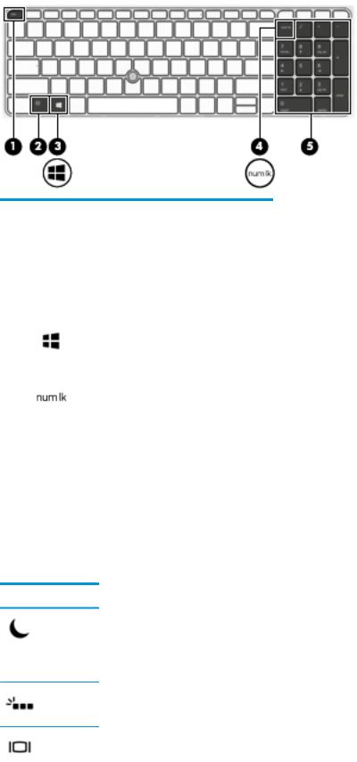
Component |
|
Description |
|
|
|
(1) |
esc key |
Displays system information when pressed in combination with |
|
|
the fn key. |
|
|
|
(2) |
fn key |
Executes frequently used system functions when pressed in |
|
|
combination with a function key, the num lock key, or the esc |
|
|
key. |
|
|
See Using the hot keys on page 17. |
|
|
|
(3) |
Windows key |
Opens the Start menu. |
|
|
NOTE: Pressing the Windows key again will close the Start |
|
|
menu. |
|
|
|
(4) |
num lock key |
Turns the embedded numeric keypad on and o . |
|
|
|
(5) |
Integrated numeric keypad |
A separate keypad to the right of the alphabet keyboard that |
|
|
enables you to add, subtract, and perform other numeric tasks. |
|
|
When num lock is on, the integrated keypad can be used like an |
|
|
external numeric keypad. |
|
|
|
Using the hot keys
To use a hot key:
▲Press the fn key, and then press the correct function key represented by the icons below.
Press fn+function key Description
Initiates Sleep, which saves your information in system memory. The display and other system components turn o and power is conserved.
To exit Sleep, brie y press the power button.
CAUTION: To reduce the risk of information loss, save your work before initiating Sleep.
Turns the keyboard backlight o or on.
NOTE: To conserve battery power, turn o this feature.
Switches the screen image among display devices connected to the system. For example, if a monitor is connected to the computer, repeatedly pressing fn+f4 alternates the screen image from computer display to monitor display to simultaneous display on both the computer and the monitor.
Top 17

Press fn+function key Description
Most external monitors receive video information on the computer using the external VGA video standard. The fn+f4 hot key can also alternate images among other devices that are receiving video information on the computer.
Decreases the screen brightness incrementally as long as you hold down the key.
Increases the screen brightness incrementally as long as you hold down the key.
Decreases speaker volume incrementally while you hold down the key.
Increases speaker volume incrementally while you hold down the key.
Mutes the microphone.
18 Chapter 2 External component identi cation

Bottom
Component |
|
Description |
|
|
|
(1) |
Docking connectors |
Connect an optional docking device. |
|
|
|
(2) |
Vents |
Enable air ow to cool internal components. |
|
|
NOTE: The computer fan starts up automatically to cool |
|
|
internal components and prevent overheating. It is normal |
|
|
for the internal fan to cycle on and o during routine |
|
|
operation. |
|
|
|
Bottom 19
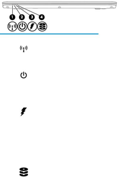
Front
Component |
|
Description |
|
|
|
|
|
(1) |
Wireless light |
On: An integrated wireless device, such as a wireless local |
|
|
|
area network (WLAN) device and/or a Bluetooth® device, is |
|
|
|
on. |
|
|
|
NOTE: On some models, the wireless light is amber when |
|
|
|
all wireless devices are o . |
|
|
|
|
|
(2) |
Power light |
● |
On: The computer is on. |
|
|
● |
Blinking: The computer is in the Sleep state, a power- |
|
|
|
saving state. The computer shuts o power to the |
|
|
|
display and other unneeded components. |
|
|
● |
The computer is o or in Hibernation. |
|
|
|
Hibernation is a power-saving state that uses the |
|
|
|
least amount of power. |
|
|
|
|
(3) |
Battery light |
When AC power is connected: |
|
|
|
● |
White: The battery charge is greater than 90 percent. |
|
|
● |
Amber: The battery charge is from 0 to 90 percent. |
|
|
● |
The battery is not charging. |
When AC power is disconnected (battery not charging):
|
|
● |
Blinking amber: The battery has reached a low |
|
|
|
battery level. When the battery has reached a critical |
|
|
|
battery level, the battery light begins blinking |
|
|
|
rapidly. |
|
|
● |
The battery is not charging. |
|
|
|
|
(4) |
Drive light |
● |
Blinking white: The hard drive is being accessed. |
|
|
● |
Amber: HP 3D DriveGuard has temporarily parked the |
|
|
|
hard drive. |
|
|
|
|
Locating system information
Important system information is located on the bottom edge of the tablet or on the keyboard base. You may need the information when travelling internationally or when you contact support:
(1): Serial number
(2): Product number
(3): Model number
(4): Warranty period
20 Chapter 2 External component identi cation
Loading...