

Page 1
Page 2

Page 3

HP Designjet Z5200ps GP Photo Printer Service Manual
Page 4

For HP Internal Use Only
©Copyright Hewlett-Packard Company 2010
This document contains proprietary
information that is protected by copyright. All
rights are reserved. No part of this document
may be photocopied, reproduced, or
translated to another language without the
prior written consent of Hewlett-Packard
Company.
First Edition, May 2010
Page 5

Notices
Warranty
The information contained in this
document is subject to change without
notice.
Hewlett-Packard makes no warranty
of any kind with regard to this
material, including, but not limited to,
the implied warranties of
merchantability and fitness for a
particular purpose.
Hewlett-Packard shall not be liable for
errors contained herein or for incidental
or consequential damages in connection
with the furnishing, performance, or use
of this material.
WARNING! The procedures described
in this manual are to be performed by
HP-qualified service personnel only.
Electrical Shock Hazard
Serious shock hazard leading to death or
injury may result if you do not take the
following precautions:
Ensure that the ac power outlet
●
(mains) has a protective earth
(ground) terminal.
Disconnect the Printer from the
●
power source prior to performing
any maintenance.
Prevent water or any other liquids
●
from running onto electrical
components or circuits, or through
openings in the enclosure.
Electrostatic Discharge
Refer to the beginning of
Menu on page 73 of this manual, for
precautions you should take to prevent
damage to the Printer circuits from
electrostatic discharge.
Diagnostic
WARNING! The Warning symbol calls
attention to a procedure, practice, or the
like, which, if not correctly performed or
adhered to, could result in personal
injury. Do not proceed beyond a Warning
symbol until the indicated conditions are
fully understood and met.
CAUTION: The Caution symbol calls
attention to an operating procedure,
practice, or the like, which, if not correctly
performed or adhered to, could result in
damage to or destruction of part or all of
the product. Do not proceed beyond a
Caution symbol until the indicated
conditions are fully understood and met.
Content Management Department,
Barcelona Division,
Hewlett-Packard Espanola, S.A.
Avda. Graells, 501
08190 Sant Cugat del Valles
Spain
Safety Symbols
General definitions of safety symbols are
given immediately after the table of
contents.
ENWW iii
Page 6

iv Notices ENWW
Page 7

Using this Manual
Purpose
This Service Manual contains information necessary to test, calibrate and service:
HP Designjet Z5200 Photo Printer 44 inch (Model CQ 11 3A)
●
For information about using this product, refer to the corre sponding User a nd Quick Reference Gui des.
Readership
The procedures described in this Service Manual are to be performed by HP Certified service personnel
only.
Part Numbers
Part Numbers for Printer options, accessories and service parts are located in
on page 151.
Conventions
A small arrow
related to the topic you are consulting.
indicates a link to other parts of the Service Manual where you can find in fo rmation
Parts and Diagrams
ENWW v
Page 8

vi Using this Manual ENWW
Page 9

Table of contents
1 Ink Supplies Troubleshooting & Print Quality
Introduction ..................................................................... .................................... .................................. 2
Troubleshooting System Error Codes .................................................................................................. 2
Performing a Service Test on a failed Assembly ..................................... ................................... .......... 2
Performing the Necessary Service Calibrations ................................................................................... 2
Solving Ink Supplies Problems .................................. .. ..... ..... .. ..... ..... .. ..... ..... .. ..... ..... .. ..... ..... .. ............. 3
Solving Print Quality Problems ................................................ ............................. ................................ 3
Using the Front Panel ......................................................................... .................................................. 3
The Printer does not Power ON ........................................................................................................... 4
The Printer Continuously Rejects Printheads ........................... ................................... ......................... 4
What to do if the Front Panel is blank .................................................................................................. 5
Cover Sensors are not Working ........................................................................................................... 6
The Line Sensor has Problems Detecting Media ................................................................................. 6
Problems with Color Accuracy ............................................................................................................. 6
Troubleshooting Media Jams/Printhead Crashes ................................................................................ 6
Banding at variable extreme environmental conditions ........................................................................ 7
Worm marks on HP Coated media with light area fills ......................................................................... 7
Solving Media-Handling Problems ....................................................................................................... 7
What to do when plastic parts on the Media Basket become damaged during printer setup ............... 8
Solving Ink Supplies problems ............................................................................................................. 9
Ink Cartridges ...................................................................................................................... 9
Available Ink Cartridges ..................... ... .......................... ........................... .......................... 9
Printheads .......................................................................................................................... 10
Available Printheads .......................................................................................................... 10
General Information About the Ink Supplies ...................................................................... 10
General Precautions When Handling Ink Supplies ............................................................ 11
When Should You Replace the Ink Supplies? ................................................................... 11
Ink Cartridge Levels, Information, and Replacement ......................................................................... 11
Ink Cartridge Levels ............................ .... ... .... ..... .. ..... .... ... .... .... ... .... ..... .. ..... .... ... .... ..... .. .... 11
Obtaining Ink Cartridge Information ....................... .. .......................... ......................... ....... 12
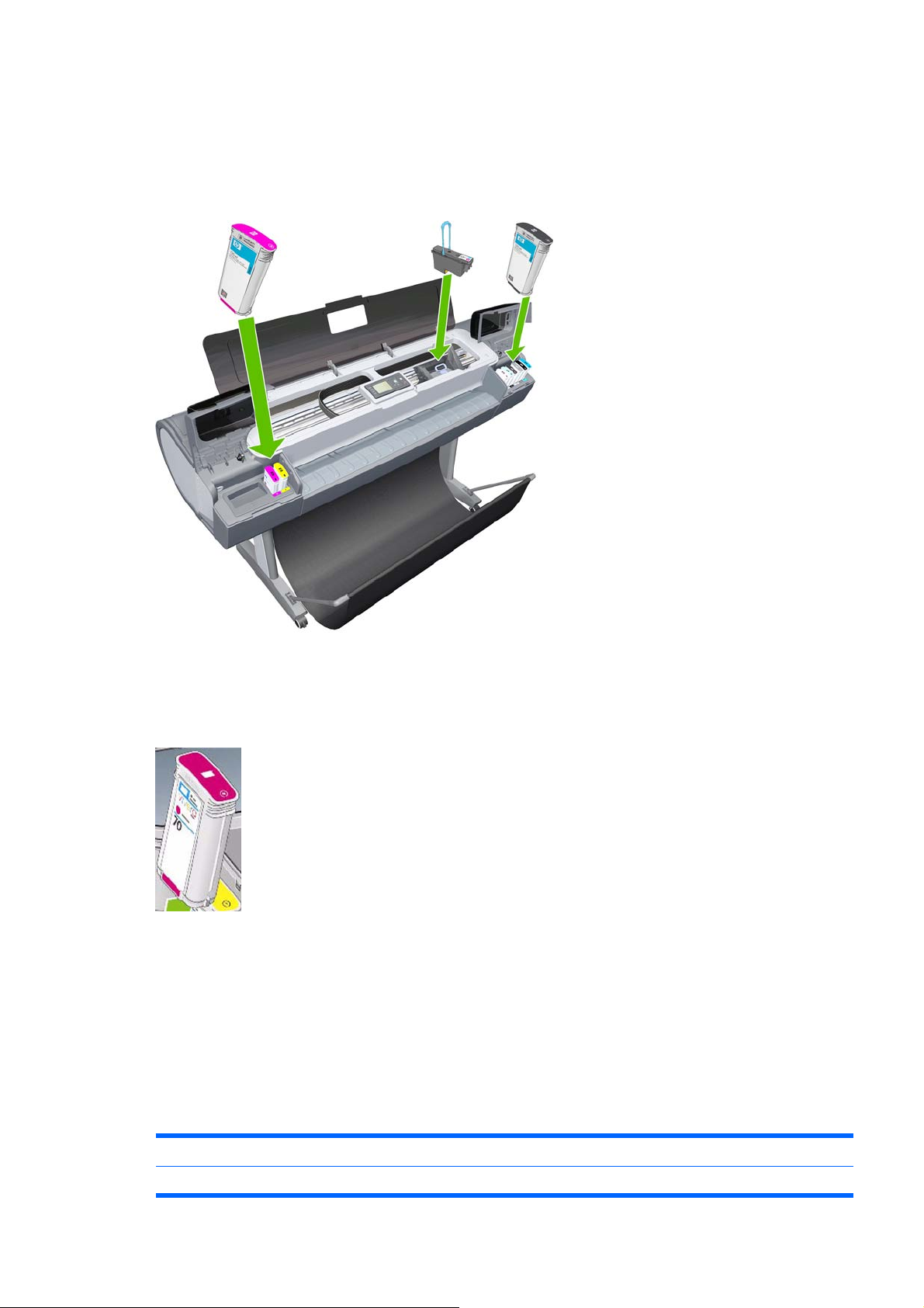
Changing an Ink Cartridge .......................... ........................... ........................... ................. 13
Printhead Information, Replacement and Alignment ................................................................ .......... 15
Obtaining Printhead Information ........................................................................................ 15
Changing a Printhead ........................................................................................................ 16
Aligning Printheads ................................. ..... ....... ....... ..... ....... ....... .... ........ ...... .... ....... ........ 18
Ink Cartridge and Printhead Status Messages ................ .. ............................ ........................... .......... 20
Ink Cartridge Status Messages ............................................................... ........................... 20
ENWW vii
Page 10

Printhead status messages ............................................................................................... 20
Solving Ink Supplies Problems ............................... ...... . ..... ..... .. ..... ..... .. ..... ..... .. ..... ..... .. ..... ..... ....... ... . 21
You Cannot Insert the Ink Cartridge Into the Printer .................................. ........................ 21
You Cannot Insert the Printhead Into the Printer ............................................................... 21
The front panel says to reset or replace a printhead ......................................................... 21
Maintaining and Cleaning the Printheads ................................................................ ........................... 22
Clean the printheads .......................................... ... ....... ..... ... ..... ....... .. ...... ..... .... ...... ..... .... .. 22
Flex Contacts Cleaning Tool ............................... ... .................................. .......................... 22
Print Quality ................................... .. ..... ..... ... ..... ...... . ..... ...... ... ..... ..... .. ..... ..... .. ..... ..... .......................... 23
Print Quality Troubleshooting Actions ........................................................ ........................ 23
The Service Image Quality Diagnostic Print ............................................... ............................ ............ 24
What is the Service Image Quality Diagnostic Print? ........................................................ 24
Considerations for Printing the Diagnostic Print ................................................................ 24
Printing the Diagnostic Print .............................................................................................. 24
Reading the Diagnostic Print Results ........................ ............................ ............................. ................ 25
Diagnostic Part 1: Printhead Reliability ......................................................... ..................... 25
Diagnostic Part 2: Printhead Alignment ............................................................................. 26
Diagnostic Part 3: Printheads & Paper Advance ............................................................... 28
No Printing Defects Found in the Diagnostic Print ................................ ............................. 29
The Advanced Diagnostic Prints ........................................................................................................ 29
What are the Advanced Diagnostic Prints? ....................................................................... 29
Printing the Advanced Diagnostics Print .............................................................. .............. 30
Reading the Advanced diagnostic Print Results ................................................................................ 30
Paper Advance .................................................................................................................. 30
Printhead Alignment .......................................................................................................... 33
Nozzle Health .................................................................................................................... 34
Force Drop Detection .......................................... .... ..... ...... .. ....... ..... ... ..... ....... .. ...... ..... .... .. 35
Troubleshooting Print Quality Problems .............................. ... .... .... .... ... ..... ... .... ..... .. ..... ..... .. ..... ......... 36
Print Quality General Advice .............................................................................................. 36
Horizontal Lines Across the Image (Banding) ................................................................... 36
Lines are Missing, Too Thin, or Too Thick ................................ ... ................................ ...... 37
Problems with Stepped Lines ............................................................................................ 37
Lines are Printed Double or in Wrong Colors .................................................................... 38
Lines are discontinuous ..................................................................................................... 38
Lines are Blurred (Ink Bleeds from Lines) ......................................................................... 39
Problems with Graininess .................................................................................................. 39
Paper is not Flat ................................................................... ................................... ........... 40
Print Scuffing or Scratching when Touched .............................. ..... ... ..... ..... .... ..... ...... .. ...... 41
Ink marks on the paper ...................................................................................................... 41
Problems with the Edges of objects ................................ .................................. ................. 42
Bronzing ............................................................................................................................. 42
Black and white prints do not look neutral ......................................................................... 43
Horizontal lines at the end of a cut sheet print ............................ .. ................................. .... 43
Vertical lines of different colors ................................................... .......................... ............. 43
White spots on the print ..................................................................................................... 43
Problems with Color Accuracy ................................................. .......................... ................ 43
Output Only Contains a Partial Print ................... .......................... .......................... ........... 44
viii ENWW
Page 11

Problems with Image Clipping ........................................................................................... 44
Some objects are missing from the printed image ......................................... ... ... .............. 45
A PDF file is clipped or objects are missing ................................................................. ...... 45
2 System Error Codes
Introduction ..................................................................... .................................... ................................ 46
Continuable and Non-Continu abl e Erro r Codes ................................................................................. 47
System Error Code Brief Descriptions ................................................................................................ 47
System Error Codes - Full Descriptions ............................................................................................. 50
3 Diagnostic Menu
Introduction ..................................................................... .................................... ................................ 74
Diagnostics - Self Test .................. .. ........................... ........................... ............................ . 74
Service Tests (Diagnostics) ................................ ... ....... ...... .. ....... ....... . ....... ....... . ....... ....... .. ............. .. . 74
Entering the Service Tests Menu ............................................................. .......................... 76
.......................................................................................................................................................... 123
1. Scan Axis ...................................................................................................... 76
2. Paper Drive .................................................................................... ............... 87
3. Electronics Module .......................................... ........................ ...................... 90
4. Carriage Assembly ........................................... ......................... .................... 95
5. Sensors ....................................................................................................... 101
6. Color Sensor (ESP) ............................ .. . .. .. .......................... .. .. . .. . .. .............. 104
7. Ink Delivery System (IDS) ........................................................................... 106
8. Service Station ............................................................................................ 110
9. I/O Information .................................................................... ........................ 117
10. Unit Information ......................................................................................... 117
11. EEROM Reset ........................................................................................... 119
12. Set Unit Configuration ............................................................................... 120
13. Error 71:19 Recovery ................................................................................ 120
4 Service Menu
Entering the Service Utilities Menu .................................................................................................. 124
Introduction ...................................................................................................................... 125
......................................................................................................................... 126
1. Turn Drive Roller .......................................................................................................... 126
2. Purge Tubes ................................................................................................................ 128
3. Set SN ......................................................................................................................... 130
4. Reset Life Counters ..................................................................................................... 131
5. Diagnostic Print ............................................................................................................ 132
6. Set Date and Time ....................................................................................................... 132
7. Enable/Disable Firewall ............................................................................................... 133
8. Enable/Disable Sleep Mode ........................................................................................ 134
9. SNMP Language Write Access ................................................................................... 135
10 Borderless Cut Distance ............................................................................................. 137
Service Calibrations ......................................................................................................................... 138
Entering the Service Calibrations Menu .......................................................................... 139
ENWW ix
Page 12

Scan Axis Calibration ....................................................................................................... 139
Service Station Calibration .............................................................................................. 140
Paper Advance Calibration .............................................................................................. 140
Drop Detector Calibration ................................................................................................ 145
Line Sensor Calibration ................................................................................................... 146
Carriage PCA .................................... ...... ..... .... ..... ....... . ....... ..... ... ..... ....... ... ...... ..... ... ....... 149
Color Sensor (ESP) Calibration ............................... ...... ... ... ...... ... ..... .... ... ..... .... ... ...... ... .. 149
5 Parts and Diagrams
Printer Support ................................................................................................................................. 152
Center Covers (Front) ...................................................................................................................... 153
Center Covers (Rear) ................... .. ......................... ........................ ......................... ........................ 154
Right Cover ...................................................................................................................................... 155
Left Cover ............................................................ ............................... .............................................. 156
Right Hand Assemblies ..................... ........................ .......................... ........................ ..................... 157
Left Hand Assemblies ...................................................................................................................... 158
Carriage Assembly .......................... .... ..... . .... ..... .. .... .... .. .... ..... . ..... .... .. ..... ... .. ..... .... .. ..... ... ............. ... 159
Scan-Axis Assemblies ............................... .... ........ ....... ..... ....... ........ .... ........ ....... ..... ....... ................. 160
Paper Path Assemblies (Front) ........................................................................................................ 161
Paper Path Assemblies (Rear) ................................ ..... ... .... ..... ... .... ..... ... .... .... .... .... .... .... .... .... ......... 162
Tools 1 ........................................................................ .................................... .................................. 163
Tools 2 ........................................................................ .................................... .................................. 164
Miscellaneous Parts ......................................................................................................................... 165
6 Removal and Installation
Introduction ....................................................................................................................................... 169
Safety Precautions ....................................... .. ....... ..... ... ..... ....... .. ...... ...... ... ..... ....... . ....... .. 169
Electrostatic Discharge (ESD) Precautions ..................................................................... 169
Required Tools ................................................................................................................ 169
Service Calibration Guide to Removal and Installation .................................................................... 170
Using the Service Calibration Guide ........................ .......................... ......................... ..... 170
The Service Calibration Matrix ................................ ................................ ......................... 171
Performing the Service Calibrations and Diagnostic Tests ............................. .. ............... 172
Window ............................................................................................................................................. 174
Front Cover ...................................................................................................................................... 177
Media Output Assembly ................................................................................................................... 178
Right Front Trim ............................................................................................................................... 179
Left Front Trim ......................................................... .............................. ........................................... 181
Right Ink Cartridge Door ................................................................................................................... 182
Left Ink Cartridge Door .............................................. ......................... ......................... ..................... 183
Right Cover ...................................................................................................................................... 185
Left Cover ............................................................ ............................... .............................................. 188
Rear Tray ......................................................................................................................................... 194
Rear Cover .......................... ..... .... ... .... .... ... ... ..... .. .... ..... . ..... .... .. ..... .... ... ... ..... .. .... ..... . ........... ............ 195
Media Lever ................................... ..................................... ..................................... ......................... 196
Media Lever Position Sensor ........................................................................................................... 198
x ENWW
Page 13

Cutter Assembly ............................ .. ..... ... ... .... .... .. .... .... ... .... .... ... ... ..... .. ... ...... . .... ..... .. .... ................... 199
Right Rear Tray Support .................................................................................................................. 200
Left Rear Tray Support ..................................................................................................................... 201
Front Panel ....................................................................................................................................... 203
Top Cover .............................. .. ..... .... .. .... ..... .. .... .... .. ..... .... ... .... .... .. .... ..... .. ..... ... ... .... .... ......... ... ......... 205
Window Position Sensor .................................................................................................................. 208
Ink Supply Tubes Support Rail ......................................................................................................... 209
Service Station ................................................................................................................................. 214
Drop Detector ................................................................................................................................... 217
Aerosol Fan Assembly ..................................................................................................................... 219
PrintMech PCA ................................................................................................................................. 220
Pen to Paper Space (PPS) Solenoid ................................................................................................ 221
Spindle ..................... .......................................................... .............................................................. 223
Left Spindle Holder ........................................................................................................................... 224
Right Spindle Holder ........................................................................................................................ 224
Clean Out Assembly ................................................ ........................ .......................... ....................... 225
Out Of Paper Sensor ...................................................................................... .................................. 226
Left Roll Guide ......................... .. .......................... ......................... ......................... ........................... 229
Right Roll Guide ............................................................................................................................... 230
Encoder Strip (with spring and attachment nut) ............................................................................... 231
Clean Encoder Strip Procedure .............................................. ....................... ........................ ........... 234
Encoder Strip ................................................ ......................... .......................... ................................. 236
Trailing Cable ................................................................................................................................... 237
Carriage Assembly (with or without Trailing Cable) ......................................................................... 244
Carriage Rear Bushing ..................................................................................................................... 254
Belt Assembly ............................ .. .... ..... .. .... .... .. ..... .... . ..... .... .. ..... .... .. .... ..... .. .... ..... . .... ......... .............. 256
Scan-Axis Motor ............................................................................................................................... 257
Carriage Rail Oiler ............................................................................................................................ 260
Color Sensor (ESP) ......................... . .... .... . .... .... .. ... .... .. ... .... .. ... .... .. .... ... .. ... .... .. ... .... . .... ... .. ............... 262
Line Sensor ...................................................................................................................................... 267
Carriage Cover (includes Carriage Latch) ........................................................................................ 272
Carriage PCA ................................................................................................................................... 276
Right Ink Supply Station ................................................................................................................... 280
Left Ink Supply Station ..................................................................................................................... 284
Ink Supply Tubes ................................................. ......................... ......................... ........................... 288
Formatter ............................................................. ................................................... .......................... 296
Hard Disk Drive .................................... ..................................................... ....................................... 297
Electronics Module (Main PCA and PSU) ........................................................................................ 298
Starwheel Assembly ......................................................................................................................... 301
Print Zone Overdrive ........................................................................................................................ 302
Left Spittoon ..................................................................................................................................... 306
Encoder Disk and Encoder Sensor .................................................................................................. 308
Media Advance Drive ....................................................................................................................... 311
Pinchwheel Assembly ...................................................................................................................... 314
Pinch Roller .....................................................................................................................
Left Starwheel Lifter ......................................................................................................................... 320
Right Starwheel Lifter ....................................................................................................................... 322
................. 319
ENWW xi
Page 14

Starwheel Motor ............................................................................................................................... 325
Full Bleed Foam ............................................................ ............................. ...................................... 326
7 Preventive Maintenance
Preventive Maintenance ................................... .. ..... ..... .. ..... ..... ... .... ..... ... ..... ..... .. ..... ..... .. ..... ............ 328
Moisture on the Printer .................................................................................................... 328
Noisy Carriage Bushing .................................... ....... ..... ... ..... ....... .. ...... ...... ... ..... ..... ... ...... 328
Belt Swelling ................................ .. ..... ..... . ...... ..... . ...... . ..... ..... .. ..... ..... .. ..... .... ... .... ..... ... .... 328
Cleaning the Printer ............................. ... ................................... .................................. .... 328
Carriage Assembly Lubrication ...................... ..... .... .. ..... ... ... .... ..... .. .... ..... . ..... .... .. ..... .... ... 328
General Cleaning ........................... ..... .... ... ..... ... ..... ... .... ..... .. ..... ..... .. ..... .... ... .... ..... .. .... .... 329
Cleaning the Drive Roller and Overdrive ............................. ............................. .. .. ........... 329
Level of Printer Usage ..................................................................................................... 329
Preventive Maintenance Kits .......................... ... ............................. ............................. ..................... 330
Preventive Maintenance Kit #1 ........................ ... .................................. ........................... 330
Preventive Maintenance Kit #2 ........................ ... .................................. ........................... 331
8 Printer menu Map
xii ENWW
Page 15

1 Ink Supplies Troubleshooting & Print
Quality
Introduction
●
Troubleshooting System Error Codes
●
Performing a Service Test on a failed Assembly
●
Performing the Necessary Service Calibrations
●
Solving Ink Supplies Problems
●
Solving Print Quality Problems
●
Using the Front Panel
●
The Printer does not Power ON
●
The Printer Continuously Rejects Printheads
●
What to do if the Front Panel is blank
●
Cover Sensors are not Working
●
The Line Sensor has Problems Detecting Media
●
Problems with Color Accuracy
●
Troubleshooting Media Jams/Printhead Crashes
●
Banding at variable extreme environmental conditions
●
Worm marks on HP Coated media with light area fills
●
Solving Media-Handling Problems
●
What to do when plastic parts on the Media Basket become damaged during printer setup
●
Solving Ink Supplies problems
●
Ink Cartridge Levels, Information, and Replacement
●
Printhead Information, Replacement and Alignment
●
Ink Cartridge and Printhead Status Messages
●
Solving Ink Supplies Problems
●
Maintaining and Cleaning the Printheads
●
Print Quality
●
The Service Image Quality Diagnostic Print
●
ENWW 1
Page 16

Reading the Diagnostic Print Results
●
The Advanced Diagnostic Prints
●
Reading the Advanced diagnostic Print Results
●
Troubleshooting Print Quality Problems
●
Introduction
This chapter will guide you through the relevant steps to take when troubleshooting the printer.
Troubleshooting System Error Codes
Chapter 2, System Error Codes on page 46 contains a list of system error codes and their respective
descriptions and recommended corrective actions. Only try one recommended action at a time and
check if the error code has disappeared.
If you have an error code which is not documented in this Service Manual or you have an error which
you cannot resolve, then report the error to the HP Response Center or the nearest HP Support Office.
When reporting the error, have the following information ready:
Model and Serial Number of the printer
●
Which firmware revision the printer is using (See Note below). Check firmware in Utilities/
●
Statistics/Code rev.
The complete error number (See Note below).
●
The Service Configuration Print.
●
The Current configuration sheet.
●
Which software application the customer is using (name, version, etc.).
●
NOTE: When reporting the System Error Code, make sure that you supply the full Error Code
and the firmware version. Without this information, HP Support Personnel cannot help you.
Performing a Service Test on a failed Assembly
If possible, always perform a Service Test on the component/assembly that you are about to replace,
just to make sure that is the component/assembly that has failed.
NOTE: If the test on that component/assembly passes, you should NOT replace it.
For information on the Service Tests and how to use them see Diagnostic Menu on page 73 & Service
Menu on page 124.
Performing the Necessary Service Calibrations
Is the printer calibrated correctly after replacing a component? For information on the Service
Calibrations and how to use them see Chapter 5, Service Calibrations.
NOTE: Remember that certain Calibrations are required even if an Assembly has been
disassembled to gain access to another Assembly or Component.
2 Chapter 1 Ink Supplies Troubleshooting & Print Quality ENWW
Page 17
Solving Ink Supplies Problems
For information on solving Ink Supplies problems see Solving Ink Supplies problems on page 9 in
this section.
Solving Print Quality Problems
For information on solving Print Quality problems see Print Quality on page 23 in this section.
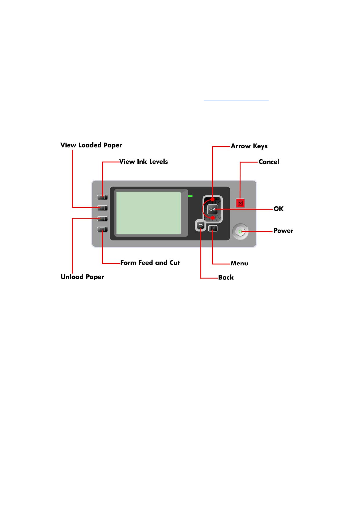
Using the Front Panel
Below is a diagram of the front panel.
Key Function
Arrow Keys
●
Use the Arrow keys to scroll through a menu or toggle between YES or NO when prompted.
Cancel
●
Use the Cancel key to abort or stop a procedure or reject test results.
OK
●
Use the OK key to select a menu option.
Power
●
Use the Power key to turn the printer ON and OFF.
Menu
●
Use the Menu key to enter the main menu.
Back
●
Use the Back key to go back to the previous menu or reject test results.
ENWW Solving Ink Supplies Problems 3
Page 18

Service Key Combinations
Diagnostic mode
●
With the printer OFF, press and hold the UP and OK keys. While hol ding the Up and OK keys down,
press and hold the Power key to turn on the printer. Hold all three keys until the Power key stops
flashing, usually about 5 seconds.
Service Menu (Service Engineers Only)
●
From the main menu, press and hold the Up and Cancel keys.
Service Menu (For users)
●
From the main menu, press and hold the Down and Cancel keys.
The Printer does not Power ON
1. Check that the power cord is connected correctly to the Printer and to the Power Socket.
2. Check that the Power Switch on the BACK of the Printer is in the ON position.
3. Check to see the LED on the Front Panel Power Switch are On.
4. Check that the Front-Panel Cable is correctly connected to the Electronics Module. Also make sure
that the Front-Panel cable is not damaged.
5. Replace the Power Supply Unit
Refer Electronics Module (Main PCA and PSU) on page 298.
The Printer Continuously Rejects Printheads
1. Clean the flex contacts on the Printhead and in the Carriage Assembly using the Carriage
Interconnect Wiper (Refer to
2. If ALL the Printheads are rejected (the status message on th e F ron t Pa ne l do es NOT show "OK"
for ALL the Printheads) then perform the Electronic Module Test
on page 90.
Flex Contacts Cleaning Tool on page 22) and try again.
Refer 3. Electronics Module
4 Chapter 1 Ink Supplies Troubleshooting & Print Quality ENWW
Page 19
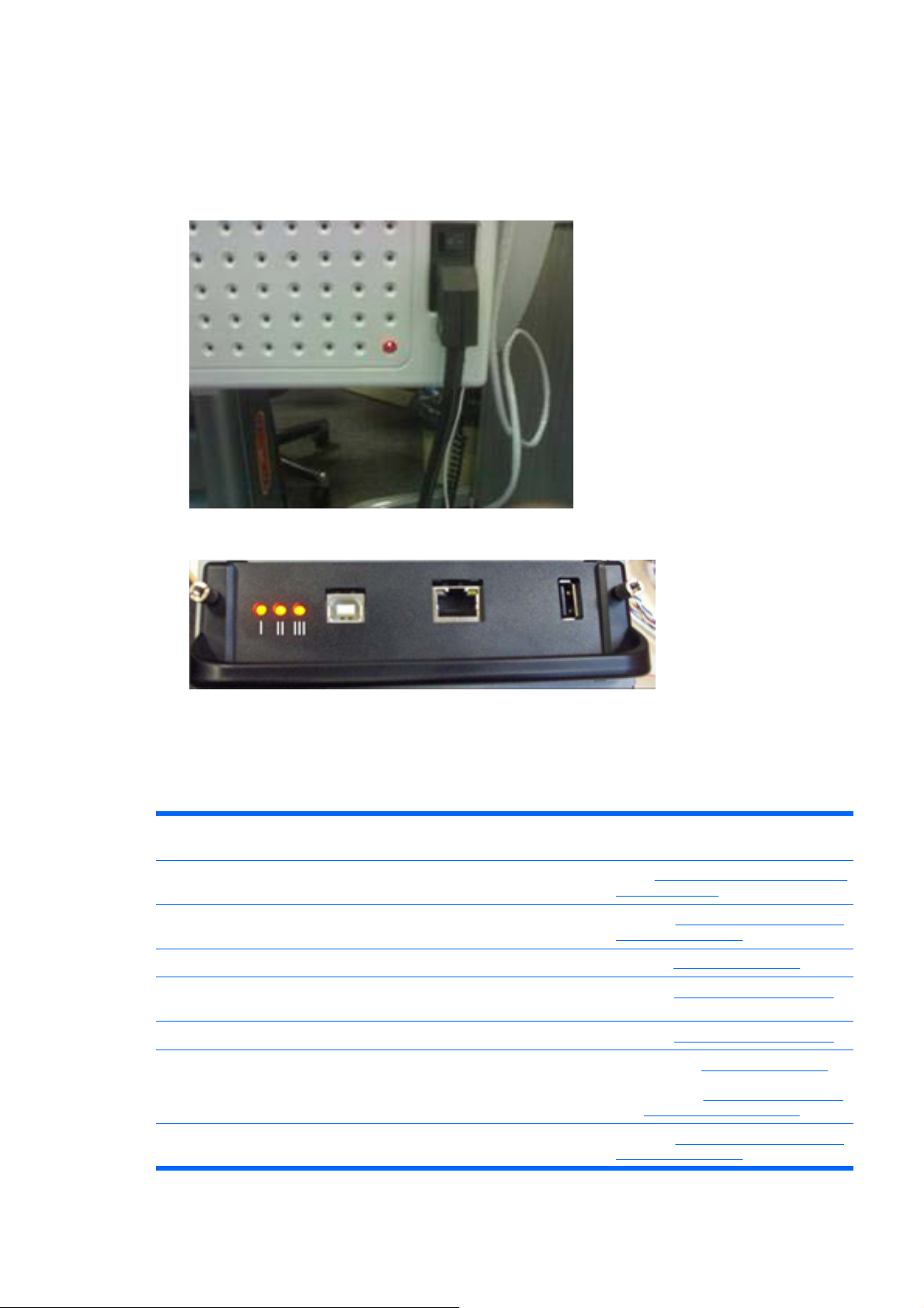
What to do if the Front Panel is blank
The LEDs of the formatter (visible through the cover) and the power supply can help you troubleshoot
a problem when the Front Panel is blank.
1. The following image shows the Power Supply LED, looking through the cover.
2. The following image shows the Formatter LEDs, which are marked I, II and III.
Use the following table to interpret the LEDs and find the so urce of the problem. Remember that
▲
you should read these LEDs when you push the Power button. Some combinations may require
the replacement of two or more components. In th is case, always replace one component at a time.
Test the printer to see if the problem has disappeared (ch eck the LEDs again). If the same LED
sequence continues, replace the next component indicated in the table.
Power
Supply LED
1 Off Off Off Off Off Power Electronics Module (Main PCA and
2 On Off Off Off Off Main PCA Electronics Module (Main PCA
3 On On Off N/A N/A Formatter Formatter on page 296
4 On On
5 On On On (flashing) Off N/A Hard Disk Hard Disk Drive on page 297
6 On On On Off N/A 1. Formatter Formatter on page 296
7 On On On On (flashing) N/A Main PCA Electronics Module (Main PCA
Formatter
LED 1
(Flashing)
Formatter
LED 2
Off Off N/A Hard Disk Hard Disk Drive on page 297
Formatter
LED 3
Front Panel
Status
Solution (part replacement)
PSU) on page 298
and PSU) on page 298
2. Main PCA
PCA and PSU) on page 298
and PSU) on page 298
Electronics Module (Main
ENWW What to do if the Front Panel is blank 5
Page 20

8 On On On On Front Panel
(Light on)
1. Front Panel Front Panel
on page 203
2. Formatter
3. Main PCA
PCA and PSU) on page 298
4. Front Panel Cable
on page 203
9 On On On On Off Front Panel Front Panel on page 203
Formatter on page 296
Cover Sensors are not Working
1. Perform the Sensors Test Refer 5. Sensors on page 101.
2. Check if the cable for the faulty sensor is not damaged and is connected correctly.
3. Replace the faulty Sensor.
The Line Sensor has Problems Detecting Media
1. Check the type of media that is being used since the Line sensor may have problems detecting
transparent media or some types of Non-HP media. Try loading white HP media in to the Printer
and check if the Line sensor detects it.
2. The Line Sensor is not calibrated correctly. Perform the Line Sensor Calibration
Sensor Calibration on page 146.
Electronics Module (Main
Front Panel
Refer Line
3. The Line Sensor is damaged or faulty. Replace the Line Sensor
Line Sensor on page 267.
Problems with Color Accuracy
The Color Sensor (ESP) is a powerful tool unique to the Z series printers to maintain color accuracy. If
you notice any problems with colors, perform the Color Sensor (ESP) calibration. Refer to
(ESP) Calibration on page 149.
Troubleshooting Media Jams/Printhead Crashes
The failure modes "media jam" and "head crash" are grouped together because in many cases a media
jam causes the media to lift up into the Carriage path and cause a Printhead crash, thus causin g many
media jam failures to be reported as head crashes.
1. Did the media jam occur when loading media?
If the client has had media jams, it is common for pieces of media to get stuck in the media
●
path. Clear the media path.
NOTE: When clearing a media jam, sometimes media is stuck in the paper path. To clear this,
you must lift the Media Lever and insert thicker media into the p ap er pa th t o push ou t th e media
that is still stuck there.
2. Is the customer using non-HP media?
Color Sensor
The use of non-HP media can easily be the cause of media jams and head crashes (espec ially
●
head crashes because HP media is specially formulated to avoid cockle, one of the primary
causes of head crashes). If the media is not HP approved, advise the customer to use HP
media and check to see if the problem is now solved.
6 Chapter 1 Ink Supplies Troubleshooting & Print Quality ENWW
Page 21

Banding at variable extreme environmental conditions
Since the Accuracy Calibration has been done at normal environmental conditio ns, printing in extreme
environmental conditions will cause banding because the advan ce of th e Media Advance Roller does
not correspond to the same conditions that the calibra tio n was done in. To solve the problem, try the
following:
Perform the Accuracy Calibration in the new environmental conditions (Refer to the User’s Guide).
Worm marks on HP Coated media with light area fills
Light bands (S-shaped) in Paper axis direction where light area fills are printed, causing unacceptable
Image Quality defect.
Print the Service Configuration Print and check if the level of Humidity is very low (below 30%).
●
Increasing humidity may help in reducing the severity of th e p ro blem.
NOTE: The media is causing the problem and NOT the Printer. Do not attempt to try and replace
Printer parts to solve this problem.
Solving Media-Handling Problems
The Front Panel indicates that media is misalig ne d or incorrectly positioned.
Roll media
●
●
●
NOTE: Ensure that the paper is wrapped tightly on the roll. This is a very imp ortant step to rememb er
because if this is not done, the media may be loaded at an angle, causing the media to be rejected.
Sheet media
●
●
●
●
●
The roll may be loaded the wrong way. The paper should load over the roll toward you.
Check that the paper is correctly loaded onto the spindle.
The paper may be loaded at an angle. The right-hand edge must be aligned with the blue line on
the Print Platen.
Always load sheet media using the Rear Input Tray. Do NOT load the media as you would load
roll media.
It must be loaded with the right-hand edge against the blu e line on th e Prin t Platen.
The media may be crumpled or warped or may have irregular edges.
If hand-cut media is used, the edges may not form a right-angle or they may be rough. If possible,
hand-cut media should not be used. Only purchased sheet media should be used in the Printer.
If you have problems with paper jams, check that the Overdrive is not obstructed by bits of paper
or using the Turn Drive Roller Service Utility
1. Turn Drive Roller on page 126.
ENWW Banding at variable extreme environmental conditions 7
Page 22
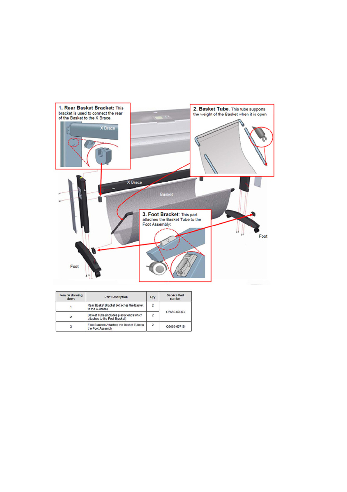
What to do when plastic parts on the Media Basket become damaged during printer setup
The following information explains what to do if one or more of the back plastic brackets or the Basket
Tube becomes broken. The information helps to identify which service parts to order as replacements.
There are three plastic parts that could break during printer installation and need replacing. Use the
pictures below to identify with the customer which part needs replacing (numbers 1, 2 or 3).
8 Chapter 1 Ink Supplies Troubleshooting & Print Quality ENWW
Page 23
Solving Ink Supplies problems
What are Ink Supplies?
For each of the ink colors used in the printer, there are two components, th e Printhead and Ink Cartridge.
These components are called Ink Supplies.
Ink Cartridges
The printer's Ink Cartridges provide ink to the Printheads. The color Ink Cartridges supplied with the
printer have a capacity of 69ml but optional 130 ml and 30 0 ml are also ava ilab l e.
The Ink Cartridges require no maintenance or cleaning. As long as each Ink Cartridge is inserted
correctly into its slot, the ink will flow to the Printheads. Because the Printheads control the amount of
ink transferred to the page, you will continue to see high quality printing results that require no
maintenance or cleaning. As long as each Ink Cartridge is inserted correctly into its slot, the ink will flow
to the Printheads. Because the Printheads control the amount of ink transferred to the page, you will
continue to see high quality printing results even when the ink levels are getting low.
The front panel displays the status of the Ink Cartridge. Using the front panel, detailed information can
be checked on the Ink Cartridges.
Available Ink Cartridges
Color Part number 69ml Part number 130ml Part number 300ml
HP 70 Matte Black C9436A C9448A CN635A
ENWW Solving Ink Supplies problems 9
Page 24
HP 70 Photo Black C9437A C9449A CN633A
HP 70 Light Gray C9439A C9451A CN634A
HP 70 Cyan C9440A C9452A CN636A
HP 70 Magenta C9441A C9453A CN629A
HP 70 Yellow C9442A C9454A CN630A
HP 70 Light Magenta C9443A C9455A CN631A
HP 70 Light Cyan C9389A C9390A CN632A
Printheads
The Printheads are extremely durable an d d o n ot need to be replaced every time an Ink Cartridge is
replaced. They are independent of the Ink Cartridges and will continue giving excellent image quality
results even if the Ink Cartridges are low on ink.
If you notice a decline in print quality such as lines or dots missing from text/graphics, go to
Troubleshooting Print Quality Problems on page 36.
Available Printheads
Printhead Type Part number
HP 70 Matte Black & Cyan C9404A
HP 70 Light Magenta & Light Cyan C9405A
HP 70 Magenta & Yellow C9406A
HP 70 Photo Black & Light Gray C9407A
General Information About the Ink Supplies
For optimum results from the printer and modular ink delivery system always follow these guidelines
when handling the ink supplies:
Always install the Ink Cartridges and Printheads befo re t he exp ira tion da te , wh ich is o n the
●
packaging.
Install Ink Cartridges and Printheads in their color-coded slots.
●
Follow the instructions on the front panel of the Printer during installation.
●
Avoid unnecessary removal of the Ink Cartridges and Printheads.
●
10 Chapter 1 Ink Supplies Troubleshooting & Print Quality ENWW
Page 25

When turning off the Printer always use the power Off button on the front panel. The Printheads
●
are then stored correctly which prevents them from drying out.
The Ink Cartridges should never be removed while the printer is printing. They should only be
●
removed when the printer is ready for you to replace them. The front panel will guide you through
the removal and installation procedure.
General Precautions When Handling Ink Supplies
Use the following precautions when handling Ink Supplies:
NOTE: Do not touch, wipe or attempt to clean the printhead nozzles. This can damage the printhead.
Handle the ink supplies with care. In particular the Printhead, which is a hi gh precision de vice and
●
must be handled carefully.
Do not touch the Printhead nozzles.
●
Do not put the Printhead down on the nozzles.
●
Do not be rough when handling the Printheads. Always set them down gently.
●
Do not drop the Printheads.
●
Proper handling will assure optimum performance throughout the Printhead life.
●
Do not touch the end of the Ink Cartridge which is inserted into the printer as there may be a small
●
amount of ink on the connection.
Avoid storing partially used Ink Cartridges on their ends.
●
When Should You Replace the Ink Supplies?
When to change the ink supplies is mostly determined by you with guidance from the front panel. In
conjunction with the messages displayed in the front panel and the message explanations in this
chapter, you will be able to choose for yourself when is the right time to change the ink supplies.
The Printer will also display the ink level and will tell you when the ink supply is low on ink. This means
you have constantly updated information about the ink supplies.
Ink Cartridge Levels, Information, and Replacement
Ink Cartridge Levels
The front panel displays Ink Levels shown as level bars. These bars represent how much ink is remaining
in the Ink Cartridges: as ink is used up the bars get shorter in length.
There are two methods for checking the ink levels of your Ink Cartridges.
“View Ink Levels” Direct Access Key
Pressing the “View ink levels” direct access key on the Front Panel will immediately show you the
●
ink levels. For more information about direct access keys, refer
Using the Front Panel on page 3.
ENWW Ink Cartridge Levels, Information, and Replacement 11
Page 26
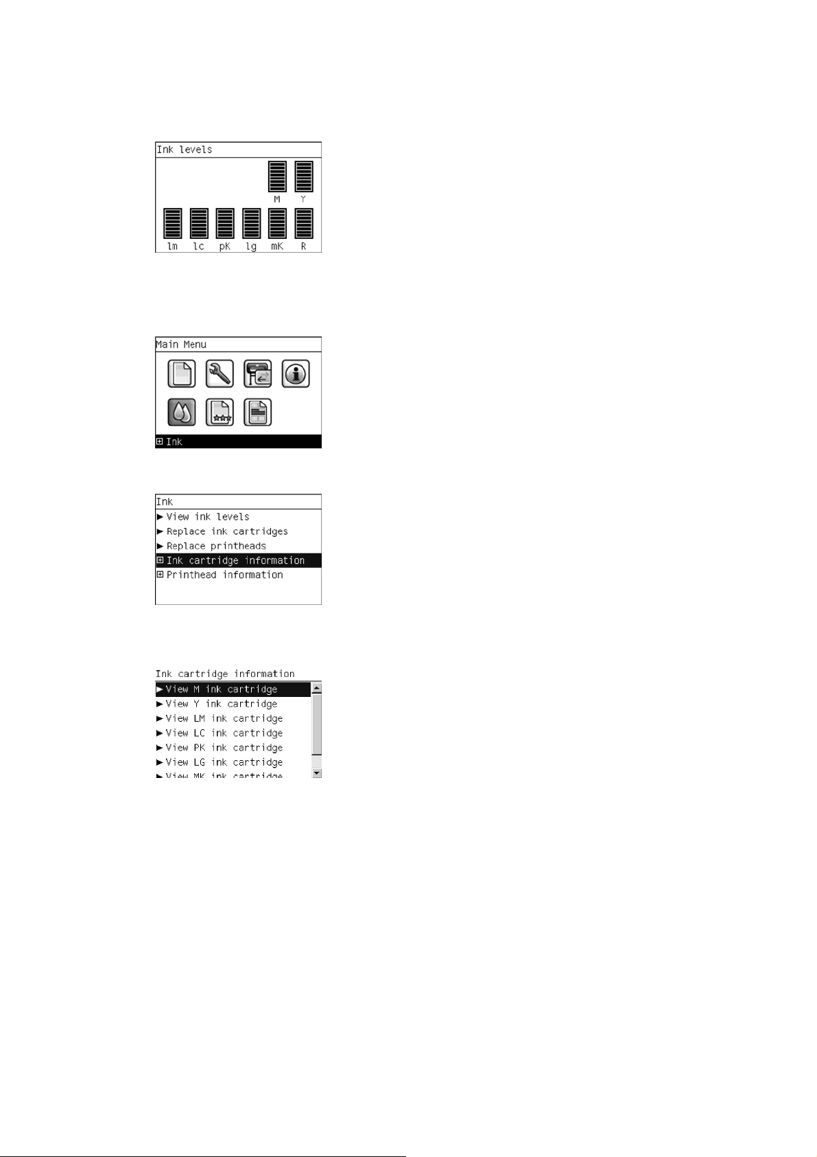
“View Ink Levels” from the ink menu
Choosing the View ink levels options from the Ink menu will immediately show you the ink levels:
●
Obtaining Ink Cartridge Information
1. Scroll to the Ink Menu icon and press OK
2. In the Ink Menu submenu, scroll to Ink cartridge information and press OK
3. In the Ink cartridge information submenu, scroll to the Ink Cartridge that you want information
on and press OK.
12 Chapter 1 Ink Supplies Troubleshooting & Print Quality ENWW
Page 27
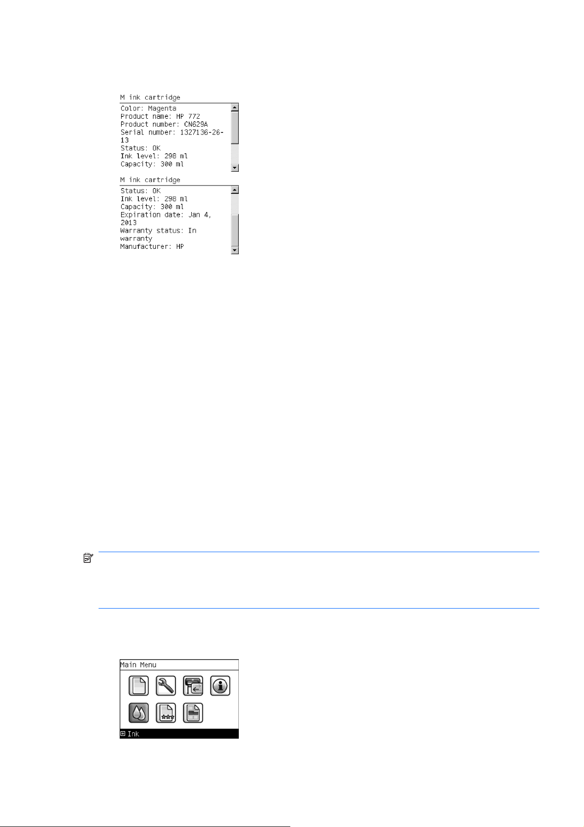
4. The front panel displays information on the selected Ink Cartridge. Use the Arrow keys to scroll
through the information.
The information supplied is:
The make of the Ink Cartridge.
●
The product number of the Ink Cartrid ge .
●
The serial number of the Ink Cartridge.
●
The current status of the Ink Cartridge.
●
The current ink level of the ink cartridge in milliliters.
●
Original capacity of the ink cartridge in milliliters.
●
The manufacturer of the Ink Cartridge (hp is recommended).
●
The current warranty status of the Ink Cartridge.
●
Changing an Ink Cartridge
There are two occasions when you need to remove an ink cartridge:
The ink cartridge is very low and you want to replace it with a full cartridge for unattended printin g
●
(you can use up the remaining ink in the first cartridge at a more convenient time).
The ink cartridge is empty or faulty, and you must replace it to continue printing.
●
NOTE: Do not try to remove an ink cartridge w hile printing. Remove an ink cartridge only if you are
ready to insert another one.
Make sure the printer wheels are locked (the brake lever is pressed down) to prevent the printer from
moving.
Change an ink cartridge using the following procedure:
1. Scroll to the Ink Menu icon and press OK.
ENWW Ink Cartridge Levels, Information, and Replacement 13
Page 28
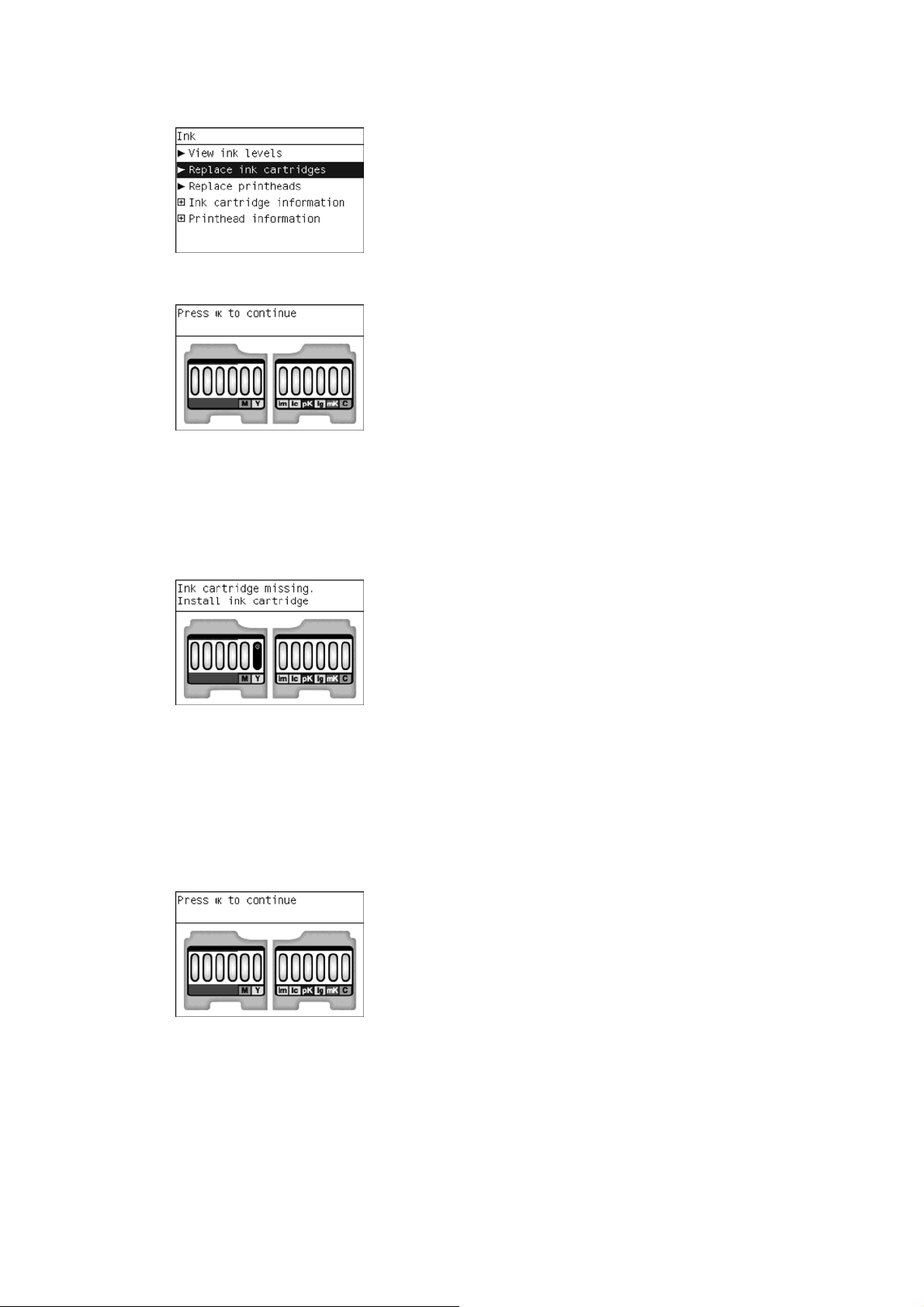
2. In the Ink Menu submenu, scroll to Replace ink cartridges and press OK.
3. The front panel displays the status of the Ink Cartridges.
4. Press OK to continue.
5. Open the relevant Ink Cartridge cover fo r th e Ink Cartridge you want to replace.
6. Pull the required Ink Cartridge straight up to remove it from the printer.
7. The front panel indicates the missing Ink Cartridge.
8. Before removing the cartridge from its wrapping, shake it vigorously.
9. Unwrap the new ink cartridge, find the label identifying the ink color. Check that the letter or letters
marking the empty slot, matches the letter or letters on the cartridge label.
10. Insert the ink cartridge into its slot.
11. Push the cartridge into the slot until it snaps into position. You should hear a beep and see
confirmation that the cartridge has been inserted.
12. When all cartridges have been inserted, close the cover.
14 Chapter 1 Ink Supplies Troubleshooting & Print Quality ENWW
Page 29
Printhead Information, Replacement and Alignment
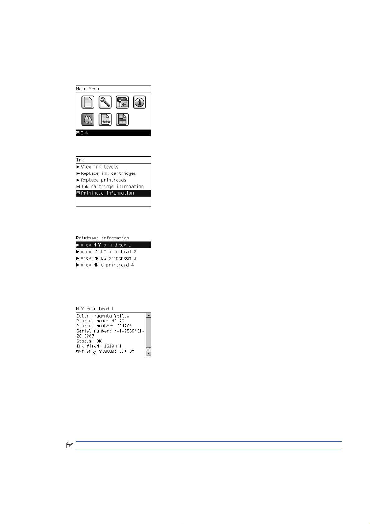
Obtaining Printhead Information
1. Scroll to the Ink Menu icon and press OK.
2. In the Ink Menu submenu, scroll to Printhead information and press OK.
3. In the Printhead Information submenu, scroll to the Printhead that you want information on and
press OK.
4. The front panel displays information on the selected Printhead.
The information supplied is:
The make of the printhead.
●
The product number of the Printhea d.
●
The serial number of the Printhead.
●
The current status of the printhead.
●
How much ink has been fired (consumed) by the printhead.
●
NOTE: It is possible for a printhead to consume more than one Ink Cartridge.
The current warranty status of the Printhead.
●
ENWW Printhead Information, Replacement and Alignment 15
Page 30
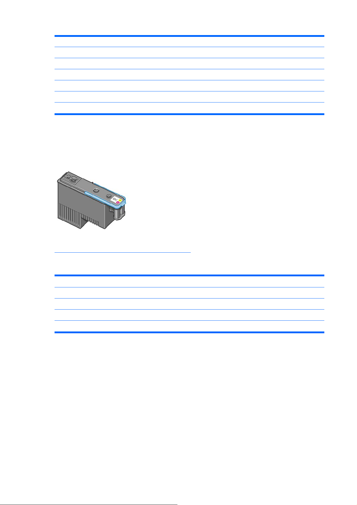
Changing a Printhead
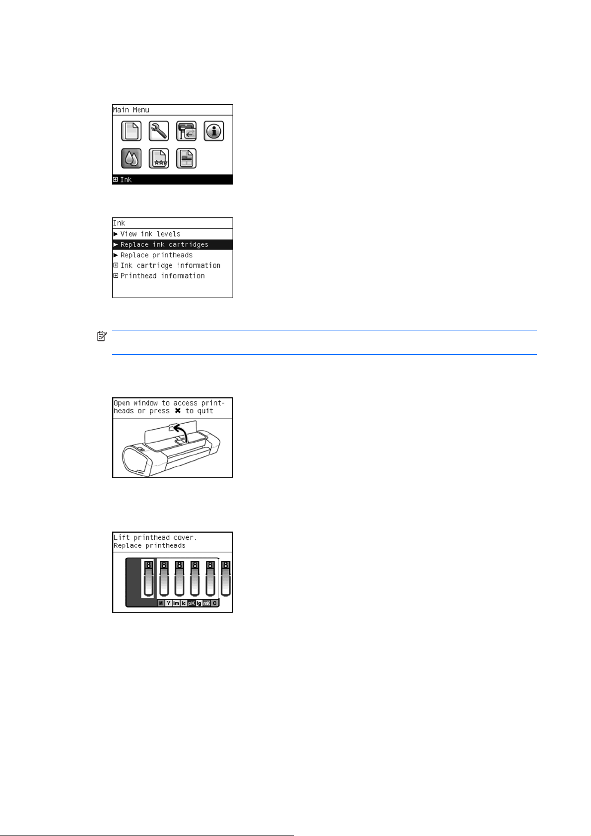
1. Scroll to the Ink Menu icon and press OK.
2. In the Ink Menu submenu, scroll to Replace printheads and pressOK .
3. The printer moves the Carriage to the correct position to replace Printheads.
NOTE: If the carriage is left in the removal position for more than three minutes without inserting
or removing any printheads, it will try to move back to its normal position at the right-hand end.
4. When the carriage has stopped moving, the front panel display will prompt you to open the wi ndow
and lift the carriage cover.
5. Open the window.
6. Lift the Carriage cover to access the printhea d s.
7. Lift the blue handle and pull the Printhead straight up out of the Carriage.
16 Chapter 1 Ink Supplies Troubleshooting & Print Quality ENWW
Page 31

8. To insert a new printhead first remove the or an ge p ro te c tive ca ps.
9. The printhead is designed to prevent you from accidentally inserting it into the wrong slot. Check
that the colored label on the printhead matches the colored label of the carriage slot into which th e
printhead is to be inserted. Insert the printhead slowly and vertically, straight down. It may be
damaged if you insert it too fast, or at an angle, or if you rotate it as you insert it.
10. Insert all other printheads that need to be installed, and close the carriage cover.
11. Close the Window.
12. When all the printheads have been inserted correctly and accepted by the printer, the printer will
beep. If the printer does not beep when you insert the printhead an d the Replace message appears
on the front panel display, the printhead may need to be reinserted.
The front panel display confirms that all printheads are correctly inserted. The printer will start
checking and preparing the printheads. The front panel display confirms that all printheads are
correctly inserted. The printer will start checking and preparing the printheads. The default routine
process, when all printheads are changed, takes 25 minutes. If the printer finds problems in
preparing the printheads, it will take longer, up to 55 minutes. For a single printhead insertion, the
times vary between 15 and 35 minutes. After all printheads are checked and prepared, for the
printhead realignment.
ENWW Printhead Information, Replacement and Alignment 17
Page 32

Aligning Printheads
Precise alignment between printheads is essential for accurate colors, smooth color transitions, and
sharp edges in graphical elements. Your printer has an automatic printhead alignment process which
runs whenever a printhead has been accessed or replaced.
In cases where the paper has jammed, you have used a custom paper, or are experiencing problems
with color accuracy you may need to align the printheads. If the paper has jammed, it is re commende d
that you reinsert the printheads and initiate the realignment procedure with the Image Quality
Maintenance menu.
NOTE: Do not use transparent and semi-transparent paper to align the printheads. Photo paper is
recommended for the best quality.
Reinsert Printheads Procedure
1. If the realignment process is running and the wrong paper is loaded, press the cancel key on the
front panel. Do not print if the realignment process has been canceled. You can restart the
alignment with the Image Quality Maintenance menu procedure.
2. Load the paper you wish to use. You can use a roll or cut sheet.
3. Remove and reinsert all the printheads, see Remove a printhead and Insert a printhead. This will
start the printhead alignment procedure.
4. Ensure the transparent window closed, as a strong light source near the printer during printhead
realignment can affect alignment.
5. The process will take about six minutes. Wait until the front panel display shows the process
complete before using the printer.
Image Quality Maintenance Procedure
1. Load the paper you wish to use. You can use a rol l or cut sheet, however, it must be at le ast a 16
inches roll, or an A2 portrait sheet (420mm x 594mm). Do not use transparent and semi-transparent
paper to align the printheads. Photo paper is recommended for the best results; plain, bond and
thin coated papers provide acceptable but marginal results.
2. Press the Menu key to return to the main menu and select the Image Quality Maintenance menu
icon.
3. Select Alig n printheads. The printer will check to see if it has en ough paper to run the realignment.
18 Chapter 1 Ink Supplies Troubleshooting & Print Quality ENWW
Page 33

4. If the loaded paper is satisfactory, the printer will run the realignment and print a realignment
pattern. Ensure the transparent window is closed, as a strong light source near the printer during
printhead realignment can affect alignment.
Figure 1-1 Z5200 Plot:
5. The process will take about eight minutes. Wait until the front panel display shows the process
complete before using the printer.
Scanning errors during alignment
If the alignment process fails, a Scanning problems message appears on the front panel. This means
that the alignment has not completed successfully. Ther efore the printer is not aligned and the alignment
should be repeated before printing with good image quality. The problem may be due to:
The paper used was not valid, repeat the alignment with valid paper.
●
Printhead health problems, clean printheads.
●
The alignment was done with the transparent window open, repeat th e alignment with the window
●
closed.
If the problem persists after using valid paper, cleaning the printheads, a nd keeping the window closed,
there may be a Failure in the scanning system needing reparation or the printheads, although clean,
may not work and need to be replaced.
ENWW Printhead Information, Replacement and Alignment 19
Page 34

Ink Cartridge and Printhead Status Messages
Ink Cartridge Status Messages
OK The Ink Cartridge is operating correctly and no action is
required.
Missing There is no Ink Cartridge present, or it is not properly
connected to the printer
Low The Low message is an early warning sign and it is advisable
that new supplies should be obtained of that particular color.
The amount of ink remaining in the Ink Cartridge depends on
it’s capacity, but there is approximately 14% of ink available for
the user.
Very Low When theVery Low message is displayed, overnight printing
should not be attempted. Changing the Ink Cartridge is
strongly recommended to prevent the printer from stopping
halfway through a print. There is approximately 8% of ink
available for the user.
Empty The printer will stop and will not be able to continue printing
until a new Ink Cartridge has been installed. If this occurs
halfway through printing an image, you should check the
quality of this image, as stopping mid-plot can affect the print.
It would be recommended to reprint the image once a new Ink
Cartridge has been installed.
Reseat You are recommended to remove the Ink Cartridge and then
Replace You are recommended to replace the Ink Cartridge with a new
Altered There is something unexpected about the Ink Cartridge's
Expired The Ink Cartridge has passed the expiration date.
Printhead status messages
OK The Printhead is operating correctly and no action is required.
Missing There is no Printhead present, or it is not properly connected
Test printhead
separately
Reseat You are recommended to start the printhead removal process
reinsert it.
Ink Cartridge.
status.
to the printer.
You are recommended to test the printheads individually to find
the failing printhead. Remove all the printheads and insert
them alone one by one, Closing the latch and the carriage
cover after every insertion. The front panel display will indicate
the failing one showing the reseat or replace message.
from the front panel, but instead of removing the printhead,
simply press the OK key on the front panel.
Replace You are recommended to remove the printhead and then
reinsert it; if that fails, clean the electrical connections; if that
fails, replace the printhead with a new printhead.
Replacement
incomplete
Remove The printhead is not a suitable type for use in printing (for
A printhead replacement process has not completed
successfully, relaunch the replacement process and let it finish
completely (it is not needed to change the printheads).
instance, a setup printhead).
20 Chapter 1 Ink Supplies Troubleshooting & Print Quality ENWW
Page 35

Solving Ink Supplies Problems
Most of the problems that you could encounter when working with the ink supplies are solved with
guidance from the front panel. A full list of front panel messages are supplied in the User’s Guide.
You Cannot Insert the Ink Cartridge Into the Printer
1. Ensure that you have the correct hp Ink Cartridge.
2. Ensure that the Ink Cartridge is the correct color for that slot.
3. Ensure that the Ink Cartridge is the correct orientation, with the color coded label at the top.
NOTE: Never clean inside the Ink Cartridge slo ts as this can cause damage to the Printer.
You Cannot Insert the Printhead Into the Printer
1. Ensure that you have the correct hp Printhead.
2. Ensure that the printhead is the correct color for that slot.
3. Ensure that the printhead is in the correct orientation.
4. Ensure that the protective cap is removed from the Printhead.
The front panel says to reset or replace a printhead
1. From the front panel, turn the power off then ON.
2. Check the front panel display message, if it shows the ready message, the printer is ready to print.
If the problem remains continue with the next step.
3. Remove the printhead.
4. Clean the electrical connections on the backside of the printhead with a lint free cloth. You can
carefully use a mild rubbing alcohol if moisture is needed to remove residue. Do not use water.
You can use the Flex Contacts Cleaning Tool.
This is a delicate process and may damage the printh ead. Do not touch the n ozzles on the bottom
side of the printhead, especially not with any alcohol.
ENWW Solving Ink Supplies Problems 21
Page 36

5. Reinsert the printhead.
6. Check the front panel display message. If the problem remains, try a new printhead.
Maintaining and Cleaning the Printheads
Clean the printheads
As long as the printer is kept turned on, an automatic cleani ng is pe rfo rme d pe riod ica l ly . T his e n sur es
there is fresh ink in the nozzles and pr eve n t s n o zzle clogs, which ensures color accura cy.
If you have not already done so, please refer to Horizontal lines across the image (banding) and The
Image Diagnostics Print before proceedin g.
To clean the printheads, press the Menu key to return to the main menu and select the Image Quality
Maintenance menu icon, then Clean printheads. If you have gone through the Image Quality Diagnostic
print process, you know which colors are failing. Select to the pair of printheads which contain the failing
colors. If you are not sure which colors to clean, you can also select to clean all printheads.
Cleaning all printheads takes about nine minutes. Cleaning a single pair of printheads takes about six
minutes. Cleaning all printheads uses more ink than cleaning a single pair.
If you have cleaned the printheads using the Clean printheads procedure from the front panel and are
still experiencing image quality problems, you can try cleaning the printhead nozzles ma nually using the
following procedure.
NOTE: This is a delicate process and may damage the printhead. Do not touch the electrical
connections on the backside of the printhead.
You must remove the printhead (see Remove a printhead) and using a cotton swab and a little de-
ionized, distilled water, or Carriage Interconnect Wiper clean the bottom of the printhead until the residue
is removed.
Flex Contacts Cleaning Tool
NOTE: The Flex Contacts Cleaning Tool is part of the Maintenance Tool Kit which can be ordered
using Part Number Q5669- 60690. All the instructions needed to use the Flex Contacts Cleaning Tool
will be packaged with the kit.
Whenever you replace the Printhead, check the empty slots to see if they need cleaning. In extreme
circumstances, when a Printhead is inserted, it is possible that the Printer will not recognize it due to
the build-up of ink on the electrical connection between the Printhead and the Carriage Assembly.
Included with the Printer is a Flex Contacts Cleaning Tool. This tool is provid ed in a sepa rate pa ckage.
It also contains replacement sponges and an instruction sheet. This tool should be used for cleaning
the electrical interconnects of both the Carriage Assembly and the Printhead.
If the front panel displays the message “Reseat” or “Replace” next to the offending printhead, try cleaning
the flex circuits of the Carriage and the Printheads using the Carriage Interconnect Wiper.
22 Chapter 1 Ink Supplies Troubleshooting & Print Quality ENWW
Page 37

NOTE: Do not touch, wipe or attempt to clean the printhead nozzles. This can damage the printhead
and reduce print quality.
Print Quality
Print Quality Troubleshooting Actions
NOTE: Phone support: For some Print Quality problems, a Call Agent can try and troubleshoot the
Printer by requesting the Customer to perform cert ain actions. Using this process, most problems can
resolved without the need of an on-site visit.
When faced with a Print Quality problem, perform the following actions in order to resolve the problem:
1. Printer Configuration:
Check that the paper type loaded corresponds to the paper type selected in the front panel
●
and in the software. You can verify the paper type selected through the Front Panel (Main
Menu/ Paper menu/ View loaded paper).
Make sure that the correct Print Quality settings are used for different types of print content.
●
Dry time should be set to “Optimal”.
●
2. Perform Printhead recovery (Main Menu/Image Quality Maintenance/Clean Printheads).
3. Media:
Select the correct media type through the front panel when loading it.
●
Make sure that HP or HP-approved media is being used.
●
4. Perform the Printhead Alignment (Main Menu/ Image Quality Maintenance/ Align Printheads),
using the same paper type with which you were experiencing unacceptable image quality, if feasible
(some paper types are not suitable for Printhead Alignment).
5. Check if the latest version of the firmware is installed. If not, install the latest firmware revision.
ENWW Print Quality 23
Page 38

The Service Image Quality Diagnostic Print
What is the Service Image Quality Diagnostic Print?
The Printer contains an internal Image Quality Test which helps you to diagnose the possible source of
any image quality defects. The Service IQ Diagnostic Print is available in the following options:
1. Image Quality Service Best Plot. This plot helps you to diagnose in more detail the possible source
of any image quality defects. It is accessible through the Service Utility Menu.
The Image Quality Service Best Plot uses the Best Print Mode and is divided in to three parts as
follows:
Diagnostic Part 1: Printhead Reliability Test. The purpose of this test is to identify which
●
Printhead is faulty.
Diagnostic Part 2: Printhead Alignment Test. This test is designed to check any color-to-color
●
and bi-directional misalignment the printer may ha ve .
Diagnostic Part 3: Printheads and Paper Advance test. This test is designed to check whether
●
the Printheads and the Media Advance Mechanism are working correctly.
2. Image Quality Service Normal Plot. This plot is the same as the Image Quality Service Best Plot
but uses the Normal Print Mode.
3. Advanced Diagnostic Plot. These tests provide more information of the IQ defects that we could
find in the Image Quality Service plot. For more information, refer to
Prints on page 29.
The Advanced Diagnostic
Considerations for Printing the Diagnostic Print
1. The IQ Diagnostic Print prints in A3 and B sizes so you must have media loa ded (roll or sheet) that
is this size or larger.
2. Use the same type of media that the customer was using when they found the image quality
problem.
3. If the customer is using non-HP media and after the Image Quality Test you still have the same
image quality problems, change to genuine HP media and repeat the Image Quality Test.
4. If you do not see any problems with the Image Quality Test, the problem may not be with the printer
itself. The problem may be with the RIP or the driver.
If you do see problems with the Image Quality Test, continue with the Advanced Diagnostic procedures
which will help you diagnose the problem.
Printing the Diagnostic Print
1. In the Service Utilities submenu, scroll to “Diagnostic Print” and press OK.
24 Chapter 1 Ink Supplies Troubleshooting & Print Quality ENWW
Page 39

2. You will be given three options. Use the Arrow keys to make the selection and press the OK key
to start printing the required Diagnostic Print or to enter th e Adva n ced Diagnostics menu.
3. If you selected the Advanced Diagnostics Prints in the previous step, use the Arrow keys to make
the required selection Paper Advance, Visual Alignment Diagnostic, Nozzle Health, Force Drop
Detection or Print Banding Plot, and press the Enter key to start printing.
4. Make sure media is loaded, the Media Lever is lowered and that the Ink System is correctly
installed. Press the OK key to print the Diagnostic Print or press Back/ Cancel to exit without printing
the Diagnostic Print.
5. The selected Diagnostic Print will now be printed.
Reading the Diagnostic Print Results
Diagnostic Part 1: Printhead Reliability
The Nozzle Print Test is designed to check if the Printhead nozzles print correctly.
The nozzles (bottom of the plot) are printed in a one-pass full swath mode. The diagnostics test prints
out every single nozzle of each Printhead without applying an error hiding or alignment algorithm.
For each Printhead, you can see both the adjacent and the consecutive nozzles.
ENWW Reading the Diagnostic Print Results 25
Page 40

If any nozzles are not printing correctly they will be shown on the right of each Printhead Nozzle test.
There is a series of numbered stepped diagonal lines. If one or more of the nozzles are clogged,
malfunctioning or mispositioned, you will see that the stepped lines are broken or misdirected in one or
more places.
Below, the stepped lines highlighted in yellow are broken. When the line is completely broken, this
means the nozzle is out.
Below, the stepped lines highlighted in yellow are misdirected. When the line is misdirected, this means
the nozzle is malfunctioning or out of position.
On the left of each Printhead Nozzle test, there is a series of horizontal straight lines. If one or more
nozzles are misdirected there will be unequal spaces between the corresponding lines.
Corrective Action
If the printer has nozzle defects, you can still get perfect print quality results. The printer can
automatically compensate for nozzle defects, so there is no need to replace the Printhead.
The method of improving Nozzle Defects is to:
1. Recover the Printheads, using the Front Panel (Main Menu/Image Quality Maintenance/Clean
Printheads option.
2. Reprint the Printhead Nozzles Test Plot to verify that the defective nozzles have been corrected.
3. If the problem continues, replace the defe ctive Prin th ea d.
Diagnostic Part 2: Printhead Alignment
This test is designed to check any color-to-color and bi-directional misalignment the printer may have.
26 Chapter 1 Ink Supplies Troubleshooting & Print Quality ENWW
Page 41

1. If the Printer is experiencing horizontal misalignment problems, the Alignment Test will show
something like this:
2. If the Printer is experiencing vertical misalignment problems, the Alignment Test will show
something like this:
3. If the Printer is experiencing bi-directional misalignment problems, the Alignment Test will show
something like this:
Corrective Action
Perform the Printhead Alignment (Main Menu / Image Quality Maintenance / Align Printheads), using
the same paper type with which you were experiencing unacceptable image quality, if feasible (some
paper types are not suitable for Prin th ea d Alignment).
ENWW Reading the Diagnostic Print Results 27
Page 42

Diagnostic Part 3: Printheads & Paper Advance
This test is designed to check whether the Printheads and the Paper Advance Mechanism are working
correctly. This part of the Image Quality Test should NOT be used to check for color consistency or
accuracy.
Banding
If the Printer is experiencing a banding problem, yo u will see repetitive horizontal bands within the printed
image.
Darker horizontal bands or lines repeated along the vertical band (from top to bottom at the same
●
distance).
Whiter horizontal bands or lines along the vertical band (from top to bottom at the same distance).
●
The plot is printed in Best or Normal mode (according to the menu option selected) with Error Hiding
ON. The top band has 100% ink density patches while the bottom band has 50% ink density patches.
Troubleshooting Banding Problems
If banding does NOT occur in ALL the colors, then it is more than likely a Printhead problem. In this
case, try the following:
1. Check that the appropriate print quality settings are being used (refer to the User’s Guide for more
information).
2. Recover the printheads using the option through the Front Panel (Main Menu/ Image Quality
Maintenance/ Clean Printheads). Reprint the Diagnostic Print or the print file and if the problem
persists, replace the faulty Printhead.
28 Chapter 1 Ink Supplies Troubleshooting & Print Quality ENWW
Page 43

If banding does occur in ALL the colors, then it is more than likely a Paper Advance problem:
If the bands are light, it means that the paper has advan ce d to o much.
●
If the bands are dark, it means that the paper hasn’t advanced enough.
●
In high quality modes, graininess in ALL colors can indicate problems either with alignment
●
or Paper Advance.
Corrective Action
In order to solve problems that result in banding, try the following:
1. Check that the appropriate print quality settings ar e being used (refer to the User’s Guide for mo re
information).
2. Check that the loaded media is the same type as selected in the printer. You can verify the media
type selected through the Front Panel (Main Menu/ Pape r menu / View loaded paper).
3. If the customer is using low quality paper, try recommending better quality paper (preferably HP
paper). Printer performance can only be guaranteed by using recommended papers.
4. Perform the Paper Advance Calibration using the same type of paper that will be used for the final
print (Main Menu / Image Quality Maintenance / Paper Advance Calibration/ Calibrate Paper
Advance).
If there is white point banding in only one color band and the problem cannot be fixed using the
Printhead recoveries, in some cases using the force a drop detection option can fix this issue.
Force Drop Detection on page 35.
See
No Printing Defects Found in the Diagnostic Print
If all the test patterns from the Diagnostic Print are correct and you still experience Image Quality
problems, you can use the following procedures to resolve the problem.
Reading the Advanced diagnostic Print Results on page 30
●
Printhead Alignment on page 33
●
Nozzle Health on page 34
●
Force Drop Detection on page 35
●
The Advanced Diagnostic Prints
What are the Advanced Diagnostic Prints?
Advanced Diagnostic Plot. These tests provide more information of the IQ defects found in the Image
Quality Service plot.
The Advanced Diagnostic Plot is divided into the following parts:
Visual Media Advanced Diagnostic. Used to check advance reliability.
●
Visual Alignment Diagnostic. Used to check pen alignment reliability.
●
Visual Nozzle health Diagnostic. Used to check nozzle health reliability.
●
Force Drop Detection. Used to reset the nozzle health historic data base and force new drop
●
detection.
ENWW The Advanced Diagnostic Prints 29
Page 44

Printing the Advanced Diagnostics Print
1. In the Service Utilities submenu, scroll to “Diagnostic Print” and press OK.
2. You will be given three options. Use the Arrow keys to select the Advanced Diagnostics menu.
3. From the displayed options, use the Arrow keys to make the required selection Paper Advance,
Visual Alignment Diagnostic, Nozzle Health, Force Drop Detectio n or Print Banding Plot, and press
the ENTER key to start printing.
4. Make sure media is loaded, the Media Lever is lowered and that the Ink System is correctly
installed. Press the OK key to print the Diagnostic Print or press Back/ Cancel to exit without printing
the Diagnostic Print.
5. The selected Advanced Diagnostic Print will now be printed.
Reading the Advanced diagnostic Print Results
Paper Advance
This plot helps you to visually check any alignment problems of the printer. You use it to precisely
measure the media advance error with a one dot row accuracy, and to verify the stability of the media
advance.
The whitest vertical line should be positioned in the 0 offset column with minor variations between +2
and -2 columns. If the offset is not positioned on the 0 column or between +2 and -2 columns and the
whitest vertical varies greatly, the printer r equir es Paper Advance Calibration (Main Menu / Image
Quality Maintenance / Paper Advance Calibration / Calibrate Paper Advance).
30 Chapter 1 Ink Supplies Troubleshooting & Print Quality ENWW
Page 45

NOTE: It is very important to verify that the loaded media is the same media typ e a s sele cte d in the
front panel. You can verify the media type selected through the Front Panel (Main Menu/ Paper
menu/ View loaded paper). The wrong type of paper selected will produce an offset error in the Paper
Advance.
The following plot shows correct media advance, there is a straight white line positioned close to the 0
column for the majority of the points.
The following plot shows a bad media ad vance, there is a straight white line positioned close to the -6
column, instead of the 0 column for the majority of the points.
ENWW Reading the Advanced diagnostic Print Results 31
Page 46

Corrective Action
To fix Paper Advance problems, try the following:
1. Check the Paper Advance Calibration Status. This can be done by going to Main Menu/ Paper/
View Loaded Paper. At the bottom, the Front Panel displays the Paper Advance Calibration status.
There are three status messages:
DEFAULT. The paper loaded is recognized as HP paper, which is already optimized and
●
calibrated for the printer. Do not calibrate the Paper Advance for this paper.
RECOMMENDED. The paper loaded is NOT recognized as HP paper, and Paper Advance
●
values have NOT been customized for this paper type. In this case, calibrate the Paper
Advance from the user menu.
OK. This indicates that the paper loaded has been calibrated before. If the printer continues
●
to have banding and graininess problems, calibrate the Paper Advance from the user me nu.
NOTE: Whenever the printer's firmware is upgraded, the paper advance calibration values will
be reset to factory default.
2. To calibrate the Paper Advance from the user menu, go to Main Menu/ Image Quality
Maintenance/ Paper Advance Calibration/ Calibrate Paper Advance.
NOTE: It is very important to verify that the loaded media is the same media type as selected in
the front panel. You can verify the media type selected through the Front Panel (Main Menu/ Paper
menu/ View loaded paper). The wrong type of paper selected will produce an offset error in the
Paper Advance.
NOTE: Some paper types are not suitable for Paper Advance Calibration. Do not use colored
papers or transparent materials such as trans luc e nt bond , clea r film, matte film, tracing paper, or
vellum.
Paper Advance calibration from the user menu will only calibrate the Paper Advance for the paper
type loaded in the printer at that moment.
32 Chapter 1 Ink Supplies Troubleshooting & Print Quality ENWW
Page 47

3. If Calibrate Paper Advance has mostly solved the problem, try Adjust Paper Advance to fine tune
the Paper Advance (Main Menu/ Image Quality Maintenance/ Paper Advance Calibration/
Adjust Paper Advance).
Select the percentage of change from -100% to 100%. To correct light banding, decrease the
percentage. To correct dark banding, increase the percentage.
4. The Paper Advance calibration from the service menu will calibrate the Paper Advance for ALL
paper types. This action is recommended when:
The Paper Advance calibration from the user menu does not solve the problem.
●
The Paper Advance problems affect ALL paper types.
●
The procedure for Paper Advance Calibration is in the service menu
on page 140.
Printhead Alignment
This plot helps you to visually check any alignment problems of the printe r. Yo u use it to precisely
measure the alignment error with a one dot row accuracy. For the printer to be considered correctly
aligned, the results must be within ± 2 dot row.
The illustration shows the complete Printhead Alignment that identifies each of the specific alignment
test results covered. The plot is split into fo ur areas printed at different speeds and resolutions:
25ips@1200dpi, 35ips@1200dpi, 36ips@600dpi and 50ips@600dpi.
In order to know the print modes associated to the speeds and resolutions refer to the following
▲
table
Paper Advance Calibration
NOTE: For the other types of media and print modes use the reference of 25ips @1200dpi.
ENWW Reading the Advanced diagnostic Print Results 33
Page 48

What to see in the AutoPen Alignment Diagnostics
1. At the left we have two checks for the pen to pen alignment in scan axis direction (Pen2Pen-Fwd
& Pen2Pen-Rev). It is forward and reverse. The area to check is the junction (marked with “-”) of
the black with the rest of colors. The arrows show the printing direction
2. The bidirectional check is at the top, marked as number 2 (Bidir). Check that the lines are
continuous without a gap. The junction is marked with “-”. The arrows show the printing direction.
3. The pen to pen alignment in paper axis d irection (PAD) is marked as number 3. The area to check
is the junction (marked with “|”) of the black with the rest of colors
4. The ThetaZ of the printhead are checked in the area marke d as 4. It checks in forward and reverse
direction. The area to check is the junction (marked with “-”). The lines have to be continuous. The
arrows show the printing direction.
5. The area marked as number 5 is a reference legend that shows junction mi salignments of 2, 4 and
6 dots. The junction to check has to be equal to or below 2 in all the cases. If the error we appreciate
is above 2 dots, then realign the printheads again.
In the next example, the Pen2Pen (both Fwd and Rev) is above these 2 dots and the unit should be
realigned. Same happens with the ThetaZ (die2dieSAD). The rest of the pattern shows a right alignment.
Nozzle Health
The print contains three separate parts.
34 Chapter 1 Ink Supplies Troubleshooting & Print Quality ENWW
Page 49

1. The Variable Frequency Nozzle health plot with odd/even nozzle s separation. This is used to detect
misdirected or weak nozzles, nozzles not working correctly at all frequencies, or even Gloss
Enhancer (GE) color problems.
2. Inspector measuring tool test plot.
NOTE: Test 2 should NOT be used by Service Engineers.
3. Nozzle Print Test which is also part of the Image Quality Service Plot. This test is designed to
check that the Printhead nozzles print correctly. The test prints out every single nozzle of e ach
Printhead. No error hiding or Printhead Alignment alg or it hm is applied. For each Printhead, you
can see both the adjacent and the consecutive nozzles.
This is what you would see in the Nozzle Print Test part if there are nozzles not printing correctly:
1. On the right of each Printhead Nozzle test, there is a series of numbered stepped diagonal lines.
If one or more of the nozzles are malfunctioning or out of position, you will see that the stepped
lines are broken or misdirected in one or more places.
2. On the left of each Printhead Nozzle te st, there is a series of horizo ntal straight lines. If one or mo re
nozzles are misdirected there will be unequal spaces between the corresponding lines.
Corrective Action for Nozzle Defects
If the printer has nozzle defects, it does not mean that you will not get perfect print quality results. The
printer has automatic procedures to hide many nozzle defects.
1. Recover the Printheads using the option through the Front Panel (Main Menu/ Image quality
maintenance/ Clean printheads).
2. Reprint the Nozzle Print test to check that the defective nozzles have been corrected.
3. If the problem continues, replace the defective Printhead.
Force Drop Detection
If the Nozzle Print Test plot has persistent white point banding in only one color that cannot be fixed
with a printhead recovery, you can use this option to resolve the problem by resetting the nozzle hea lth
data base so that all nozzles are assumed to be correct.
Once the nozzle health data base has been reset drop detection is forced.
The normal cause of this white point banding in a single color is the incorrect detection of failed nozzles
by the drop detector.
ENWW Reading the Advanced diagnostic Print Results 35
Page 50

Troubleshooting Print Quality Problems
Print Quality General Advice
1. To achieve the best performance from the printer, only genuine HP accessories and supplies
should be used.
2. Make sure that the paper type selected in the Front Panel is the same as the paper type loade d
into the Printer.
3. Make sure to use the most appropriate print qualit y settings for your purposes. A lower print qual ity
is likely to be seen if the print quality slider has been moved to the Speed end of the scale, or the
custom quality level set to Fast.
4. Check that the environmental conditions (temperature, humidity) are within the temperature/
humidity range as specified for the Printer (refer to the User’s Guide for more information).
5. Check that the ink cartridges and printheads have not exceeded their expiration dates.
Horizontal Lines Across the Image (Banding)
Description of problem
When you look at the image you have printed, there are horizontal lines across the image. Sh own below
is an example of what you might see if you have this problem:
Corrective Action
1. Check that the paper type loaded corresponds to the pa per type selected in the fron t panel and in
the software. You can verify the paper type selected through the Front Panel (Main Menu/ Paper
menu/ View loaded paper).
2. Check that the appropriate print quality settings are being used (refer to the User’s Guide for more
information) and reprint the image. In some cases print quality problems can be resolved by
selecting a higher print quality level.
3. Print the Service Image Diagnostics Print, and clean any prin the a ds th at need cleaning. Reprint
the job in case the problem has been solved.
36 Chapter 1 Ink Supplies Troubleshooting & Print Quality ENWW
Page 51

4. Check the paper advance calibration status. If the status is PENDING, perform the Paper Advance
Calibration (Main Menu/ Image Quality Maintenance / Paper Advance Calibration / Calibrate
Paper Advance).
5. After calibration reprint the jo b .
Lines are Missing, Too Thin, or Too Thick
Description of problem
Shown below is an example of what you might see if you have this problem:
Corrective Action
1. Check that the paper type loaded corresponds to the paper type selected in the front panel and in
the software. You can verify the paper type selected through the Front Panel (Main Menu/ Paper
menu/ View loaded paper).
2. Check that the appropriate print quality settings ar e being used (refer to the User’s Guide for mo re
information). Select the custom print quality options in the Print dialog, try turning on the Maximum
detail option. Reprint the job in case the problem has been solved.
3. If the resolution of the image is greater than the printing resolution, a loss of line quality may be
seen. You can find the Max. Application Resolution option in the Windows driver dialog's Ad vanced
tab, under Document Option s > Printer Features. Reprint the job in case the problem has been
solved.
4. Check the Printhead alignment status. If the status is PENDING, perform the Printhead Alignment
(Main Menu / Image Quality Maintenance / Align Printheads). After alignment reprint the job.
5. Check the paper advance calibration status. If the status is PENDING, perform the paper a dvance
calibration (Main Menu/ Image Qual ity Ma inte nan ce/ Paper Advance Calibration/ Calibrate
Paper Advance). After calibration reprint the job.
6. Use Part 3 of the Image Quality Diagnostic Print, check if there are a significant amount of nozzles
out in the color that is actually causing the problem (if see you a problem with the Black color in
the customer print, then only check the Black printhead in the Image Quality Diagnostic Print). If
there is a significant amount of nozzles out then replace the defective Printhead.
Problems with Stepped Lines
Description of problem
When you look at the image you have printed there are ‘stepped lines’ in the borders of arrows and
diagonal lines. The lines should be straight with no stepping.
Shown below is an example of what you might see if you have problems with Stepped Lines:
ENWW Troubleshooting Print Quality Problems 37
Page 52

Corrective Action
1. The problems may be inherent in the image that you are trying to print. Try to improve the image
with the application that generated the file.
2. Check that the appropriate print quality settings are being used (refer to the User’s Guide for more
information).
3. Turn On the Maximum Detail option in the Driver.
4. Change the image rendering resolution to 300 dpi or 600 dpi dependin g on the printing needs. You
can find the Max. Application Resolution option in the Windows driver dialog's Advanced tab,
under Document Options > Printer Features.
Lines are Printed Double or in Wrong Colors
Description of problem
This problem can have various visible symptoms, as shown below:
Corrective Action
Reseat the Printheads by removing them and then reinserting them.
NOTE: As you reseat the printheads, the printer will automatically align the printheads. It is important
that the alignment is completed properly. See
Lines are discontinuous
If the lines are broken in the following way:
1. Check that the appropriate print quality settings are being used (refer to the User’s Guide for more
information).
2. Reseat the Printheads by removing them and then reinserting them.
NOTE: As you reseat the printheads, the printer will automatically align the printheads. It is
important that the alignment is completed properly. See
Aligning Printheads on page 18.
Aligning Printheads on page 18.
38 Chapter 1 Ink Supplies Troubleshooting & Print Quality ENWW
Page 53

Lines are Blurred (Ink Bleeds from Lines)
Description of problem
This problem is often caused by the ink soaking into the paper, making the lin es blurred and fuzzy. This
could be because of the humidity in the air.
Corrective Action
1. Check that the environmental conditions (temperature, humidity) are suitable for high-quality
printing.
2. Make sure that the paper type selected in the Front Panel is the same as the paper type loaded
into the Printer.
3. Try using a heavier paper type. When printing dense colors, it is recommended to use HP
Heavyweight Coated Paper HP Super, Heavyweight Coated Paper or thicker Digital Fine Art
papers.
4. If glossy paper is being used, try changing to a different type of glossy paper.
5. Select the custom print quality options in the Print dialog, and turn on the More passes option.
6. Allow the prints time to dry separately; do NOT cover or stack them.
7. Align the printheads. See
Problems with Graininess
Description of problem
Shown below is an example of what you might see if you have problems with graininess:
Image Quality Maintenance Procedure on page 18.
Corrective Action
1. Check that the paper type loaded corresponds to the paper type selected in the front panel and in
the software. You can verify the paper type selected through the Front Panel (Main Menu/ Paper
menu/ View loaded paper).
2. Check that printing is on the correct side of the paper.
ENWW Troubleshooting Print Quality Problems 39
Page 54

3. Check that the appropriate print quality settings are being used (refer to the User’s Guide for more
information). Select the custom print quality options in the Print dialog, and try turning o n the More
passes detail option. Reprint the job in case the problem has been solved.
4. Check the Printhead alignment status. If the status is PENDING, perform the Printhead Alignment
(Main Menu/ Image Quality Maintenance/ Align Printheads). After alignment reprint the job.
5. Check the paper advance calibration status. If the status is PENDING, perform the paper advance
calibration (Main Menu/ Image Quality Maintenance/ Paper Advance Calibration/ Calibrate
Paper Advance).
6. After Paper Advance Calibration, reprint the job.
Paper is not Flat
Description of problem
If the paper does not lie flat when it comes out of the Printer, but has shallow waves in it, you are likely
to see visible defects in the printed image, such as vertical stripes. This can happen when you u se th in
paper that becomes saturated with ink.
Shown below is an example of what you might see if you have problems with the paper not being flat:
Corrective Action
1. Check that the paper type loaded corresponds to the pa per type selected in the fron t panel and in
the software. You can verify the paper type selected through the Front Panel (Main Menu/ Paper
menu/ View loaded paper).
2. Try using a heavier paper type. When printing dense colors, it is recommended to use HP
Heavyweight Coated Paper HP Super, Heavyweight Coated Paper or thicker Digital Fine Art
papers.
3. Make sure that only genuine HP paper is being used.
40 Chapter 1 Ink Supplies Troubleshooting & Print Quality ENWW
Page 55

4. Check that the appropriate print quality settings ar e being used (refer to the User’s Guide for mo re
information).
5. Check that the environmental conditions (temperature, humidity) are within the temperature/
humidity range as specified for the Printer (refer to the User’s Guide for further information).
Print Scuffing or Scratching when Touched
Description of problem
The black ink pigment can smudge when touched by a finger, a pen, or some other object. This is
particularly noticeable on coated paper, matte proofing paper, and fine a rt material.
Glossy paper may be extremely sensitive to damage from the basket or to anything else that it contacts
soon after printing, depending on the amount of ink used and the environmental conditions at the time
of printing.
Corrective Action
1. Handle prints carefully.
2. Avoid stacking prints on top of each other.
3. Disable the automatic cutter before printing, so that the print will not fall into the basket.
Ink marks on the paper
This problem may occur for several differ en t r ea so ns.
Horizontal smears on the front of coated paper
If a lot of ink is used on plain or coated paper, the paper absorbs the ink quickly and expands. As the
printheads move over the paper, the printheads may come into contact with the paper and smear the
printed image. This problem is normally see n o n ly on cut sheets of paper (not on roll paper).
Corrective Action
1. Check that the paper type loaded corresponds to the paper type selected in the front panel and in
the software. You can verify the paper type selected through th e Front Pan el (Main Menu / Paper
menu / View loaded paper).
2. Use a recommended paper type an d t he correct print settings.
3. If using sheet paper, try rotating the sheet 90 degrees. The orientation of the paper fib er s ma y
affect performance.
ENWW Troubleshooting Print Quality Problems 41
Page 56

4. Try using a heavier paper type. When printing dense colors, it is recommended to use HP
Heavyweight Coated Paper HP Super, Heavyweight Coated Paper or thicker Digital Fine Art
papers.
5. Try to increase the margins by relocating the image to the center of the page with the software
application being used.
Ink marks on the back of the paper
This can happen after a lot of border less printing, especially with nonstandard paper sizes. Ink residues
on the platen are likely to mark the back of the paper.
Corrective Action
Clean the platen with a soft cloth. Clean each rib separately without touching the foam between the ribs.
Problems with the Edges of objects
Stepped or not sharp
The edges of objects or lines appear to be poorly defined or lighter in density than expected.
Corrective Action
If the print quality slider has already been set to Quality in the Print dialog, select the custo m print quality
options, and try setting the quality level to Normal (refer to the User’s Guide for more info rma tion ).
Darker than expected
The edges of objects seem darker than expected.
Corrective Action
If the print quality slider has already been set to Quality in the Print dialog, select the custo m print quality
options, and try setting the quality level to Normal.
Bronzing
When printing on photo paper with gray and black ink only a gloss differential problem can be
encountered when light is directly reflected from the print, producing 'bronzed' reflections where ink has
been laid.
Corrective Action
Use the Full set of inks option.
42 Chapter 1 Ink Supplies Troubleshooting & Print Quality ENWW
Page 57

Black and white prints do not look neutral
Consider printing in grayscale (color options submenu inside the printing preference menu). See the
Useŕs Guide for more information.
Horizontal lines at the end of a cut sheet print
There is a type of defect that only affects the end of a print, within approximately 30 mm of the trailing
edge of the paper. Some very thin horizontal lines may be seen across the print.
Corrective Action
1. Print the Service Image Diagnostics Print, and clean any printheads that need cleaning. Reprint
the job in case the problem has been solved.
2. Try printing with roll paper.
3. Try using larger margins around the image.
Vertical lines of different colors
The print has vertical bands of different colors along it.
Corrective Action
1. Try using a heavier paper type. When printing dense colors, it is recommended to use HP
Heavyweight Coated Paper HP Super, Heavyweight Coated Paper or thicker Digital Fine Art
papers.
2. Use higher print quality setting s (r efe r to the User’s Guide for more infor m ation).
White spots on the print
White spots are seen on the print. This is probably due to paper fibers, dust, or loose coating material.
Corrective Action
1. Clean the paper manually with a brush before printing, to remove any loose fibers or particles.
2. Always keep the cover of the printer closed.
3. Protect paper rolls and sheets by storing them in bags or boxes.
Problems with Color Accuracy
ENWW Troubleshooting Print Quality Problems 43
Page 58

Corrective Action
1. Ensure that the paper type being used has been color calibrated, which will give color consistency
from print to print, and from Printer to Printer.
2. Check that printing is on the correct side of the paper.
3. Check that the appropriate print quality settings are being used (refer to the User’s Guide for more
information). Reprint the job in case the problem has been solved.
4. If the problem consists of color differences between your print and your monitor, please follow the
instructions in the "How to calibrate your monitor" section of the HP Color Center. At this point, you
may wish to reprint your job in case the problem has been solved.
5. Select suitable options in the application (refer to the User’s Guide for more information).
6. Print the Service Image Diagnostics Print, and clean any prin the a ds th at need cleaning. Reprint
the job in case the problem has been solved.
Color accuracy using EPS or PDF images in page layout applications
Page layout applications such as Adobe InDesign and QuarkXPress do not support color m anagement
of EPS, PDF, or grayscale files.
If these types of files have to be used, try to ensure that the EPS, PDF, or grayscale images are already
in the same color space that is intended to be used later on in Ad ob e In De sig n o r Qu ar kXPre ss. For
instance, if the final objective is to print the job in a press that follows the SWOP standard, at the time
of creating the EPS, PDF or grayscale the image should be converted into SWOP.
Output Only Contains a Partial Print
If the output that was expected only contains a partial image, then try the following to resolve the problem:
1. Was the Cancel key pressed before all the data was received by the Printer? If so, send the file
again and make sure that the Cancel key is not pressed.
2. The I/O Timeout setting may be too short. Increase the I/O timeout setting (Setup Menu/I/O Setup/
IO Timeout) and then send the file again.
3. There might be a communications problem between the Printer and Computer. Check the USB or
network cable between the computer and the Printer to make sure it is not damaged and is
connected correctly.
4. Make sure that the software settings are correct for the current page size (e.g. long-axis prints).
5. If network software is being used, make sure it has not timed out.
Problems with Image Clipping
This normally indicates a discrepancy between the actual printable area on the loaded paper and the
printable area as understood by the software. This kind of problem can ofte n be identified before printin g
by previewing the print.
Check the actual printable area for the paper size that is loaded. printable area = paper size –
●
margins.
Check what the software understands to be the printable area (which it may call “printin g area” or
●
“imageable area”). For example, some software applications assume standard printable areas that
are larger than those used in this Printer.
If a custom page size with very narrow margins has been defined, the printer may impose its own
●
minimal margins, clipping the image slightly. Consider using a larger paper size, or border less
printing.
44 Chapter 1 Ink Supplies Troubleshooting & Print Quality ENWW
Page 59

If the image contains its own margins, it may be possible to print it successfully by using the Clip
●
Contents by Margins option.
If a very long image needs to be printed on a roll, check that the software is capable of printin g an
●
image of that size.
The page may have been rotated from portrait to landscape on a paper si ze that is not wide enough.
●
If necessary, change the printable a re a in the software.
●
If necessary, reduce the size of the image or document in your software application, so it fits
●
between the margins.
Another Possible Explanation
Some applications, such as Adobe Photoshop, Adobe Illustrator, and CorelDRAW, use an i nternal 16–
bit coordinate system which means that they cannot handle an image of more than 32,768 pixels. If you
try to print an image larger than this from these applications, the bottom of the image will be clipped. In
this case, the only way to print the whole image is to reduce the resolution so that th e w ho le imag e
requires fewer than 32,768 pixels. The HP-GL/2 printer driver contains an option called Compatibility
with 16–bit applications, which can be used to reduce the resolution of such images automatically.
This option can be found in the Advanced tab, under Document Options > Printer Features.
Some objects are missing from the printed image
Large quantities of data may be necessary to print a high-quality large format print job, and in some
specific workflow there may be issues that can lead to some objects missing from the output.
Corrective Action
In the Advanced tab, select Document options, Printer fe atures, and set Send job as bitmap
●
to Enabled (HP-GL/2 driver only).
In the Advanced tab, select Document options, Printer fe atures, an d se t 1 6- bit App.
●
Compatibility to Enabled.
In the Advanced tab, select Document options, Printer fe atures, and set Max. Application
●
resolution to 300.
The above settings are mentioned for troubleshooting purposes and may adversely affect the final output
quality or the time necessary to generate the print job. Therefore, they should be restored to their default
values if they do not help to solve the problem.
When working under Mac OS, the above settings are not available. Inste ad, try reducing the resolutio n
of bitmap images in the application software being used.
A PDF file is clipped or objects are missing
In older versions of Adobe Acrobat or Adobe Reader, large PDF files could be clipped or lose some
objects when printing with the HP-GL/2 driver at high resolution. Upgrade the Adobe Acrobat or Adobe
Reader software to the latest version. From version 7 onwards, these problems should be solved.
ENWW Troubleshooting Print Quality Problems 45
Page 60

2 System Error Codes
Introduction
●
Continuable and Non-Continuable Error Codes
●
System Error Code Brief Descriptions
●
System Error Codes - Full Descriptions
●
Introduction
System error codes are hexa-decimal based numbers generally caused by internal system errors. The
following pages contain a list of system error codes and their respective descriptions and recommended
corrective actions. Only try one recommended action at a time and check if the error code has
disappeared.
If you have an error code which is not documented in this Service Manual or you have an error which
you cannot resolve, then report the error to the HP Response Center or the nearest HP Support Office.
When reporting the error, have the following information ready:
Model and Serial Number of the printer.
●
Which firmware revision the printer is using (See Note below). Check firmware in Setup Menu /
●
Information Menu / Show Printer Information.
The complete error number (See Note below).
●
The Service Configuration Print.
●
The Current configuration sheet.
●
Which software application the customer is using (name, version, etc.).
●
NOTE: When reporting the System Error Code, make sure that you supply the ful l Internal Error Code
and the firmware version. Without this information, HP Support Personnel cannot help you. To view the
Internal Error Code, hold the UP key and press the CANCEL key at the same when the System Error.
Figure 2-1 Code is displayed on the Front Panel
46 Chapter 2 System Error Codes ENWW
Page 61

Continuable and Non-Continuable Error Codes
Some of the Error Codes are continuable, which means you can press OK on the front-panel and
continue working with the Printer. Non-Continuable Error Codes do not allow you to continue working
with the Printer, in this case power the Printer OFF and ON again and see if the System Error disappears.
If the Error Code reappears, then the Printer requires an on-site visit in order to resolve the problem.
NOTE: Even though the customer can continue working with a Continuable Error Code, an on-site
visit should still be planned to troubleshoot the problem.
System Error Code Brief Descriptions
Reading a System Error Code
System Error Codes explain which component/system is failing and what action should be taken to
resolve the problem. System Error Codes are displayed directly on the front panel (but can also be seen
on the Information Page) and have been defined in the format XX.YZ. or XX.n:YZ.m.
XX: Can be a malfunctioning subsystem or process (2 digits).
●
n: Subsystem or process Index (if more than one used in the product) - Optional.
●
e.g. Identify the Ink Supply (color and number).
Y: Who should perform the action (1 digit) - (0 for User or 1 for Service Engineer).
●
Z: Action to perform (1 digit).
●
System Error Code Table
The following table explains the XX part of the System Err or Code or W ar nin g:
Code Component/System
01.0 Main PCA/Electronics module
01.1 Add-on Electronics module (printmech)
01.2 Print Mech PCA
02.1 Carriage PCA
02.2 Carriage PCA
03 Power supply
05.1 Fan of the Formatter
06 Formatter
08 Front panel
11 Trailing cable
12.n Carriage flex circuit n to pens
21 Service station
21.1 Service station
22.0 Bongo error BPS0 (ISS Left)
22.1 Bongo error BPS1 (ISS Left)
22.2 Bongo error BPS2 (ISS Right)
24 Tube assembly (IDS)
ENWW Continuable and Non-Continuable Error Codes 47
Page 62

26.n Ink Cartridge (color = n)
27 Printhead error
31 Cutter
38 Output Tray
41 Paper-axis motor
41.1 Paper-axis motor
42 Scan-axis motor
44 Aerosol fan
47 Star wheel motor
48 PPS mechanism
51 Window Sensor
52 Drop detector
55 Line sensor
56 Drive roller analog encoder sensor
58 Color sensor (ESP)
61 Error job
62 PC Interface
63 Input/output through LAN card
64 Input/output through USB port
65 Input/output (not known what port)
66 Input/output (not known what port)
67 Input/output through FireWire port
68 Loss of engine counters tracking
71 Memory management
71.19 PrintMech PCA/Formatter
72 Firmware error
73 Servo
74 Firmware upgrade
74.1 Media Profile Update
75.1 Preventive Maintenance kit #1
75.2 Preventive Maintenance kit #2
76 Disk Full
77 Web access application
78 Borderless
78.1 Media Settings
79 Assertion (uncontrolled FW error)
79.1 Recoverable Firmware Error
81 Media advance
48 Chapter 2 System Error Codes ENWW
Page 63

81.1 Media advance
84 Roll Feed
85 Media-axis encoder reading
86 Carriage Movement
87 Scan-axis encoder reading
93 Ink Pumping
94 Color calibration
94.1 Profiler
95 Printhead alignment
97 Paper advance calibration
Corrective Actions Table
The following table explains the YZ part of the System Error Code or Warning:
Code Recovery Action Response
00 Replace Possible for customer to perform action
01 Reseat/Reconnect/Clean/Adjust
(manually)
02 Calibrate/Adjust (using Automatic
Process)
03 Power OFF and Restart the Printer
04 Upgrade System Firmware
05 Upgrade Driver or Computer Software
06 Add Accessory
07 Escalate
08 Send Plot Again
09 Wrong Part Installed
10 Replace hp qualified personnel assistance
11 Reseat/Reconnect/Clean/Adjust
(manually)
12 Calibrate/Adjust (using Automatic
Process)
13 Power OFF
required
14 Upgrade System Firmware
15 Upgrade Driver or Computer Software
16 Add Accessory
17 Escalate
18 Send Plot Again
19 Wrong Part Installed
ENWW System Error Code Brief Descriptions 49
Page 64

System Error Codes - Full Descriptions
This sections describes each of the system error codes and warnings that could be encountered while
using the printer and provides the remedial action required to solve the problem detected.
NOTE: Only replace one component at a time and check if the error has gone be fore replacing another
component. Using this procedure you will be able to determine exactly which component failed.
01.0:YZ
Cause
HCI queue does not end after 2 seconds. Try the following:
01.1:YZ
Cause
NVM backup: not found, read, write or read back error. Try the following:
Solution
Switch the Power OFF from the back of the Printer and
●
disconnect the Power cord. Reconnect the power cord
and power On the Printer.
If the System Error continues, replace the Formatter
●
See Formatter on page 296.
If the System Error continues, replace the Main PCA
●
See Electronics Module (Main PCA and PSU)
on page 298.
Solution
Switch the Power OFF from the back of the Printer and
●
disconnect the Power cord. Reconnect the power cord
and power On the Printer.
If the System Error continues, replace the PrintMech PCA
●
See PrintMech PCA on page 220
If the System Error continues, replace the Formatter
●
See Formatter on page 296.
01.2:YZ
Cause
PrintMech PCA fault or NVM backup failure. Try the following:
Solution
Switch the Power OFF from the back of the Printer and
●
disconnect the Power cord. Reconnect the power cord
and power On the Printer.
If the System Error continues, replace the PrintMech PCA
●
See PrintMech PCA on page 220.
50 Chapter 2 System Error Codes ENWW
Page 65

02.1:YZ
Cause
Encoder seems to be wrong. Try the following:
02.2:YZ
Cause
Problem with the Carriage PCA. Try the following:
Solution
Switch the Power OFF from the back of the Printer and
●
disconnect the Power cord. Reconnect the power cord
and power On the Printer.
Check that the Carriage Assembly stopper is correctly
●
installed.
Replace the Carriage Assembly
●
Assembly (with or without Trailing Cable) on page 244.
If the System Error continues, replace the Encoder
●
Strip
nut) on page 231 and Encoder Sensor refer Encoder
Disk and Encoder Sensor on page 308.
Solution
Switch the Power OFF from the back of the Printer and
●
disconnect the Power cord. Reconnect the power cord
and power On the Printer.
refer Encoder Strip (with spring and attachment
See Carriage
Check that the Trailing Cable is not damaged.
●
Check that the Trailing Cable is correctly connected
●
between the Main PCA and Carriage PCA.
Replace the Carriage Assembly
●
Assembly (with or without Trailing Cable) on page 244.
If the System Error continues, replace the Formatter
●
refer Formatter on page 296.
03:YZ
Cause
Problem with Power Supply Unit. Try the following:
Solution
Switch the Power OFF from the back of the Printer and
●
disconnect the Power cord. Reconnect the power cord
and power On the Printer.
Perform the Electronics Module Test Diagnostic to
●
troubleshoot the problem further
Module on page 90.
If the System Error continues, replace the Power Supply
●
Unit (PSU)
PSU) on page 298.
refer Carriage
3. Electronics
refer Electronics Module (Main PCA and
ENWW System Error Codes - Full Descriptions 51
Page 66

05.1:YZ
Cause
CPU Fan is stopped or burnt. Try the following:
06:YZ
Cause
Main NVM failure - not detected, read/write failed or readback
error.
Solution
Switch the Power OFF from the back of the Printer and
●
disconnect the Power cord. Reconnect the power cord
and power On the Printer.
Replace the Power Supply Unit (PSU)
●
Electronics Module (Main PCA and PSU) on page 298.
If the System Error continues, replace the Main PCA
●
refer Electronics Module (Main PCA and PSU)
on page 298.
Solution
Try the following:
Switch the Power OFF from the back of the Printer and
●
disconnect the Power cord. Reconnect the power cord
and power On the Printer.
If the System Error continues, replace the Formatter
●
refer Formatter on page 296.
refer
08:YZ
Cause
Problem with the Front Panel. Try the following:
Solution
Switch the Power OFF from the back of the Printer and
●
disconnect the Power cord. Reconnect the power cord
and power On the Printer.
Check that the Front Panel interface cable is not
●
damaged and is correctly connected between the Main
PCA and the Front Panel.
Check that the memory module in the Formatter is
●
installed correctly
Check that the connections between the Formatter, the
●
Formatter and the Formatter are not damaged and are
correctly connected.
Check that the Printer has the latest Firmware version. If
●
not, update the Firmware to the latest version.
If the System Error continues, replace the Main PCA
●
refer Electronics Module (Main PCA and PSU)
on page 298.
If the System Error continues, replace the Formatter
●
refer Formatter on page 296.
If the System Error continues, replace the Front Panel
●
refer Front Panel on page 203.
52 Chapter 2 System Error Codes ENWW
Page 67

11:YZ
Cause
Trailing Cable does not seem to be detected. Try the following:
12.n:YZ
Cause
Solution
Switch the Power OFF from the back of the Printer and
●
disconnect the Power cord. Reconnect the power cord
and power On the Printer.
Check that the Trailing Cable is not damaged.
●
Check that the Trailing Cable is correctly connected
●
between the Main PCA and Carriage PCA.
If the System Error continues, replace the Formatter
●
refer Formatter on page 296.
If the System Error continues, replace the Main PCA
●
●
Solution
refer Electronics Module (Main PCA and PSU)
on page 298.
If the System Error continues, replace the Carriage
PCA
refer Carriage PCA on page 276.
Carriage & PCA Main doesn’t detect pens. Try the following:
Switch the Power OFF from the back of the Printer and
●
disconnect the Power cord. Reconnect the power cord
and power On the Printer.
Check that the Trailing Cable is not damaged.
●
Check that the Trailing Cable is correctly connected
●
between the Main PCA and Carriage PCA.
Check that the Printhead has not failed and is not
●
erroneous.
Check that the Flex circuit contacts and Printhead
●
contacts are clean.
If the System Error continues, replace the Carriage
●
PCA
If the System Error continues, replace the Main PCA
●
on page 298.
refer Carriage PCA on page 276.
refer Electronics Module (Main PCA and PSU)
ENWW System Error Codes - Full Descriptions 53
Page 68

21:YZ
Cause
Fail moving Service Station. Try the following:
21.1:YZ
Cause
Service Station servo shutdown. Try the following:
Solution
Switch the Power OFF from the back of the Printer and
●
disconnect the Power cord. Check the Primer Tubes.
Reconnect the power cord and power On the Printer.
Make sure that the Service Station path is clear. Remove
●
any visible obstacles (e.g. screws, plastic parts, etc...)
restricting the movement of the Service Station.
Perform the Service Station diagnostic test to
●
troubleshoot the problem further
on page 110.
If the System Error continues, replace the Service Station
●
refer Service Station on page 214.
If the System Error continues, replace the PrintMech PCA
●
refer PrintMech PCA on page 220.
Solution
8. Service Station
Switch the Power OFF from the back of the Printer and
●
disconnect the Power cord. Check the Primer Tubes.
Reconnect the power cord and power On the Printer.
Perform the Service Station diagnostic test to
●
troubleshoot the problem further
on page 110.
If the System Error continues, replace the Service Station
●
refer Service Station on page 214.
If the System Error continues, replace the PrintMech PCA
●
refer PrintMech PCA on page 220.
8. Service Station
54 Chapter 2 System Error Codes ENWW
Page 69

22.0:YZ
Cause
ISS Left BPS0 error.(Supplies 0, 1, 2) (Module 0 left). Try the following:
22.1:YZ
Cause
Solution
Switch the Power OFF from the back of the Printer and
●
disconnect the Power cord. Reconnect the power cord
and power On the Printer.
Check that the cables between the Left Ink Supply Station
●
and Main PCA the are not damaged and are correctly
connected.
Perform the Ink Delivery System diagnostic test to
●
troubleshoot the problem further
System (IDS) on page 106.
If the System Error continues, replace the Left Ink Supply
●
Station
If the System Error continues, replace the Main PCA
●
Solution
refer Electronics Module (Main PCA and PSU)
on page 298.
7. Ink Delivery
refer Left Ink Supply Station on page 284.
ISS Left BPS1 error.(Supplies 3, 4, 5)(Module1 middle right). Try the following:
Switch the Power OFF from the back of the Printer and
●
disconnect the Power cord. Reconnect the power cord
and power On the Printer.
Check that the cables between the Left Ink Supply Station
●
and PrintMech PCA the are not damaged and are
correctly connected.
Perform the Ink Delivery System diagnostic test to
●
troubleshoot the problem further
System (IDS) on page 106.
If the System Error continues, replace the Right Ink
●
Supply Station
on page 280
If the System Error continues, replace the PrintMech PCA
●
refer PrintMech PCA on page 220.
7. Ink Delivery
refer Right Ink Supply Station
ENWW System Error Codes - Full Descriptions 55
Page 70

22.2:YZ
Cause
ISS Right BPS0 error.(Supplies 0, 1, 2)(Module 2 far right). Try the following:
24:YZ
Cause
Solution
Switch the Power OFF from the back of the Printer and
●
disconnect the Power cord. Reconnect the power cord
and power On the Printer.
Check that the cables between the Right Ink Supply
●
Station and PrintMech PCA the are not damaged and are
correctly connected.
Perform the Ink Delivery System diagnostic test to
●
troubleshoot the problem further
System (IDS) on page 106.
If the System Error continues, replace the Right Ink
●
Supply Station
on page 280.
If the System Error continues, replace the Main PCA
●
refer Electronics Module (Main PCA and PSU)
on page 298.
Solution
7. Ink Delivery
refer Right Ink Supply Station
Ink Setup failure ( Ink Delivery System (IDS) Tubes purge
failed).
26.n:YZ (color = n)
Cause
Order of Ink Supplies incorrect. Try the following:
Try the following:
Switch the Power OFF from the back of the Printer and
●
disconnect the Power cord. Reconnect the power cord
and power On the Printer.
Check that the cables between the Right Ink Supply
●
Station and PrintMech PCA the are not damaged and are
correctly connected.
Try purging the Ink Supply Tubes again once the Printer
●
has been restarted.
Install new Cartridges in the printer and try purging the
●
Ink Supply Tubes again.
Solution
Remove the Ink Supply Cartridges and check that they
●
are the correct ones for this printer and are in the proper
order.
Check that the Printer has the latest firmware. If not,
●
update the firmware to the latest version.
56 Chapter 2 System Error Codes ENWW
Page 71

27:YZ
Cause
An error has occurred in Printhead detection. Try the following:
29.n:YZ
Cause
An error has occurred in Printhead detection. Try the following:
Solution
Switch the Power OFF from the back of the Printer and
●
disconnect the Power cord. Reconnect the power cord
and power On the Printer.
Remove the Printheads from the Carriage Assembly and
●
reinsert them.
Replace the Printheads.
●
Replace the Carriage Cover (Flex Circuit)
●
Carriage Cover (includes Carriage Latch) on page 272.
Replace the Carriage PCA
●
on page 276.
Replace the Formatter
●
on page 296.
Solution
refer
refer Carriage PCA
refer Formatter
Switch the Power OFF from the back of the Printer and
●
disconnect the Power cord. Reconnect the power cord
and power On the Printer.
Remove the Printheads from the Carriage Assembly and
●
reinsert them.
Replace the Printheads.
●
Replace the Carriage Cover (Flex Circuit)
●
Carriage Cover (includes Carriage Latch) on page 272.
Replace the Carriage PCA
●
on page 276.
Replace the Formatter
●
on page 296.
31:YZ
Cause
An error has been detected with the cutter. Try the following:
Solution
Switch the Power OFF from the back of the Printer and
●
disconnect the Power cord. Reconnect the power cord
and power On the Printer.
refer
refer Carriage PCA
refer Formatter
Check the Cutter Assembly for blockage or any other
●
obvious problems.
Replace the Cutter Assembly
●
Assembly on page 199.
refer Cutter
ENWW System Error Codes - Full Descriptions 57
Page 72

38:YZ
Cause
An error has been detected with the Media Output Tray. Try the following:
41:YZ
Cause
Electrical fault or current limit in Media-Axis Motor. Try the following:
Solution
Switch the Power OFF from the back of the Printer and
●
disconnect the Power cord. Reconnect the power cord
and power On the Printer.
Check the Media Output Assembly for blockage or any
●
other obvious problems.
Replace the Media Output Assembly
●
Output Assembly on page 178.
Solution
Switch the Power OFF from the back of the Printer and
●
disconnect the Power cord. Reconnect the power cord
and power On the Printer.
Open the Window and check for any visible obstacles
●
restricting the movement of the Media Advance Roller. If
there is a wrinkled mass of media inside the paper path,
lift the Pinch wheels (using Media Lever) and clear the
obstruction.
refer Media
Perform the Paper Drive diagnostic test to troubleshoot
●
the problem further
Check that the Media Advance Drive cable is not
●
damaged and is correctly connected to the Main PCA.
Replace the Media Advance Drive
●
Advance Drive on page 311.
If the System Error continues, replace the Main PCA
●
refer Electronics Module (Main PCA and PSU)
on page 298.
2. Paper Drive on page 87.
refer Media
58 Chapter 2 System Error Codes ENWW
Page 73

41.1:YZ
Cause
Electrical fault or current limit in Media-Axis Motor. Try the following:
Solution
Switch the Power OFF from the back of the Printer and
●
disconnect the Power cord. Reconnect the power cord
and power On the Printer.
Open the Window and check for any visible obstacles
●
restricting the movement of the Media Advance Roller. If
there is a wrinkled mass of media inside the paper path,
lift the Pinch wheels (using Media Lever) and clear the
obstruction.
Perform the Paper Drive diagnostic test to troubleshoot
●
the problem further
Check that the Media Advance Drive cable is not
●
damaged and is correctly connected to the Main PCA.
Replace the Media Advance Drive
●
Advance Drive on page 311.
If the System Error continues, replace the Main PCA
●
refer Electronics Module (Main PCA and PSU)
on page 298.
2. Paper Drive on page 87.
refer Media
42:YZ
Cause
Electrical fault or current limit in Scan-Axis Motor. Try the following:
Solution
Switch the Power OFF from the back of the Printer and
●
disconnect the Power cord. Reconnect the power cord
and power On the Printer.
Open the Window and check for any visible obstacles
●
restricting the movement of the Media Advance Roller. If
there is a wrinkled mass of media inside the paper path,
lift the Pinch wheels (using Media Lever) and clear the
obstruction.
Perform the Scan Axis diagnostic test to troubleshoot the
●
problem further
Check that the Scan-Axis Motor cable is not damaged
●
and is correctly connected to the PrintMech PCA.
Replace the Scan-Axis Motor
●
Motor on page 257.
If the System Error continues, replace the PrintMech PCA
●
refer PrintMech PCA on page 220.
1. Scan Axis on page 76.
refer Scan-Axis
ENWW System Error Codes - Full Descriptions 59
Page 74

44:YZ
Cause
Electrical fault or current limit in Scan-Axis Motor. Try the following:
47:YZ
Cause
Star wheels motor error. Try the following:
Solution
Switch the Power OFF from the back of the Printer and
●
disconnect the Power cord. Reconnect the power cord
and power On the Printer.
Check that the Aerosol Fan cable is not damaged and is
●
correctly connected to the PrintMech PCA.
Replace the Aerosol Fan Assembly
●
Assembly on page 219.
If the System Error continues, replace the PrintMech PCA
●
refer PrintMech PCA on page 220.
Solution
Switch the Power OFF from the back of the Printer and
●
disconnect the Power cord. Reconnect the power cord
and power On the Printer.
refer Aerosol Fan
Check that the Starwheel Assembly cable is not damaged
●
and is correctly connected to Main PCA.
Open the Window and check for any visible obstacles
●
restricting the movement of the Starwheel Assembly,
then clear the obstruction.
Perform the Scan Axis Starwheel diagnostic test to
●
troubleshoot the problem further
test on page 76.
Replace the Starwheel Motor
●
on page 325.
If the System Error continues, replace the Main PCA
●
refer Electronics Module (Main PCA and PSU)
on page 298.
Star Wheel Lifter
refer Starwheel Motor
60 Chapter 2 System Error Codes ENWW
Page 75

48:YZ
Cause
PPS system failure. Try the following:
51:YZ
Cause
Window Sensor failure. Try the following:
Solution
Switch the Power OFF from the back of the Printer and
●
disconnect the Power cord. Reconnect the power cord
and power On the Printer.
Check that the Pen to Paper Space (PPS) Solenoid cable
●
is not damaged and is correctly connected to the
PrintMech PCA.
Perform the Scan Axis PRS diagnostic test to
●
troubleshoot the problem further
on page 78.
Replace the Pen to Paper Space (PPS) Solenoid
●
refer Pen to Paper Space (PPS) Solenoid on page 221.
If the System Error continues, replace the PrintMech PCA
●
Solution
refer PrintMech PCA on page 220.
PRS Test
Check that the Window Position Sensor cable is not
●
damaged and is correctly connected to the PrintMech
PCA.
Perform the Sensors Test to troubleshoot the problem
●
further
Replace the Window Position Sensor
●
Position Sensor on page 208.
5. Sensors on page 101.
refer Window
ENWW System Error Codes - Full Descriptions 61
Page 76

52:YZ
Cause
The printer has detected a problem with the Drop Detector. Try the following:
55:YZ
Solution
Switch the Power OFF from the back of the Printer and
●
disconnect the Power cord. Reconnect the power cord
and power On the Printer.
Check that the Drop Detector cable is not damaged and
●
is correctly connected to the PrintMech PCA.
Check that the Service Station cable is not damaged and
●
is correctly connected to the PrintMech PCA.
Replace the Drop Detector
●
on page 217.
Reset the Calibration Flag of the Drop Detector
●
Detector Calibration on page 145.
If the System Error continues, replace the PrintMech PCA
●
refer PrintMech PCA on page 220.
If the System Error continues, replace the Formatter
●
refer Formatter on page 296.
refer Drop Detector
Drop
Cause
Problem with the Line Sensor (Tetris). The printer has detected
a failure to access Line Sensor EEPROM).
Solution
Try the following:
Switch the Power OFF from the back of the Printer and
●
disconnect the Power cord. Reconnect the power cord
and power On the Printer.
Perform the Carriage Test to troubleshoot the problem
●
further
Check the Line Sensor connections to the Carriage PCA.
●
Replace the Line Sensor
●
on page 267.
If the System Error continues, replace the Carriage
●
PCA
4. Carriage Assembly on page 95.
refer Line Sensor
refer Carriage PCA on page 276.
62 Chapter 2 System Error Codes ENWW
Page 77

56:YZ
Cause
Drive roller analog encoder sensor fail or calibration failed. Try the following:
58:YZ
Cause
The Color Sensor (Spectrophotometer-ESP) of the printer is
not working well.
Solution
Switch the Power OFF from the back of the Printer and
●
disconnect the Power cord. Reconnect the power cord
and power On the Printer.
Perform the Media Path Test to troubleshoot the problem
●
further
Replace the Encoder Disk and Encoder Sensor
●
refer Encoder Disk and Encoder Sensor on page 308.
If the System Error continues, replace the Main PCA
●
Solution
Try the following:
●
refer Electronics Module (Main PCA and PSU)
on page 298.
Switch the Power OFF from the back of the Printer and
disconnect the Power cord. Reconnect the power cord
and power On the Printer.
2. Paper Drive on page 87.
61:YZ
Cause
The file format is incorrect and the Printer cannot process the
job.
The Color Sensor (ESP) shutter has not opened.
●
Perform the Color Sensor diagnostic test to troubleshoot
●
the problem further
on page 104.
If the System Error continues, replace the Color Sensor
●
(ESP)
Solution
Try the following:
Switch the Power OFF from the back of the Printer and
●
disconnect the Power cord. Reconnect the power cord
and power On the Printer.
Check the graphic language setting of the Printer (Refer
●
to the User's Guide).
Resend the file to the printer.
●
Check that the Printer has the latest Firmware version. If
●
not, update the Firmware to the latest version.
refer Color Sensor (ESP) on page 262.
6. Color Sensor (ESP)
The PostScript™ fonts are missing. Upgrading the
●
Firmware will re-install the fonts.
The file cannot be printed because it is password
●
protected. Resend the file without password protection.
ENWW System Error Codes - Full Descriptions 63
Page 78

62:YZ
Cause
PC Interface Try the following:
63:YZ
Cause
Input/Output problem through the Network Card. Try the following:
Solution
Switch the Power OFF from the back of the Printer and
●
disconnect the Power cord. Reconnect the power cord
and power On the Printer.
Get the latest version of the firmware.
●
Solution
Switch the Power OFF from the back of the Printer and
●
disconnect the Power cord. Reconnect the power cord
and power On the Printer.
Check that the Network cable is correctly connected to
●
the Formatter.
Check that the Printer has the latest Firmware version. If
●
not, update the Firmware to the latest version.
If the System Error continues, replace the Formatter
●
refer Formatter on page 296.
If the System Error continues, replace the Main PCA
●
refer Electronics Module (Main PCA and PSU)
on page 298.
64:YZ
Cause
Input/Output problem through the USB Port. Try the following:
Solution
Switch the Power OFF from the back of the Printer and
●
disconnect the Power cord. Reconnect the power cord
and power On the Printer.
Check that the USB cable is correctly connected to the
●
Printer.
Check that the Printer has the latest Firmware version. If
●
not, update the Firmware to the latest version.
If the System Error continues, replace the Formatter
●
refer Formatter on page 296.
If the System Error continues, replace the Main PCA
●
refer Electronics Module (Main PCA and PSU)
on page 298.
64 Chapter 2 System Error Codes ENWW
Page 79

65:YZ
Cause
Memory Driver Internal I/O error, I/O Socket Manager Internal
I/O error.
66:YZ
Cause
Cannot print file on current paper type. The paper type has
changed since the file was sent, so the file cannot be printed
on the paper type currently loaded.
Solution
Try the following:
Switch the Power OFF from the back of the Printer and
●
disconnect the Power cord. Reconnect the power cord
and power On the Printer.
Check that the unknown port cable is correctly connected
●
to the Printer.
Check that the Printer has the latest Firmware version. If
●
not, update the Firmware to the latest version.
If the System Error continues, replace the Formatter
●
refer Formatter on page 296.
If the System Error continues, replace the Main PCA
●
Solution
Try the following:
●
refer Electronics Module (Main PCA and PSU)
on page 298.
Resend the file to be printed on the current paper type.
Change the paper type to the type that was loaded when
●
the file was originally sent.
67:YZ
Cause
Input/Output problem through a Firewire Port. Try the following:
68:YZ
Cause
Loss of engine counters tracking. Try the following:
Solution
Check that the firewire cable is correctly connected to the
●
Printer.
Check that the Printer has the latest Firmware version. If
●
not, update the Firmware to the latest version.
If the System Error continues, replace the Main PCA
●
Solution
refer Electronics Module (Main PCA and PSU)
on page 298.
Reboot the printer. The printer will continue to function
●
correctly, but the life counters will not continue counting
until you restart the printer.
ENWW System Error Codes - Full Descriptions 65
Page 80

71:YZ
Cause
Out of memory failure. Try the following:
71:19
Cause
Default Serial Number found in the main and backup NVM. It
seems that both the PrintMech PCA and Hard Disk Drive have
been replaced together.
72:YZ
Solution
It is recommended that you remove any unnecessary files
●
from the Hard Disk Drive of the Formatter using the Web
Server.
Solution
Try the following:
Perform the “Error 71:19 Recovery” Service Utility
●
Error 71:19 Recovery on page 120.
NOTE: You MUST NEVER replace both the Formatter,
or Hard Disk and the PrintMech PCA at the same time. If
both parts need to be replaced, you MUST first replace
one part and then power ON the Printer until it completely
initializes. Then you can power OFF the Printer and
replace the other part.
13.
Cause
Generic Firmware error. Try the following:
73:YZ
Cause
Servo Error. Try the following:
Solution
Switch the Power OFF from the back of the Printer and
●
disconnect the Power cord. Reconnect the power cord
and power On the Printer.
Check that the Printer has the latest Firmware version. If
●
not, update the Firmware to the latest version.
Solution
Switch the Power OFF from the back of the Printer and
●
disconnect the Power cord. Reconnect the power cord
and power On the Printer.
Check that the Printer has the latest Firmware version. If
●
not, update the Firmware to the latest version.
Perform the Scan Axis Test to troubleshoot the problem
●
further
If the System Error continues, perform the Media Drive
●
diagnostic test to troubleshoot the problem further
Paper Drive on page 87.
1. Scan Axis on page 76.
2.
66 Chapter 2 System Error Codes ENWW
Page 81

74:YZ
Cause
Error uploading firmware update file. Try the following:
74.1:YZ
Cause
Error uploading media profile update file. Try the following:
Solution
Switch the Power OFF from the back of the Printer and
●
disconnect the Power cord. Reconnect the power cord
and power On the Printer.
Make sure the connection between the computer and the
●
printer is functioning properly.
Try to update the Firmware again.
●
Solution
Switch the Power OFF from the back of the Printer and
●
disconnect the Power cord. Reconnect the power cord
and power On the Printer.
Make sure the connection between the computer and the
●
printer is functioning properly.
Try to upload the media profile update file again.
●
75.1:YZ
Cause
Preventive Maintenance Kit #1 counter active (Scan Axis
Components, Ink Supply Tubes, Trailing Cable, Carriage).
Solution
Try the following:
Switch the Power OFF from the back of the Printer and
●
disconnect the Power cord. Reconnect the power cord
and power On the Printer.
Change the Belt Assembly, the Scan-Axis Motor, the Ink
●
Supply Tubes, Carriage Assembly (this does not include
the Carriage PCA but it does include the Trailing Cable).
You should change Preventive Maintenance Kit #1. Refer
Preventive Maintenance Kit #1 on page 330.
to
Once the parts have been changed, use the Service
●
Menu to reset the counters that affect PMKit #1.
ENWW System Error Codes - Full Descriptions 67
Page 82

75.2:YZ
Cause
Preventive Maintenance Kit #2 counter active. Try the following:
76:YZ
Cause
Hard disk drive is full. Try the following:
Solution
Switch the Power OFF from the back of the Printer and
●
disconnect the Power cord. Reconnect the power cord
and power On the Printer.
Change theLeft Spittoon foams and Belt Assembly, the
●
Scan-Axis Motor, the Ink Supply Tubes, and Carriage
Assembly (this does not include the Carriage PCA and
Color Sensor (ESP), but it does include the Trailing
Cable).
You should change Preventive Maintenance Kit #2. Refer
Preventive Maintenance Kit #2 on page 331.
to
Once the parts have been changed, use the Service
●
Menu to reset the counters that affect PMKit #2. See
Reset Life Counters on page 131.
Solution
Remove any unnecessary files from the hard disk using
●
the web server.
4.
77:YZ
Cause
Web access application. The web server is not functioning
correctly.
78:YZ
Cause
Borderless printing not possible. Setting ignored. Try the following:
Solution
Try the following:
Switch the Power OFF from the back of the Printer and
●
disconnect the Power cord. Reconnect the power cord
and power On the Printer.
Check that the Printer has the latest Firmware version. If
●
not, update the Firmware to the latest version.
Solution
Switch the Power OFF from the back of the Printer and
●
disconnect the Power cord. Reconnect the power cord
and power On the Printer.
Send the plot again.
●
68 Chapter 2 System Error Codes ENWW
Page 83

78.1:YZ
Cause
Media settings area missing in media settings file. Try the following:
79:YZ
Cause
Generic Firmware error. Try the following:
Solution
Switch the Power OFF from the back of the Printer and
●
disconnect the Power cord. Reconnect the power cord
and power On the Printer.
Check that the Printer has the latest Firmware version. If
●
not, update the Firmware to the latest version.
Update the OMES.
●
Solution
Switch the Power OFF from the back of the Printer and
●
disconnect the Power cord. Reconnect the power cord
and power On the Printer.
Check that the Printer has the latest Firmware version. If
●
not, update the Firmware to the latest version.
79.1:YZ
Cause
Recoverable firmware error that does not stop the printing
process.
81:YZ
Cause
Problem with paper advance. Try the following:
Solution
Try the following:
Switch the Power OFF from the back of the Printer and
●
disconnect the Power cord. Reconnect the power cord
and power On the Printer.
Check that the Printer has the latest Firmware version. If
●
not, update the Firmware to the latest version.
Solution
Open the Window and check for any visible obstacles
●
restricting the movement of the Drive Roller. If there is a
wrinkled mass of media inside the paper path, lift the
Pinchwheels (using the Media Lever) and clear the
obstruction.
Perform the Media Drive diagnostic test to troubleshoot
●
the problem further
2. Paper Drive on page 87.
Check the connections on the Main PCA; the Media
●
Advance Drive is connected to the connector labeled
Paper Motor.
If the System Error continues, replace the Media Advance
●
Drive
Media Advance Drive on page 311.
ENWW System Error Codes - Full Descriptions 69
Page 84

81.1:YZ
Cause
Problem finding the Drive Roller zero. Try the following:
84:YZ
Cause
Back tension servo shutdown (roll feeding). Try the following:
Solution
Open the Window and check for any visible obstacles
●
restricting the movement of the Drive Roller. If there is a
wrinkled mass of media inside the paper path, lift the
Pinchwheels (using the Media Lever) and clear the
obstruction.
Perform the Media Drive diagnostic test to troubleshoot
●
the problem further
Check the connections on the Main PCA; the Media
●
Advance Drive is connected to the connector labeled
Paper Motor.
If the System Error continues, replace the Media Advance
●
Drive
Solution
Switch the Power OFF from the back of the Printer and
●
disconnect the Power cord. Reconnect the power cord
and power On the Printer.
Media Advance Drive on page 311.
2. Paper Drive on page 87.
If the problem persists, contact HP support.
●
85:YZ
Cause
Problem finding the Drive Roller zero. Try the following:
86:YZ
Cause
Possible Paper Jam. Try the following:
Solution
Perform the Media Drive diagnostic test to troubleshoot
●
the problem further
Solution
Switch the Power OFF from the back of the Printer and
●
disconnect the Power cord. Reconnect the power cord
and power On the Printer.
If the problem persists, contact HP support. Open the
●
Window and check for any visible obstacles restricting the
movement of the Drive Roller. If there is a wrinkled mass
of media inside the paper path, lift the Pinch wheels (using
the Media Lever) and clear the obstruction.
2. Paper Drive on page 87.
70 Chapter 2 System Error Codes ENWW
Page 85

87:YZ
Cause
Problem finding the Scan-axis encoder reading. Try the following:
93:YZ
Cause
Unable to pressurize the Ink Delivery System. Try the following:
Solution
Switch the Power OFF from the back of the Printer and
●
disconnect the Power cord. Reconnect the power cord
and power On the Printer.
Movement jam.
●
Possible paper jam.
●
Mechanical Initiator scan axis measure error.
●
Check that the Scan-Axis Motor is correctly connected.
●
Check that the Encoder Sensor is correctly connected.
●
Remove the Encoder Strip and clean it.
●
Perform the Scan Axis diagnostic test to troubleshoot the
●
problem further
Solution
1. Scan Axis on page 76.
Switch the Power OFF from the back of the Printer and
●
disconnect the Power cord. Reconnect the power cord
and power On the Printer.
Perform the Ink Delivery System diagnostic test to further
●
troubleshoot the problem.
(IDS) on page 106.
If the problem persists, contact HP support.
●
94:YZ
Cause
Color calibration Error. Try the following:
Solution
Profiling failed due to a different error (not algorithm / data
●
processing).
Perform the Color Sensor (ESP) calibration. You must
●
use glossy paper for this calibration.
If the System Error continues, replace the Carriage
●
PCA
If the System Error continues, replace the Formatter
●
refer Formatter on page 296.
refer Carriage PCA on page 276.
7. Ink Delivery System
ENWW System Error Codes - Full Descriptions 71
Page 86

94.1:YZ
Cause
Profiling algorithm failed. Try the following:
98:YZ
Cause
Automatic backup print mode enabled. Try the following:
Solution
Profiling failed due to a different error (not algorithm / data
●
processing).
Perform the Color Sensor (ESP) calibration. You must
●
use glossy paper for this calibration.
If the System Error continues, replace the Carriage
●
PCA
If the System Error continues, replace the Formatter
●
refer Formatter on page 296.
Solution
Switch the Power OFF from the back of the Printer and
●
disconnect the Power cord. Reconnect the power cord
and power On the Printer.
Recover the printheads.
●
refer Carriage PCA on page 276.
72 Chapter 2 System Error Codes ENWW
Page 87

3 Diagnostic Menu
Diagnostic Mode UP + OK
1. Scan Axis on page 76
●
Star Wheel Lifter test on page 76
◦
PRS Test on page 78
◦
Scan Axis Test on page 80
◦
Cutter test on page 84
◦
2. Paper Drive on page 87
●
3. Electronics Module on page 90
●
4. Carriage Assembly on page 95
●
5. Sensors on page 101
●
6. Color Sensor (ESP) on page 104
●
7. Ink Delivery System (IDS) on page 106
●
Ink Delivery System on page 106
◦
Check Ink Supplies on page 109
◦
Check Leakage on page 110
◦
8. Service Station on page 110
●
9. I/O Information on page 117
●
10. Unit Information on page 117
●
11. EEROM Reset on page 119
●
12. Set Unit Configuration on page 120
●
13. Error 71:19 Recovery on page 120
●
Set Serial Number on page 120
◦
Select Right S/N on page 122
◦
ENWW 73
Page 88

Introduction
This chapter explains how to use the built-in diagno stic menus and what to do if any of the Service Tests
FAIL.
NOTE: If possible, always perform a Service Test on the component that you are about to replace,
just to make sure that is the component that has Failed. If the test on that component passes, there is
no need to replace it.
Diagnostics - Self Test
Initialization Sequences
Whenever the Printer is switched ON, it automatically performs a series of internal self tests and
mechanical initialization sequences. If any of the parts FAIL, a system error will appear and yo u should
refer to the chapter
Phone Support
NOTE: In certain circumstances, a Call Agent can try and troubleshoot the Printer by requesting the
Customer to perform a Service Test via the phone. Using this process, it can be determined whether
the Printer requires any on-site maintenance. Remember that the Key combina tion for the Customer to
Enter the Service Tests and Utilities is different from the one that the Customer Engineer will use.
System Error Codes on page 46.
Service Tests (Diagnostics)
The following is a list of all internal Service Tests available in the Printer. Refer Entering the Service
Tests Menu on page 76 for instructions to enter the Service Tests menu.
1. Scan Axis Test
The purpose of this test is to verify the operation of components related to the Scan Axi s. The tests
verify the operation of the:
Starwheel lifter test
●
PRS
●
Scan Axis
●
Cutter
●
2. Paper Drive Test
The purpose of this test is to verify the operation of components related to the Media Axis.
3. Electronics Module
The purpose of this test is to verify the operation of the:
Main PCA (Formatter).
●
Printer Configuration.
●
Refer 1. Scan Axis on page 76.
Refer 2. Paper Drive on page 87.
Refer 3. Electronics Module on page 90
Power Supply Unit.
●
PrintMech.
●
Carriage Communication.
●
4. Carriage Assembly Test
74 Chapter 3 Diagnostic Menu ENWW
Refer 4. Carriage Assembly on page 95.
Page 89

The purpose of this test is to verify the operation of the Carriage Assembly.
5. Sensors Test
The purpose of this test is to verify the operation o f th e fo llowing Sensors:
Window Sensor.
●
Media Lever Sensor.
●
Media Sensor.
●
6. Color Sensor Test (SOL)
The purpose of this test is to verify the operation of the Color Sensor (ESP).
7. Ink Delivery Test
The purpose of this test is to verify the operation of components related to the Ink Delivery System.
The tests verify the operation of the:
The Ink Delivery System
●
The Ink Supplies
●
Check for leakages
●
8. Service Station Test
The purpose of this test is to verify the operation of the Service Station.
Refer 5. Sensors on page 101.
Refer 6. Color Sensor (ESP) on page 104.
Refer 7. Ink Delivery System (IDS) on page 106.
Refer 8. Service Station on page 110.
9. I/O Information
The purpose of this test is to verify the TCP/IP configuration.
10. Unit Information
This option allows you to view the Firmware Version, Part Number , an d Serial N umber of th e
Printer.
11. EEROM Reset
The purpose of this test is to reset the EEROM values.
12. Set Unit Configuration
Not implemented.
13. Error 71:19 Recovery
The purpose of this utility is to set the Serial Nu mber a nd Part Number in case both the F ormatter
and the PrintMech PCA are replaced at the same time or select the correct Serial Number and Part
Number if only one of the components has been replaced.
Refer 9. I/O Information on page 117.
Refer 10. Unit Information on page 117.
Refer 11. EEROM Reset on page 119.
Refer 12. Set Unit Configuration on page 120.
Refer 13. Error 71:19 Recovery on page 120.
ENWW Service Tests (Diagnostics) 75
Page 90

Entering the Service Tests Menu
NOTE: In order to enter the Service Utility Menu, please refer to the instructions on Entering the
Service Utilities Menu on page 124.
1. Make sure the printer is switched OFF from the power switch on th e front of the printer andNOT
from the power switch on the back of the printer.
2. For On-Site Engineers, hold the Up arrow key and the OK key down and switch the printer ON
using the front power switch. Wait until the LED of the power switch stops flashing (usually after 5
seconds) before releasing ALL three keys.
3. Once inside the Service Tests Menu use the Arrow keys to scroll through the “Service Tests”
selections. Press the OK key to begin a specific test when the required Service Test is highlighted.
NOTE: Contact Phone support \ On-site support for further assistance.
NOTE: The Service Tests work in a special Mode which does NOT require the full Initialization of the
Printer. Therefore it is important that once you have finished with the Service Tests, you MUST power
OFF the Printer and Power ON again before trying to print or before executing an other Service Test.
NOTE: In some cases a quick press of a button may not be recog nized by the Printer. When pressing
a button, be sure to press it deliberately and all the way to the bottom of its travel.
NOTE: If the Printer hangs up during a test, switch the Printer OFF and restart from step 1.
1. Scan Axis
The complete Scan Axis test consists of individual tests for the different components related to the Scan
Axis. The subsystem that are included in this assembly are:
●
●
●
●
You must perform the Scan-Axis Test after:
●
●
●
●
●
Diagnostic tests also need to be performed after removing or replacing certain printer components. If
you have removed or replaced printer components, check the Service Calibration Guide to Removal
and Installation to see which tests and calibrations you need to perform. Refer to
Guide to Removal and Installation on page 170.
Star Wheel Lifter
Automatic PPS Adjustment
Scan Axis Servosystem
Cutter
System Error Code 87:XZ.
System Error Code 42:XZ.
System Error Code 47:XZ.
System Error Code 73:XZ.
System Error Codes related to Scan-Axis shutdown or Carriage jam.
Service Calibration
NOTE: ALL THE COVER SENSORS ARE DISABLED WHEN IN THE SERVICE TESTS MENU. IF
THE CARRIAGE IS MOVING IT WILL NOT STOP IF THE WINDOW IS OPENED, SO BE VERY
CAREFUL NOT TO PUT YOUR HANDS INSIDE.
NOTE: IF POSSIBLE, ALWAYS PERFORM THIS TEST BEFORE REPLACING ANY COMPONENT
OF THE SCAN-AXIS.
Star Wheel Lifter test
76 Chapter 3 Diagnostic Menu ENWW
Page 91

The Star Wheel Lifter subassembly is designed to move the Start Wheel support to the up and down
positions. This is used to load roll or sheet media and avoid damage to the Star Wheel caused by paper
jams etc.
Perform the Scan Axis - Starwheel lifter test as follows:
NOTE: Perform this test with the Printheads and the Tubes System installed in order to get values
that can be compared correctly.
1. In the Diagnostics menu, scroll to 1. Scan Axis and press OK.
2. The Front Panel will show the1. Scan Axis submenu.
3. In theScan Axis submenu, scroll to Star Wheel Lifter and press OK to start the test.
If there is a Failure at any point during the tests, the Front Panel will display the relevant System
Error Code. To trouble shoot any displayed error codes, refer
Descriptions on page 50.
4. The printer then starts the Star wheel lifter PWM control test to verify the subsystem. As the test
executes the Front Panel displays the following messages:
Starting Horsburgh.
●
Starting Tests PWM.
●
Starting Tests GPIO
●
System Error Codes - Full
Booting up the Carriage.
●
Starting SVS Motor.
●
Starting Carriage Motor.
●
Starting Service Station.
●
Starting Scan Axis.
●
Moving SVS out of Scan.
●
Homing Scan Axis.
●
Move Carriage out of SVS path.
●
Starting Servicing Services.
●
Capping SVS.
●
Uncapping SVS.
●
Starting Star Wheels Motor.
●
Checking SVS capped.
●
Getting SWL path length.
●
Checking SWS length.
●
Checking SWL PWM Forward.
●
Moving & Getting traces.
●
Moving SWL Motor
●
Dumping motor traces.
●
ENWW Service Tests (Diagnostics) 77
Page 92

Analyzing motor traces.
●
Checking PWM results.
●
Checking SWL PWM Backward.
●
Moving & Getting traces.
●
Moving SWL Motor
●
Dumping motor traces.
●
Analyzing motor traces.
●
Checking PWM results.
●
If there is a Failure at any point during the test, the Front Panel will display the relevant System
Error Code. To troubleshoot any displayed error codes, refer
System Error Codes - Full
Descriptions on page 50.
5. Once the test has been completed the Front Panel displays the test results.
6. Press any key to finish.
7. The Front Panel shows the test complete display for a few seconds.
8. The Front Panel prompts you to shutdown the printer to complete the test.
9. Press any key to shutdown the printer.
PRS Test
The PRS subsystem is designed to move the carriage assembly between two predetermined vertical
positions with respect to print platen plane. This allows different media of different thicknesses to be
used without losing print quality.
Perform the Scan Axis - PRS test as follows:
78 Chapter 3 Diagnostic Menu ENWW
Page 93

NOTE: Perform this test with the Printheads and the Tubes System installed in order to get values
that can be compared correctly.
1. In the Diagnostics menu, scroll to1. Scan Axis and press OK .
2. The Front Panel will show the1. Scan Axis submenu.
3. In the Scan Axis submenu, scroll toPRS and press OK to start the test. The Printer will start the
Scan Axis subsystem Common Initialization and PRS test initialization. If there is a Failure at any
point during the tests, the Front Panel will display the relevant System Error Code. To trouble
shoot any displayed error codes, refer
System Error Codes - Full Descriptions on page 50.
4. The printer then starts the PRS test to verify the subsystem. As the test executes the Front Panel
displays the following messages:
Starting Horsburgh.
●
Starting Tests PWM.
●
Starting Tests GPIO.
●
Booting up the Carriage.
●
Starting SVS Motor.
●
Starting Carriage Motor.
●
Starting PpsMotor.
●
Starting Service Station.
●
Starting Scan Axis.
●
Moving SVS out of Scan.
●
Homing Scan Axis.
●
Move Carriage out of SVS.
●
Homing SVS.
●
Starting Servicing Services.
●
Reading PRS Position.
●
Moving PRS position to HIGH position.
●
ENWW Service Tests (Diagnostics) 79
Page 94

If there is a Failure at any point during the test, the Front Panel will display the relevant System
Error Code. To trouble shoot any displayed error codes, refer
System Error Codes on page 46.
5. Once the test has completed the Front Panel displays the test result.
6. Press any key finish.
7. The Front Panel shows the test complete display for a few seconds.
8. The Front Panel prompts you to shutdown the printer to complete the test.
9. Press any key to shutdown the printer.
Scan Axis Test
The Scan Axis subsystem is designed to move the carriage assembly between two predetermined
horizontal positions with respect to the print platen pl an e. This allows media of different widths to be
used without losing print quality.
Perform the Scan Axis - Scan Axis test as follows
80 Chapter 3 Diagnostic Menu ENWW
Page 95

NOTE: Perform this test with the Printheads and the Tubes System installed in order to get values
that can be compared correctly.
1. In the Diagnostics menu, scroll to 1. Scan Axis and press OK .
2. The Front Panel will show the 1. Scan Axis submenu
3. In the Scan Axis submenu, scroll to Scan Axis and press OK to start the test.
The Printer will start the Scan Axis subsystem Common Initialization. If there is a Failure at any
point during the tests, the Front Panel will display the relevant System Error Code. To trouble
shoot any displayed error codes, refer
System Error Codes - Full Descriptions on page 50.
4. The printer then starts the Scan Axis test initialization. As the test executes the Front Panel displays
the following messages:
Starting Horsburgh.
●
Starting PWMManagerDelSol.
●
Starting Tests PWM.
●
Starting Tests GPIO.
●
Starting Nvm.
●
If there is a Failure at any point during the test, the Fr on t Pa ne l will d i spla y th e re leva n t System
Error Code. To trouble shoot any displayed error codes, refer
Descriptions on page 50.
5. The printer then starts the PSU check. As the test executes the Front Panel displays the following
messages:
Clear GPIO psu_sleep.
●
Clear GPIO psu_Carr.
●
Clear GPIO psu_fanspeed.
●
Checking Voltage.
●
System Error Codes - Full
Set GPIO psu_Carr.
●
Set GPIO psu_sleep.
●
Checking Voltage.
●
ENWW Service Tests (Diagnostics) 81
Page 96

6. The Front Panel prompts you to confirm that the carriage supply LED is switched on.
7. Open the Window and verify that the LED is on. The LED can be seen through the slots in the
carriage cover.
8. Press OK if the LED is on. If the LED is not on or use the Arrow keys to select NO and press
OK .
9. The printer then continues the Scan Axis test. As the test exec ute s th e F ro nt Pan e l disp lay s th e
following messages:
Booting Up Carriage.
●
Getting Part Number.
●
Getting Scan Axis Size
●
Preparing SVS.
●
Prog slow PWM scan.
●
Moving Carriage middle.
●
10. The Front Panel prompts you to confirm that the Carriage has moved.
11. Use the Arrow keys to select whether or not the motor moved the carriage.
12. Press OK to continue.
13. The Front Panel prompts you to confirm that the Carriage has moved to the middle position.
14. Use the Arrow keys to select whether or not the carriage has moved to the middle.
15. Press OK to continue.
82 Chapter 3 Diagnostic Menu ENWW
Page 97

16. The printer then continues the Scan Axis test. As the test executes the Front Panel displays the
following messages:
Preparing SVS.
●
Prog slow PWM scan.
●
Moving Carriage middle.
●
Starting Carriage.
●
Encoder.
●
17. The Front Panel prompts you to move the carriage to check the encoder readings.
18. Use the Arrow keys to move the Carriage left or right as prompted to by the Front Panel.
19. Repeat step 18 to complete the ten Carriage movemen t s us ed to ch e ck the en co de r.
20. The Front Panel displays the encoder check results. 21
21. Press any key to continue.
22. The printer then continues the Scan Axis test. As the test executes the Front Panel displays the
following messages:
Starting Carriage Motor.
●
On/Off Carriage Motor.
●
Doing a right side bump.
●
Doing a left side bump.
●
Exit bump position.
●
Checking scan axis length.
●
Starting PpsMotor.
●
Starting Scan Axis.
●
Doing PWM test.
●
ENWW Service Tests (Diagnostics) 83
Page 98

23. The Front Panel displays the PWM check results.
24. Press any key finish.
25. The printer then continues the Scan Axis test. As the test executes the F ro nt Pan e l disp lay s th e
following messages:
Moving PRS to High Position.
●
26. The Front Panel displays the PRS position check results.
27. Press any key finish.
28. The Front Panel shows the test complete display for a few seconds.
29. The Front Panel prompts you to shutdown the printer to complete the test.
30. Press any key to shutdown the printer.
Cutter test
The Cutter is designed to cut roll media after printing for the size of sheet defined. Before execu ting this
test you should run the Scan Axis, Media Drive and Carriage tests to ensure that each of these
subsystems is operating correctly.
84 Chapter 3 Diagnostic Menu ENWW
Page 99

Perform the Scan Axis - Cutter test as follows:
1. In the Diagnostics menu, scroll to1. Scan Axis and press OK.
2. The Front Panel will show the1. Scan Axis submenu.
3. In the Scan Axis submenu, scroll to Cutter and press OK to start the test.
The Printer will start the Scan Axis subsystem Common Initialization and Cutter test initialization.
If there is a Failure at any point during the tests, the Front Panel will display the relevant System
Error Code. To trouble shoot any displayed error codes, refer
Descriptions on page 50.
System Error Codes - Full
4. The printer then starts the Cutter test to verify the subsystem. As the test executes the Front Panel
displays the following messages:
Starting Horsburgh.
●
Starting TestsGPIO.
●
Starting Nvm Motor
●
Getting Part Number.
●
Starting SvsMotor.
●
Starting CarriageMotor.
●
Starting ServiceStation.
●
Moving SVS to rear bump.
●
Homing Scan Axis.
●
Move Carriage out of SVS.
●
Homing Service Station.
●
Starting ServicingServices.
●
Capping Service Station.
●
Uncapping Service Station.
●
ENWW Service Tests (Diagnostics) 85
Page 100

5. The Front Panel prompts you to load roll media.
6. Raise the Media Lever, load roll media, lower the Media Lever, and press any key to continue.
7. The printer then starts an actual test cut of the media. As the test executes the Front Panel displays
the following messages:
Advance paper.
●
Engaging cutter.
●
Cutting paper.
●
Disengaging cutter.
●
8. Once the test has completed the Front Panel displays the test result.
9. Press any key finish.
10. The Front Panel shows the test complete display for a few seconds.
11. The Front Panel prompts you to shutdown the printer to complete the test.
12. Press any key to shutdown the printer.
86 Chapter 3 Diagnostic Menu ENWW
 Loading...