


 Loading...
Notice
The information in this guide is subject to change without notice.
Compaq Computer Corporation shall not be liable for technical or editorial errors or omissions contained herein; nor for incidental or consequential damages resulting from the furnishing, performance, or use of this material.
This guide contains information protected by copyright. No part of this guide may be photocopied or reproduced in any form without prior written consent from Compaq Computer Corporation.
Copyright 1994 Compaq Computer Corporation.
All rights reserved. Printed in the USA.
Compaq, Deskpro, LTE, Contura
Registered U.S. Patent and Trademark Office.
Contura Aero is a trademark of Compaq Computer Corporation.
The software described in this guide is furnished under a license agreement or nondisclosure agreement. The software may be used or copied only in accordance with the terms of the agreement.
Product names mentioned herein may be trademarks and/or registered trademarks of their respective companies.
MAINTENANCE AND SERVICE GUIDE
Compaq Contura Aero Family of Personal Computers
First Edition (February 1994)
Part Number 197235-001
Preface
This Maintenance and Service Guide is used for reference when servicing the Compaq Contura Aero Family of Personal Computers. Additional information is available in the following publications:
o Compaq Contura Aero Documentation:
-QUICK SETUP
-BEYOND SETUP
-Online USER'S GUIDE
o COMPAQ SERVICE QUICK REFERENCE GUIDE
o Service Training Guides
o Compaq Service Advisories and Bulletins
Compaq Computer Corporation reserves the right to make changes to the Compaq Contura Aero Family of Personal Computers without notice.
Symbols
The following words and symbols mark special messages throughout this guide:
>>>>>>>>>>>>>>>>>>>>>>>>>>>>>>>>> WARNING <<<<<<<<<<<<<<<<<<<<<<<<<<<<<<<<<
Text set off in this manner indicates that failure to follow directions in the warning could result in bodily harm or loss of life.
>>>>>>>>>>>>>>>>>>>>>>>>>>>>>>>>>>>>><<<<<<<<<<<<<<<<<<<<<<<<<<<<<<<<<<<<<<
>>>>>>>>>>>>>>>>>>>>>>>>>>>>>>>>> CAUTION <<<<<<<<<<<<<<<<<<<<<<<<<<<<<<<<<
Text set off in this manner indicates that failure to follow directions could result in damage to equipment or loss of data.
>>>>>>>>>>>>>>>>>>>>>>>>>>>>>>>>>>>>><<<<<<<<<<<<<<<<<<<<<<<<<<<<<<<<<<<<<<
IMPORTANT: Text set off in this manner presents clarifying information or specific instructions.
NOTE: Text set off in this manner presents commentary, sidelights, or interesting points of information.
Technician Notes
>>>>>>>>>>>>>>>>>>>>>>>>>>>>>>>>> WARNING <<<<<<<<<<<<<<<<<<<<<<<<<<<<<<<<<
Only authorized technicians trained by Compaq should repair this equipment. All troubleshooting and repair procedures are detailed to allow only subassembly/module level repair. Because of the complexity of the individual boards and subassemblies, no one should attempt to make repairs at the component level or to make modifications to any printed circuit board. Improper repairs can create a safety hazard. Any indications of component replacement or printed circuit board modifications may void any warranty.
>>>>>>>>>>>>>>>>>>>>>>>>>>>>>>>>>>>>><<<<<<<<<<<<<<<<<<<<<<<<<<<<<<<<<<<<<<

Chapter 1. Illustrated Parts Catalog
Chapter 1.0 Introduction
Chapter 1.1 Illustrated Parts Breakdown: Compaq Contura Aero Family Of Personal Computers
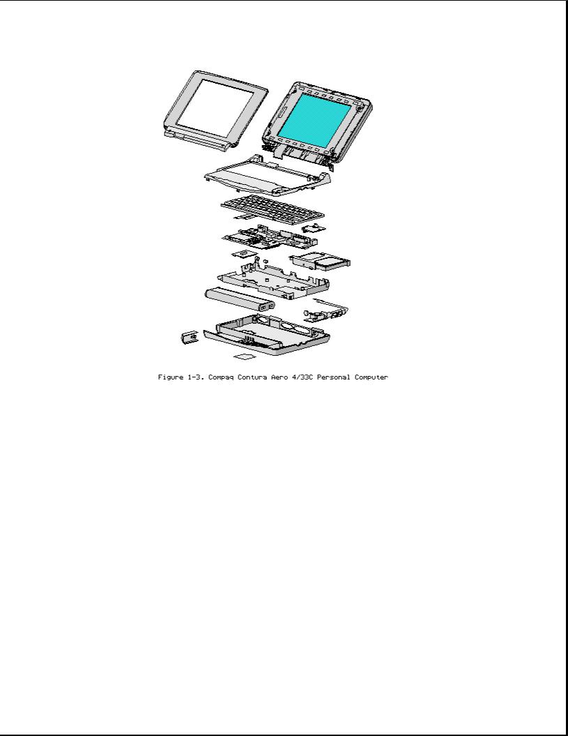
The Compaq Contura Aero Family of Personal Computers joins a display assembly and system unit together with a clutch secured by screws in the chassis, display enclosure, and a display pin allowing it to open and close. The display assembly is secured by screws installed in the front of the display enclosure. The system unit is secured to the system unit enclosure by screwlocks in the rear and screws in the bottom of the system unit enclosure.
SYSTEM UNIT MODULE DESCRIPTION
The system unit (Figure 1-4) includes the following replaceable parts:
o Battery and spacer o Base enclosure
o Keyboard
o Hard drive
o Power supply

o PCMCIA ejector rails o Trackball assembly
o Memory expansion board (optional) o System board
The keyboard is secured to the system unit with four screws and a hook latch in the front. Once the screws are removed, the keyboard must be rotated from the rear forward to disengage it from the hook latch. The keyboard must be removed to allow access to any of the system board components. The keyboard is connected to the system board with two ribbon cables and zero insertion force (ZIF) connectors. The cables do not necessarily have to be disconnected to service the system board. The keyboard may be laid on top of the battery compartment to access the system board.
The |
hard |
drive |
is connected directly |
to the system board |
with no |
||||
intervening cables. It |
is |
mounted |
to |
the |
chassis with a hard drive bracket. |
||||
The |
hard |
drive |
bracket |
is |
secured |
to |
the |
hard drive with |
three screws. |
The power supply is secured to the system board with one threaded standoff. There is no cable between the power supply and the system board; the power supply connects directly to the system board.
The trackball assembly consists of the trackball, buttons, flex cable, and speaker. The trackball plugs directly into the cable with a low insertion force (LIF) connector and mounts with two screws in the right front corner of the base enclosure. The flex cable includes the buttons and speaker. The buttons fit in a recessed area on the right side of the base enclosure and control the functions of the trackball. The speaker is connected to the flex cable with two wires and fits in a narrow area in the right front corner of the base enclosure. Sound is directed through the enclosure. The remainder of the flex cable is routed behind and over the hard drive assembly and plugs with a LIF connector directly into the system board.
The system board is mounted directly to the chassis. All system module components connected to the system board must be removed prior to removing the system board.
The PCMCIA rails are secured to the system board header with two screws at the top. The rails plug directly into the system board connector.
The memory expansion board plugs into the system board in the bottom of the base enclosure. Remove the door, and the memory expansion board plugs into a single connector. System memory can be increased to a maximum 12 MB by adding an 8 MB Memory Expansion Board. A 4 MB Memory Expansion Board is also available.
DISPLAY ASSEMBLY MODULE DESCRIPTION
The display assembly (Figures 1-5 and 1-6) includes the following replaceable parts:
o Display bezel
o Liquid crystal display (LCD) panel o Display inverter board
o Display cable o Display shield
o Display enclosure

Compaq Contura Aero 4/25
The display assembly is secured with two screws in the bottom corners of the display bezel and by a screw in a clutch and a pin to the base enclosure. To remove the display assembly from the base enclosure, the display bezel must be removed first. Then the CPU cover is removed to allow access to the system board.
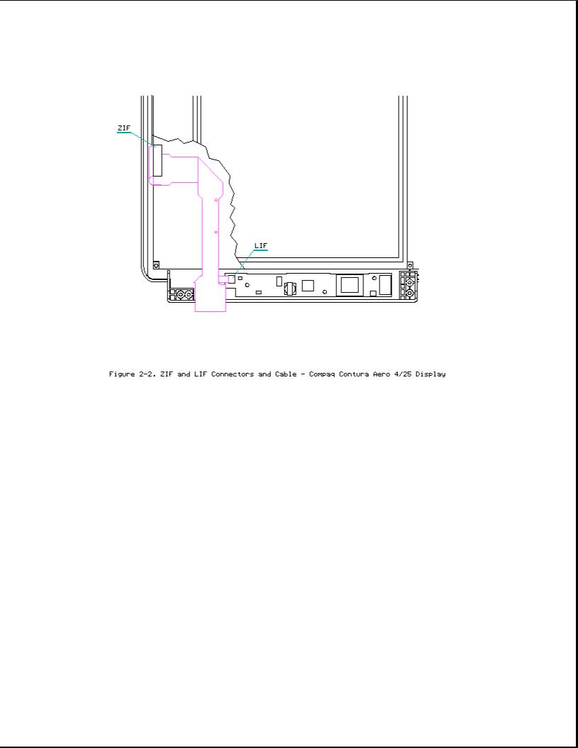
The monochrome LCD is secured to the display enclosure with two screws in the top left corner and one screw in the top right corner. The bottom right corner has two small cables attached to a connector for the backlight and the inverter board.
The display cable is a flex cable plugged into a connector on the left side of the LCD, folded, and secured to the display shield with a pressure sensitive adhesive. One end of the display cable is exposed at the bottom of the display enclosure and is connected to the system board with a zero insertion force (ZIF) slider. The other end is connected with a low insertion force (LIF) connector to the display inverter board.
The display inverter board is aligned in the bottom of the display enclosure with pins. One end connects to the display cable; the other end plugs into the backlight cable of the LCD panel and is held in place with pressure sensitive adhesive tape.
The display shield lays in the display enclosure.
Compaq Contura Aero 4/33C
The display assembly is secured with two screws in the bottom corners of the display bezel and by a screw in a clutch and a pin to the base enclosure. To remove the display assembly from the base enclosure, the display bezel must be removed first. Then the CPU cover is removed to allow access to the system board.
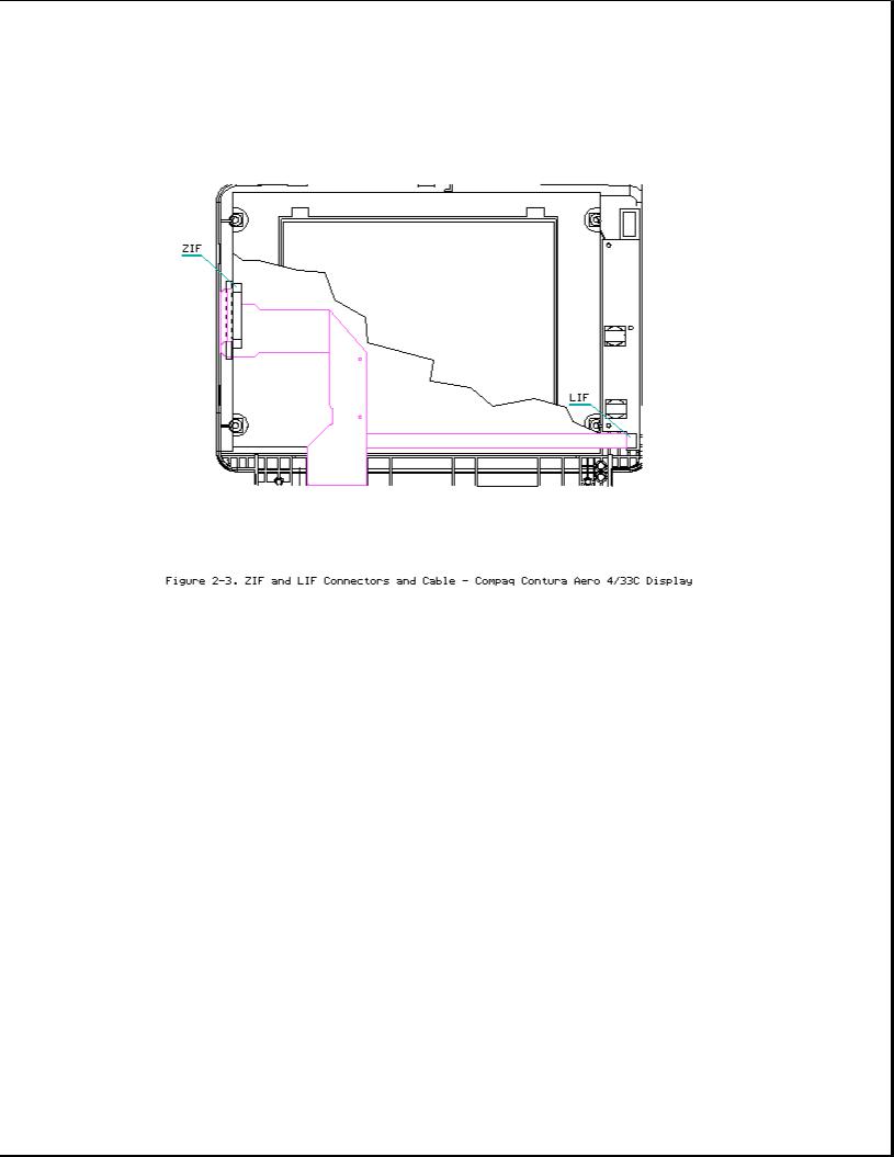
The color LCD is secured to the display enclosure with four screws in the corners of the LCD panel. The top right corner has two small cables attached to a connector for the backlight and the inverter board.
The display cable is a flex cable plugged into a ZIF connector on the left side of the LCD, folded, and secured to the display shield with a pressure sensitive adhesive. One end of the display cable is exposed at the bottom of the display enclosure and is connected to the system board with a ZIF connector. The other end plugs into a LIF connector on the display inverter board in the lower right hand corner of the display enclosure.
The display inverter board is aligned on the right side of the display enclosure and mounted component side down. One end connects to the display cable; the other end plugs into the backlight cable of the LCD panel.
The display shield lays in the display enclosure and has tabs that bend over the screw holes of the LCD and secure the display shield to the LCD.

Chapter 1.2 System Unit Module

Table 1-1. System Unit
===========================================================================
Description Spare Part No. Notes
===========================================================================
1 Base enclosure 197253-001 Includes screw covers.
---------------------------------------------------------------------------
2 System board, 4 MB |
|
Does not |
include PCMCIA ejector |
|
|
|
|
rails. |
|
Compaq |
Contura |
197241-001 |
Includes |
screw covers. |
Aero 4/25 |
|
|
|
|
Compaq |
Contura |
199222-001 |
|
|
Aero 4/33C
---------------------------------------------------------------------------
3 Door assembly |
197239-001 |
Includes battery and memory |
|
|
expansion board doors. |
---------------------------------------------------------------------------
4 Power supply, DC-DC 190521-001 Includes screw covers.
---------------------------------------------------------------------------
5 Hard drive |
|
|
||
- Model 250 |
199233-001 |
Does not include hard drive |
||
- |
Model |
170 |
190661-001 |
bracket. Includes screw covers. |
- |
Model |
84 |
190660-001 |
|
---------------------------------------------------------------------------
6Memory expansion board

- |
4 |
MB |
190565-001 |
- |
8 |
MB |
190596-001 |
---------------------------------------------------------------------------
7 Real time clock |
117099-001 |
battery
---------------------------------------------------------------------------
8 NiMH Battery Pack |
|
|
|
- 8A: Extended Life |
190626-001 |
Extended Life battery does not |
|
- |
8B: Standard |
190697-001 |
include spacer. Standard battery |
- |
8C: Spacer |
197317-001 |
includes spacer. |
---------------------------------------------------------------------------
9 Trackball cable and |
197312-001 |
Includes screw covers. |
speaker assembly |
|
|
---------------------------------------------------------------------------
10 Trackball assembly 197286-001 Includes screw covers.
---------------------------------------------------------------------------
11 Hard drive bracket |
197236-001 |
Includes screws and screw |
|
|
covers. |
---------------------------------------------------------------------------
12 System ROM 197229-001 Includes screw covers.
---------------------------------------------------------------------------
13 CPU cover 197311-001 Includes screw covers.
---------------------------------------------------------------------------
14 CPU chassis 199276-001 Includes clip and screw covers.
===========================================================================
Chapter 1.3 VGA Display

Table 1-2. Compaq Contura Aero 4/25 Monochrome VGA Display
===========================================================================
Description Spare Part No. Notes
===========================================================================
1 Display enclosure |
197237-001 |
Includes enclosure, clutch, pin, |
|
kit |
|
latch, spring, screws, |
display |
|
|
shield, slotted bushing, ground |
|
|
|
clip, screw covers and |
logo. |
---------------------------------------------------------------------------
2 Display panel 190624-001 Includes labels, screw covers.
---------------------------------------------------------------------------
3 Display bezel 197344-001 Includes screw covers.
---------------------------------------------------------------------------
4 Backlight inverter |
190522-001 |
Includes adhesive tape, screw |
board |
|
covers. |
---------------------------------------------------------------------------
5 Display cable |
197238-001 |
Includes ZIF slider and screw |
|
|
covers. |
---------------------------------------------------------------------------
6 Display hardware * |
197316-001 |
Includes screws, ground clip, |
|
|
and screw covers. |
---------------------------------------------------------------------------
* Not Shown
===========================================================================
Table 1-3. Compaq Contura Aero 4/33C Color VGA Display
===========================================================================
Description Spare Part No. Notes
===========================================================================
1 Display enclosure |
199257-001 |
Includes enclosure, clutch, pin, |
|
kit |
|
latch, |
spring, screws, display |
|
|
shield, slotted bushing, screw |
|
|
|
covers |
and logo. |
---------------------------------------------------------------------------
2 Display panel 199232-001 Includes labels, screw covers.
---------------------------------------------------------------------------
3 Display bezel 199260-001 Includes screw covers.
---------------------------------------------------------------------------
4 Backlight inverter 199223-001 Includes screw covers. board
---------------------------------------------------------------------------
5 Display cable |
199258-001 |
Includes ZIF slider and screw |
|
|
covers. |
---------------------------------------------------------------------------
6 Display hardware * |
197316-001 |
Includes screws and screw |
|
|
covers. |
---------------------------------------------------------------------------
* Not Shown
===========================================================================
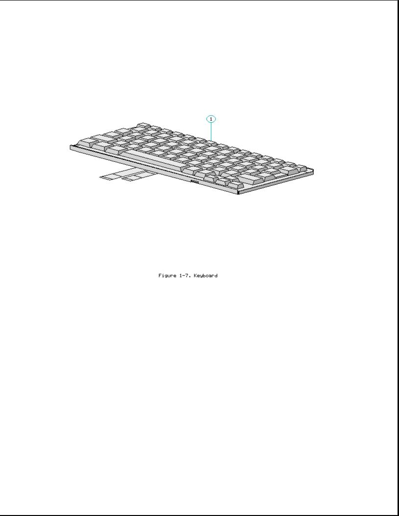
Chapter 1.4 Keyboards
Table 1-4. Notebook Keyboards
===========================================================================
Description Spare Part Number
===========================================================================
1 |
U.S. |
190620-001 |
|
2 |
U.K. |
190620-003 * |
|
3 |
German |
190620-004 * |
|
4 |
French |
190620-005 * |
|
5 |
Italian |
190620-006 * |
|
6 |
Spanish |
190620-007 * |
|
7 |
Danish |
190620-008 * |
|
8 |
Norwegian |
190620-009 * |
|
9 |
Swedish/Finnish |
190620-010 * |
|
10 |
Swiss |
190620-011 * |
|
11 |
French Canadian |
190620-012 * |
|
12 |
Portuguese |
190620-013 * |
|
13 |
Latin American |
190620-016 |
* |
14 |
Belgium |
190620-018 |
* |
15 |
Japanese |
190620-019 |
* |
---------------------------------------------------------------------------
* Not Shown
===========================================================================
Table 1-5. Enhanced Keyboards

===========================================================================
Description Spare Part Number
===========================================================================
1 |
Enhanced II Keyboard U.S. |
112573-001 (No longer |
|
|
available)* |
2 |
Enhanced III Keyboard U.K. |
140536-103 * |
3 |
Enhanced III Keyboard German |
140536-104 * |
4 |
Enhanced III Keyboard French |
140536-105 * |
5 |
Enhanced III Keyboard Italian |
140536-106 * |
6 |
Enhanced III Keyboard Spanish |
140536-107 * |
7 |
Enhanced III Keyboard Danish |
140536-108 * |
8 |
Enhanced III Keyboard Norwegian |
140536-109 * |
9 |
Enhanced III Keyboard Swedish/Finnish |
140536-110 * |
10 |
Enhanced III Keyboard Swiss |
140536-111 * |
11 |
Enhanced III Keyboard French Canadian |
140536-112 * |
12 |
Enhanced III Keyboard Portuguese |
140536-113 * |
13 |
Enhanced III Keyboard Turkish |
140536-114 * |
14 |
Enhanced III Keyboard Greek |
140536-115 * |
15 |
Enhanced III Keyboard Latin American |
140536-116 * |
16 |
Enhanced III Keyboard Arabic |
140536-117 * |
17 |
Enhanced III Keyboard Belgian |
140536-118 * |
18 |
Enhanced III Keyboard Japanese |
140536-119 * |
19 |
Enhanced III Keyboard BHCSY ** |
140536-120 * |
20 |
Enhanced III Keyboard Hungarian |
140536-121 * |
21 |
Enhanced III Keyboard Polish |
140536-122 * |
22 |
Enhanced III Keyboard Slovakian |
140536-123 * |
23 |
Enhanced III Keyboard Russian |
140536-124 * |
24 |
Enhanced III Keyboard Czech |
140536-129 * |
25 |
Enhanced III Keyboard Thai |
140536-130 * |
---------------------------------------------------------------------------
*Not Shown
**Bosnia-Herzegovina, Croatia, Slovenia, and Yugoslavia
===========================================================================
Chapter 1.5 Cables
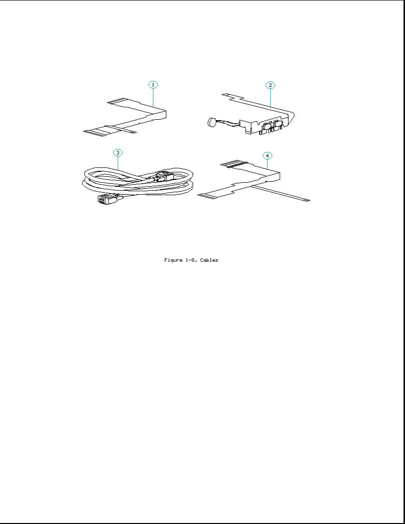
Table 1-6. Cables
===========================================================================
Description Spare Part Number
===========================================================================
1 |
Display |
Cable |
(Compaq Contura Aero 4/25) |
197238-001 |
2 |
Trackball/Speaker Cable |
197312-001 |
||
3 |
Communication |
Cable |
197318-001 |
|
4 |
Display |
Cable |
(Compaq Contura Aero 4/33C) |
199258-001 |
===========================================================================
Chapter 1.6 AC Adapter And Power Cord
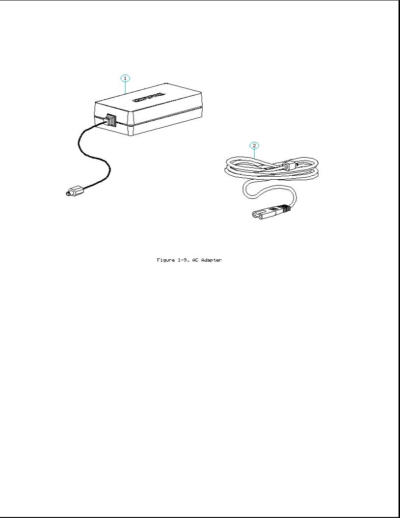
Table 1-7. AC Adapter and Power Cord
===========================================================================
Description Spare Part Number
===========================================================================
1 |
AC Adapter |
|
190621-001 |
|
2 |
Power Cord |
(U.S./Canada) |
197230-001 |
|
3 |
Power Cord |
(U.K.) |
197232-001 * |
|
4 |
Power Cord |
(Europe) |
197231-001 * |
|
5 |
Power Cord |
(Japan) |
197233-001 |
* |
6 |
Power Cord |
(Asia Pacific) |
197234-001 |
* |
---------------------------------------------------------------------------
* Not shown
===========================================================================
Table 1-8. Documentation and Software
===========================================================================
Description Spare Part Number
===========================================================================
MAINTENANCE AND SERVICE GUIDE |
197235-001 |
---------------------------------------------------------------------------
QUICK SETUP CARD, BEYOND SETUP
English |
197243-001 |
German |
197243-041 |
French |
197243-051 |
Italian |
197243-061 |
Spanish |
197243-071 |

---------------------------------------------------------------------------
COMPAQ SERVICE QUICK REFERENCE GUIDE |
106854-001 |
---------------------------------------------------------------------------
LOTUS ORGANIZER MANUAL
English |
137885-001 |
German |
137885-041 |
French |
137885-051 |
Italian |
137885-061 |
Spanish |
137885-071 |
---------------------------------------------------------------------------
Online USER'S GUIDE
English |
190512-001 |
German |
190512-041 |
French |
190512-051 |
Italian |
190512-061 |
Spanish |
190512-071 |
---------------------------------------------------------------------------
WINLINK (diskettes)
English |
197330-001 |
German |
197330-041 |
French |
197330-051 |
Italian |
197330-061 |
Spanish |
197330-071 |
===========================================================================
Table 1-9. Accessories
===========================================================================
Description Spare Part Number
===========================================================================
Automobile adapter |
190551-001 |
|
Memory |
expansion board |
|
4 MB |
|
190565-001 |
8 MB |
|
190596-001 |
Base unit |
190568-001 |
|
PCMCIA |
external diskette drive |
190563-001 |
Mobile |
port expander |
197364-001 |
Carrying case |
121423-001 |
|
Briefcase |
129930-001 |
|
Slipcase cover |
197242-001 |
|
===========================================================================
Table 1-10. Mounting Hardware
===========================================================================
Description Spare Part Number
===========================================================================
Kit, |
CPU base screws and screwlocks |
197315-001 |
Kit, |
display screws |
197316-001 |
Trackball removal tool |
194041-001 |
|
===========================================================================
Table 1-11a. Fastener List for CPU Base Screws and Screwlocks

===========================================================================
Description Type Where Used Part Number Drive Qty
===========================================================================
M2.5 x 7.0 * Hex System board to 139576-004 3/16 2 chassis
---------------------------------------------------------------------------
M2.5 x 3.55 * Hex |
Power supply board to |
197257-001 |
3/16 |
1 |
|
chassis |
|
|
|
---------------------------------------------------------------------------
#4-40 * Hex I/O connector 106902-004 3/16 4
---------------------------------------------------------------------------
M3.0 x 3.0 |
Pan |
Hard |
drive |
bracket to |
139574-001 |
PH/1 |
3 |
|
|
hard |
drive |
|
|
|
|
---------------------------------------------------------------------------
M2.0 x 7.0 |
Pan |
PCMCIA rails to |
144762-002 |
PH/1 |
2 |
|
|
chassis |
|
|
|
---------------------------------------------------------------------------
M2.0 x 2.5 Truss Keyboard to chassis 144863-002 T8/SL 3
---------------------------------------------------------------------------
M2.5 x 12.0 |
Truss Hard drive |
to keyboard 144864-005 |
T8/SL 1 |
|
to chassis |
|
|
---------------------------------------------------------------------------
M2.5 x 6.0 Truss Clutch, system board 144865-003 T8/SL 7
---------------------------------------------------------------------------
M2.5 x 16.0 Truss Base 144865-005 T8/SL 4
---------------------------------------------------------------------------
* Screwlocks
===========================================================================
Table 1-11b. Fastener List for the Compaq Contura Aero 4/25 Display
===========================================================================
Description Type Where Used Part Number Drive Qty
===========================================================================
M2.0 |
x 4.0 |
Truss |
Pin |
144863-001 |
T8/SL |
2 |
|
M2.5 |
x 4.5 |
Truss |
Clutch |
144864-001 |
T8/SL |
2 |
|
M2.0 |
x |
6.0 |
Pan |
Bezel |
197341-002 |
PH/1 |
2 |
M2.0 |
x |
2.5 |
Truss |
Panel to enclosure |
144863-002 |
T8/SL |
3 |
===========================================================================
Table 1-11c. Fastener List for the Compaq Contura Aero 4/33C Display
===========================================================================
Description Type Where Used Part Number Drive Qty
===========================================================================
M2.0 |
x 4.0 |
Truss |
Pin and inverter board |
144863-001 |
T8/SL |
2 |
|
M2.5 |
x 4.5 |
Truss |
Clutch |
144864-001 |
T8/SL |
2 |
|
M2.0 |
x |
6.0 |
Pan |
Bezel |
197341-002 |
PH/1 |
2 |
M3.0 |
x |
6.0 |
Truss |
Panel to enclosure |
198889-001 |
T8/SL |
4 |
===========================================================================
Table 1-12. Miscellaneous Kits
===========================================================================
Description Spare Part Number
===========================================================================
Base unit tilt feet |
197346-001 |

CPU enclosure feet |
197345-001 |
Battery and memory doors |
197239-001 |
PCMCIA eject rails |
197314-001 |
Carton, quantity 5 |
137863-001 |
Carton and buns, quantity 1 |
137864-001 |
Display connector slider |
140071-001 |
Plate logo |
197251-001 |
Battery spacer |
197317-001 |
===========================================================================

Chapter 2. Service Preliminaries
Chapter 2.0 Introduction
This chapter provides general service information for the computer and the base unit.
Adherence to the procedures and precautions described in this chapter is essential for proper service.
Chapter 2.1 Electrostatic Discharge (International)
A sudden discharge of static electricity from a finger or other conductor can destroy static sensitive devices or micro circuitry. Often the spark is neither felt or heard, but damage occurs. An electronic device exposed to electrostatic discharge (ESD) may not be affected at all and will work perfectly throughout a normal cycle. Or it may function normally for a while, then degrade in the internal layers, reducing its life expectancy.
Networks built into many integrated circuits provide some protection, but in many cases, the discharge contains enough power to alter device parameters or melt silicon junctions.
Generating Static
Table 2-1 shows how different activities generate static electricity and at different electrostatic voltage levels.
Table 2-1. Typical Electrostatic Voltages
===========================================================================
|
|
Relative Humidity |
|
Event |
10% |
40% |
55% |
===========================================================================
Walking across carpet |
|
35,000V |
15,000V |
7,500V |
Walking across vinyl |
floor |
12,000V |
5,000V |
3,000V |
Motions of bench worker |
6,000V |
800V |
400V |
|
Removing DIPS from plastic tubes |
2,000V |
700V |
400V |
|
Removing DIPS from vinyl trays |
11,500V |
4,000V |
2,000V |
|
Removing DIPS from styrofoam |
14,500V |
5,000V |
3,500V |
|
Removing bubble pack |
from PCBs |
26,000V |
20,000V |
7,000V |
Packing PCBs in foam |
lined box |
21,000V |
11,000V |
5,000V |
---------------------------------------------------------------------------
NOTE: 700 volts can degrade a product.
===========================================================================
Preventing Electrostatic Damage To Equipment
Many electronic components are sensitive to ESD. Circuitry design and

structure determine the degree of sensitivity. The following proper packaging and grounding precautions are necessary to prevent damage:
o Protect all electrostatic parts and assemblies with conductive or approved containers or packaging.
o Keep electrostatic sensitive parts in their containers until they arrive at static free stations.
o Place items on a grounded surface before removing them from their container.
o Always be properly grounded when touching a sensitive component or assembly.
o Place reusable electronic sensitive parts from assemblies in protective packaging or conductive foam.
Use transporters and conveyors made of antistatic belts and metal roller bushings. Mechanized equipment used for moving materials must be wired to ground and proper materials selected to avoid static charging. When grounding is not possible, use an ionizer to dissipate electric charges.
Preventing Damage to Drives
To prevent static damage to hard drives, use the following precautions:
o Handle drives gently, using static guarding techniques.
o Store drives in the original shipping containers.
o Avoid dropping drives from any height onto any surface.
o Handle drives on surfaces that have at least one inch of shock proof foam.
o Always place drives PCB assembly side down on the foam.
Grounding Methods
The method for grounding must include a wrist strap or a foot strap at a grounded workstation. When seated, wear a wrist strap connected to a grounded system. When standing, use footstraps and a grounded floor mat.
Table 2-2. Static Shielding Protection Levels
===========================================================================
Method Voltages
===========================================================================
Antistatic |
Plastic |
1,500 |
Carbon Loaded Plastic |
7,500 |
|
Metallized |
Laminate |
15,000 |
===========================================================================
Grounding Workstations
To prevent static damage at the workstation, use the following precautions:
o Cover the workstation with approved static dissipative material. Provide a wrist strap connected to the work surface and properly grounded tools and equipment.
o Use static dissipative mats, heel straps, or air ionizers to give added protection.
o Handle electrostatic sensitive components, parts, and assemblies by the case or PCB laminate. Handle them only at static free workstations.
o Avoid contact with pins, leads, or circuitry.
o Turn off power and input signals before inserting and removing connectors or test equipment.
o Use fixtures made of static safe materials when fixtures must directly contact dissipative surfaces.
o Keep work area free of nonconductive materials such as ordinary plastic assembly aids and Styrofoam.
o Use field service tools, such as cutters, screwdrivers, vacuums, that are conductive.
o Use a portable field service kit with a static dissipative vinyl pouch that folds out of a work mat. Also use a wrist strap and a ground cord for the work surface. Ground the cord to the chassis of the equipment undergoing test or repair.
Grounding Equipment
Use the following equipment to prevent static electricity damage to the equipment:
Wrist Straps are flexible straps with a minimum of 1 megohm +/- 10% resistance to the ground cords. To provide proper ground, a strap must be worn snug against the skin. On grounded mats without banana plug connectors, connect a wrist strap with alligator clips.
Heelstraps/Toestraps/Bootstraps can be used at standing workstations and are compatible with most types of boots and shoes. On conductive floors or dissipative floor mats, use them on both feet with a minimum of 1 megohm resistance between operator and ground. To be effective, the conductive strips must be worn in contact with the skin.
Recommended Materials and Equipment
Other materials and equipment that are recommended for use in preventing static electricity include:
o Antistatic tape
o Antistatic smocks, aprons, or sleeve protectors

o Conductive bins, and other assembly or soldering aids
o Conductive foam
o Conductive table top workstations with ground cord of 1 megohm of resistance
o Static dissipative table or floor mats with hard tie to ground
o Field service kits
o Static awareness labels
o Wrist straps and footwear straps providing 1 megohm +/- 10% resistance
o Material handling packages
o Conductive plastic bags
o Conductive plastic tubes
o Conductive tote boxes
o Metal tote boxes
o Opaque shielding bags
o Transparent metallized shielding bags
o Transparent shielding tubes
SERVICE CONSIDERATIONS
Listed below are some of the considerations that should be kept in mind during the disassembly and assembly of the computer.
Tool Requirements:
o Flat bladed screwdriver
o Torx T8 screwdriver (included in 130619-001)
o Hex socket driver (3/16)
o 25 Pin printer loopback plug (included in 100767-001)
o 9 Pin serial loopback plug (included in 100767-001)
o Cross recess (Phillips) screwdriver (included in 130619-001)
o Trackball tool (spare part number 194041-001)
o Case utility tool (spare part number 119070-001 and included in 10076-001)
o PCMCIA external diskette drive (part number 190533-001)
o Preloaded application diskettes

Screws
The screws used in these products are not interchangeable. If an incorrect screw is used during the reassembly process, it could cause damage to the unit. Compaq strongly recommends that all screws removed during the disassembly process be kept with the part that was removed, then returned to their proper locations.
IMPORTANT: As each subassembly is removed from the computer, it should be placed away from the work area to prevent damage.
Cables and Connectors
Most cables used throughout the unit are flex cables (Figures 2-1, 2-2, 2-3). These cables must be handled with extreme care to avoid damage. Apply only the tension required to seat or unseat the cables during insertion or removal from the connector. Handle cables by the connector or pull tabs whenever possible. In all cases, avoid bending, twisting, or tearing the cables, and ensure that cables are placed in such a way that they cannot be caught or snagged by parts being removed or replaced.
>>>>>>>>>>>>>>>>>>>>>>>>>>>>>>>>> CAUTION <<<<<<<<<<<<<<<<<<<<<<<<<<<<<<<<<
When servicing these units, ensure that cables are placed in their proper location during the reassembly process. Improper cable placement can cause severe damage to the unit.
>>>>>>>>>>>>>>>>>>>>>>>>>>>>>>>>>>>>><<<<<<<<<<<<<<<<<<<<<<<<<<<<<<<<<<<<<<

Plastics
The plastics used can be damaged by application of excessive force during disassembly and reassembly. When handling the plastic cases and housing assemblies, use care. Do not use screwdrivers or similar tools to pry apart plastics. Where necessary, use the Case utility tool (spare part number 119070-001). Proper handling of this tool is illustrated in the disassembly and reassembly procedures.
Disposal of a Used Battery
Battery components are considered environmentally harmful. Disposal of a Nickel Metal Hydride (NiMH) Battery Pack should comply with country, state, province, or local regulations. Whenever possible, battery components should be recycled.
>>>>>>>>>>>>>>>>>>>>>>>>>>>>>>>>> CAUTION <<<<<<<<<<<<<<<<<<<<<<<<<<<<<<<<<
Never attempt to open or service a battery pack. Opening a battery pack not only damages the pack and makes it unusable, but also exposes potentially harmful battery components.
>>>>>>>>>>>>>>>>>>>>>>>>>>>>>>>>>>>>><<<<<<<<<<<<<<<<<<<<<<<<<<<<<<<<<<<<<<
Chapter 2.1 Electrostatic Discharge (U.S. and Canada)

A sudden discharge of static electricity from a finger or other conductor can destroy static sensitive devices or micro circuitry. Often the spark is neither felt or heard, but damage occurs. An electronic device exposed to electrostatic discharge (ESD) may not be affected at all and will work perfectly throughout a normal cycle. Or it may function normally for a while, then degrade in the internal layers, reducing its life expectancy.
Networks built into many integrated circuits provide some protection, but in many cases, the discharge contains enough power to alter device parameters or melt silicon junctions.
Generating Static
Table 2-1 shows how different activities generate static electricity and at different electrostatic voltage levels.
Table 2-1. Typical Electrostatic Voltages
===========================================================================
|
|
Relative Humidity |
|
Event |
10% |
40% |
55% |
===========================================================================
Walking across carpet |
|
35,000V |
15,000V |
7,500V |
Walking across vinyl |
floor |
12,000V |
5,000V |
3,000V |
Motions of bench worker |
6,000V |
800V |
400V |
|
Removing DIPS from plastic tubes |
2,000V |
700V |
400V |
|
Removing DIPS from vinyl trays |
11,500V |
4,000V |
2,000V |
|
Removing DIPS from styrofoam |
14,500V |
5,000V |
3,500V |
|
Removing bubble pack |
from PCBs |
26,000V |
20,000V |
7,000V |
Packing PCBs in foam |
lined box |
21,000V |
11,000V |
5,000V |
---------------------------------------------------------------------------
NOTE: 700 volts can degrade a product.
===========================================================================
Preventing Electrostatic Damage To Equipment
Many electronic components are sensitive to ESD. Circuitry design and structure determine the degree of sensitivity. The following proper packaging and grounding precautions are necessary to prevent damage:
o Protect all electrostatic parts and assemblies with conductive or approved containers or packaging.
o Keep electrostatic sensitive parts in their containers until they arrive at static free stations.
o Place items on a grounded surface before removing them from their container.
o Always be properly grounded when touching a sensitive component or assembly.

o Place reusable electronic sensitive parts from assemblies in protective packaging or conductive foam.
Use transporters and conveyors made of antistatic belts and metal roller bushings. Mechanized equipment used for moving materials must be wired to ground and proper materials selected to avoid static charging. When grounding is not possible, use an ionizer to dissipate electric charges.
Preventing Damage to Drives
To prevent static damage to hard drives, use the following precautions:
o Handle drives gently, using static guarding techniques.
o Store drives in the original shipping containers.
o Avoid dropping drives from any height onto any surface.
o Handle drives on surfaces that have at least one inch of shock proof foam.
o Always place drives PCB assembly side down on the foam.
Grounding Methods
The method for grounding must include a wrist strap or a foot strap at a grounded workstation. When seated, wear a wrist strap connected to a grounded system. When standing, use footstraps and a grounded floor mat.
Table 2-2. Static Shielding Protection Levels
===========================================================================
Method Voltages
===========================================================================
Antistatic |
Plastic |
1,500 |
Carbon Loaded Plastic |
7,500 |
|
Metallized |
Laminate |
15,000 |
===========================================================================
Grounding Workstations
To prevent static damage at the workstation, use the following precautions:
o Cover the workstation with approved static dissipative material. Provide a wrist strap connected to the work surface and properly grounded tools and equipment.
o Use static dissipative mats, heel straps, or air ionizers to give added protection.
o Handle electrostatic sensitive components, parts, and assemblies by the case or PCB laminate. Handle them only at static free workstations.
o Avoid contact with pins, leads, or circuitry.

o Turn off power and input signals before inserting and removing connectors or test equipment.
o Use fixtures made of static safe materials when fixtures must directly contact dissipative surfaces.
o Keep work area free of nonconductive materials such as ordinary plastic assembly aids and Styrofoam.
o Use field service tools, such as cutters, screwdrivers, vacuums, that are conductive.
o Use a portable field service kit with a static dissipative vinyl pouch that folds out of a work mat. Also use a wrist strap and a ground cord for the work surface. Ground the cord to the chassis of the equipment undergoing test or repair.
Grounding Equipment
Use the following equipment to prevent static electricity damage to the equipment:
Wrist Straps are flexible straps with a minimum of 1 megohm +/- 10% resistance to the ground cords. To provide proper ground, a strap must be worn snug against the skin. On grounded mats without banana plug connectors, connect a wrist strap with alligator clips.
Heelstraps/Toestraps/Bootstraps can be used at standing workstations and are compatible with most types of boots and shoes. On conductive floors or dissipative floor mats, use them on both feet with a minimum of 1 megohm resistance between operator and ground. To be effective, the conductive strips must be worn in contact with the skin.
Recommended Materials and Equipment
Other materials and equipment that are recommended for use in preventing static electricity include:
o Antistatic tape
o Antistatic smocks, aprons, or sleeve protectors
o Conductive bins, and other assembly or soldering aids
o Conductive foam
o Conductive table top workstations with ground cord of 1 megohm of resistance
o Static dissipative table or floor mats with hard tie to ground
o Field service kits
o Static awareness labels
o Wrist straps and footwear straps providing 1 megohm +/- 10% resistance

o Material handling packages
o Conductive plastic bags
o Conductive plastic tubes
o Conductive tote boxes
o Metal tote boxes
o Opaque shielding bags
o Transparent metallized shielding bags
o Transparent shielding tubes
SERVICE CONSIDERATIONS
Listed below are some of the considerations that should be kept in mind during the disassembly and assembly of the computer.
Tool Requirements:
o Flat bladed screwdriver
o Torx T8 screwdriver (included in 130619-001)
o Hex socket driver (3/16)
o 25 Pin printer loopback plug (included in 100767-001)
o 9 Pin serial loopback plug (included in 100767-001)
o Cross recess (Phillips) screwdriver (included in 130619-001)
o Trackball tool (spare part number 194041-001)
o Case utility tool (spare part number 119070-001 and included in 10076-001)
o PCMCIA external diskette drive (part number 190533-001)
o Preloaded application diskettes (Compaq Order Center, 1-800-952-7689)
Screws
The screws used in these products are not interchangeable. If an incorrect screw is used during the reassembly process, it could cause damage to the unit. Compaq strongly recommends that all screws removed during the disassembly process be kept with the part that was removed, then returned to their proper locations.
IMPORTANT: As each subassembly is removed from the computer, it should be placed away from the work area to prevent damage.
Loading...