


Operating Instructions
GB
English, 1
OSX 896LD CX OSX 896D CK OSX 896D CX
OVEN
Contents
GB
Installation, 2-3
Positioning Electrical connection Data plate
Description of the appliance, 4
Overall view
Control panel
Oven structure, 5
Start-up and use, 6-7
Control panel/door lock
Setting the clock
Setting the minute minder
Concealed handle
Restoring the factory settings
Standby
Cooking modes, 8-15
ExtraLarge Space The divider
Small Space
Main Space
Using the Small Space and Main Space at the same time
Programming cooking Practical cooking advice
Cooking advice table for ovens with an ExtraLarge Space cavity
Cooking advice table for the Main Space feature Cooking advice table for the Small Space feature Cooking advice table for using the Small Space and Main Space at the same time
Precautions and tips, 16
General safety Disposal
Respecting and conserving the environment
Care and maintenance, 17
Switching the appliance off Cleaning the appliance Cleaning the oven door Replacing the light bulb
Troubleshooting, 18
After Sales Service, 19
Guarantee, 20
|
us |
on |
|
|
24 |
||
phone 24 |
|||
your |
|||
|
24 |
|
|
Please08448activate |
|||
to |
guarantee |
||

Installation
! Before placing your new appliance into operation GB please read these operating instructions carefully. If
the appliance is sold, given away or moved, please make sure the booklet is also passed on to the new owners so that they may benefit from the advice contained within it.
! Please keep these operating instructions for future reference. it contains important information on installation, operation and safety.
Positioning
!Keep packaging material out of the reach of children. It can become a choking or suffocation hazard. (see Precautions and tips).
!The appliance must be installed by a qualified person in compliance with the instructions provided. Incorrect installation may damage property or cause harm to people or animals.
Built-in appliances
Use the appropriate cabinet to ensure that the appliance functions properly.
•The panels adjacent to the oven must be made of heat-resistant material.
•Cabinets with a veneer exterior must be assembled with glues which can withstand temperatures of up to 100°C.
•To install the oven under the counter (see diagram) or in a kitchen unit, the cabinet must have the following dimensions:
<![endif]>590 mm.


 20 mm.
<![endif]>570 mm.


|
. |
|
|
mm |
|
550 . |
|
|
min |
|
|
|
|
. |
45 |
mm |
|
|
|
|
|
560 |
mm. |
|
|
|
<![endif]>575-585 mm.
595 |
mm. |
|
|
. |
|
550 |
mm |
||
|
. |
|||
|
|
|
|
|
|
|
|
mm |
|
|
|
20,5 |
|
.* |
|
|
|
mm |
|
|
|
22,5 |
|
|
* Stainless steel models only
! The appliance must not come into contact with electrical parts once it has been installed.
The indications for consumption given on the data plate have been calculated for this type of installation.
Ventilation |
. |
45 |
mm |
. |
mm |
|
||
560 |
|
|
|
To ensure good ventilation, the back panel of the cabinet must be removed. It is advisable to install the oven so that it rests on two strips of wood, or on a completely flat surface with an opening of at least 45 x 560 mm (see figures).
min. 20 mm |
FAN ASSISTED |
MODE |
min. 45 mm |
Centring and fixing
Secure the appliance to the cabinet:
•Open the oven door.
•Remove the 2 rubber plugs covering the fixing holes on the perimeter frame.
•Fix the oven to the cabinet using the 2 wood screws.
•Replace the rubber plugs.
! All parts which ensure the safe operation of the appliance must not be removable without the aid of a tool.
PLEASE PHONE US TO REGISTER YOUR APPLIANCE AND ACTIVATE YOUR PARTS GUARANTEE ON 08448 24 24 24
2
Electrical connection
The electrical connection to the mains must be made on the appliance. The power voltage and frequency are as indicated on the rating plate.
! THIS APPLIANCE MUST BE EARTHED.
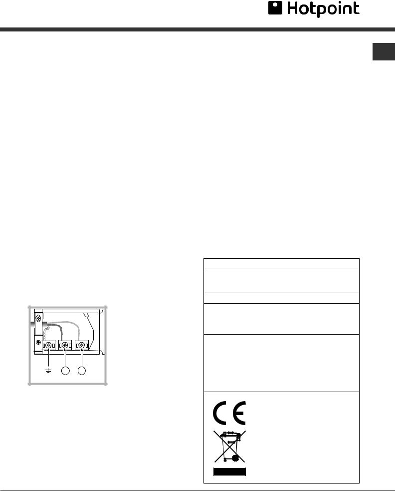
Connecting the power supply cable
To open the terminal board:
•Using a screwdriver, press on the tabs situated on each side of the terminal board cover.
•Pull open the terminal board cover.
To connect the power supply cable, proceed as follows:
•Unscrew the cable clamp screw and the contact screws L-N-6.
•Fasten the wires beneath the screwheads using the following colour scheme: Blue (N) Brown (L)
Yellow-Green 6
•Fasten the power supply cable in the corresponding cable clamp and close the cover.
Electrical Connection:
Voltage Frequency: 230 V-1+N 50Hz
Fuse Section: 16A Supply cable: 3x1.5mm2
4 2
NL
You can connect your oven to the system means of a terminal board. Refer to above information for the minimal cable sections and the calibration of the protective elements according to the connection.
If the appliance is installed with a junction box, an omnipolar circuit breaker - with a minimum contact opening of 3mm - should be installed between the appliance and the mains.
Power cable supply connection to the electrical
mains: |
GB |
|
We recommend you use a power supply cable which is long enough to allow you to take the oven out of its recess in the event of maintenance operations (only use HAR - H 05 - RRF quality cables fitted with a plug conforming to the regulations in force.
The plug must be accessible at all times.
Unplug the appliance before all operations, even when replacing the oven lamp.
Using the appliance without correct earthing is highly dangerous.
! After connecting the appliance to the flexible cable, tighten all the screws on the terminal board.
APPLIANCE SPECIFICATIONS
|
width 43.4 cm |
|
height 39.5 cm |
|
depth 40.8 cm |
Volume |
70 l |
Electrical |
voltage: 230 - 240 V~ 50/60 Hz |
maximum power absorbed |
|
connections |
2600-2800 W (see data plate) |
|
Directive 2002/40/EC on the label |
|
of electric ovens. |
ENERGY |
Standard EN 50304 |
|
|
LABEL |
Declared energy consumption for |
|
Forced convection Class – |
|
heating mode: ECO |
|
This appliance conforms to the |
|
following European Economic |
|
Community directives: |
|
2006/95/EEC dated 12/12/06 (Low |
|
Voltage) and subsequent amendments |
|
– 2004/108/EEC dated 15/12/04 and |
|
subsequent amendments |
|
- 93/68/EEC dated 22/07/93 and |
|
subsequent amendments |
|
- 2002/96/EC and subsequent |
|
amendments. |
|
1275/2008 Standby/off mode |
PLEASE PHONE US TO REGISTER YOUR APPLIANCE AND ACTIVATE YOUR PARTS GUARANTEE ON 08448 24 24 24
3
Description of the appliance
Overall view
GB
Control panel |
GUIDE RAILS |
|
for the sliding racks |
||
|
position 7 |
|
DIVIDER shelf |
position 6 |
|
RACK shelf |
Divider "D" position |
|
position 5 |
||
|
||
|
position 4 |
|
DRIPPING PAN shelf |
position 3 |
|
position 2 |
||
|
||
|
position 1 |
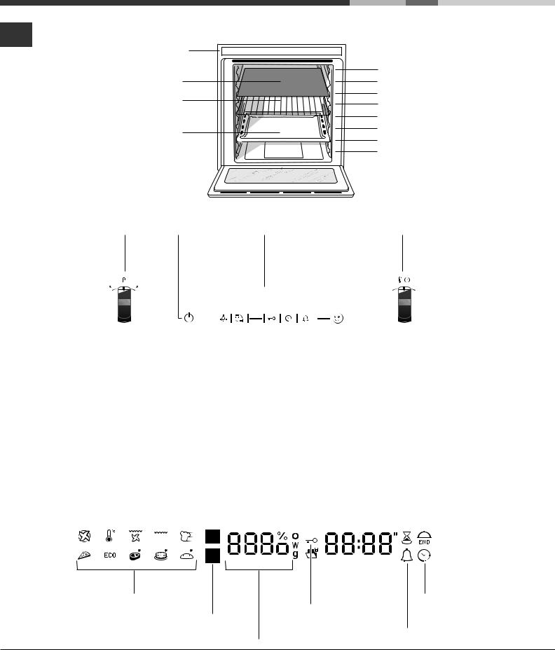
Control panel
SELECTOR |
CONTROL PANEL DISPLAY |
THERMOSTAT / TIMER |
knob |
POWER BUTTON |
knob |
|
|
|
|
|
|
|
|
|
|
|
|
|
|
|
|
|
|
|
|
|
|
|
|
|
|
|
|
|
|
|
|
|
|
|
|
|
|
|
|
|
|
|
|
|
|
|
|
|
LIGHT |
|
|
|
|
|
|
|
START / |
||
|
icon |
|
|
|
|
|
|
|
STOP |
||
|
|
|
|||||||||
|
SELECT |
|
|
|
MINUTE MINDER |
||||||
|
CAVITY |
|
|
|
icon |
||||||
|
icon |
|
|
TIMER |
|||||||
|
|
|
|
CONTROL |
|
||||||
|
PANEL LOCKED icon |
|
icon |
||||||||
|
|
|
|
|
|
|
|
|
|
|
|
Display
|
|
|
|
|
|
|
|
|
|
|
|
|
CAVITY TEMPERATURE |
|
|
|
|
|
|||||||
|
|
|
|
|
|
|
|
|
|
|
|
|
display |
|
|
|
|
|
|||||||
|
|
|
SMALL CAVITY |
|
|
|
|
|
|
|
|
|
|
TIME |
|
DURATION |
|
END OF COOKING |
|||||||
|
|
|
|
|
|||||||||||||||||||||
|
|
|
|
|
|
|
|
|
|
|
|
||||||||||||||
|
|
|
|
icon |
|
|
|
|
|
|
|
|
|
|
display |
|
icon |
|
icon |
||||||
|
|
|
|
|
|
|
|
|
|
|
|
|
|
|
|
|
|
|
|
|
|
|
|
|
|
|
|
|
|
|
|
|
|
|
|
|
|
|
|
|
|
|
|
|
|
|
|
|
|
|
|
|
|
|
|
|
|
|
|
|
|
|
|
|
|
|
|
|
|
|
|
|
|
|
|
|
|
|
|
|
|
|
|
|
|
|
|
|
|
|
|
|
|
|
|
|
|
|
|
|
|
|
|
|
|
|
|
|
|
|
|
|
|
|
|
|
|
|
|
|
|
|
|
|
|
|
|
|
|
|
|
|
|
|
|
|
|
|
|
|
|
|
|
|
|
|
|
|
|
|
|
|
|
|
|
|
|
|
|
|
|
|
|
|
|
|
|
|
|
|
|
|
|
|
|
|
|
|
|
|
|
|
|
|
|
|
|
|
|
|
|
|
|
|
|
|
|
|
|
|
|
|
|
|
|
|
|
MODE |
|
CONTROL |
CLOCK |
icons |
MAIN CAVITY |
PANEL LOCK |
icon |
|
icon |
indicator |
|
|
|
CAVITY PREHEATING / |
MINUTE MINDER |
|
|
RESIDUAL HEAT |
icon |
|
|
indicator |
|
PLEASE PHONE US TO REGISTER YOUR APPLIANCE AND ACTIVATE YOUR PARTS GUARANTEE ON 08448 24 24 24
4

Oven structure
The OPEN SPACE oven has a capacity of 70 litres and offers users the option of cooking on 4 shelves at the same time or cooking large quantities which would not necessarily be possible in a traditional oven.
The 56 universal (Creation) and automatic (Success) cooking modes guarantee perfect results every time, regardless of the dish you are cooking.
OPEN SPACE also offers maximum comfort for all requirements, with 4 different operating options: the oven is one large compartment but can be divided into separate spaces of various sizes, each with its own independent temperature and duration controls.
This is made possible thanks to the heat-insulating
ExtraLarge Space: cooking on 4 shelf levels
|
RACK |
|
EXTRALARGE |
RACK |
|
RACK |
||
SPACE |
 DRIPPING PAN
DIVIDER, which divides the whole ExtraLarge Space
into two different-sized spaces: the Main Space and GB the Small Space.
The two Main and Small Space compartments may be used at the same time to cook different dishes more quickly, or they may be used separately so that only the space necessary is used.
When the two compartments are used at the same time, the cooking temperature of each may be adjusted to a value between 30° and 300°. There may be a difference in temperature of 100° between the two zones, which means it is possible to cook very different dishes without any flavours or aromas intermingling.
|
Main and Small Space: simultaneous operation |
SMALL |
RACK or DRIPPING PAN |
SPACE |
Divider "D" (fixed position) |
|
RACK (cooking on 3 shelves) |
MAIN |
RACK (cooking on 3 shelves) |
SPACE |
DRIPPING PAN |
|
(cooking on 3 shelves) |
|
Cooking using the Small Space only |
SMALL |
RACK or DRIPPING PAN |
SPACE |
Divider "D" |
MAIN |
(fixed position) |
|
|
SPACE |
|
Cooking using the Main Space only: cooking on 3 shelf levels
SMALL |
|
SPACE |
Divider "D" (fixed position) |
|
RACK (cooking on 3 shelves) |
MAIN |
RACK (cooking on 3 shelves) |
SPACE |
DRIPPING PAN |
|
(cooking on 3 shelves) |
The table below lists the possible temperature |
guide you through the correct procedure used to |
||
values which may be set. The intelligent display will |
adjust the temperature of the two cavities. |
||
|
|
|
|
Temperature in the first cavity |
|
|
Temperature in the second cavity |
(Main or Small Space) |
|
|
(Small or Main Space) |
From 40°C to 150°C |
|
The temperature difference in relation to the first cavity selected is no greater than 100°C |
|
|
|
|
|
|
For example: if you set one cavity to 90°C, |
||
|
|||
you may set a value of between 40°C (90°C-50°C) and 140°C (90°C+50°C) for the other. |
|||
From 155°C to 200°C |
|
The temperature difference in relation to the first cavity selected is no greater than 70°C |
|
|
|
|
|
|
For example: if you set one cavity to 180°C, |
||
you may set a value of between 110°C (180°C-70°C) and 250°C (180°C+70°C) for the other. |
|||
From 205°C to 250°C |
|
The temperature difference in relation to the first cavity selected is no greater than 100°C |
|
|
|
|
|
|
For example: if you set one cavity to 210°C, |
||
|
|||
you may set a value of between 110°C (210°C-100°C) and 250°C (max.temperature setting) for the other. |
|||
|
|
|
|
PLEASE PHONE US TO REGISTER YOUR APPLIANCE AND ACTIVATE YOUR PARTS GUARANTEE ON 08448 24 24 24
5

Start-up and use
!The first time you use your appliance, heat the GB empty oven with its door closed at its maximum temperature for at least half and hour. Make sure
that the room is well ventilated before switching the oven off and opening the oven door. The appliance may emit a slightly unpleasant odour caused by protective substances used during the manufacturing process burning away.
!To make the setting process easier, press and hold the + and – buttons to scroll through the numbers on the display rapidly.
!Each setting will automatically be stored in the appliance memory after 10 seconds.
!During operation, we recommend the removal of any crockery or delicate foodstuffs from the cavities not being used.
Some models are equipped with a system of hinges which allows the door to close slowly, without the user having to follow the movement through with his/ her hand. To use the system correctly, before closing the door:
•Open the door fully.
•Do not force the closing movement manually.
! Once cooking has begun, before the DIVIDER is removed, the oven must be switched off using the
 button.
!Every time the oven is switched on it is set to the CREATION cooking mode.
!The touch controls cannot be activated if the user is wearing gloves.
Control panel/door lock
! The control panel can be locked while the oven is off, once cooking has started or finished and during programming.
To lock the oven controls, press and hold the  button for at least 2 seconds. A buzzer will sound and the TEMPERATURE display shows the key symbol “O—n”. The
  icon will light up to indicate lock activation.
To deactivate the lock, press and hold the  button again for at least 2 seconds.
Setting the clock
! The clock can only be set when the oven is switched off. If the oven is in standby mode,
pressing the  button once will display the current time setting. Press it again to set the time.
After connection to the power supply network or after
a blackout, the  button and the digits on the display will flash for 10 seconds.
To set the clock:
1.Press button  .
.
2.Turn the TIMER knob towards “+” and “-” to adjust the hour value.
3.Once you have reached the correct hour value,
press the  button.
4. Repeat the above process to set the minutes.
If a blackout occurs, it will be necessary to reset the
clock. If the  icon flashes on the display, this indicates that the clock has not been set correctly.
Setting the minute minder
! The minute minder may be set regardless of whether the oven is switched on or off. It does not switch the oven on or off.
When the set time has elapsed, the minute minder emits a buzzer that will automatically stop after 30 seconds or when any active button on the control panel is pressed.
To adjust the minute minder, proceed as follows:
1.Press button  .
.
2.Adjust the time as desired by turning the TIMER knob towards “+” and “-”.
3.Once you have reached the desired value, press
the  button again.
The lit  symbol will remind you that the minute minder is on. The DISPLAY will show the countdown.
To cancel the minute minder, press the  button and use the knob to set the time to 00:00. Press
button  again.
The  icon will switch off to indicate that the minute minder has been disabled.
PLEASE PHONE US TO REGISTER YOUR APPLIANCE AND ACTIVATE YOUR PARTS GUARANTEE ON 08448 24 24 24
6
 Loading...