


Operating Instructions
OVEN
GB
English,1
OS 89 /HP
OS 89 IX/HP
OS 89 C /HP
OS 89 C IX/HP
Contents
GB
Installation, 2-3
Positioning
Electrical connection
Technical data
Description of the appliance, 4
Overall view
Control panel
Display
Start-up and use, 5-9
Oven structure
Setting the clock
Setting the timer
Starting the oven
Programming cooking
Practical cooking advice
Cooking advice table
Precautions and tips, 10
General safety
Disposal
Respecting and conserving the environment
Care and maintenance, 11
Switching the appliance off
Cleaning the appliance
Cleaning the oven door
Replacing the light bulb
Assembling the sliding rack kit
After Sales Service, 15
Guarantee, 16
Installation
560 m
m
.
45 mm.
GB
Before operating your new appliance please read
this instruction booklet carefully. It contains
important information concerning the safe operation,
installation and maintenance of the appliance.
Please keep these operating instructions for future
reference. Pass them on to any new owners of the
appliance.
Positioning
Keep all packaging material out of reach of
children. It may present a choking or suffocation
hazard (see Precautions and tips).
The appliance must be installed by a qualified
professional in accordance with the instructions
provided. Incorrect installation may cause harm to
people and animals or may damage property.
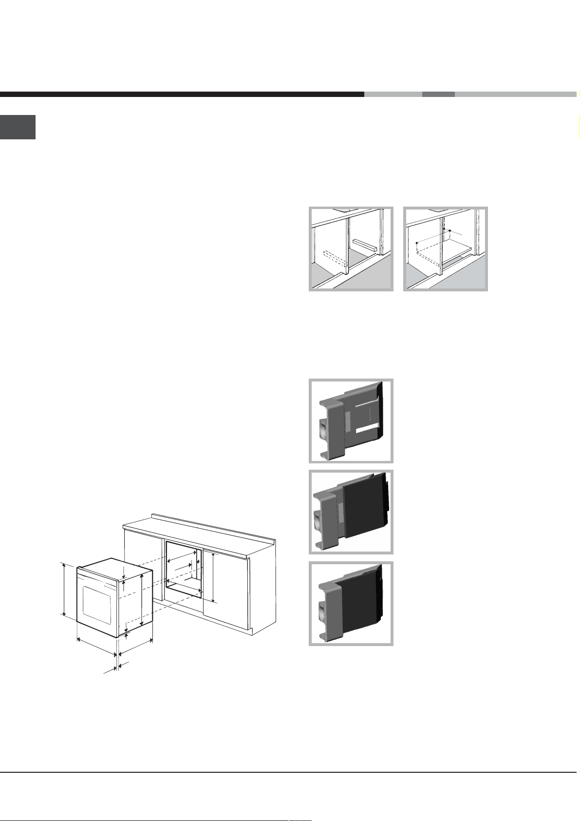
Built-in appliance
Use a suitable cabinet to ensure that the appliance
functions properly.
The panels adjacent to the oven must be made of
heat-resistant material.
Cabinets with a veneer exterior must be
assembled with glues which can withstand
temperatures of up to 100°C.
To install the oven under the counter (see
diagram) or in a kitchen unit, the cabinet must
have the following dimensions:
Ventilation
To ensure adequate ventilation is provided, the back
panel of the cabinet must be removed. It is
advisable to install the oven so that it rests on two
strips of wood, or on a completely flat surface with
an opening of at least 45 x 560 mm (see diagrams).
Centring and fixing
Position the 4 tabs on the side of the oven so that
they are aligned with the 4 holes on the outer frame.
Adjust the tabs in accordance with the thickness of
the cabinet side panel, as shown below:
20 mm thick: take off the
removable part of the tab (see
diagram).
18 mm thick: use the first
groove, which has already
been set in the factory (see
diagram).
.
in
. m
m
m
7
4
5
23 mm.
595 mm.
5 mm.
595 mm.
545 mm.
24 mm.
45 mm.
558 mm.
576 mm.
The appliance must not come into contact with
electrical parts once it has been installed.
The indications for consumption given on the data
plate have been calculated for this type of
installation.
2
593 mm.
16 mm thick: use the second
groove (see diagram).
Secure the appliance to the cabinet by opening the
oven door and inserting 4 screws into the 4 holes on
the outer frame.
All parts which ensure the safe operation of the
appliance must not be removable without the aid of
a tool.
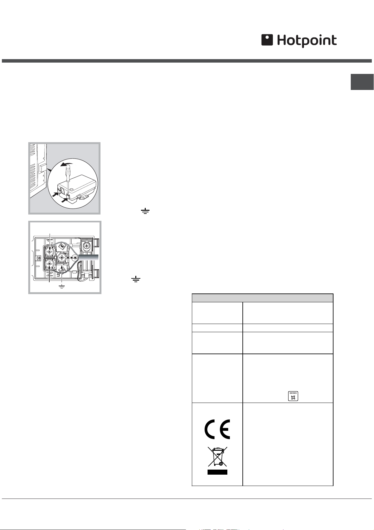
Electrical connection
Ovens equipped with a three-pole power supply
cable are designed to operate with alternating
current at the voltage and frequency indicated on
the data plate located on the appliance (see below).
Fitting the power supply cable
1. Open the terminal board by inserting a
screwdriver into the side tabs of the cover. Use the
screwdriver as a lever
by pushing it down to
open the cover (see
diagram).
2. Install the power
supply cable by
loosening the cable
clamp screw and the
three wire contact
screws L-N-
Connect the wires to
L
N
screw.
4. Close the cover of the terminal board.
Connecting the electricity supply cable to the
mains
Install a standardised plug corresponding to the
load indicated on the data plate (see table).
The appliance must be directly connected to the
mains using an omnipolar switch with a minimum
contact opening of 3 mm installed between the
appliance and the mains. The switch must be
suitable for the charge indicated and must comply
with current electrical regulations (the earthing wire
must not be interrupted by the switch). The supply
cable must be positioned so that it does not come
into contact with temperatures higher than 50°C at
any point.
The installer must ensure that the correct electrical
connection has been made and that it is fully
compliant with safety regulations.
Before connecting the appliance to the power
supply, make sure that:
the corresponding
terminals: the Blue wire
to the terminal marked
(N), the Brown wire to
the terminal marked (L)
and the Yellow/Green
wire to the terminal
marked
diagram).
3. Secure the cable by
fastening the clamp
.
(see
The appliance is earthed and the plug is compliant
with the law.
The socket can withstand the maximum power of
the appliance, which is indicated on the data
plate (see below).
The voltage is in the range between the values
indicated on the data plate (see below).
The socket is compatible with the plug of the
appliance. If the socket is incompatible with the
plug, ask an authorised technician to replace it.
Do not use extension cords or multiple sockets.
Once the appliance has been installed, the power
supply cable and the electrical socket must be
easily accessible.
The cable must not be bent or compressed.
The cable must be checked regularly and replaced
by authorised technicians only (see Assistance).
The manufacturer declines any liability should
these safety measures not be observed.
APPLIANCE SPECIFICATIONS
width 43.4 cm
Dimensions
Volume
Electrical
connections
ENERGY
LABEL
This appliance conforms to the
height 39.5 cm
depth 40.8 cm
70 l
voltage: 220 - 240 V~ 50Hz
maximum power absorbed
2600 W (see data plate)
Directive 2002/40/EC on the
label of electric ovens.
Standard EN 50304
Declared energy consumption
for Forced convection Class –
heating mode:
Gratin.
following European Economic
Community directives:
2006/95/EEC dated 12/12/06
(Low Voltage) and subsequent
amendments - 89/336/EEC
dated 03/05/89
(Electromagnetic Compatibility)
and subsequent amendments 93/68/EEC dated 22/07/93 and
subsequent amendments.
2002/96/EEC
GB
3
Description of
the appliance
GB
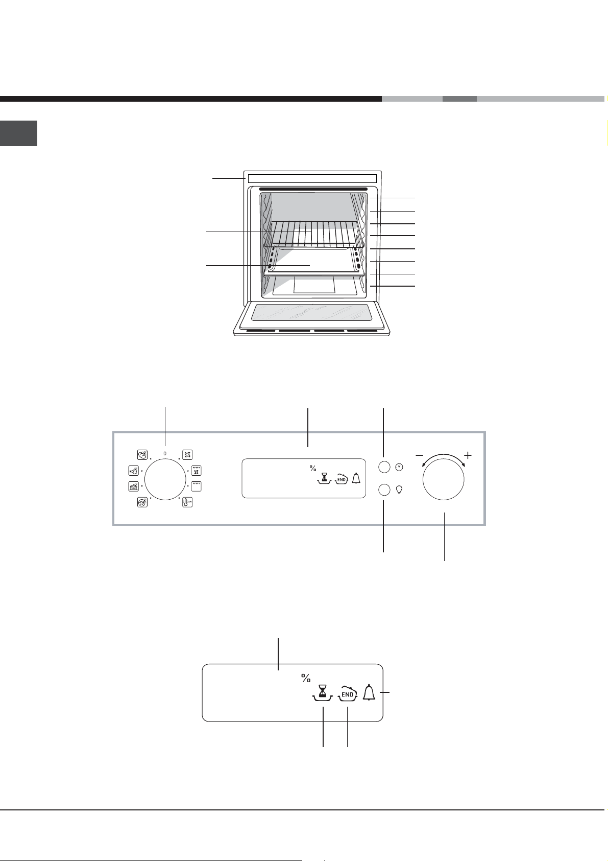
Overall view
DRIPPING PAN shelf
Control panel
Control panel
RACK shelf
FUNCTION
knob
DISPLAY
GUIDE RAILS
for the sliding racks
position 7
position 6
position D
position 5
position 4
position 3
position 2
position 1
SET TIMER
button
Display
TEMPERATURE and
TIME numerical digits
¡•OC
•• ••
¡•OC
:
•• ••
:
DURATION
icon
LIGHT
button
TIMER
icon
END OF COOKING
icon
SET
TEMPERATURE/
TIMER knob
4
Start-up and use
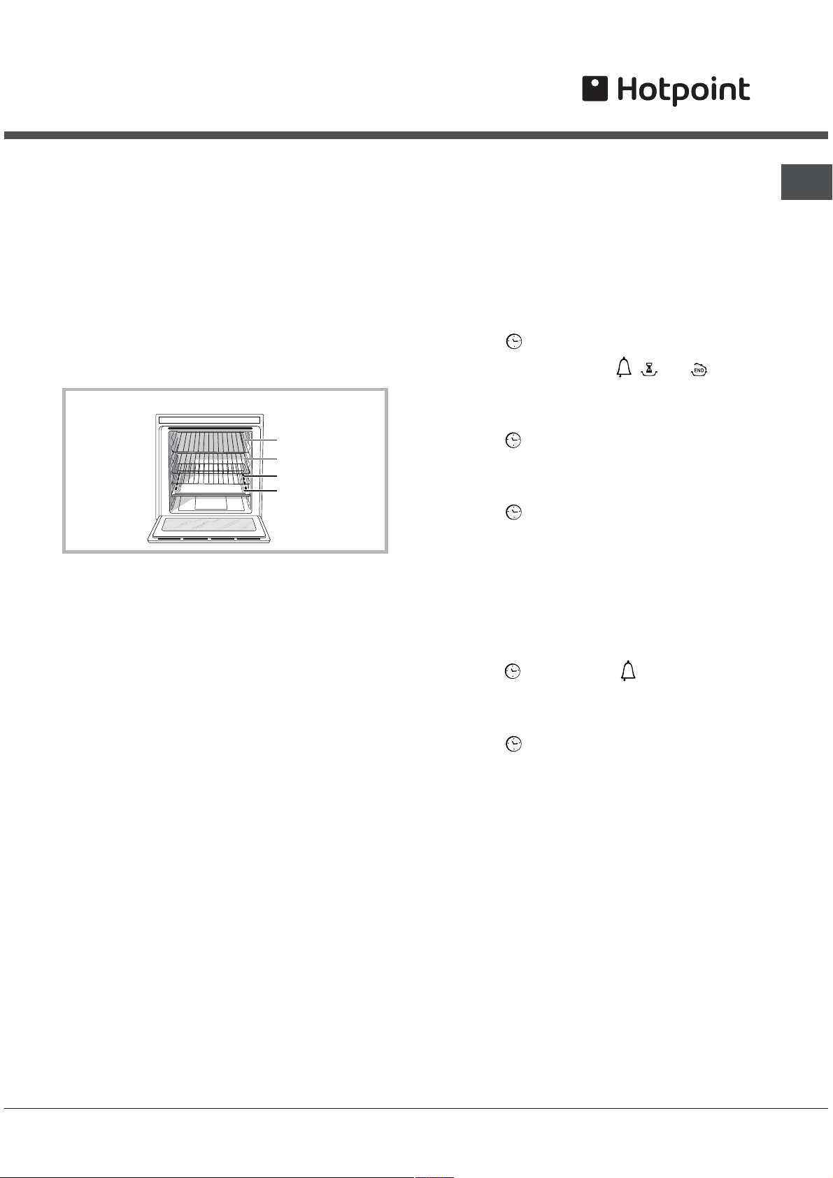
Oven structure
The Openspace oven has a capacity of 70 litres and
offers users the option of cooking on 4 shelves at
the same time or cooking large quantities which
would not necessarily be possible in a traditional
oven.
Thanks to the ExtraLarge Space, Openspace offers
10 cooking functions, 6 of which are universal and
suitable for any type of cooking, while the remaining
4 are automatic programmes which can be used to
achieve perfect results for any recipe.
ExtraLarge Space: cooking on 4 shelf levels
RACK
RACK
RACK
DRIPPING PAN
The first time you use your appliance, heat the
empty oven with its door closed at its maximum
temperature for at least half an hour. Make sure that
the room is well ventilated before switching the oven
off and opening the oven door. The appliance may
emit a slightly unpleasant odour caused by
protective substances used during the
manufacturing process burning away.
Never put objects directly on the bottom of the
oven; this will prevent the enamel coating from being
damaged.
Always place cookware on the rack(s) provided.
Oven light
When the oven is not in operation, the lamp can be
switched on at any time by pressing the light control
button.
Setting the clock
! This may only be set while the oven is switched
off.
1. Press the
flashes on the display and the
are switched off.
2. Turn the TIMER KNOB towards + and - to
adjust the hour value.
3. Press the
numerical digits on the DISPLAY begin to flash.
4. Turn the TIMER KNOB towards + and - to
adjust the minute value.
5. Press the
button until the first numerical digit
, and icons
button again so that the other two
button again to confirm.
Setting the timer
This function does not interrupt cooking and does
not affect the oven; it is simply used to activate the
buzzer when the set amount of time has elapsed.
1. Press the
digits on the DISPLAY begin to flash.
2. Turn the TIMER KNOB towards + and - to
adjust the minute value.
3. Press the
The display will then show the time as it counts
down. When this period of time has elapsed the
buzzer will be activated.
button until the icon and the three
button again to confirm.
GB
We suggest not opening the door when cooking
foodstuffs which require leavening, so as to not
compromise cooking results.
Cooling ventilation
In order to cool down the external temperature of the
oven, a cooling fan blows a stream of air between
the control panel and the oven door.
Once cooking is completed, the cooling fan
activates and deactivates automatically until the
oven has cooled down sufficiently.
Starting the oven
1. Select the desired cooking function by turning the
FUNCTION knob.
2. The oven will begin its preheating stage. The
temperature may be adjusted by turning the SET
TEMPERATURE knob.
3. When the buzzer sounds, the preheating stage is
complete: you may now place the food in the oven.
4. During cooking it is always possible to:
- Change the cooking function by turning the
FUNCTION knob.
- Adjust the temperature using the SET
TEMPERATURE knob (for the universal cooking
functions only).
5

GB
- Set a duration (for universal cooking functions only)
and the cooking end time.
- Stop cooking by turning the FUNCTION knob to the
0 position.
5. If a blackout occurs while the oven is already in
operation, an automatic system within the appliance
will reactivate the cooking function from the point at
which it was interrupted, as long as the temperature
has not dropped below a certain level. Programmed
cooking modes which have not started will not be
restored and must be reprogrammed.
Universal cooking functions
All functions have a default cooking temperature
which may be adjusted manually to a value between
40°C and 250°C as desired.
For the BARBECUE function, the default power level
value is indicated as a percentage (%) and may also
be adjusted manually.
LOW TEMPERATURE function
This type of cooking can be used for proving,
defrosting, preparing yoghurt, heating dishes at the
required speed and slow cooking at low
temperatures. The temperature options are: 40, 65
and 90 °C.
Spit roast (only available in certain models)
To operate the spit roast
function (see diagram)
proceed as follows:
1. Place the dripping
pan in position 1.
2. Place the rotisserie
support in position 3
and insert the spit in
the hole provided on
the back panel of the
oven.
MULTILEVEL function
All heating elements and the fan are activated. Since the
heat remains constant throughout the oven, the air cooks
and browns food in a uniform manner. A maximum of four
racks may be used at the same time. If you are using
several racks at the same time, we recommend you place
the dripping pan on the lower rack. If you are cooking on 4
levels at the same time, we recommend you place the
shelves on racks 3, 5 and 6 and the dripping pan on rack
1.
GRATIN function
The top heating element and the rotisserie spit
(where present) are activated and the fan begins to
operate. During part of the cycle the circular heating
element is also activated. This combination of
features increases the effectiveness of the
unidirectional thermal radiation provided by the
heating elements through the forced circulation of
the air throughout the oven.
This helps prevent food from burning on the surface
and allows the heat to penetrate right into the food.
Always cook in this mode with the oven door closed.
BARBECUE function
The top heating element and the rotisserie spit (where
present) are activated. By turning the SET
TEMPERATURE knob, the different power levels
which may be set will appear on the display; these
range between 5% and 100%. The high and direct
temperature of the grill is recommended for food
which requires a high surface temperature. Always
cook in this mode with the oven door closed.
3. Begin spit roast operation by selecting the
functions.
Automatic cooking functions
The temperature and cooking duration are pre-
set values, guaranteeing a perfect result every time -
automatically. These values are set using the
C.O.P.® (Programmed Optimal Cooking) system.
The cooking cycle stops automatically and the oven
indicates when the dish is cooked. The cooking
duration may be modified by a period of several
minutes, as specified in the description of the
individual functions below.
MEAT function
Use this function to cook veal, pork, lamb and beef.
Place the food inside the oven while it is still cold.
The dish may also be placed in a preheated oven. It
will only be possible to adjust the duration by -10/
+10 minutes.
BAKED CAKES function
This function is ideal for baking cakes. Place the
food inside the oven while it is still cold. The dish
may also be placed in a preheated oven. It will only
be possible to adjust the duration by -10/+15
minutes.
or
6

BREAD function
Use this function to make bread. Please see the
following chapter for the recipe and further details.
To achieve the best possible results, we recommend that
you carefully observe the instructions below:
Follow the recipe.
Remember to pour 150 g (150 ml) of cold water into
the baking tray, which should be placed in position
7.
Place the food inside the oven while it is still cold. If
you wish to place the food in the oven after it has
been preheated, immediately following a hightemperature cooking programme, the text Hot will
appear on the display until the temperature of the
oven has fallen to 40°. At this point it will be
possible to place the bread in the oven.
PIZZA function
Use this function to make pizza. Please see the
following chapter for further details. It will only be
possible to adjust the duration by -5/+12 minutes.
To achieve the best possible results, we recommend that
you carefully observe the instructions below:
Follow the recipe.
The weight of the dough should be between 350 g and
500 g.
Lightly grease the dripping pan and the baking trays.
Place the food inside the oven while it is still cold. If
you wish to place the food in the oven after it has
been preheated, immediately following a hightemperature cooking programme, the text Hot will
appear on the display until the temperature of the
oven has fallen to 120°. At this point it will be
possible to place the pizza in the oven.
Recipe for PIZZA:
Makes 3 or 4 pizzas: 1000 g flour, 500 ml water, 20 g salt,
20 g sugar, 100 ml olive oil, 20 g fresh yeast (or 2 sachets
of powder yeast)
Leavening at room temperature: 1 hour, or LOW
TEMPERATURE manual function set to 40°. Leave
to rise for approximately 30-45 minutes.
Place the food inside the oven while it is still cold.
Start the
PIZZA cooking mode.
Recipe for B READ (maximum amount of dough):
Ingredients:
1.3 kg flour
700 g water
25 g salt
50 g fresh bakers yeast or 4 sachets dried yeast
powder.
Method:
Mix the flour and salt in a large bowl.
Dilute the yeast in lukewarm water (approximately
35 degrees).
Make a small well in the mound of flour.
Pour in the water and yeast mixture.
Knead the dough by stretching and folding it over
itself with the palm of your hand for 10 minutes,
until it has a uniform consistency and is not too
sticky.
Form the dough into a ball shape, place it in a
large bowl and cover it with transparent plastic
wrap to prevent the surface of the dough from
drying out. Place the bowl in the oven, set to 40°
using the LOW TEMPERATURE manual function,
and leave to rise for approximately 3045
minutes. Alternatively, leave at room temperature
for approximately 1 hour (until the dough has
doubled in volume).
Break up the dough, kneading gently, and divide
it to create several loaves.
Place them on a sheet of baking paper (cut to the
same size as the inside of the dripping pan) on
top of the rack (or on 2 or 3 racks if you wish to
cook the loaves on different shelves) and dust
them lightly with flour.
Make a few incisions in the top using a sharp
blade.
Place the rack in the oven, on shelf level 2 if using
only one level, or place two racks on shelf levels 1
and 4 if using two levels, or place three racks on
shelf levels 1, 3 and 5 if using three levels.
Place the dripping pan on shelf lev
pour in 150 g cold water.
Place the food inside the oven while it is still cold.
Start the automatic function
When the cooking process has finished, leave the
loaves to rest on the rack until they have
completely cooled.
el 7 and
BREAD.
GB
7

GB
Programming cooking
A cooking function must be selected before
programming can take place.
Programming the cooking duration
1. Press the
icon and the three digits on the DISPLAY begin to
flash.
2. Turn the TIMER KNOB towards + and - to
adjust the duration.
3. Press the
4. When the set time has elapsed, the text END
appears on the DISPLAY, the oven will stop cooking
and a buzzer sounds.
For example: it is 9:00 a.m. and a time of 1 hour
and 15 minutes is programmed. The function will
stop automatically at 10:15 a.m.
button several times until the
button again to confirm.
Practical cooking advice
MULTILEVEL
Use positions 1, 3, 5 and 6.
Place the dripping pan at the bottom and the rack
at the top.
BARBECUE
Preheat the oven for 5 minutes.
Keep the oven door closed when cooking in this
mode.
Place the dripping pan on shelf level 3. Place the
rack in a position between 4 and 7, depending on
how bulky the food is, and make sure the food is
in the centre of the rack. Examples: beef ribs
should be cooked on shelf level 4 and bacon on
shelf level 6 or 7.
Setting the end time for a cooking mode
A cooking duration must be set before the cooking
end time can be scheduled.
1. Follow steps 1 to 3 to set the duration as detailed
above.
2. Next, press the
the three numerical digits on the DISPLAY begin to
flash.
3. Turn the TIMER KNOB towards + and - to
adjust the hour value.
4. Press the
numerical digits on the DISPLAY begin to flash.
5. Turn the TIMER KNOB towards + and - to
adjust the minute value.
6. Press the
7. When the set time has elapsed, the text END
appears on the DISPLAY, the oven will stop cooking
and a buzzer sounds.
Programming has been set when the
icons flash. The DISPLAY shows the cooking end
time and the cooking duration alternately.
To cancel programming, turn the FUNCTION knob to
the 0 position.
button until the icon and
button again so that the other two
button again to confirm.
and
PIZZA or FOCACCIA
Use a light aluminium tray with a maximum
diameter of 30 cm, placing it on top of the rack
supplied.
If the pizza has a lot of toppings, we recommend
adding the mozzarella cheese on top of the pizza
halfway through the cooking process.
8

g
Cooking advice table for ovens with an ExtraLarge Space cavity
Function
Multilevel*
Barbecue*
temperature
Automatic
Automatic
Automatic
Automatic
Gratin*
Low
Bread (see recipe)
bread
roast
baked
cakes
pizza
Pies / Tarts
Cream puffs
Pizza
Biscuits
Pastries
Crème caramel
(bain-marie)
Panettone 1 1 or 2 Yes 160 45-60
Sponge cake mad e
with yoghurt
Sponge cake
Large cut of meat 1 1 2 Yes 160 90-240
Rotisserie 1 2 3 No 200 35-75
Gratin 1 3 or 4 No 190 40-60
Large roast 1 1 2 No 200 90-120
Large roast game 1 1 2 No 200 90-120
Beef ribs 1 3 4 or 5 Yes 100% 20-30
Sausages 1 3 5 to 7 Yes 100% 10-20
Pork ribs 1 3 5 to 7 Yes 100% 15-25
Bacon 1 3 5 to 7 Yes 100% 3-6
Proving / Defrosting
White meringues 4 1 3 5 6 No 65 8-12 hours**
Meat / Fish 3 1 3 5 No 90 90-180**
Roasts
Desserts
Pizza (see recipe)
Foods
Weight
(in kg)
Cook on
no. of
shelves
No.
1
1
1
1
1
1
1 2 2 or 3
1
1 2 No 40
2
2
2
1 2 3 No 60-90**
1 2 2
1
Dripping
pan
2
3
4
2
3
4
2
3
4
2
3
4
2
3
2
3
2
3
1
2
3
2
3
4
2 or 3
1 to 2
1
1
2 or 3
1 to 2
1
1
2 or 3
1 to 2
1
1
2 or 3
1 to 2
1
1
2 or 3
2
1
2 or 3
2
1
1
2 or 3
2
1
7***
7***
7***
2
2
2
1
1
Rack position
Rack 1 Rack 2 Rack 3
3 to 5
3
3
3 to 5
3
3
3 to 5
3
3
3 to 5
3
3
5
4
5
4
4 or 5
5
4
2
1
1
5
5
3
3
* The cooking times listed a bove are intended as guidelines only and may be modified according to personal tastes. Oven preheating times are set
as standard and may not be modified manually.
** The duration of the automatic cooking functions are set by default. The values in the table refer to the mi nimum and ma ximum duration, which
may be modified by the user, taking the default value as a starting point.
*** As stated in the recipe, pour 150
water into the dripping pan.
5
5
5
5
5
5
5
5
6
6
Yes
6
4
3
No
5
5
Preheating Recommended
6
6
6
6
Yes
Yes
Yes
5
6
Yes
Yes
Yes
Yes
Yes
Yes
Yes
Yes
Yes
Yes
Yes
Yes
Yes
Yes
Yes
Yes
Yes
Yes
Yes
Yes
Yes
Yes
Yes
No
No
No
No
No
No
No
No
temperature
(°C)
180
180
180
180
190
190
190
190
220
220
220
220
180
180
180
180
200
200
200
170
170
170
160
160
190
190
190
35-60**
23-30**
Cooking
duration
(minutes)
30-40
35-45
40-50
45-55
25-35
25-35
30-40
30-40
15-25
20-30
25-35
30-40
15-25
15-25
20-30
20-30
30-40
35-45
40-50
35-45
35-45
40-50
60-75
60-75
30-35
35-40
40-45
35-60**
25-35**
30-35**
35-40**
GB
9

Precautions and tips
GB
This appliance has been designed and
manufactured in compliance with international safety
standards. The following warnings are provided for
safety reasons and must be read carefully.
General safety
The appliance was designed for domestic use
inside the home and is not intended for
commercial or industrial use.
The appliance must not be installed outdoors,
even in covered areas. It is extremely dangerous
to leave the appliance exposed to rain and
storms.
When moving or positioning the appliance, always
use the handles provided on the sides of the
oven.
Do not touch the appliance with bare feet or with
wet or damp hands and feet.
The appliance must be used by adults only for the
preparation of food, in accordance with the
instructions provided in this booklet.
Do not touch the heating elements or certain parts
of the oven door when the appliance is in use;
these parts become extremely hot. Keep children
well away from it and do not touch the hot parts
yourself.
Ensure that the power supply cables of other
electrical appliances do not come into contact
with the hot parts of the oven.
The openings used for the ventilation and
dispersion of heat must never be covered.
Always grip the oven door handle in the centre:
the ends may be hot.
Always use oven gloves when placing cookware
in the oven or when removing it.
Do not use aluminium foil to line the bottom of the
oven.
Do not place flammable materials in the oven: If
the appliance is switched on accidentally, the
materials could catch fire.
Always make sure the knobs are in the l/
position when the appliance is not in use.
When unplugging the appliance, always pull the plug
from the mains socket; do not pull on the cable.
Never perform any cleaning or maintenance work
without having disconnected the appliance from
the electricity mains.
If the appliance breaks down, under no
circumstances should you attempt to perform the
repairs yourself. Repairs carried out by
inexperienced individuals may cause injury or
¡
further malfunctioning of the appliance. Contact a
Service Centre (see Assistance).
Do not rest heavy objects on the open oven door.
The appliance should not be operated by people
(including children) with reduced physical,
sensory or mental capacities, by inexperienced
individuals or by anyone who is not familiar with
the product. These individuals should, at the very
least, be supervised by someone who assumes
responsibility for their safety or receive
preliminary instructions relating to the operation of
the appliance.
Do not let children play with the appliance.
Disposal
When disposing of packaging material: observe
local legislation so that the packaging may be
reused.
The European Directive 2002/96/EC relating to
Waste Electrical and Electronic Equipment
(WEEE) states that household appliances should
not be disposed of using the normal solid urban
waste cycle. Exhausted appliances should be
collected separately in order to optimise the cost
of re-using and recycling the materials inside the
machine, while preventing potential damage to
the atmosphere and to public health. The
crossed-out dustbin is marked on all products to
remind the owner of their obligations regarding
separated waste collection. For further information
relating to the correct disposal of exhausted
household appliances, owners may contact the
relevant public service or their local dealer.
Respecting and conserving the
environment
You can help to reduce the peak load of the
electricity supply network companies by using the
oven in the hours between late afternoon and the
early hours of the morning. The cooking mode
programming options, the delayed cooking
mode (see Cooking modes) in particular, enable
the user to organise their time efficiently.
Always keep the oven door closed when using the
BARBECUE and GRATIN modes: this will achieve
improved results while saving energy
(approximately 10%).
Check the door seals regularly and wipe them
clean to ensure they are free of debris so that
they adhere properly to the door, thus avoiding
heat dispersion.
10

Care and maintenance
Switching the appliance off
Disconnect your appliance from the electricity
supply before carrying out any work on it.
Cleaning the appliance
The stainless steel or enamel-coated external
parts and the rubber seals may be cleaned using
a sponge that has been soaked in lukewarm water
and neutral soap. Use specialised products for
the removal of stubborn stains. After cleaning,
rinse and dry thoroughly. Do not use abrasive
powders or corrosive substances.
The inside of the oven should ideally be cleaned
after each use, while it is still lukewarm. Use hot
water and detergent, then rinse well and dry with
a soft cloth. Do not use abrasive products.
All accessories - with the exception of the sliding
racks - can be washed like everyday crockery,
and are even dishwasher safe.
Never use steam cleaners or pressure cleaners on
the appliance.
Cleaning the oven door
Clean the glass part of the oven door using a
sponge and a non-abrasive cleaning product, then
dry thoroughly with a soft cloth. Do not use rough
abrasive material or sharp metal scrapers as these
could scratch the surface and cause the glass to
crack.
For more thorough cleaning purposes, the oven door
may be removed:
1. Open the oven door fully (see diagram).
2. Use a screwdriver to lift up and turn the small
levers F located on the two hinges (see diagram).
Inspecting the seals
Check the door seals around the oven at regular
intervals. If the seals are damaged, please contact
your nearest After-sales Service Centre (see
Assistance). We recommend that the oven is not
used until the seals have been replaced.
Replacing the light bulb
To replace the oven light bulb:
1. Remove the
Oven
compartment
glass cover of the
lamp-holder.
2. Remove the
Lamp
light bulb and
replace it with a
similar one:
Glass cover
halogen lamp
voltage 230 V,
wattage 25 W,
cap G 9.
3. Replace the glass cover (see diagram).
Do not touch the light bulb directly with your
hands.
Sliding rack kit assembly
To assemble the sliding racks:
1. Remove the two frames,
lifting them away from the
spacers A (see figure).
A
GB
F
3. Grip the door on the two
outer sides and close it
approximately half way. Pull
the door towards you lifting it
out of its seat (see diagram).
To replace the door, reverse
this sequence.
Left
guide rail
B
Right guide
rail
Direction
C
of extraction
with the sliding rack. Paying
attention to the direction in
which the sliding rack is to be
extracted, position joint B and
then joint C on the frame.
3. Secure the two frames with
the guide rails using the holes
provided on the oven walls
(see diagram). The holes for
2. Choose which shelf to use
D
the left frame are situated at
the top, while the holes for the
right frame are at the bottom.
4. Finally, fit the frames on the spacers A.
11

GB
12

GB
13

GB
14

After Sales Service
No one is better placed to care for your Hotpoint appliance during the course of its working life than
us - the manufacturer.
Essential Contact Information
Hotpoint Service
We are the largest service team in Europe offering you access to 400 skilled telephone advisors and
1100 fully qualified engineers on call to ensure you receive fast, reliable, local service.
UK: 08709 066 066
Republic of Ireland: 0818 313 413
www.hotpointservice.co.uk
Please note: Our advisors will require the following information:
Model number:
Serial number:
Parts and Accessories
We supply a full range of genuine replacement parts as well as accessory products that protect and
hygienically clean your appliance to keep it looking good and functioning efficiently throughout its life.
GB
UK: 08709 077 077
Republic
www.hotpointservice.co.uk
We want to give you additional benefits of Hotpoint ownership. To activate your free 5 year parts
guarantee you must register your appliance with us.
Republic of Ireland: 01 230 0800
www.hotpointservice.co.uk
Indesit Company UK Ltd. Morley Way, Peterborough, PE2 9JB
Indesit Company Unit 49 Airways Industrial Estate,Dublin 17
of Ireland: 0818 313 413
Appliance Registration
UK: 0870 6092094
Recycling & Disposal Information
As part of Hotpoint's continued commitment to helping the environment, Hotpoint reserves the right to use
quality, recycled components to keep down customer costs and minimise material wastage.
Please dispose of packaging and old appliances carefully. To minimise the risk of injury to children,
remove the door, plug and cut the
separately to ensure that the appliance can no longer be plugged into a mains socket, and the door cannot
be locked shut.
mains cable off flush with the appliance. Dispose of these parts
15

12/2008 - 195072447.00
XEROX FABRIANO
GB
Guarantee
12 Months Parts and Labour Guarantee
Your appliance has the benefit of our manufacturers guarantee, which covers the cost of breakdown
repairs for twelve months from the date of purchase.
This gives you the reassurance that if, within that time, your appliance is proven to be defective
because of either workmanship or materials, we will, at our discretion, either repair or replace the
appliance at no cost to you.
This guarantee is subject to the following conditions:
- The appliance has been installed and operated correctly and in accordance with our
operating and maintenance instructions.
- The appliance is used only
- The appliance has been used for normal domestic purposes only.
- The appliance has not been altered, serviced, maintained, dismantled, or otherwise
interfered with by any person not authorised by us.
- Any repair work must be undertaken by us or our
- Any parts removed during repair work or any appliance that is replaced become our property.
- The appliance is used in the United Kingdom or Republic of Ireland.
The guarantee does not cover:
on the electricity or gas supply printed on the rating plate.
appointed agent.
- Damage resulting from transportation, improper use, neglect or interference or as a result
of improper installation.
- Replacement
cables, batteries, light bulbs, fluorescent tubes and starters, covers and filters.
- Replacement of any removable parts made of glass or plastic.
THIS GUARANTEE WILL NOT APPLY IF THE APPLIANCE HAS BEEN USED IN COMMERCIAL
OR NON-
Hotpoint also offers you a free 5 year parts guarantee. This additional guarantee is conditional on you
registering your appliance with us and the parts being fitted by one of our authorised engineers.
There will be a charge for our engineer's time. To activate the
We offer a selection of repair protection plans that enable you to fully cover yourself against the
expense of repair bills for the life of your policy. To find the ideal
DOMESTIC PREMISES.
of any consumable item or accessory . These include but are not limited to: plugs,
5 Year Parts Guarantee
extra parts warranty on your appliance,
simply call our registration line on 0870 6092094 (ROI 01 230 0800).
Extended Guarantees
plan for you please call our advice
line on 08709 088 088 (ROI 01 230 0233).
Free Helpdesk Service
We have a dedicated team who can provide free advice and assistance with your appliance if you
experience any technical difficulties within the first 90 days of ownership. Simply call our Hotpoint
Service Hotline
to arrange for an engineer to call. If we cannot resolve the technical problem we will replace your
16
on 08709 066 066 (ROI 0818 313 413) for telephone assistance, or, where necessary,
machine or, if you prefer, give you your money back.
 Loading...