


PCN 642 T/IX/A
PNC 722 T/D2/IX/A
PCN 732 T/D2/IX/A
 English
Operating Instructions
HOB
Contents
Operating Instructions,1 Warnings,2 Assistance,5
Description of the appliance,6 Installation,8
Start-up and use,12 Precautions and tips,12 Maintenance and care,13 Troubleshooting,13
 Français
Mode d’emploi
TABLE DE CUISSON
Sommaire
Mode d’emploi,1 Avertissements,2 Assistance,5
Description de l’appareil,6 Installation,15
Mise en marche et utilisation,19 Précautions et conseils,19 Nettoyage et entretien,20 Anomalies et remèdes,21
 Portuges
Instruções para a utilização
PLANO
Índice
Instruções para a utilização,1 Advertências,3 Assistência,5
Descrição do aparelho,6 Instalação,22
Início e utilização,26 Precauções e conselhos,26 Manutenção e cuidados,27 Anomalias e soluções,28

HOB
135 6
29
33 333434
ليغشتلاتاميلعت
نيخستفر
تايوتحملا
1،ليغشتلاتاميلعت
3،تاريذحت
5،ةدعاسملا
7،زاهجلافصو
35 ،بيكرتلا
38،مادختسلااوليغشتلاءدب
38 ،حئاصنلاورذحلالئاسو
40 ،ةيانعلاوةنايصلا
40،اهلحولكاشملافاشكتسا

|
|
|
|
|
|
|
|
|
|
|
|
|
|
|
|
|
|
Warnings |
Avertissements |
||||
WARNING: The appliance and its accessible parts become hot during use. Care should be taken to avoid touching heating elements. Children less than8 years of age shall be kept away unless continuously supervised. This appliance can be used by children aged from 8 years and above and persons with reduced physical, sensory or mental capabilities or lack of experience and knowledge if they have been given supervision or instruction concerning use of the appliance in a safe way and understand the hazards involved. Children shall not play with the appliance. Cleaning and user maintenance shall not be made by children without supervision.
WARNING: Unattended cooking on a hob with fat or oilcanbedangerousandmayresultinfire.NEVER try to extinguish a fire with water, but switch off the appliance and then cover flame e.g. with a lid or a fire blanket.
WARNING:Dangeroffire:donotstoreitemsonthe cooking surfaces.
Never use steam cleaners or pressure cleaners on the appliance.
Remove any liquid from the lid before opening it. Do not close the glass cover (if present) when the gas burners or electric hotplates are still hot.
The appliance is not intended to be operated by means of an external timer or separate remote control system.
CAUTION: the use of inappropriate hob guards can cause accidents.
2
ATTENTION : Cet appareil ainsi que ses parties accessibles deviennent très chauds pendant leur fonctionnement.Ilfaut faire attention à ne pas toucher les éléments chauffants. Ne pas faire approcher les enfants de moins de 8 ans à moins qu’ils ne soient sous surveillance constante. Le présent appareil peut être utilisé par des enfants de plus de 8 ans et par des personnes présentant des capacités physiques, sensorielles ou mentales réduites ou n’ayant pas l’expérience ou les connaissances indispensables, à condition qu’ils soient sous bonne surveillance ou qu’ils aient reçu les instructions nécessaires pour une utilisation de l’appareil en toute sécurité et à condition qu’ils se rendent compte des dangers encourus. Les enfants ne doivent pas jouer avec l’appareil. Les opérations de nettoyage et d’entretien ne doivent pas être effectuées par des enfants non surveillés.
ATTENTION : Laisser un récipient de cuisson avec de l’huile ou de la graisse sur un foyer est dangereux et risque d’entraîner un incendie. Il ne faut JAMAIS essayer d’éteindre une flamme ou un incendie avec de l’eau ! Il faut éteindre l’appareil et couvrir la flammeavecuncouvercle,parexemple,ouavecune couverture anti-feu.
ATTENTION : Risque d’incendie : ne pas laisser d’objets sur les surfaces de cuisson.
Ne jamais nettoyer l’appareil avec des nettoyeurs vapeur ou haute pression.
Essuyer tout liquide pouvant se trouver sur le couvercle avant de l’ouvrir. Ne pas abaisser le couvercle en verre (s’il y en a un) tant que les brûleurs gaz ou la plaque électrique sont chauds.
Cet appareil ne peut pas être allumé au moyen d’un temporisateur extérieur ou d’un système de commande à distance séparé.
ATTENTION : l’utilisation de protections de table inappropriées peut causer des incendies.
Advertências
ATENÇÃO: Este aparelho e as suas partes acessíveis aquecem muito durante a utilização. É preciso ter atenção e evitar tocar os elementos que aquecem. Manter afastadas as crianças com menos de 8 anos, caso não estejam a ser vigiadas. O presente aparelho pode ser utilizado por crianças com mais de 8 anos e por pessoas com capacidades físicas, sensoriais ou mentais reduzidas ou com pouca experiência e conhecimentos, caso sejam adequadamente vigiadas ou caso tenham recebido instruções em relação ao uso do aparelho de forma segura e tenham conhecimento dos perigos associados. As crianças não devem brincar com o aparelho. As operações de limpeza e manutenção não devem ser efectuadas por crianças sem vigilância.
ATENÇÃO:Deixarumfogãocomgorduraeóleosem vigilância pode ser perigoso e provocar um incêndio. NUNCA tente apagar as chamas com água. É necessário desligar o aparelho e cobrir as chamas com uma tampa ou com uma manta ignífuga.
ATENÇÃO: Risco de incêndio: não deixe objectos sobre as superfícies de cozedura.
Nunca utilize equipamento de limpeza a vapor ou de alta pressão para limpar o aparelho.
Elimine os líquidos presentes na tampa antes de abri-la. Não feche a tampa de vidro (se presente) se os queimadores ou achapa eléctrica ainda estiverem quentes.
O aparelho não é destinado a ser colocado em funcionamento por meio de um temporizador externo ouporumsistemadecomandoàdistânciaseparado.
ATENÇÃO: O uso de protecções do plano inadequadas pode causar incidentes.
8 8
盖住火焰。
تاريذحت
.مادختسلااءانثأادجً ةنخاسةسوململاهءازجأعيمجوزاهجلااذهحبصي:هبتنا لقلأالافطلأاداعبإبمق.نيخستلارصانعةسملامبنجتورذحلايخوتبجي
.ةرمتسملامهتبقارمةلاحيفلاإزاهجلانعتاونس8 نسنم امكزاهجلااذهمادختسابتاونس 8 نس نم ربكلأا لافطلأا موقي نأ نكمي ةيلقع وأ ةيسحِ وأ ةيدسج تاردق يوذ صاخشأ لبقِ نم همادختسا نكمي متت املاط ،زاهجلاب ةفرعملاو ةربخلا دقتفت صاخشأ لبقِ نم وأ ؛ةدودحم لبقِنمهسفنزاهجلامادختسابقلعتياميفاديجً مهميلعتمتيوأةيانعبمهتبقارم ببستيدقيتلارطاخملاعيمجباملعًمهتطاحإومهتملاسنعلوئسمصخش نأبجيلا.زاهجلابمهثبعمدعنمدكأتلللافطلأاةبقارمبجي.زاهجلااهب
.ةبقارملاتحتلاإزاهجلاةنايصوفيظنتلاتايلمعبلافطلأاموقي
دقامكرطخردصمةبقارمنوددقوملابتويزومحشكرتنوكيدق:هبتنا
.قئارحثودحيفببستي
3

موقت نأ بجي لب ،ءاملا ةطساوب قيرح/ةلعش ءافطإ ةلواحم دبأاً بجي لا ةطساوبوأءاطغةطساوبلاثملاليبسىلعةلعشلاةيطغتوزاهجلاءافطإب
.لاعتشلالةداضمةيناطب
ءاطغلاقلغتلا.يهطلاحطسأىلعءايشأكرتتلا:قئارحثودحرطخ:هبتنا
.ةنخاستلازاموأةلعتشمقراحملانوكتامنيب)دجون(
فيظنت تلاآ وأ راخبلاب فيظنت تلاآ ةطساوب زاهجلا فيظنتب ادبأً مقت لا
.يلاعلاطغضلابلمعت
.هحنفلبقءاطغلانملئاسلاجرخأ
وأةيجراخينمزمكحتةدحوةطساوبهليغشتمتيلصصخمُريغزاهجلانإ
.زاهجلانعلصفنمدعبىلعنممكحتماظن
ىلإ دقوملا حطس ةياقو تادحول حيحصلا ريغ مادختسلاا يدؤي دق :هبتنا
.قئارحثودح
4
Assistance
Communicating:
•the type of problem encountered.
•appliance model (Mod.)
•serial number (S/N)
This information is found on the data plate located on the appliance and/or on the packaging.
! Never use unauthorised technicians and never accept replacement parts which are not original.
ةدعاسملا
:لاصتلاا
.هدمآدوجوبلاکشاعون |
• |
.)Mod.(هاگتسدلدم |
• |
.)S/N(نآلایرسهرامش |
• |
.ةوبعلاىلعوأ/وزاهجلاىلعةدوجوملاتانايبلاةحولىلعاهدجتنأنكميتامولعملاهذه
.ةيلصلأا ريغ رايغلا عطق امئاد ضفراو ،ادبأ نيلهؤملا ريغ نيينفلا يعدتست لا!
Assistance
Indiquez-lui :
•le type d’anomalie
•le modèle de votre appareil (Mod.)
•son numéro de série (S/N)
Ces informations figurent sur la plaquette signalétique apposée sur votre appareil et/ou sur son emballage.
! Ne faites jamais appel à des techniciens non agréés et refusez toujours l’installation de pièces détachées non originales.
Assistência
Comunique:
•o tipo de avaria
•o modelo da máquina (Mod.)
•o número de série (S/N)
Estas últimas informações encontram-se na placa de identificação situada no aparelho e/ou na embalagem.
! Nunca recorra a técnicos não autorizados e sempre recuse a instalação de peças de reposição não originais.
•(Mod.)
•(S/N)
/
!
5
|
|
|
|
|
|
|
|
|
|
|
|
|
|
|
|
|
|
|
|
|
|
|
|
|
|
|
|
|
|
Description of the appliance |
Descrição do aparelho |
||||||||
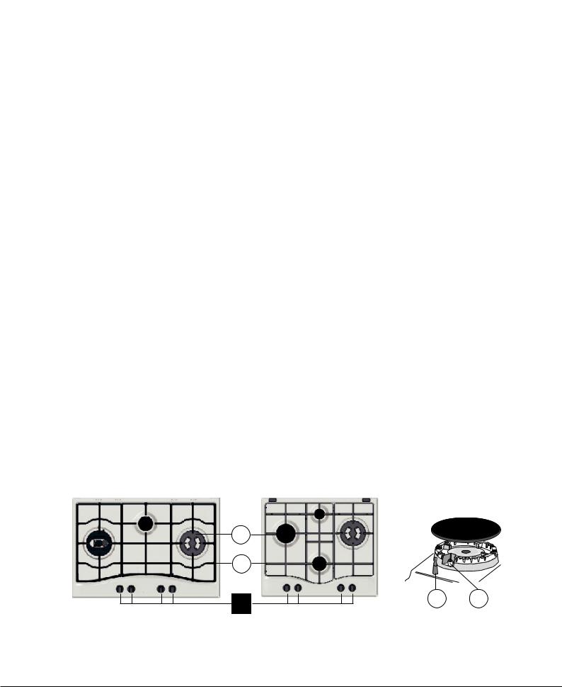
Overall view |
Vista de conjunto |
||||||||
1. |
Support Grid for COOKWARE |
1. |
Grades de suporte para RECIPIENTES DE COZEDURA |
||||||
2. |
GAS BURNERS |
2. |
QUEIMADORES DE GÁS |
||||||
3. |
Control Knobs for GAS BURNERS |
3. |
Manípulos de comando dos QUEIMADORES A GÁS |
||||||
4. |
Ignition for GAS BURNERS |
4. |
Vela para acender osQUEIMADORES A GÁS |
||||||
5. |
SAFETY DEVICES |
5. |
DISPOSITIVO DE SEGURANÇA |
||||||
• |
GASBURNERSdiffer in sizeand power. Use the diameter of the cookware |
• |
Os QUEIMADORES sãodediferentestamanhosepotências.Escolhao |
||||||
|
to choose the most appropriate burner to cook with. |
|
mais adequado ao diâmetro do recipiente a ser utilizado. |
||||||
• |
Control Knobs for GAS BURNERS adjust the size of the flame. |
• |
Selectores de comando dos QUEIMADORES A GÁS para a regulação |
||||||
• |
GAS BURNER IGNITION enablesaspecificburnertobelitautomatically. |
|
da chama. |
||||||
• |
SAFETY DEVICE stops the gas flow if the flame is accidentally |
• |
Vela para acender osQUEIMADORES A GÁS permite o acendimento |
||||||
|
extinguished. |
|
automático do queimador escolhido. |
||||||
|
|
|
• |
DISPOSITIVO DE SEGURANÇA no caso em que a chama se apague |
|||||
|
|
|
|
acidentalmente, interrompe a saída do gás. |
|||||
|
|
|
|
|
|
|
|
||
|
|
|
|
|
|
|
|
|
|
Description de l’appareil |
|
|
|
|
|
|
|||
|
|||||||||
Vue d’ensemble |
|||||||||
1. |
Grilles support de CASSEROLES |
|
|
|
|
|
|
||
2. |
BRÛLEURS À GAZ |
|
|||||||
3. |
Manettes de commande des BRÛLEURS GAZ |
1. |
|
||||||
4. |
Bougie d’allumage des BRÛLEURS GAZ |
2. |
|
||||||
5. |
DISPOSITIF DE SÉCURITÉ |
3. |
|
||||||
• |
BRÛLEURS GAZ ils ont plusieurs dimensions et puissances. Choisissez |
4. |
|
||||||
5. |
|
||||||||
|
celui qui correspond le mieux au diamètre de votre casserole. |
|
|
|
|
|
|
||
• |
Manettes de commande des BRÛLEURS GAZ pour le réglage de la |
• |
|
||||||
|
flamme. |
|
|
||||||
• |
La bougie d’allumage des BRÛLEURS GAZ permet l’allumage |
• |
|
||||||
|
automatique du brûleur sélectionné. |
• |
|
||||||
• |
DISPOSITIF DE SÉCURITÉ encasd’extinctionaccidentelledelaflamme, |
• |
|
||||||
|
coupez immédiatement l’arrivée du gaz. |
|
|
|
|
|
|
||
2
1
3 |
5 |
4 |
|
|
6
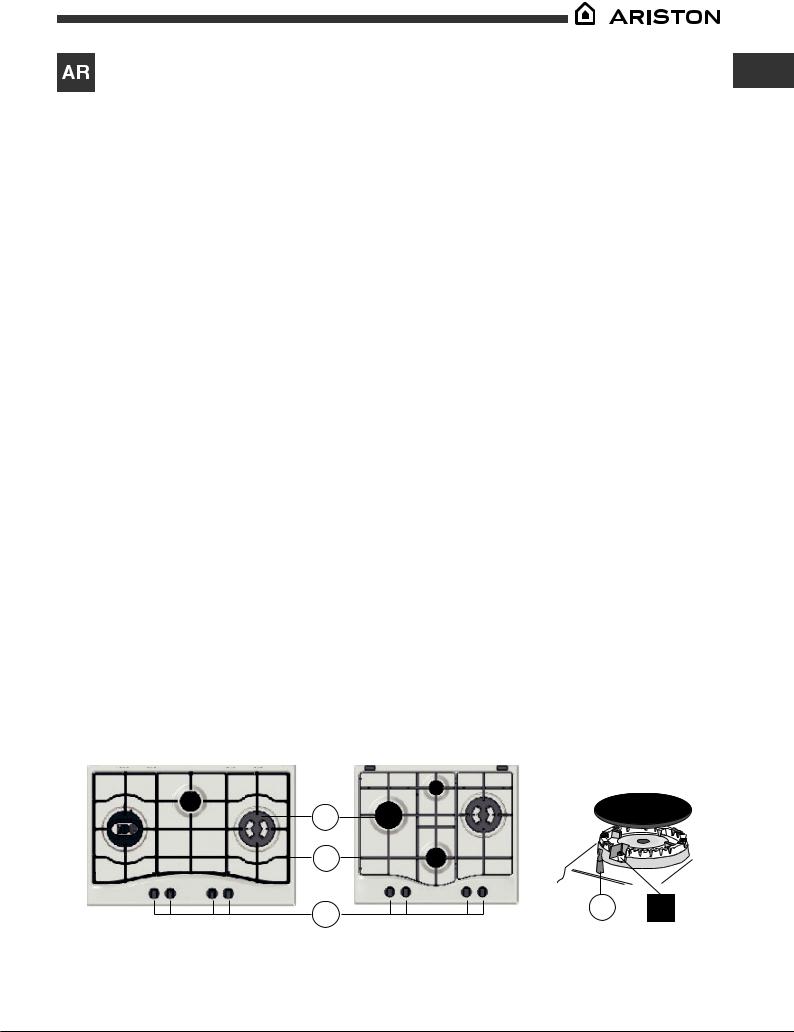
زاهجلافصو
ةماعةرظن
يهطلايناولأمعدةكبش1 .
زاغلابةلماعلعاشم2 . زاغلابةلماعلالعاشملايفمكحتلاضباقم3 .
زاغلابةلماعلالعاشملالاعشإةعمش4 .
ناملأازاهج5 .
يناولأارطقلُ ةمئلامرثكلأالعشملارايتخابجي.ةردقلاوداعبلأاثيحنمفلتختزاغلابةلماعلعاشم•
.اهمادختسامتييتلا
.ةلعشلاطبضبموقتزاغلابةلماعلالعاشملايفمكحتلاضباقم•
.هرايتخاقباسلالعشملليتاذلالاعشلإابحمستزاغلابةلماعلالعاشملالاعشإةعمش•
.ةلعشلليضرعلاليغشتلافاقيإةلاحيفزاغلاجورخعطقيناملأازاهج•
2
1
3
GB
5 4
7

GB Installation
!Before operating your new appliance please read this instruction booklet carefully. It contains important information for safe use, installation and care of the appliance.
!Please keep these operating instructions for future reference. Pass them on to possible new owners of the appliance.
Positioning
!Keep packaging material out of the reach of children. It can become a choking or suffocation hazard (see Precautions and tips).
!Theappliancemustbeinstalledbyaqualifiedprofessionalaccordingtothe instructions provided. Incorrect installation may cause harm to people and animals or may damage property.
!This unit may be installed and used only in permanently ventilated rooms in accordance with current national regulations. The following requirements must be observed:
• The room must be equipped with an air extraction system that expels any combustion fumes. This may consist of a hood or an electric fan that automatically starts each time the appliance is switched on.
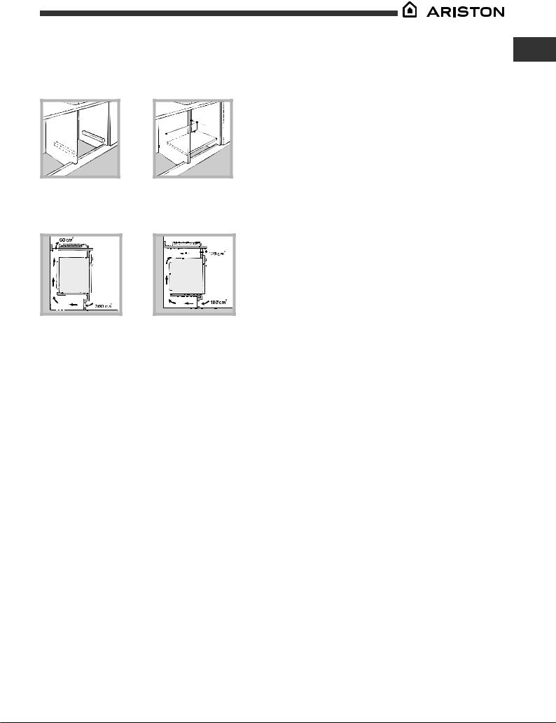
Fitting the appliance
The following precautions must be taken when installing the hob:
•Kitchen cabinets adjacent to the appliance and taller than the top of the hob must be at least 200 mm from the edge of the hob.
•Hoods must be installed according to their relative installation instruction manualsandataminimumdistanceof650mmfromthehob(seefigure).
•Place the wall cabinets adjacent to the hood at a minimum height of 420 mm from the hob (see figure).
|
|
|
|
|
|
|
|
|
|
If the hob is installed beneath a wall cabinet, |
|
|
|
|
|
|
|
|
|
|
|
|
|
|
|
|
|
|
|
|
|
the latter must be situated at a minimum of 700 |
|
|
|
|
|
|
|
|
|||
|
|
|
|
|
|
|
|
|||
650mm min. |
|
600mm min. |
|
420mm min. |
|
|
mm above the hob. |
|||
|
|
|
||||||||
|
|
|||||||||
|
|
|
|
|
|
|
|
|||
|
|
|
|
|
|
|
|
|
|
|
|
|
|
|
|
|
|
|
|
|
|
|
|
|
|
|
|
|
|
|
|
|
|
|
|
|
|
|
|
|
|
|
|
•Theinstallationcavityshouldhavethedimensionsindicatedinthefigure.
Fastening hooks are provided, allowing you to fasten the hob to tops that are between 20 and 40 mm thick. To ensure the hob is securely fastened to the top, we recommend you use all the hooks provided.
|
|
|
555 mm |
|
|
|
|
|
|
55 |
mm |
|
|
mm |
|
|
|||
|
|
|
||
|
|
475 |
||
|
|
|
||
|
|
|
|
|
|
|
|
|
|
|
|
|
|
|
|
|
|
|
|
|
|
|
|
|
|
|
|
|
|
|
|
|
|
|
|
|
|
|
|
|
|
|
|
|
|
|
|
|
|
|
|
|
|
|
|
|
|
|
|
|
|
|
|
|
In a chimney stack or branched flue. |
Directly to |
|
|||||||||
(exclusively for cooking appliances) |
the Outside |
|
|||||||||
•The room must also allow proper air circulation, as air is needed for combustiontooccurnormally.Theflowofairmustnotbelessthan2m3/h per kW of installed power.
|
The air circulation system may take air directly |
|
from the outside by means of a pipe with an |
|
inner cross section of at least 100 cm2; the |
|
opening must not be vulnerable to any type |
A |
of blockages. |
|
Examples of ventilation holes for comburant air.
Adjacent |
Room to be |
Room |
Vented |
Enlarging the ventilation slot |
|
between window and floor. |
|
The system can also provide the air needed for combustion indirectly, i.e. from adjacent rooms fitted with air circulation tubes as described above. However, these rooms must not be communal rooms, bedrooms or rooms that may present a fire hazard.
•Intensive and prolonged use of the appliance may necessitate supplemental ventilation, e.g. opening a window or increasing the power of the air intake system (if present).
•Liquidpetroleumgassinkstothefloorasitisheavierthanair.Therefore, rooms containing LPG cylinders must also be equipped with vents to allow gas to escape in the event of a leak. As a result LPG cylinders, whether partially or completely full, must not be installed or stored in rooms or storage areas that are below ground level (cellars, etc.). It is advisable to keep only the cylinder being used in the room, positioned so that it is not subject to heat produced by external sources(ovens, fireplaces, stoves, etc. ) which could raise the temperature of the cylinder above 50°C.
Before the installation remove the grids and burners from the hob and turn it upside down, making sure you don’t damage the thermocouples and spark plugs.
Apply the seals that come with the appliance along the outer edges of the hob to prevent any passage of air, humidity and water (see Figure).
For proper application make sure the surfaces to be sealed are clean, dry and free of any grease/oil.
Hook fastening diagram
Hooking position for top H=20mm Hooking position for top H=30mm
Front
Hooking position for top H=40mm Back
! Use the hooks contained in the “accessory pack”.
•Where the hob is not installed over a built-in oven, a wooden panel must be installed as insulation. This must be placed at a minimum distance of 20 mm from the lower part of the hob.
8
Ventilation
To ensure adequate ventilation, the back panel of the cabinet must be removed. It is advisable to install the oven so that it rests on two strips of wood, or on a completely flat surface with an opening of at least 45 x 560 mm (see diagrams).
. |
45 |
mm. |
mm |
|
|
560 |
|
|
Where a hob is installed above an oven without a forced ventilation cooling system, adequate ventilation must be provided inside the cabinet by means of air holes through which air can pass (see figure).
Electrical connection
Hobs equipped with a three-pole power supply cable are designed to operate with alternating current at the voltage and frequency indicated on the data plate (this is located on the lower part of the appliance). The earth wire in the cable has a green and yellow cover. If the appliance is to be installed above a built-in electric oven, the electrical connection of the hob and the oven must be carried out separately, both for electrical safety purposes and to make extracting the oven easier.
Connecting the supply cable to the mains
Install a standardised plug corresponding to the load indicated on the data plate.
The appliance must be directly connected to the mains using an omnipolar circuit-breaker with a minimum contact opening of 3 mm installed between the appliance and the mains.
The circuit-breaker must be suitable for the charge indicated and must comply with current electrical regulations (the earthing wire must not be interrupted by the circuit-breaker). The supply cable must not come into contact with surfaces with temperatures higher than 50°C.
! The installer must ensure that the correct electrical connection has been made and that it is compliant with safety regulations.
Before connecting to the power supply, make sure that:
•the appliance is earthed and the plug is compliant with the law.
•the socket can withstand the maximum power of the appliance, which is indicated on the data plate.
•the voltage is in the range between the values indicated on the data plate.
•the socket is compatible with the plug of the appliance. If the socket is incompatible with the plug, ask an authorised technician to replace it. Do not use extension cords or multiple sockets.
! Once the appliance has been installed, the power supply cable and the electrical socket must be easily accessible.
! The cable must not be bent or compressed.
GB
!The cable must be checked regularly and replaced by authorised technicians only (see Assistance).
!The manufacturer declines any liability should these safety measures not be observed.
Gas connection
The appliance should be connected to the main gas supply or to a gas cylinder in compliance with current national regulations. Before carrying out the connection, make sure the cooker is compatible with the gas supply you wish to use. If this is not the case, follow the instructions indicated in the paragraph “Adapting to different types of gas.”
When using liquid gas from a cylinder, install a pressure regulator which complies with current national regulations.
! Check that the pressure of the gas supply is consistent with the values indicatedinTable1(“Burnerandnozzlespecifications”).Thiswillensurethe safe operation and longevity of your appliance while maintaining efficient energy consumption.
Connection with a rigid pipe (copper or steel)
! Connection to the gas system must be carried out in such a way as not to place any strain of any kind on the appliance.
There is an adjustable L-shaped pipe fitting on the appliance supply ramp and this is fitted with a seal in order to prevent leaks. The seal must always be replaced after rotating the pipe fitting(seal provided with appliance).The gas supply pipe fitting is a threaded 1/2 gas cylindrical male attachment.
Connecting a flexible jointless stainless steel pipe to a threaded attachment
Thegassupplypipefittingisathreaded1/2gascylindricalmaleattachment.
These pipes must be installed so that they are never longer than 2000 mm when fully extended. Once connection has been carried out, make sure that theflexiblemetalpipedoesnottouchanymovingpartsandisnotcompressed.
! Only use pipes and seals that comply with current national regulations.
Checking the tightness of the connection
! When the installation process is complete, check the pipe fittings for leaks using a soapy solution. Never use a flame.
Adapting to different types of gas
To adapt the hob to a different type of gas other than default type (indicated on the rating plate at the base of the hob or on the packaging), the burner nozzles should be replaced as follows:
1.Remove the hob grids and slide the burners off their seats.
2.Unscrew the nozzles using a 7 mm socket spanner, and replace them with nozzles for the new type of gas (see table 1 “Burner and nozzle characteristics”).
3.Reassemble the parts following the above procedure in the reverse order.
4.Once this procedure is finished, replace the old rating sticker with one indicating the new type of gas used. Sticker are available from any of our Service Centres.
Replacing the nozzles on separate “double flame “ burners
1.Remove the grids and slide the burners from their housings. The burner consists of 2 separate parts (see figure);
2.Unscrew the burers with a 7 mm wrench spanner. The internal burner has a nozzle, the external burner has two (of the same size). Replace the nozzle with models suited to the new type of gas (see table 1).
9
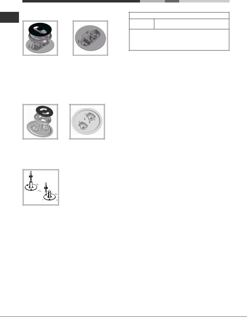
GB 3. Replace all the components by repeating the steps in reverse order.
Replacing the Triple ring burner nozzles
1.Remove the pan supports and lift the burners out of their housing. The burner consists of two separate parts (see pictures).
2.Unscrew the nozzles using a 7 mm socket spanner. Replace the nozzles withmodelsthatareconfiguredforusewiththenewtypeofgas(seeTable
1). The two nozzles have the same hole diameter.
3.Replace all the components by completing the above operations in reverse order.
•Adjusting the burners’ primary air Does not require adjusting.
•Setting the burners to minimum
1.Turn the tap to the low flame position;
2.Removetheknobandadjusttheadjustment
screw, which is positioned in or next to the tap pin, until the flame is small but steady.
3.Having adjusted the flame to the required low setting, while the burner is alight, quickly change the position of the knob from minimum to maximum and vice versa several times, checking that the flame does not go out.
4.Someapplianceshaveasafetydevice(thermocouple)fitted.Ifthedevice fails to work when the burners are set to the low flame setting, increase this low flame setting using the adjusting screw.
5.Once the adjustment has been made, replace the seals on the by-passes using sealing wax or a similar substance.
!If the appliance is connected to liquid gas, the regulation screw must be fastened as tightly as possible.
!Once this procedure is finished, replace the old rating sticker with one indicating the new type of gas used. Stickers are available from any of our Service Centres.
!Should the gas pressure used be different (or vary slightly) from the recommended pressure, a suitable pressure regulator must be fitted to the inlet pipe (in order to comply with current national regulations).
DATA PLATE
Electrical |
see data plate |
connections |
ECODESIGN
This appliance conforms to the EU Regulation no. 66/2014 implementing Directive 2009/125/EC.
standard EN 30-2-1
10
|
|
|
|
|
|
|
|
|
|
|
|
|
|
|
|
|
|
|
|
|
|
|
|
|
|
|
|
|
|
|
|
|
|
|
|
|
|
|
|
Burner and nozzle specifications |
|
|
|
|
|
|
|
|
|
|
|
|
|
|
|
||||
|
|
|
|
|
|
|
|
|
|
|
|
|
|
GB |
|||||
|
|
|
|
|
|
|
|
|
|
|
|
|
|
|
|
|
|
|
|
Table 1 |
|
|
|
|
|
Liquid Gas |
|
|
|
|
|
Natural Gas |
|
|
|
||||
|
|
|
|
|
|
|
|
|
|
|
|
|
|||||||
|
|
|
|
|
|
|
|
|
|
|
|
|
|
|
|
|
|||
Burner |
Diameter |
Thermal |
Thermal |
|
By-pass |
Nozzle |
|
Flow* |
|
Thermal |
|
Nozzle |
|
Flow* |
|
||||
|
|
power |
power |
|
1/100 |
1/100 |
|
(g/h) |
|
|
power |
|
1/100 |
|
(l/h) |
|
|||
|
|
kW |
kW |
|
(mm) |
|
|
|
|
|
|
|
|
kW |
|
|
|
|
|
|
|
(p.c.s.*) |
(p.c.s.*) |
|
|
|
|
|
|
|
|
|
|
(p.c.s.*) |
|
|
|
|
|
|
(mm) |
Reduced |
Nominal |
|
|
(mm) |
|
*** |
|
** |
Nominal |
|
(mm) |
|
|
|
|
||
|
|
|
|
|
|
|
|
|
|
|
|
|
|
|
|
|
|
||
Reduced Fast (RR) |
100 |
0.70 |
2.60 |
|
39 |
80 |
|
189 |
|
186 |
2.60 |
|
122(H3) |
|
248 |
|
|
||
|
|
|
|
|
|
|
|
|
|
|
|
|
|
|
|
|
|
||
Semi Fast (S) |
75 |
0.40 |
1.65 |
|
28 |
64 |
|
120 |
|
118 |
1.65 |
|
96(Z) |
|
157 |
|
|
||
|
|
|
|
|
|
|
|
|
|
|
|
|
|
|
|
|
|
||
Auxiliary (A) |
55 |
0.40 |
1.00 |
|
28 |
50 |
|
73 |
|
71 |
1.00 |
|
79(6) |
|
95 |
|
|
||
|
|
|
|
|
|
|
|
|
|
|
|
|
|
|
|
|
|
||
Triple Crown (TC) |
130 |
1.50 |
3.30 |
|
61 |
65x2 |
|
240 |
|
236 |
3.60 |
|
103x2 |
|
343 |
|
|
||
|
|
|
|
|
|
|
|
|
|
|
|
|
|
|
|
|
|
|
|
Double Flame |
36 |
0.40 |
0.90 |
|
28 |
44 |
|
65 |
|
64 |
0.90 |
|
74 |
|
|
86 |
|
|
|
(DCDR Internal) |
|
|
|
|
|
|
|
|
|
|
|
|
|
|
|
|
|
|
|
|
|
|
|
|
|
|
|
|
|
|
|
|
|
|
|
|
|
|
|
Double Flame |
130 |
1.50 |
4.10 |
|
61 |
70x2 |
|
298 |
|
293 |
4.10 |
|
110x2 |
|
390 |
|
|
||
(DCDR External) |
|
|
|
|
|
|
|
||||||||||||
2 nozzle |
|
|
|
|
|
|
|
|
|
|
|
|
|
|
|
|
|
|
|
Supply pressures |
|
Nominal (mbar) |
|
|
|
28-30 |
|
37 |
|
|
20 |
|
|
|
|
|
|||
|
|
Minimum (mbar) |
|
|
|
20 |
|
25 |
|
|
17 |
|
|
|
|
|
|||
|
|
Maximum (mbar) |
|
|
35 |
|
45 |
|
|
25 |
|
|
|
|
|
||||
|
|
|
|
|
|
|
|
|
|
|
|
|
|
|
|
|
|
|
|
*At 15°C and 1013,25 mbar - dry gas
**Propane P.C.S. = 50.37 MJ/Kg
***Butane P.C.S. = 49.47 MJ/Kg Natural P.C.S. = 37.78 MJ/m³
A |
|
|
|
S |
|
|
RR |
TC |
|
|
|
||
DC |
TC |
DC |
TC |
|||
|
|
|||||
S |
|
|
|
|
|
|
PCN 642 T/IX/A |
|
PNC 722 T/D2/IX/AX |
|
PCN 732 T/D2/IX/A |
|
11

GB Start-up and use
! The position of the corresponding gas burner is shown on every knob.
Gas burners
Each burner can be adjusted to one of the following settings using the corresponding control knob:
●Off
Maximum
Minimum
To light one of the burners, hold a lit match or lighter near the burner and, at the same time, press down and turn the corresponding knob anti-clockwise to the maximum setting.
Since the burner is fitted with a safety device, the knob should be pressed for approximately 2-3 seconds to allow the automatic device keeping the flame alight to heat up.
When using models with an ignition button, light the desired burner pressing down the corresponding knob as far as possible and turning it anticlockwise towards the maximum setting.
! Ifaflameisaccidentallyextinguished,turnoffthecontrolknobandwaitfor at least 1 minute before trying to relight it.
To switch off the burner, turn the knob in a clockwise direction until it stops
(when reaches the “●” position).
The “separate double flame” burner*
This burner consists of two concentric burners which can operate either together or separately.
Use of the double flame on the maximum setting gives a very high power which reduces cooking times with respect to conventional burners.
Moreoverthedoubleflamecrownprovidesamoreuniformdistributionofheat on the bottom of the pan, when using both burners on minimum.
To ensure that the double-flame burner is used to its full potential, never set the inside ring to minimum and the outside ring to maximum at the same time.
Pots and pans of all sizes can be used. In the case of the smaller pots and pans we recommend the use of only the internal burner.
There is a separate control knob for each of the “separate double flame”
burners. |
|
|
The knob marked by the symbol |
|
operates the external burner; |
The knob marked by the symbol |
|
operates the internal burner. |
|
To turn on one of the rings, press the relative knob in all the way and turn it
anti-clockwise to the high setting  .
.
The burner is fitted with an electronic igniter that automatically starts when the knob is pressed in.
Since the burner is equipped with a safety device, after lighting the burner keep the knob pressed in for about 2-3 seconds to allow the device which keeps the flame lit automatically to heat up.
The selected burner can be regulated using the corresponding knob, as follows:
●Off
Maximum
Minimum
*Only available on certain models.
To switch off the burner, turn the knob in a clockwise direction until it stops
(when reaches the “●” position).
Practical advice on using the burners
To ensure the burners operate efficiently:
•Use appropriate cookware for each burner(see table) so that the flames do not extend beyond the bottom of the cookware.
•Always use cookware with a flat base and a cover.
•When the contents of the pan reach boiling point, turn the knob to minimum.
Burner |
|
Ø Cookware diameter (cm) |
Reduced Rapid (RR) |
|
24 - 26 |
|
|
|
Semi Rapid (S) |
|
16 - 20 |
|
|
|
Auxiliary (A) |
|
10 - 14 |
|
|
|
Triple Crown (TC) |
|
24 - 26 |
Pans to be used on 60 cm hobs |
|
|
Burner |
Ø Cookware diameter (cm) |
|
|
Semi Rapid (S) |
16 - 20 |
|
|
Triple Crown (TC) |
24 - 26 |
|
|
Double Flame (DCDR internal) |
10 - 14 |
|
|
Double Flame (DCDR external) |
26 - 28 |
|
|
Pans to be used on 75 cm hobs |
|
! On the models supplied with a reducer shelf, remember that this should be usedonlyfortheDoubleflameinternal(DCDRinternal)burnerwhenyouuse casserole dishes with a diameter under 12 cm.
To identify the type of burner, refer to the designs in the section entitled, “Burner and Nozzle Specifications”.
•For maximum stability, always make sure that the pan supports are correctly fitted and that each pan is placed centrally over the burner.
•Pan handles should be positioned in line with one of the support bars on the pan support grid.
•Pan handle should be positioned so not to protrude beyond the front edge of the hob.
The more variable aspect in terms of pan stability can often be the pan itself, (or the positioning of that pan during use).
Well balanced pans, with flat bases that
are placed centrally over the burner, with the pan handles aligned with one of the support fingers obviously offer the
greatest stability.
Precautions and tips
! This appliance has been designed and manufactured in compliance with international safety standards. The following warnings are provided for safety reasons and must be read carefully.
General safety
•This is a class 3 built-in appliance.
•Gas appliances require regular air exchange to maintain efficient operation.Wheninstallingthehob,followtheinstructionsprovided in the paragraph on “Positioning” the appliance.
•These instructions are only valid for the countries whose symbols appear in the manual and on the serial number plate.
•The appliance was designed for domestic use inside the home and is not intended for commercial or industrial use.
12

•The appliance must not be installed outdoors, even in covered areas. It is extremely dangerous to leave the appliance exposed to rain and storms.
•Do not touch the appliance with bare feet or with wet or damp hands and feet.
•Theappliancemustbeusedbyadultsonlyforthepreparationoffood, inaccordancewiththeinstructionsoutlinedinthisbooklet.Anyother use of the appliance (e.g. for heating the room) constitutes improper use and is dangerous. The manufacturer may not be held liable for any damage resulting from improper, incorrect and unreasonable use of the appliance.
•The openings used for ventilation and dispersion of heat must never be covered.
•Alwaysmakesuretheknobsareinthe“●”/“○” position when the appliance is not in use.
•When unplugging the appliance always pull the plug from the mains socket, do not pull on the cable.
•Nevercarryoutanycleaningormaintenanceworkwithouthavingdetached the plug from the mains.
•Incaseofmalfunction,undernocircumstancesshouldyouattempttorepair the appliance yourself. Repairs carried out by inexperienced persons may cause injury or further malfunctioning of the appliance. Contact a Service Centre (see Assistance).
•Do not close the glass cover (if present) when the gas burners or electric hotplates are still hot.
•The appliance should not be operated by people (including children) with reduced physical, sensory or mental capacities, by inexperienced individuals or by anyone who is not familiar with the product. These individuals should, at the very least, be supervised by someone who assumes responsibility for their safety or receive preliminary instructions relating to the operation of the appliance.
•Do not let children play with the appliance.
•The appliance is not intended to be operated by means of an external timer or separate remote-control system.
Disposal
•When disposing of packaging material: observe local legislation so that the packaging may be reused.
•The European Directive 2012/19/EU on Waste Electrical and Electronic Equipment(WEEE),requiresthatoldhouseholdelectricalappliancesmust not be disposed of in the normal unsorted municipal waste stream. Old appliances must be collected separately in order to optimise the recovery and recycling of the materials they contain and reduce the impact on human health and the environment.The crossed out “wheeled bin” symbol on the product reminds you of your obligation, that when you dispose of the appliance it must be separately collected.
Consumers should contact their local authority or retailer for information concerning the correct disposal of their old appliance.
Respecting and conserving the environment
•Cookyourfoodinclosedpotsorpanswithwell-fittinglidsanduseaslittle water as possible. Cooking with the lid off will greatly increase energy consumption.
•Use purely flat pots and pans.
•If you are cooking something that takes a long time, it’s worth using a pressure cooker, which is twice as fast and saves a third of the energy.
Maintenance and care |
|
GB |
|
||
|
|
Switching the appliance off
Disconnect your appliance from the electricity supply before carrying out any work on it.
Cleaning the hob surface
•All the enamelled and glass parts should be cleaned with warm water and neutral solution.
•Stainless steel surfaces may be stained by calcareous water or aggressive detergents if left in contact for too long.Any food spills (water, sauce, coffee, etc.) should be wiped away before they dry.
•Clean with warm water and neutral detergent, and then dry with a soft clothorchamois.Removebaked-ondirtwithspecificcleanersforstainless steel surfaces.
•Clean stainless steel only with soft cloth or sponge.
•Do not use abrasive or corrosive products, chlorine-based cleaners or pan scourers.
•Do not use steam cleaning appliances.
•Do not use flammable products.
•Do not leave acid or alkaline substances, such as vinegar, mustard, salt, sugar or lemon juice on the hob.
Cleaning the hob parts
•Clean the enamelled and glass parts only with soft cloth or sponge.
•Grids, burner caps and burners can be removed to be cleaned.
•Clean them by hand with warm water and non-abrasive detergent, removing any food residues and checking that none of the burner openings is clogged.
•Rinse and dry.
•Refit burners and burner caps correctly in the respective housings.
•When replacing the grids, make sure that the panstand area is aligned with the burner.
•Models equipped with electrical ignition plugs and safety device require thorough cleaning of the plug end in order to ensure correct operation. Check these items frequently, and if necessary, clean them with a damp cloth. Any baked-on food should be removed with a toothpick or needle.
! Toavoiddamagingtheelectricignitiondevice,donotuseitwhenthe burners are not in their housing.
Gas tap maintenance
Over time, the taps may become jammed or difficult to turn. If this happens, the tap must be replaced.
!Thisproceduremustbeperformedbyaqualifiedtechnicianauthorised by the manufacturer.
Troubleshooting
It may happen that the appliance does not function properly or at all. Before calling the service centre for assistance, check if anything can be done. First, check to see that there are no interruptions in the gas and electrical supplies, and, in particular, that the gas valves for the mains are open.
13
 Loading...