


WPS1200 WasteProTM
WASTE EQUIPMENT SYSTEM
MODEL
WPS1200 ML-130046
701 S. RIDGE AVENUE TROY, OHIO 45374-0001
937 332-3000
www.hobartcorp.com |
FORM 35393 (Oct 2014) |
|

TABLE OF CONTENTS
GENERAL . . . . . . . . . . . . . . . . . . . . . . . . . . . . . . . . . . . . . . . . . . . . . . . . . . . . . . . . . . . . . . . . . . . . . . . . . . |
3 |
INSTALLATION . . . . . . . . . . . . . . . . . . . . . . . . . . . . . . . . . . . . . . . . . . . . . . . . . . . . . . . . . . . . . . . . . . . . . . . . . 4 UNPACKING . . . . . . . . . . . . . . . . . . . . . . . . . . . . . . . . . . . . . . . . . . . . . . . . . . . . . . . . . . . . . . . . . . . . . . . 4 LOCATION . . . . . . . . . . . . . . . . . . . . . . . . . . . . . . . . . . . . . . . . . . . . . . . . . . . . . . . . . . . . . . . . . . . . . . . . . 4 VIBRATION ISOLATION FOOTPADS AND LEVELING . . . . . . . . . . . . . . . . . . . . . . . . . . . . . . . . . . . . 4 CHEMICAL FEEDER PUMP . . . . . . . . . . . . . . . . . . . . . . . . . . . . . . . . . . . . . . . . . . . . . . . . . . . . . . . . . . 4 THE FOLLOWING PARTS MAY BE INCLUDED (DEPENDING ON OPTIONS SELECTED) . . . . . 4 SILVER SAVER — BY OTHERS (TROUGH EQUIPPED UNITS ONLY) . . . . . . . . . . . . . . . . . . . . . . 5 TROUGH GASKET (TROUGH EQUIPPED UNITS ONLY) . . . . . . . . . . . . . . . . . . . . . . . . . . . . . . . . . . 5 OPTIONAL MAGNET FOR SILVER SAVER (TROUGH EQUIPPED UNITS ONLY). . . . . . . . . . . . . 5 TROUGH PIPING DETAIL (TROUGH EQUIPPED UNITS ONLY) . . . . . . . . . . . . . . . . . . . . . . . . . . . . 6 FLANGE DETAIL . . . . . . . . . . . . . . . . . . . . . . . . . . . . . . . . . . . . . . . . . . . . . . . . . . . . . . . . . . . . . . . . . . . 6 PULPER INSTALLED UNDER A DISH TABLE . . . . . . . . . . . . . . . . . . . . . . . . . . . . . . . . . . . . . . . . . . . 7 PLUMBING CONNECTIONS . . . . . . . . . . . . . . . . . . . . . . . . . . . . . . . . . . . . . . . . . . . . . . . . . . . . . . . . . . 8
WATER CONNECTION . . . . . . . . . . . . . . . . . . . . . . . . . . . . . . . . . . . . . . . . . . . . . . . . . . . . . . . . . . 8 DRAIN CONNECTION . . . . . . . . . . . . . . . . . . . . . . . . . . . . . . . . . . . . . . . . . . . . . . . . . . . . . . . . . . . 8 ELECTRICAL CONNECTIONS . . . . . . . . . . . . . . . . . . . . . . . . . . . . . . . . . . . . . . . . . . . . . . . . . . . . . . . . 8 REMOTE PUSH-BUTTON STATION . . . . . . . . . . . . . . . . . . . . . . . . . . . . . . . . . . . . . . . . . . . . . . . 9 MOTOR ROTATION . . . . . . . . . . . . . . . . . . . . . . . . . . . . . . . . . . . . . . . . . . . . . . . . . . . . . . . . . . . . . 9 ELECTRICAL INSTALLATION . . . . . . . . . . . . . . . . . . . . . . . . . . . . . . . . . . . . . . . . . . . . . . . . . . . . 9 ELECTRICAL INSTALLATION DIAGRAM . . . . . . . . . . . . . . . . . . . . . . . . . . . . . . . . . . . . . . . . . . 10
OPERATION . . . . . . . . . . . . . . . . . . . . . . . . . . . . . . . . . . . . . . . . . . . . . . . . . . . . . . . . . . . . . . . . . . . . . . . . . 11 CONTROLS . . . . . . . . . . . . . . . . . . . . . . . . . . . . . . . . . . . . . . . . . . . . . . . . . . . . . . . . . . . . . . . . . . . . . . . 11 FEEDING INSTRUCTIONS . . . . . . . . . . . . . . . . . . . . . . . . . . . . . . . . . . . . . . . . . . . . . . . . . . . . . . . . . . 12 SHUTDOWN PROCEDURE . . . . . . . . . . . . . . . . . . . . . . . . . . . . . . . . . . . . . . . . . . . . . . . . . . . . . . . . . . 13 CLEANING . . . . . . . . . . . . . . . . . . . . . . . . . . . . . . . . . . . . . . . . . . . . . . . . . . . . . . . . . . . . . . . . . . . . . . . . 13
CLEANING INSTRUCTIONS . . . . . . . . . . . . . . . . . . . . . . . . . . . . . . . . . . . . . . . . . . . . . . . . . . . . . 13 CLEANING COMPOUNDS . . . . . . . . . . . . . . . . . . . . . . . . . . . . . . . . . . . . . . . . . . . . . . . . . . . . . . . 13
MAINTENANCE . . . . . . . . . . . . . . . . . . . . . . . . . . . . . . . . . . . . . . . . . . . . . . . . . . . . . . . . . . . . . . . . . . . . . . . . 14 MOTORS . . . . . . . . . . . . . . . . . . . . . . . . . . . . . . . . . . . . . . . . . . . . . . . . . . . . . . . . . . . . . . . . . . . . . . . . . 14 WATERPRESS DRIVE . . . . . . . . . . . . . . . . . . . . . . . . . . . . . . . . . . . . . . . . . . . . . . . . . . . . . . . . . . . . . . 14
TROUBLESHOOTING . . . . . . . . . . . . . . . . . . . . . . . . . . . . . . . . . . . . . . . . . . . . . . . . . . . . . . . . . . . . . . . . . . . 15
SERVICE . . . . . . . . . . . . . . . . . . . . . . . . . . . . . . . . . . . . . . . . . . . . . . . . . . . . . . . . . . . . . . . . . . 16
© HOBART, 2005 |
– 2 – |
|
Installation, Operation and Care of
WPS1200 WasteProTM
WASTE EQUIPMENT SYSTEM
SAVE THESE INSTRUCTIONS
GENERAL
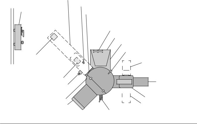
The WPS1200 Waste Equipment System prepares waste materials for disposal using a self-contained pulper and a waterpress. Paper, plastic, foil and food waste are fed into the pulper, shredded into small pieces in water to make a slurry. The waterpress lifts the slurry using a stainless steel screw inside of a perforated tubular screen. The water passes through the screen and is pumped back to the pulper. The solids continue up the screw where they are further compacted to a semi-dry pulp, exiting through the discharge chute to a waste container. Fresh make-up water is supplied to the pulper automatically through a solenoid valve. The original volume of waste material is reduced significantly.
The pulper has a 6 h.p. motor, stainless steel components, carbide and hardened stainless steel shredder blades. The 2 h.p. motor at the waterpress turns the stainless steel screw. A 3 h.p. motor and pump returns the process water to the pulper.
An optional feed tray (by Hobart) allows waste materials to be fed into the pulper. A feed trough (fabricated by tabling suppliers) allows waste materials and water to feed through an optional watertight opening into the pulper. A flush nozzle with throttling valve (by Hobart) is an available option for the front end of the trough. A silver-saver sink (by others) can be installed in the feed trough; a silver saver magnet is an available option (by Hobart). Mounted below the sink, it restrains ferro-magnetic objects from entering into the pulper.
FEED TROUGH (BY OTHERS)
1 X 1" PIPE — DRAIN FLUSH
WALL-MOUNTED
CONTROL BOX
FEED TROUGH CONNECTION
(ALTERNATE POSITIONS
AT 15° ANGLES)
MACHINE CONTROL BOX
FLUSH NOZZLE
SILVER SAVER SINK (BY OTHERS)
MAGNET
REMOTE PUSHBUTTON STATION
PULPER
FEED TRAY (ALTERNATE
POSITIONS AT 15° ANGLES)
WATER SUPPLY CONNECTIONS
PULPER MOTOR HOUSING
HINGED COVER / LID LATCH (OPPOSITE
FEED TROUGH OR FEED TRAY)
DISCHARGE CHUTE (ALTERNATE POSITION)


 CHEMICAL FEEDER PUMP
DISCHARGE CHUTE

 WATERPRESS MOTOR
WATERPRESS
DISCHARGE CHUTE
(ALTERNATE POSITION)
DRAIN VALVE
Fig. 1
– 3 –

INSTALLATION
Prior to installation, test the electrical service to assure that it agrees with the specifications on the machine data plate located on the front of the pulper.
UNPACKING
Immediately after unpacking, check for possible shipping damage. If the unit is found to be damaged, save the packaging material and contact the carrier within 15 days of delivery.
LOCATION
Locate the waste system near a floor drain; floor should be pitched a minimum of 1/4" per foot to the floor drain. A suitable amount of space should be provided for machine operation, cleaning and service.
VIBRATION ISOLATION FOOTPADS AND LEVELING
Vibration isolation footpads (standard — Fig. 2) must be installed on each of the six legs of the waste system before making connections. Level the units by threading the adjustable feet up or down as necessary.
CHEMICAL FEEDER PUMP (STANDARD)
LEG |
|
|
RUBBER |
|
ADJUSTABLE |
|
|
||
|
|
FOOTPAD |
||
FOOT |
|
|
||
|
|
|
||
|
|
|
|
|
|
|
|
|
|
|
|
|
|
|
|
|
|
|
|
Fig. 2
The chemical feeder pump is mounted on the waterpress. It has its own on-off switch. When on, the chemical feeder pumps a chemical additive into the waterpress to control odors, to buffer the acidity of the system water and to reduce foaming. Contact your chemical supplier for a recommendation for the appropriate chemical additive. The recommended chemical pump setting is #1 which delivers 0.3 gallons per day. Each subsequent setting number is a direct multiple of setting #1. For example, setting #2 delivers 0.6 gallons per day, etc.
Two pieces of polyethylene tubing with pre-assembled tubing fittings, provided with the system, must be connected to the chemical feeder pump during installation. Tubing fittings must be properly tightened but not over-tightened. Connect the short piece to the output line on the chemical feeder pump and to the terminal on top of waterpress. Connect the long piece to the chemical feeder supply line and insert the other end into a one gallon container of chemical additive.
THE FOLLOWING PARTS MAY BE INCLUDED (DEPENDING ON OPTIONS SELECTED)
2 |
11/2" Brass Valves: for feed tray flush (option) and for the feed trough flush (option). |
1 |
Nozzle for trough flush, rectangular piece has pipe thread with locknut on back. |
1 |
Magnet (option) for silver saver sink. |
6 |
Black Rubber Vibration Isolators for the legs; and a package of |
6 |
Stainless steel screws (10-32 x 11/2") with nuts, washers and lockwashers. |
1 |
Black Rubber Gasket with slit curtain for trough opening; which also includes approximately |
16 |
Stainless steel screws (10-32 x 1/2") with nuts, washers and lockwashers. |
1 |
Push-button Station with Start, Stop and Timed Stop switches (second p/b station is an option). |
1 |
Remote Control Box (for wall mounting). |
1 |
1/2" SST Nipple for Silver Saver Flush |
– 4 –

SILVER SAVER — BY OTHERS (TROUGH EQUIPPED UNITS ONLY)
Connect plumbing, not provided, from the stainless steel pipe nipple (1" I.D. x 1" long, not provided) to a drain. Include a shut-off valve.
TROUGH GASKET (TROUGH EQUIPPED UNITS ONLY)
Install the trough gasket between the pulper's Trough Flange and the trough's outlet. Drill a hole pattern in the pulper's Trough Opening flange to match the holes in the hole pattern in the trough outlet flange; secure with the provided hardware.
OPTIONAL MAGNET FOR SILVER SAVER (TROUGH EQUIPPED UNITS ONLY)
Install the magnet underneath the silver saver by tack welding to the under side. Alternatively, drill four 7/32" diameter holes in the silver saver, and secure the magnet with the hardware, provided; seal the heads of the screws with silicone sealant. Refer to Fig. 3 for position of the magnet; refer to Fig. 4 for mounting detail.
Fig. 3
MAGNET MOUNT DETAIL
Fig. 4
– 5 –
 Loading...