

Page 1
TNC 640
User’s Manual
Cycle Programming
NC Software
340590-05
340591-05
340595-05
English (en)
1/2015
Page 2

Page 3

Fundamentals
Page 4
Fundamentals
About this Manual
About this Manual
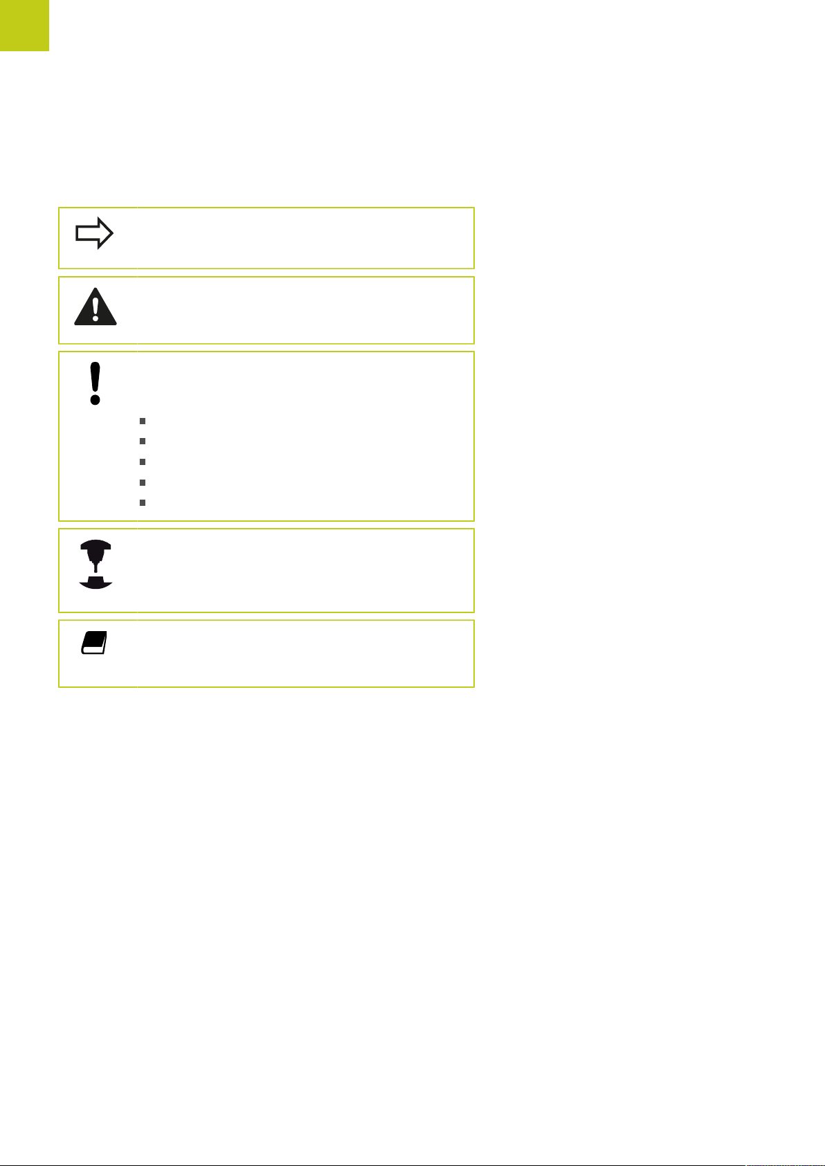
The symbols used in this manual are described below.
This symbol indicates that important information
about the function described must be considered.
WARNING This symbol indicates a possibly
dangerous situation that may cause light injuries if
not avoided.
This symbol indicates that there is one or more
of the following risks when using the described
function:
Danger to workpiece
Danger to fixtures
Danger to tool
Danger to machine
Danger to operator
This symbol indicates that the described function
must be adapted by the machine tool builder. The
function described may therefore vary depending on
the machine.
This symbol indicates that you can find detailed
information about a function in another manual.
Would you like any changes, or have you found any errors?
We are continuously striving to improve our documentation for you.
Please help us by sending your requests to the following e-mail
address: tnc-userdoc@heidenhain.de.
4
TNC 640 | User's Manual Cycle Programming | 1/2015
Page 5

TNC model, software and features
TNC model, software and features
This manual describes functions and features provided by TNCs as
of the following NC software numbers.
TNC model NC software number
TNC 640 340590-05
TNC 640 E 340591-05
TNC 640 Programming Station 340595-05
The suffix E indicates the export version of the TNC. The export
version of the TNC has the following limitations:
Simultaneous linear movement in up to 4 axes
The machine tool builder adapts the usable features of the TNC to
his machine by setting machine parameters. Some of the functions
described in this manual may therefore not be among the features
provided by the TNC on your machine tool.
TNC functions that may not be available on your machine include:
Tool measurement with the TT
Please contact your machine tool builder to become familiar with
the features of your machine.
Many machine manufacturers, as well as HEIDENHAIN, offer
programming courses for the TNCs. We recommend these courses
as an effective way of improving your programming skill and
sharing information and ideas with other TNC users.
User's Manual:
All TNC functions that have no connection with
cycles are described in the User's Manual of the TNC
640. Please contact HEIDENHAIN if you require a
copy of this User's Manual.
ID of User's Manual for conversational programming:
892904-xx.
ID of User’s Manual for DIN/ISO programming:
892910-xx.
TNC 640 | User's Manual Cycle Programming | 1/2015
5
Page 6

Fundamentals
TNC model, software and features
Software options
The TNC 640 features various software options that can be enabled by your machine tool builder. Each option is to
be enabled separately and contains the following respective functions:
Additional Axis (option number 0 to option number 7)
Additional axis
Advanced Function Set 1 (option 8)
Expanded functions Group 1 Machining with rotary tables
Advanced Function Set 2 (option 9)
Expanded functions Group 2 3-D machining:
Additional control loops 1 to 8
Cylindrical contours as if in two axes
Feed rate in distance per minute
Coordinate transformations:
Tilting the working plane
Interpolation:
Circle in 3 axes with tilted working plane (spatial arc)
Motion control with minimum jerk
3-D tool compensation through surface normal vectors
Using the electronic handwheel to change the angle of the swivel
head during program run without affecting the position of the tool
point. (TCPM = Tool Center Point Management)
Keeping the tool normal to the contour
Tool radius compensation perpendicular to traversing direction and
tool direction
Interpolation:
Linear in 5 axes (subject to export permit)
Touch Probe Functions (option 17)
Touch probe functions
HEIDENHAIN DNC (option number 18)
Display Step (Option #23)
Display step Input resolution:
Touch probe cycles:
Compensation of tool misalignment in automatic mode
Datum setting in the Manual Operation mode
Datum setting in automatic mode
Automatically measuring workpieces
Tools can be measured automatically
Communication with external PC applications over COM component
Linear axes down to 0.01 µm
Rotary axes to 0.00001°
6
TNC 640 | User's Manual Cycle Programming | 1/2015
Page 7

Dynamic Collision Monitoring – DCM (Option #40)
TNC model, software and features
Dynamic Collision Monitoring
DXF Converter (Option #42)
DXF converter
Adaptive Feed Control – AFC (Option #45)
Adaptive Feed Control
KinematicsOpt (Option #48)
Optimizing the machine
kinematics
The machine manufacturer defines objects to be monitored
Warning in Manual operation
Program interrupt in Automatic operation
Includes monitoring of 5-axis movements
Supported DXF format: AC1009 (AutoCAD R12)
Adoption of contours and point patterns
Simple and convenient specification of reference points
Select graphical features of contour sections from conversational
programs
Recording the actual spindle power by means of a teach-in cut
Defining the limits of automatic feed rate control
Fully automatic feed control during program run
Backup/restore active kinematics
Test active kinematics
Optimize active kinematics
Mill-Turning (Option #50)
Milling and turning modes Functions:
Switching between Milling/Turning mode of operation
Constant surface speed
Tool-tip radius compensation
Turning cycles
Extended Tool Management (Option #93)
Extended tool management Python-based
Spindle Synchronism (Option #131)
Spindle synchronization Synchronization of milling spindle and turning spindle
Remote Desktop Manager (Option #133)
Remote operation of external
computer units
Synchronizing Functions (Option #135)
Synchronization functions Real Time Coupling – RTC:
Windows on a separate computer unit
Incorporated in the TNC interface
Coupling of axes
TNC 640 | User's Manual Cycle Programming | 1/2015
7
Page 8

Fundamentals
Cross Talk Compensation – CTC (Option #141)
TNC model, software and features
Compensation of axis couplings
Position Adaptive Control – PAC (Option #142)
Adaptive position control
Load Adaptive Control – LAC (Option #143)
Adaptive load control
Active Chatter Control – ACC (Option #145)
Active chatter control Fully automatic function for chatter control during machining
Determination of dynamically caused position deviation through axis
acceleration
Compensation of TCP (Tool Center Point)
Changing of the control parameters depending on the position of
the axes in the working space
Changing of the control parameters depending on the speed or
acceleration of an axis
Automatic determination of workpiece weight and frictional forces
Changing of control parameters depending on the actual mass of
the workpiece
8
TNC 640 | User's Manual Cycle Programming | 1/2015
Page 9

TNC model, software and features
Feature Content Level (upgrade functions)
Along with software options, significant further improvements
of the TNC software are managed via the Feature Content Level
upgrade functions. Functions subject to the FCL are not available
simply by updating the software on your TNC.
All upgrade functions are available to you without
surcharge when you receive a new machine.
Upgrade functions are identified in the manual with FCL n, where n
indicates the sequential number of the feature content level.
You can purchase a code number in order to permanently enable
the FCL functions. For more information, contact your machine tool
builder or HEIDENHAIN.
Intended place of operation
The TNC complies with the limits for a Class A device in
accordance with the specifications in EN 55022, and is intended for
use primarily in industrially-zoned areas.
Legal information
This product uses open source software. Further information is
available on the control under
Programming and Editing operating mode
MOD function
LICENSE INFO softkey
TNC 640 | User's Manual Cycle Programming | 1/2015
9
Page 10

Fundamentals
Optional parameters
Optional parameters
The comprehensive cycle package is continuously further
developed by HEIDENHAIN. Every new software version thus
may also introduce new Q parameters for cycles. These new Q
parameters are optional parameters, some of which have not been
available in previous software versions. Within a cycle, they are
always provided at the end of the cycle definition. You will find an
overview of the optional Q parameters that have been added with
this software version in the "New and changed cycle functions of
software 34059x-05" section. You can choose whether to define
optional parameters or delete them with the NO ENT key. You can
also adopt the default value. If you have accidentally deleted an
optional Q parameter or if you would like to extend cycles in your
existing programs after a software update, you can include optional
Q parameters in cycles when needed. The following steps describe
how this is done:
To insert optional Q parameters in existing programs:
Call the cycle definition
Press the right arrow key until the new Q parameters are
displayed
Apply the default value or enter a value
To transfer the new Q parameter, exit the menu by pressing
the right arrow key once again or by pressing END
If you do not wish to apply the new Q parameter, press the
NO ENT key
Compatibility
The majority of part programs created on older HEIDENHAIN
contouring controls (TNC 150 B and higher) can be executed with
this new software version of the TNC 640. Even if new, optional
parameters ("Optional parameters") have been added to existing
cycles, you can normally continue running your programs as usual.
This is achieved by using the stored default value. The other way
round, if a program created with a new software version is to be
run on an older control, you can delete the respective optional
Q parameters from the cycle definition with the NO ENT key.
In this way you can ensure that the program will be downward
compatible. If NC blocks contain invalid elements, the TNC will
mark them as ERROR blocks when the file is opened.
10
TNC 640 | User's Manual Cycle Programming | 1/2015
Page 11

New cycle functions of software 34059x-04
New cycle functions of software 34059x-04
The character set of the fixed cycle 225 Engraving was
expanded by more characters and the diameter sign see
"ENGRAVING (Cycle 225, DIN/ISO: G225)", page 300
New fixed cycle 275 Trochoidal Milling see "TROCHOIDAL SLOT
(Cycle 275, DIN ISO G275)", page 211
New fixed cycle 233 Face Milling see "FACE MILLING (Cycle
233, DIN/ISO: G233)", page 167
In Cycle 205 Universal Pecking you can now use parameter
Q208 to define a feed rate for retraction see "Cycle parameters",
page 92
In the thread milling cycles 26x an approaching feed rate was
introduced see "Cycle parameters", page 119
The parameter Q305 NUMBER IN TABLE was added to Cycle
404 see "Cycle parameters", page 462
In the drilling cycles 200, 203 and 205 the parameter Q395
DEPTH REFERENCE was introduced in order to evaluate the T
ANGLE see "Cycle parameters", page 92
Cycle 241 SINGLE-LIP DEEP HOLE DRILLING was expanded
by several input parameters see "SINGLE-LIP DEEP-HOLE
DRILLING (Cycle 241, DIN/ISO: G241)", page 97
The probing cycle 4 MEASURING IN 3-D was introduced see
"MEASURING IN 3-D (Cycle 4)", page 567
TNC 640 | User's Manual Cycle Programming | 1/2015
11
Page 12

Fundamentals
New and changed cycle functions of software 34059x-05
New and changed cycle functions of
software 34059x-05
New Cycle 880 GEAR HOBBING (software option 50), see
"GEAR HOBBING (Cycle 880, DIN/ISO: G880)", page 425
New Cycle 292 CONTOUR TURNING INTERPOLATION
(software option 96), see "CONTOUR TURNING
INTERPOLATION (Cycle 292, DIN/ISO: G292, software option
96)", page 286
New Cycle 291 COUPLING TURNING INTERPOLATION
(software option 96), see "COUPLING TURNING
INTERPOLATION (Cycle 291, DIN/ISO: G291, software option
96)", page 295
New Load Adaptive Control (LAC) cycle for the load-dependent
adaptation of control parameters (software option 143), see
"ASCERTAIN THE LOAD (Cycle 239, DIN/ISO: G239, software
option 143)", page 309
Cycle 270: CONTOUR TRAIN DATA was added to the cycle
package (software option 19), see "CONTOUR TRAIN DATA
(Cycle 270, DIN/ISO: G270)", page 210
Cycle 39 CYLINDER SURFACE (software option 1) Contour was
added to the cycle package, see "CYLINDER SURFACE (Cycle
39, DIN/ISO: G139, software option 1)", page 232
The character set of the fixed cycle 225 Engraving was
expanded by the CE, ß and @ characters and the system time,
see "ENGRAVING (Cycle 225, DIN/ISO: G225)", page 300
Cycles 252 to 254 were expanded by the optional parameter
Q439, see "Cycle parameters", page 148
Cycle 22 was expanded by the optional parameters Q401 and
Q404, see "ROUGHING (Cycle 22, DIN/ISO: G122)", page 199
Cycles 841, 842, 851 and 852 were expanded by the plunging
feed rate Q488, see "Cycle parameters", page 372
Cycle 484 was expanded by the optional parameter Q536, see
"Calibrate the wireless TT 449 (Cycle 484, DIN/ISO: G484 Touch
Probe Functions)", page 619
Eccentric turning with Cycle 800 is possible with option 50, see
"ADAPT ROTARY COORDINATE SYSTEM(Cycle 800, DIN/ISO:
G800)", page 322
12
TNC 640 | User's Manual Cycle Programming | 1/2015
Page 13

Contents
1 Fundamentals / Overviews............................................................................................................49
2 Using Fixed Cycles......................................................................................................................... 53
3 Fixed Cycles: Drilling......................................................................................................................73
4 Fixed Cycles: Tapping / Thread Milling...................................................................................... 103
5 Fixed Cycles: Pocket Milling / Stud Milling / Slot Milling........................................................139
6 Fixed Cycles: Pattern Definitions................................................................................................ 177
7 Fixed Cycles: Contour Pocket......................................................................................................187
8 Fixed Cycles: Cylindrical Surface................................................................................................ 221
9 Fixed Cycles: Contour Pocket with Contour Formula...............................................................239
10 Cycles: Coordinate Transformations...........................................................................................253
11 Cycles: Special Functions............................................................................................................ 277
12 Cycles: Turning..............................................................................................................................315
13 Using Touch Probe Cycles........................................................................................................... 437
14 Touch Probe Cycles: Automatic Measurement of Workpiece Misalignment.......................... 447
15 Touch Probe Cycles: Automatic Datum Setting........................................................................ 469
16 Touch Probe Cycles: Automatic Workpiece Inspection.............................................................521
17 Touch Probe Cycles: Special Functions......................................................................................563
18 Touch Probe Cycles: Automatic Kinematics Measurement......................................................579
19 Touch Probe Cycles: Automatic Tool Measurement..................................................................611
20 Tables of Cycles............................................................................................................................ 627
TNC 640 | User's Manual Cycle Programming | 1/2015
13
Page 14

Contents
14
TNC 640 | User's Manual Cycle Programming | 1/2015
Page 15

1 Fundamentals / Overviews............................................................................................................49
1.1 Introduction............................................................................................................................................50
1.2 Available Cycle Groups.........................................................................................................................51
Overview of fixed cycles........................................................................................................................ 51
Overview of touch probe cycles.............................................................................................................52
TNC 640 | User's Manual Cycle Programming | 1/2015
15
Page 16

Contents
2 Using Fixed Cycles......................................................................................................................... 53
2.1 Working with fixed cycles....................................................................................................................54
Machine-specific cycles...........................................................................................................................54
Defining a cycle using soft keys.............................................................................................................55
Defining a cycle using the GOTO function............................................................................................. 55
Calling a cycle......................................................................................................................................... 56
2.2 Program defaults for cycles................................................................................................................. 58
Overview................................................................................................................................................. 58
Entering GLOBAL DEF............................................................................................................................58
Using GLOBAL DEF information............................................................................................................ 59
Global data valid everywhere..................................................................................................................60
Global data for drilling operations........................................................................................................... 60
Global data for milling operations with pocket cycles 25x..................................................................... 60
Global data for milling operations with contour cycles...........................................................................61
Global data for positioning behavior....................................................................................................... 61
Global data for probing functions........................................................................................................... 61
2.3 PATTERN DEF pattern definition......................................................................................................... 62
Application...............................................................................................................................................62
Entering PATTERN DEF.......................................................................................................................... 63
Using PATTERN DEF...............................................................................................................................63
Defining individual machining positions.................................................................................................. 64
Defining a single row..............................................................................................................................64
Defining a single pattern.........................................................................................................................65
Defining individual frames.......................................................................................................................66
Defining a full circle................................................................................................................................67
Defining a pitch circle............................................................................................................................. 68
2.4 Point tables............................................................................................................................................69
Application...............................................................................................................................................69
Creating a point table............................................................................................................................. 69
Hiding single points from the machining process.................................................................................. 70
Selecting a point table in the program................................................................................................... 70
Calling a cycle in connection with point tables...................................................................................... 71
16
TNC 640 | User's Manual Cycle Programming | 1/2015
Page 17

3 Fixed Cycles: Drilling......................................................................................................................73
3.1 Fundamentals........................................................................................................................................ 74
Overview................................................................................................................................................. 74
3.2 CENTERING (Cycle 240, DIN/ISO: G240)............................................................................................ 75
Cycle run................................................................................................................................................. 75
Please note while programming:............................................................................................................75
Cycle parameters.................................................................................................................................... 76
3.3 DRILLING (Cycle 200)............................................................................................................................77
Cycle run................................................................................................................................................. 77
Please note while programming:............................................................................................................77
Cycle parameters.................................................................................................................................... 78
3.4 REAMING (Cycle 201, DIN/ISO: G201)................................................................................................79
Cycle run................................................................................................................................................. 79
Please note while programming:............................................................................................................79
Cycle parameters.................................................................................................................................... 80
3.5 BORING (Cycle 202, DIN/ISO: G202)...................................................................................................81
Cycle run................................................................................................................................................. 81
Please note while programming:............................................................................................................82
Cycle parameters.................................................................................................................................... 83
3.6 UNIVERSAL DRILLING (Cycle 203, DIN/ISO: G203)...........................................................................84
Cycle run................................................................................................................................................. 84
Please note while programming:............................................................................................................84
Cycle parameters.................................................................................................................................... 85
3.7 BACK BORING (Cycle 204, DIN/ISO: G204)........................................................................................87
Cycle run................................................................................................................................................. 87
Please note while programming:............................................................................................................88
Cycle parameters.................................................................................................................................... 89
3.8 UNIVERSAL PECKING (Cycle 205, DIN/ISO: G205)........................................................................... 90
Cycle run................................................................................................................................................. 90
Please note while programming:............................................................................................................91
Cycle parameters.................................................................................................................................... 92
TNC 640 | User's Manual Cycle Programming | 1/2015
17
Page 18

Contents
3.9 BORE MILLING (Cycle 208).................................................................................................................. 94
Cycle run................................................................................................................................................. 94
Please note while programming:............................................................................................................95
Cycle parameters.................................................................................................................................... 96
3.10 SINGLE-LIP DEEP-HOLE DRILLING (Cycle 241, DIN/ISO: G241)....................................................... 97
Cycle run................................................................................................................................................. 97
Please note while programming:............................................................................................................97
Cycle parameters.................................................................................................................................... 98
3.11 Programming Examples..................................................................................................................... 100
Example: Drilling cycles........................................................................................................................ 100
Example: Using drilling cycles in connection with PATTERN DEF........................................................101
18
TNC 640 | User's Manual Cycle Programming | 1/2015
Page 19

4 Fixed Cycles: Tapping / Thread Milling...................................................................................... 103
4.1 Fundamentals...................................................................................................................................... 104
Overview............................................................................................................................................... 104
4.2 TAPPING with a floating tap holder (Cycle 206, DIN/ISO: G206)...................................................105
Cycle run............................................................................................................................................... 105
Please note while programming:..........................................................................................................106
Cycle parameters.................................................................................................................................. 107
4.3 RIGID TAPPING without a floating tap holder (Cycle 207, DIN/ISO: G207)................................... 108
Cycle run............................................................................................................................................... 108
Please note while programming:..........................................................................................................109
Cycle parameters.................................................................................................................................. 110
Retracting after a program interruption................................................................................................ 110
4.4 TAPPING WITH CHIP BREAKING (Cycle 209, DIN/ISO: G209)........................................................ 111
Cycle run............................................................................................................................................... 111
Please note while programming:..........................................................................................................112
Cycle parameters.................................................................................................................................. 113
4.5 Fundamentals of Thread Milling....................................................................................................... 115
Prerequisites..........................................................................................................................................115
4.6 THREAD MILLING (Cycle 262, DIN/ISO: G262).................................................................................117
Cycle run............................................................................................................................................... 117
Please note while programming:..........................................................................................................118
Cycle parameters.................................................................................................................................. 119
4.7 THREAD MILLING/COUNTERSINKING (Cycle 263, DIN/ISO:G263)................................................120
Cycle run............................................................................................................................................... 120
Please note while programming:..........................................................................................................121
Cycle parameters.................................................................................................................................. 122
4.8 THREAD DRILLING/MILLING (Cycle 264, DIN/ISO: G264).............................................................. 124
Cycle run............................................................................................................................................... 124
Please note while programming:..........................................................................................................125
Cycle parameters.................................................................................................................................. 126
TNC 640 | User's Manual Cycle Programming | 1/2015
19
Page 20

Contents
4.9 HELICAL THREAD DRILLING/MILLING (Cycle 265, DIN/ISO: G265)...............................................128
Cycle run............................................................................................................................................... 128
Please note while programming:..........................................................................................................129
Cycle parameters.................................................................................................................................. 130
4.10 OUTSIDE THREAD MILLING (Cycle 267, DIN/ISO: G267)................................................................ 132
Cycle run............................................................................................................................................... 132
Please note while programming:..........................................................................................................133
Cycle parameters.................................................................................................................................. 134
4.11 Programming Examples..................................................................................................................... 136
Example: Thread milling........................................................................................................................136
20
TNC 640 | User's Manual Cycle Programming | 1/2015
Page 21

5 Fixed Cycles: Pocket Milling / Stud Milling / Slot Milling........................................................139
5.1 Fundamentals...................................................................................................................................... 140
Overview............................................................................................................................................... 140
5.2 RECTANGULAR POCKET (Cycle 251, DIN/ISO: G251)..................................................................... 141
Cycle run............................................................................................................................................... 141
Please note while programming:..........................................................................................................142
Cycle parameters.................................................................................................................................. 143
5.3 CIRCULAR POCKET (Cycle 252, DIN/ISO: G252)..............................................................................145
Cycle run............................................................................................................................................... 145
Please note while programming:..........................................................................................................147
Cycle parameters.................................................................................................................................. 148
5.4 SLOT MILLING (Cycle 253, DIN/ISO: G253)......................................................................................150
Cycle run............................................................................................................................................... 150
Please note while programming:..........................................................................................................151
Cycle parameters.................................................................................................................................. 152
5.5 CIRCULAR SLOT (Cycle 254, DIN/ISO: G254)................................................................................... 154
Cycle run............................................................................................................................................... 154
Please note while programming:..........................................................................................................155
Cycle parameters.................................................................................................................................. 156
5.6 RECTANGULAR STUD (Cycle 256, DIN/ISO: G256)......................................................................... 159
Cycle run............................................................................................................................................... 159
Please note while programming:..........................................................................................................160
Cycle parameters.................................................................................................................................. 161
5.7 CIRCULAR STUD (Cycle 257, DIN/ISO: G257)...................................................................................163
Cycle run............................................................................................................................................... 163
Please note while programming:..........................................................................................................164
Cycle parameters.................................................................................................................................. 165
5.8 FACE MILLING (Cycle 233, DIN/ISO: G233)......................................................................................167
Cycle run............................................................................................................................................... 167
Please note while programming:..........................................................................................................171
Cycle parameters.................................................................................................................................. 172
TNC 640 | User's Manual Cycle Programming | 1/2015
21
Page 22

Contents
5.9 Programming Examples..................................................................................................................... 175
Example: Milling pockets, studs and slots........................................................................................... 175
22
TNC 640 | User's Manual Cycle Programming | 1/2015
Page 23

6 Fixed Cycles: Pattern Definitions................................................................................................ 177
6.1 Fundamentals...................................................................................................................................... 178
Overview............................................................................................................................................... 178
6.2 POLAR PATTERN (Cycle 220, DIN/ISO: G220).................................................................................. 179
Cycle run............................................................................................................................................... 179
Please note while programming:..........................................................................................................179
Cycle parameters.................................................................................................................................. 180
6.3 LINEAR PATTERN (Cycle 221, DIN/ISO: G221)................................................................................. 182
Cycle run............................................................................................................................................... 182
Please note while programming:..........................................................................................................182
Cycle parameters.................................................................................................................................. 183
6.4 Programming Examples..................................................................................................................... 184
Example: Polar hole patterns................................................................................................................ 184
TNC 640 | User's Manual Cycle Programming | 1/2015
23
Page 24

Contents
7 Fixed Cycles: Contour Pocket......................................................................................................187
7.1 SL Cycles..............................................................................................................................................188
Fundamentals........................................................................................................................................188
Overview............................................................................................................................................... 189
7.2 CONTOUR (Cycle 14, DIN/ISO: G37).................................................................................................190
Please note while programming:..........................................................................................................190
Cycle parameters.................................................................................................................................. 190
7.3 Superimposed contours..................................................................................................................... 191
Fundamentals........................................................................................................................................191
Subprograms: overlapping pockets.......................................................................................................191
Area of inclusion................................................................................................................................... 192
Area of exclusion.................................................................................................................................. 193
Area of intersection.............................................................................................................................. 194
7.4 CONTOUR DATA (Cycle 20, DIN/ISO: G120).....................................................................................195
Please note while programming:..........................................................................................................195
Cycle parameters.................................................................................................................................. 196
7.5 PILOT DRILLING (Cycle 21, DIN/ISO: G121)..................................................................................... 197
Cycle run............................................................................................................................................... 197
Please note while programming:..........................................................................................................198
Cycle parameters.................................................................................................................................. 198
7.6 ROUGHING (Cycle 22, DIN/ISO: G122)............................................................................................. 199
Cycle run............................................................................................................................................... 199
Please note while programming:..........................................................................................................200
Cycle parameters.................................................................................................................................. 201
7.7 FLOOR FINISHING (Cycle 23, DIN/ISO: G123)..................................................................................203
Cycle run............................................................................................................................................... 203
Please note while programming:..........................................................................................................204
Cycle parameters.................................................................................................................................. 204
7.8 SIDE FINISHING (Cycle 24, DIN/ISO: G124)..................................................................................... 205
Cycle run............................................................................................................................................... 205
Please note while programming:..........................................................................................................206
Cycle parameters.................................................................................................................................. 207
24
TNC 640 | User's Manual Cycle Programming | 1/2015
Page 25

7.9 CONTOUR TRAIN (Cycle 25, DIN/ISO: G125)...................................................................................208
Cycle run............................................................................................................................................... 208
Please note while programming:..........................................................................................................208
Cycle parameters.................................................................................................................................. 209
7.10 CONTOUR TRAIN DATA (Cycle 270, DIN/ISO: G270).......................................................................210
Please note while programming:..........................................................................................................210
Cycle parameters.................................................................................................................................. 210
7.11 TROCHOIDAL SLOT (Cycle 275, DIN ISO G275)............................................................................... 211
Cycle run............................................................................................................................................... 211
Please note while programming:..........................................................................................................212
Cycle parameters.................................................................................................................................. 213
7.12 Programming Examples..................................................................................................................... 215
Example: Roughing-out and fine-roughing a pocket............................................................................. 215
Example: Pilot drilling, roughing-out and finishing overlapping contours..............................................217
Example: Contour train......................................................................................................................... 219
TNC 640 | User's Manual Cycle Programming | 1/2015
25
Page 26

Contents
8 Fixed Cycles: Cylindrical Surface................................................................................................ 221
8.1 Fundamentals...................................................................................................................................... 222
Overview of cylindrical surface cycles..................................................................................................222
8.2 CYLINDER SURFACE (Cycle 27, DIN/ISO: G127, software option 1)............................................... 223
Cycle run............................................................................................................................................... 223
Please note while programming:..........................................................................................................224
Cycle parameters.................................................................................................................................. 225
8.3 CYLINDER SURFACE Slot milling (Cycle 28, DIN/ISO: G128, software option 1)......................... 226
Cycle run............................................................................................................................................... 226
Please note while programming:..........................................................................................................227
Cycle parameters.................................................................................................................................. 228
8.4 CYLINDER SURFACE Ridge milling (Cycle 29, DIN/ISO: G129, software option 1).......................229
Cycle run............................................................................................................................................... 229
Please note while programming:..........................................................................................................230
Cycle parameters.................................................................................................................................. 231
8.5 CYLINDER SURFACE (Cycle 39, DIN/ISO: G139, software option 1)..............................................232
Cycle run............................................................................................................................................... 232
Please note while programming:..........................................................................................................233
Cycle parameters.................................................................................................................................. 234
8.6 Programming Examples..................................................................................................................... 235
Example: Cylinder surface with Cycle 27............................................................................................. 235
Example: Cylinder surface with Cycle 28............................................................................................. 237
26
TNC 640 | User's Manual Cycle Programming | 1/2015
Page 27

9 Fixed Cycles: Contour Pocket with Contour Formula...............................................................239
9.1 SL cycles with complex contour formula.........................................................................................240
Fundamentals........................................................................................................................................240
Selecting a program with contour definitions.......................................................................................242
Defining contour descriptions............................................................................................................... 242
Entering a complex contour formula.................................................................................................... 243
Superimposed contours........................................................................................................................ 244
Contour machining with SL Cycles.......................................................................................................246
Example: Roughing and finishing superimposed contours with the contour formula...........................247
9.2 SL cycles with simple contour formula............................................................................................250
Fundamentals........................................................................................................................................250
Entering a simple contour formula....................................................................................................... 252
Contour machining with SL Cycles.......................................................................................................252
TNC 640 | User's Manual Cycle Programming | 1/2015
27
Page 28

Contents
10 Cycles: Coordinate Transformations...........................................................................................253
10.1 Fundamentals...................................................................................................................................... 254
Overview............................................................................................................................................... 254
Effect of coordinate transformations.................................................................................................... 254
10.2 DATUM SHIFT (Cycle 7, DIN/ISO: G54)............................................................................................. 255
Effect..................................................................................................................................................... 255
Cycle parameters.................................................................................................................................. 255
10.3 DATUM SHIFT with datum tables (Cycle 7, DIN/ISO: G53)............................................................. 256
Effect..................................................................................................................................................... 256
Please note while programming:..........................................................................................................257
Cycle parameters.................................................................................................................................. 257
Selecting a datum table in the part program........................................................................................258
Edit the datum table in the Programming mode of operation..............................................................258
Configuring the datum table................................................................................................................. 260
To exit a datum table............................................................................................................................ 260
Status displays...................................................................................................................................... 260
10.4 DATUM SETTING (Cycle 247, DIN/ISO: G247)..................................................................................261
Effect..................................................................................................................................................... 261
Please note before programming:........................................................................................................ 261
Cycle parameters.................................................................................................................................. 261
Status displays...................................................................................................................................... 261
10.5 MIRRORING (Cycle 8, DIN/ISO: G28)................................................................................................ 262
Effect..................................................................................................................................................... 262
Please note while programming...........................................................................................................263
Cycle parameters.................................................................................................................................. 263
10.6 ROTATION (Cycle 10, DIN/ISO: G73)................................................................................................. 264
Effect..................................................................................................................................................... 264
Please note while programming:..........................................................................................................265
Cycle parameters.................................................................................................................................. 265
10.7 SCALING (Cycle 11, DIN/ISO: G72.................................................................................................... 266
Effect..................................................................................................................................................... 266
Cycle parameters.................................................................................................................................. 266
28
TNC 640 | User's Manual Cycle Programming | 1/2015
Page 29

10.8 AXIS-SPECIFIC SCALING (Cycle 26).................................................................................................. 267
Effect..................................................................................................................................................... 267
Please note while programming:..........................................................................................................267
Cycle parameters.................................................................................................................................. 268
10.9 WORKING PLANE (Cycle 19, DIN/ISO: G80, software option 1).....................................................269
Effect..................................................................................................................................................... 269
Please note while programming:..........................................................................................................270
Cycle parameters.................................................................................................................................. 270
Resetting............................................................................................................................................... 271
Positioning the axes of rotation............................................................................................................ 271
Position display in the tilted system.....................................................................................................272
Workspace monitoring.......................................................................................................................... 272
Positioning in a tilted coordinate system..............................................................................................273
Combining coordinate transformation cycles........................................................................................273
Procedure for working with Cycle 19 WORKING PLANE..................................................................... 274
10.10 Programming Examples..................................................................................................................... 275
Example: Coordinate transformation cycles......................................................................................... 275
TNC 640 | User's Manual Cycle Programming | 1/2015
29
Page 30

Contents
11 Cycles: Special Functions............................................................................................................ 277
11.1 Fundamentals...................................................................................................................................... 278
Overview............................................................................................................................................... 278
11.2 DWELL TIME (Cycle 9, DIN/ISO: G04)...............................................................................................279
Function.................................................................................................................................................279
Cycle parameters.................................................................................................................................. 279
11.3 PROGRAM CALL (Cycle 12, DIN/ISO: G39).......................................................................................280
Cycle function........................................................................................................................................280
Please note while programming:..........................................................................................................280
Cycle parameters.................................................................................................................................. 281
11.4 SPINDLE ORIENTATION (Cycle 13, DIN/ISO: G36)...........................................................................282
Cycle function........................................................................................................................................282
Please note while programming:..........................................................................................................282
Cycle parameters.................................................................................................................................. 282
11.5 TOLERANCE (Cycle 32, DIN/ISO: G62)..............................................................................................283
Cycle function........................................................................................................................................283
Influences of the geometry definition in the CAM system..................................................................283
Please note while programming:..........................................................................................................284
Cycle parameters.................................................................................................................................. 285
11.6 CONTOUR TURNING INTERPOLATION (Cycle 292, DIN/ISO: G292, software option 96)............ 286
Cycle run............................................................................................................................................... 286
Please note while programming:..........................................................................................................288
Cycle parameters.................................................................................................................................. 290
Machining variants.................................................................................................................................291
Defining the tool................................................................................................................................... 293
11.7 COUPLING TURNING INTERPOLATION (Cycle 291, DIN/ISO: G291, software option 96)............295
Cycle run............................................................................................................................................... 295
Please note while programming:..........................................................................................................296
Cycle parameters.................................................................................................................................. 297
Defining the tool................................................................................................................................... 298
30
TNC 640 | User's Manual Cycle Programming | 1/2015
Page 31

11.8 ENGRAVING (Cycle 225, DIN/ISO: G225)..........................................................................................300
Cycle run............................................................................................................................................... 300
Please note while programming:..........................................................................................................300
Cycle parameters.................................................................................................................................. 301
Allowed engraving characters............................................................................................................... 302
Characters that cannot be printed........................................................................................................ 302
Engraving system variables...................................................................................................................303
11.9 FACE MILLING (Cycle 232, DIN/ISO: G232)...................................................................................... 304
Cycle run............................................................................................................................................... 304
Please note while programming:..........................................................................................................306
Cycle parameters.................................................................................................................................. 307
11.10 ASCERTAIN THE LOAD (Cycle 239, DIN/ISO: G239, software option 143).................................... 309
Cycle run............................................................................................................................................... 309
Please note while programming:..........................................................................................................310
Cycle parameters.................................................................................................................................. 310
11.11 Programming examples..................................................................................................................... 311
Example: Interpolation Turning Cycle 291.............................................................................................311
Example: Interpolation Turning Cycle 292.............................................................................................313
TNC 640 | User's Manual Cycle Programming | 1/2015
31
Page 32

Contents
12 Cycles: Turning..............................................................................................................................315
12.1 Turning Cycles (software option 50)..................................................................................................316
Overview............................................................................................................................................... 316
Working with turning cycles................................................................................................................. 319
Blank form update (FUNCTION TURNDATA)........................................................................................ 320
12.2 ADAPT ROTARY COORDINATE SYSTEM (Cycle 800, DIN/ISO: G800)............................................322
Application.............................................................................................................................................322
Effect..................................................................................................................................................... 325
Please note while programming:..........................................................................................................325
Cycle parameters.................................................................................................................................. 326
12.3 RESET ROTARY COORDINATE SYSTEM (Cycle 801, DIN/ISO: G801).............................................328
Please note while programming:..........................................................................................................328
Effect..................................................................................................................................................... 328
Cycle parameters.................................................................................................................................. 328
12.4 Fundamentals of Turning Cycles....................................................................................................... 329
12.5 TURN SHOULDER LONGITUDINAL (Cycle 811, DIN/ISO: G811).....................................................330
Application.............................................................................................................................................330
Roughing cycle run................................................................................................................................330
Finishing cycle run................................................................................................................................ 331
Please note while programming:..........................................................................................................331
Cycle parameters.................................................................................................................................. 332
12.6 TURN SHOULDER LONGITUDINAL EXTENDED (Cycle 812, DIN/ISO: G812)................................333
Application.............................................................................................................................................333
Roughing cycle run................................................................................................................................333
Finishing cycle run................................................................................................................................ 334
Please note while programming:..........................................................................................................334
Cycle parameters.................................................................................................................................. 335
12.7 TURN, LONGITUDINAL PLUNGE (Cycle 813, DIN/ISO: G813)........................................................ 337
Application.............................................................................................................................................337
Roughing cycle run................................................................................................................................337
Finishing cycle run................................................................................................................................ 338
Please note while programming:..........................................................................................................338
Cycle parameters.................................................................................................................................. 339
32
TNC 640 | User's Manual Cycle Programming | 1/2015
Page 33

12.8 TURN, LONGITUDINAL PLUNGE EXTENDED (Cycle 814, DIN/ISO: G814)....................................340
Application.............................................................................................................................................340
Roughing cycle run................................................................................................................................340
Finishing cycle run................................................................................................................................ 341
Please note while programming:..........................................................................................................341
Cycle parameters.................................................................................................................................. 342
12.9 TURN CONTOUR LONGITUDINAL (Cycle 810, DIN/ISO: G810)......................................................344
Application.............................................................................................................................................344
Roughing cycle run................................................................................................................................344
Finishing cycle run................................................................................................................................ 345
Please note while programming:..........................................................................................................345
Cycle parameters.................................................................................................................................. 346
12.10TURN CONTOUR-PARALLEL (Cycle 815, DIN/ISO: G815)............................................................... 348
Application.............................................................................................................................................348
Roughing cycle run................................................................................................................................348
Finishing cycle run................................................................................................................................ 349
Please note while programming:..........................................................................................................349
Cycle parameters.................................................................................................................................. 350
12.11TURN SHOULDER FACE (Cycle 821, DIN/ISO: G821)...................................................................... 352
Application.............................................................................................................................................352
Roughing cycle run................................................................................................................................352
Finishing cycle run................................................................................................................................ 353
Please note while programming:..........................................................................................................353
Cycle parameters.................................................................................................................................. 354
12.12TURN SHOULDER FACE EXTENDED (Cycle 822, DIN/ISO: G822).................................................. 355
Application.............................................................................................................................................355
Roughing cycle run................................................................................................................................355
Finishing cycle run................................................................................................................................ 356
Please note while programming:..........................................................................................................356
Cycle parameters.................................................................................................................................. 357
TNC 640 | User's Manual Cycle Programming | 1/2015
33
Page 34

Contents
12.13TURN, TRANSVERSE PLUNGE (Cycle 823, DIN/ISO: G823)........................................................... 359
Application.............................................................................................................................................359
Roughing cycle run................................................................................................................................359
Finishing cycle run................................................................................................................................ 360
Please note while programming:..........................................................................................................360
Cycle parameters.................................................................................................................................. 361
12.14TURN, TRANSVERSE PLUNGE EXTENDED (Cycle 824, DIN/ISO: G824)....................................... 362
Application.............................................................................................................................................362
Roughing cycle run................................................................................................................................362
Finishing cycle run................................................................................................................................ 363
Please note while programming:..........................................................................................................363
Cycle parameters.................................................................................................................................. 364
12.15TURN CONTOUR FACE (Cycle 820, DIN/ISO: G820)........................................................................366
Application.............................................................................................................................................366
Roughing cycle run................................................................................................................................366
Finishing cycle run................................................................................................................................ 367
Please note while programming:..........................................................................................................367
Cycle parameters.................................................................................................................................. 368
12.16SIMPLE RADIAL RECESSING (Cycle 841, DIN/ISO: G841).............................................................. 370
Application.............................................................................................................................................370
Roughing cycle run................................................................................................................................370
Finishing cycle run................................................................................................................................ 371
Please note while programming:..........................................................................................................371
Cycle parameters.................................................................................................................................. 372
12.17RADIAL RECESSING EXTENDED (Cycle 842, DIN/ISO: G842)........................................................ 373
34
Application.............................................................................................................................................373
Roughing cycle run................................................................................................................................373
Finishing cycle run................................................................................................................................ 374
Please note while programming:..........................................................................................................374
Cycle parameters.................................................................................................................................. 375
TNC 640 | User's Manual Cycle Programming | 1/2015
Page 35

12.18RECESSING CONTOUR RADIAL (Cycle 840, DIN/ISO: G840)......................................................... 378
Application.............................................................................................................................................378
Roughing cycle run................................................................................................................................378
Finishing cycle run................................................................................................................................ 379
Please note while programming:..........................................................................................................379
Cycle parameters.................................................................................................................................. 380
12.19SIMPLE AXIAL RECESSING (Cycle 851, DIN/ISO: G851)................................................................ 382
Application.............................................................................................................................................382
Roughing cycle run................................................................................................................................382
Finishing cycle run................................................................................................................................ 383
Please note while programming:..........................................................................................................383
Cycle parameters.................................................................................................................................. 384
12.20AXIAL RECESSING EXTENDED (Cycle 852, DIN/ISO: G852).......................................................... 385
Application.............................................................................................................................................385
Roughing cycle run................................................................................................................................385
Finishing cycle run................................................................................................................................ 386
Please note while programming:..........................................................................................................386
Cycle parameters.................................................................................................................................. 387
12.21AXIAL RECESSING (Cycle 850, DIN/ISO: G850)...............................................................................390
Application.............................................................................................................................................390
Roughing cycle run................................................................................................................................390
Finishing cycle run................................................................................................................................ 391
Please note while programming:..........................................................................................................391
Cycle parameters.................................................................................................................................. 392
12.22RADIAL RECESSING (Cycle 861, DIN/ISO: G861)............................................................................ 394
Application.............................................................................................................................................394
Roughing cycle run................................................................................................................................394
Finishing cycle run................................................................................................................................ 395
Please note while programming:..........................................................................................................395
Cycle parameters.................................................................................................................................. 396
TNC 640 | User's Manual Cycle Programming | 1/2015
35
Page 36

Contents
12.23RADIAL RECESSING EXTENDED (Cycle 862, DIN/ISO: G862)........................................................ 397
Application.............................................................................................................................................397
Roughing cycle run................................................................................................................................397
Finishing cycle run................................................................................................................................ 398
Please note while programming:..........................................................................................................398
Cycle parameters.................................................................................................................................. 399
12.24RECESSING CONTOUR RADIAL (Cycle 860, DIN/ISO: G860)......................................................... 401
Application.............................................................................................................................................401
Roughing cycle run................................................................................................................................401
Finishing cycle run................................................................................................................................ 402
Please note while programming:..........................................................................................................402
Cycle parameters.................................................................................................................................. 403
12.25AXIAL RECESSING (Cycle 871, DIN/ISO: G871)...............................................................................405
Application.............................................................................................................................................405
Roughing cycle run................................................................................................................................405
Finishing cycle run................................................................................................................................ 405
Please note while programming:..........................................................................................................406
Cycle parameters.................................................................................................................................. 406
12.26AXIAL RECESSING EXTENDED (Cycle 872, DIN/ISO: G872).......................................................... 407
Application.............................................................................................................................................407
Roughing cycle run................................................................................................................................407
Finishing cycle run................................................................................................................................ 408
Please note while programming:..........................................................................................................408
Cycle parameters.................................................................................................................................. 409
12.27AXIAL RECESSING (Cycle 870, DIN/ISO: G870)...............................................................................411
36
Application.............................................................................................................................................411
Roughing cycle run................................................................................................................................411
Finishing cycle run................................................................................................................................ 412
Please note while programming:..........................................................................................................412
Cycle parameters.................................................................................................................................. 413
TNC 640 | User's Manual Cycle Programming | 1/2015
Page 37

12.28THREAD LONGITUDINAL (Cycle 831, DIN/ISO: G831).................................................................... 414
Application.............................................................................................................................................414
Cycle run............................................................................................................................................... 414
Please note while programming:..........................................................................................................415
Cycle parameters.................................................................................................................................. 416
12.29THREAD EXTENDED (Cycle 832, DIN/ISO: G832)............................................................................ 417
Application.............................................................................................................................................417
Cycle run............................................................................................................................................... 417
Please note while programming:..........................................................................................................418
Cycle parameters.................................................................................................................................. 419
12.30CONTOUR-PARALLEL THREAD (Cycle 830, DIN/ISO: G830)...........................................................421
Application.............................................................................................................................................421
Cycle run............................................................................................................................................... 421
Please note while programming:..........................................................................................................422
Cycle parameters.................................................................................................................................. 423
12.31GEAR HOBBING (Cycle 880, DIN/ISO: G880)................................................................................... 425
Cycle run............................................................................................................................................... 425
Please note while programming:..........................................................................................................426
Cycle parameters.................................................................................................................................. 427
Direction of rotation depending on the machining side (Q550)............................................................429
12.32CHECK UNBALANCE (Cycle 892, DIN/ISO: G892)........................................................................... 430
Application.............................................................................................................................................430
Please note while programming:..........................................................................................................431
Cycle parameters.................................................................................................................................. 432
12.33Example program................................................................................................................................433
Example: Shoulder with recess............................................................................................................ 433
Example: Gear hobbing.........................................................................................................................435
TNC 640 | User's Manual Cycle Programming | 1/2015
37
Page 38

Contents
13 Using Touch Probe Cycles........................................................................................................... 437
13.1 General information about touch probe cycles............................................................................... 438
Method of function............................................................................................................................... 438
Consideration of a basic rotation in the Manual Operation mode........................................................438
Touch probe cycles in the Manual Operation and Electronic Handwheel operating modes................. 438
Touch probe cycles for automatic operation.........................................................................................439
13.2 Before You Start Working with Touch Probe Cycles....................................................................... 441
Maximum traverse to touch point: DIST in touch probe table..............................................................441
Set-up clearance to touch point: SET_UP in touch probe table............................................................441
Orient the infrared touch probe to the programmed probe direction: TRACK in touch probe table...... 441
Touch trigger probe, probing feed rate: F in touch probe table............................................................ 442
Touch trigger probe, rapid traverse for positioning: FMAX................................................................... 442
Touch trigger probe, rapid traverse for positioning: F_PREPOS in touch probe table........................... 442
Multiple measurements........................................................................................................................ 443
Confidence interval of multiple measurements....................................................................................443
Executing touch probe cycles............................................................................................................... 444
13.3 Touch probe table............................................................................................................................... 445
General information...............................................................................................................................445
Editing touch probe tables....................................................................................................................445
Touch probe data...................................................................................................................................446
38
TNC 640 | User's Manual Cycle Programming | 1/2015
Page 39

14 Touch Probe Cycles: Automatic Measurement of Workpiece Misalignment.......................... 447
14.1 Fundamentals...................................................................................................................................... 448
Overview............................................................................................................................................... 448
Characteristics common to all touch probe cycles for measuring workpiece misalignment.................449
14.2 BASIC ROTATION (Cycle 400, DIN/ISO: G400)................................................................................. 450
Cycle run............................................................................................................................................... 450
Please note while programming:..........................................................................................................450
Cycle parameters.................................................................................................................................. 451
14.3 BASIC ROTATION over two holes (Cycle 401, DIN/ISO: G401)....................................................... 453
Cycle run............................................................................................................................................... 453
Please note while programming:..........................................................................................................453
Cycle parameters.................................................................................................................................. 454
14.4 BASIC ROTATION over two studs (Cycle 402, DIN/ISO: G402).......................................................456
Cycle run............................................................................................................................................... 456
Please note while programming:..........................................................................................................456
Cycle parameters.................................................................................................................................. 457
14.5 BASIC ROTATION compensation via rotary axis (Cycle 403, DIN/ISO: G403)............................... 459
Cycle run............................................................................................................................................... 459
Please note while programming:..........................................................................................................459
Cycle parameters.................................................................................................................................. 460
14.6 SET BASIC ROTATION (Cycle 404, DIN/ISO: G404)......................................................................... 462
Cycle run............................................................................................................................................... 462
Cycle parameters.................................................................................................................................. 462
14.7 Compensating workpiece misalignment by rotating the C axis (Cycle 405, DIN/ISO: G405)...... 463
Cycle run............................................................................................................................................... 463
Please note while programming:..........................................................................................................464
Cycle parameters.................................................................................................................................. 465
14.8 Example: Determining a basic rotation from two holes.................................................................467
TNC 640 | User's Manual Cycle Programming | 1/2015
39
Page 40

Contents
15 Touch Probe Cycles: Automatic Datum Setting........................................................................ 469
15.1 Fundamentals...................................................................................................................................... 470
Overview............................................................................................................................................... 470
Characteristics common to all touch probe cycles for datum setting...................................................472
15.2 DATUM SLOT CENTER (Cycle 408, DIN/ISO: G408).........................................................................474
Cycle run............................................................................................................................................... 474
Please note while programming:..........................................................................................................475
Cycle parameters.................................................................................................................................. 476
15.3 DATUM RIDGE CENTER (Cycle 409, DIN/ISO: G409).......................................................................478
Cycle run............................................................................................................................................... 478
Please note while programming:..........................................................................................................478
Cycle parameters.................................................................................................................................. 479
15.4 DATUM FROM INSIDE OF RECTANGLE (Cycle 410, DIN/ISO: G410)..............................................481
Cycle run............................................................................................................................................... 481
Please note while programming:..........................................................................................................482
Cycle parameters.................................................................................................................................. 483
15.5 DATUM FROM OUTSIDE OF RECTANGLE (Cycle 411, DIN/ISO: G411).......................................... 485
Cycle run............................................................................................................................................... 485
Please note while programming:..........................................................................................................485
Cycle parameters.................................................................................................................................. 486
15.6 DATUM FROM INSIDE OF CIRCLE (Cycle 412, DIN/ISO: G412)...................................................... 488
Cycle run............................................................................................................................................... 488
Please note while programming:..........................................................................................................489
Cycle parameters.................................................................................................................................. 490
15.7 DATUM FROM OUTSIDE OF CIRCLE (Cycle 413, DIN/ISO: G413).................................................. 493
Cycle run............................................................................................................................................... 493
Please note while programming:..........................................................................................................493
Cycle parameters.................................................................................................................................. 494
15.8 DATUM FROM OUTSIDE OF CORNER (Cycle 414, DIN/ISO: G414)................................................497
Cycle run............................................................................................................................................... 497
Please note while programming:..........................................................................................................498
Cycle parameters.................................................................................................................................. 499
40
TNC 640 | User's Manual Cycle Programming | 1/2015
Page 41

15.9 DATUM FROM INSIDE OF CORNER (Cycle 415, DIN/ISO: G415)....................................................502
Cycle run............................................................................................................................................... 502
Please note while programming:..........................................................................................................503
Cycle parameters.................................................................................................................................. 504
15.10DATUM CIRCLE CENTER (Cycle 416, DIN/ISO: G416)..................................................................... 506
Cycle run............................................................................................................................................... 506
Please note while programming:..........................................................................................................507
Cycle parameters.................................................................................................................................. 508
15.11DATUM IN TOUCH PROBE AXIS (Cycle 417, DIN/ISO: G417)..........................................................510
Cycle run............................................................................................................................................... 510
Please note while programming:..........................................................................................................510
Cycle parameters.................................................................................................................................. 511
15.12DATUM AT CENTER OF 4 HOLES (Cycle 418, DIN/ISO: G418)........................................................512
Cycle run............................................................................................................................................... 512
Please note while programming:..........................................................................................................512
Cycle parameters.................................................................................................................................. 513
15.13DATUM IN ONE AXIS (Cycle 419, DIN/ISO: G419)...........................................................................515
Cycle run............................................................................................................................................... 515
Please note while programming:..........................................................................................................515
Cycle parameters.................................................................................................................................. 516
15.14Example: Datum setting in center of a circular segment and on top surface of workpiece.........518
15.15Example: Datum setting on top surface of workpiece and in center of a bolt hole circle............519
TNC 640 | User's Manual Cycle Programming | 1/2015
41
Page 42

Contents
16 Touch Probe Cycles: Automatic Workpiece Inspection.............................................................521
16.1 Fundamentals...................................................................................................................................... 522
Overview............................................................................................................................................... 522
Recording the results of measurement................................................................................................523
Measurement results in Q parameters................................................................................................ 525
Classification of results......................................................................................................................... 525
Tolerance monitoring.............................................................................................................................525
Tool monitoring......................................................................................................................................526
Reference system for measurement results........................................................................................ 527
16.2 DATUM PLANE (Cycle 0, DIN/ISO: G55)........................................................................................... 528
Cycle run............................................................................................................................................... 528
Please note while programming:..........................................................................................................528
Cycle parameters.................................................................................................................................. 528
16.3 POLAR DATUM PLANE (Cycle 1)....................................................................................................... 529
Cycle run............................................................................................................................................... 529
Please note while programming:..........................................................................................................529
Cycle parameters.................................................................................................................................. 529
16.4 MEASURE ANGLE (Cycle 420, DIN/ISO: G420)................................................................................530
Cycle run............................................................................................................................................... 530
Please note while programming:..........................................................................................................530
Cycle parameters.................................................................................................................................. 531
16.5 MEASURE HOLE (Cycle 421, DIN/ISO: G421)...................................................................................533
Cycle run............................................................................................................................................... 533
Please note while programming:..........................................................................................................533
Cycle parameters.................................................................................................................................. 534
16.6 MEASURE HOLE OUTSIDE (Cycle 422, DIN/ISO: G422)..................................................................536
Cycle run............................................................................................................................................... 536
Please note while programming:..........................................................................................................536
Cycle parameters.................................................................................................................................. 537
16.7 MEASURE RECTANGLE INSIDE (Cycle 423, DIN/ISO: G423).......................................................... 539
Cycle run............................................................................................................................................... 539
Please note while programming:..........................................................................................................539
Cycle parameters.................................................................................................................................. 540
42
TNC 640 | User's Manual Cycle Programming | 1/2015
Page 43

16.8 MEASURE RECTANGLE OUTSIDE (Cycle 424, DIN/ISO: G424)...................................................... 542
Cycle run............................................................................................................................................... 542
Please note while programming:..........................................................................................................542
Cycle parameters.................................................................................................................................. 543
16.9 MEASURE INSIDE WIDTH (Cycle 425, DIN/ISO: G425)................................................................... 545
Cycle run............................................................................................................................................... 545
Please note while programming:..........................................................................................................545
Cycle parameters.................................................................................................................................. 546
16.10MEASURE RIDGE WIDTH (Cycle 426, DIN/ISO: G426).................................................................... 548
Cycle run............................................................................................................................................... 548
Please note while programming:..........................................................................................................548
Cycle parameters.................................................................................................................................. 549
16.11MEASURE COORDINATE (Cycle 427, DIN/ISO: G427)......................................................................551
Cycle run............................................................................................................................................... 551
Please note while programming:..........................................................................................................551
Cycle parameters.................................................................................................................................. 552
16.12MEASURE BOLT HOLE CIRCLE (Cycle 430, DIN/ISO: G430)........................................................... 554
Cycle run............................................................................................................................................... 554
Please note while programming:..........................................................................................................555
Cycle parameters.................................................................................................................................. 555
16.13MEASURE PLANE (Cycle 431, DIN/ISO: G431)................................................................................ 557
Cycle run............................................................................................................................................... 557
Please note while programming:..........................................................................................................558
Cycle parameters.................................................................................................................................. 558
16.14Programming Examples..................................................................................................................... 560
Example: Measuring and reworking a rectangular stud....................................................................... 560
Example: Measuring a rectangular pocket and recording the results...................................................562
TNC 640 | User's Manual Cycle Programming | 1/2015
43
Page 44

Contents
17 Touch Probe Cycles: Special Functions......................................................................................563
17.1 Fundamentals...................................................................................................................................... 564
Overview............................................................................................................................................... 564
17.2 MEASURE (Cycle 3)............................................................................................................................ 565
Cycle run............................................................................................................................................... 565
Please note while programming:..........................................................................................................565
Cycle parameters.................................................................................................................................. 566
17.3 MEASURING IN 3-D (Cycle 4)............................................................................................................567
Cycle run............................................................................................................................................... 567
Please note while programming:..........................................................................................................567
Cycle parameters.................................................................................................................................. 568
17.4 Calibrating a touch trigger probe......................................................................................................569
17.5 Displaying calibration values.............................................................................................................570
17.6 CALIBRATE TS (Cycle 460, DIN/ISO: G460)......................................................................................571
17.7 CALIBRATE TS LENGTH (Cycle 461, DIN/ISO: G461)...................................................................... 573
17.8 CALIBRATE TS RADIUS INSIDE (Cycle 462, DIN/ISO: G462).......................................................... 575
17.9 CALIBRATE TS RADIUS OUTSIDE (Cycle 463, DIN/ISO: G463)...................................................... 577
44
TNC 640 | User's Manual Cycle Programming | 1/2015
Page 45

18 Touch Probe Cycles: Automatic Kinematics Measurement......................................................579
18.1 Kinematics Measurement with TS Touch Probes (KinematicsOpt option)................................... 580
Fundamentals........................................................................................................................................580
Overview............................................................................................................................................... 581
18.2 Prerequisites.........................................................................................................................................582
Please note while programming:..........................................................................................................582
18.3 SAVE KINEMATICS (Cycle 450, DIN/ISO: G450, option)..................................................................583
Cycle run............................................................................................................................................... 583
Please note while programming:..........................................................................................................583
Cycle parameters.................................................................................................................................. 584
Logging function....................................................................................................................................584
Notes on data management................................................................................................................. 585
18.4 MEASURE KINEMATICS (Cycle 451, DIN/ISO: G451, option)......................................................... 586
Cycle run............................................................................................................................................... 586
Positioning direction.............................................................................................................................. 588
Machines with Hirth-coupled axes........................................................................................................589
Choice of number of measuring points................................................................................................590
Choice of the calibration sphere position on the machine table.......................................................... 591
Notes on the accuracy..........................................................................................................................591
Notes on various calibration methods.................................................................................................. 592
Backlash.................................................................................................................................................593
Please note while programming:..........................................................................................................594
Cycle parameters.................................................................................................................................. 595
Various modes (Q406).......................................................................................................................... 598
Logging function....................................................................................................................................599
18.5 PRESET COMPENSATION (Cycle 452, DIN/ISO: G452, option)...................................................... 600
Cycle run............................................................................................................................................... 600
Please note while programming:..........................................................................................................602
Cycle parameters.................................................................................................................................. 603
Adjustment of interchangeable heads.................................................................................................. 605
Drift compensation................................................................................................................................ 607
Logging function....................................................................................................................................609
TNC 640 | User's Manual Cycle Programming | 1/2015
45
Page 46

Contents
19 Touch Probe Cycles: Automatic Tool Measurement..................................................................611
19.1 Fundamentals...................................................................................................................................... 612
Overview............................................................................................................................................... 612
Differences between Cycles 31 to 33 and Cycles 481 to 483............................................................. 613
Setting machine parameters................................................................................................................. 614
Entries in the tool table TOOL.T...........................................................................................................616
19.2 Calibrate the TT (Cycle 30 or 480, DIN/ISO: G480 Touch Probe Functions software option
17)..........................................................................................................................................................618
Cycle run............................................................................................................................................... 618
Please note while programming:..........................................................................................................618
Cycle parameters.................................................................................................................................. 618
19.3 Calibrate the wireless TT 449 (Cycle 484, DIN/ISO: G484 Touch Probe Functions).......................619
Fundamentals........................................................................................................................................619
Cycle run............................................................................................................................................... 619
Please note while programming:..........................................................................................................620
Cycle parameters.................................................................................................................................. 620
19.4 Measure the tool length (Cycle 31 or 481, DIN/ISO: G481 Touch Probe Functions software option
17)..........................................................................................................................................................621
Cycle run............................................................................................................................................... 621
Please note while programming:..........................................................................................................622
Cycle parameters.................................................................................................................................. 622
19.5 Measure the tool radius (Cycle 32 or 482, DIN/ISO: G482 Touch Probe Functions software option
17)..........................................................................................................................................................623
Cycle run............................................................................................................................................... 623
Please note while programming:..........................................................................................................623
Cycle parameters.................................................................................................................................. 624
19.6 Measure the tool length and radius (Cycle 33 or 483, DIN/ISO: G483 Touch Probe Functions
software option 17).............................................................................................................................625
Cycle run............................................................................................................................................... 625
Please note while programming:..........................................................................................................625
Cycle parameters.................................................................................................................................. 626
46
TNC 640 | User's Manual Cycle Programming | 1/2015
Page 47

20 Tables of Cycles............................................................................................................................ 627
20.1 Overview.............................................................................................................................................. 628
Fixed cycles...........................................................................................................................................628
Turning cycles........................................................................................................................................630
Touch probe cycles................................................................................................................................631
TNC 640 | User's Manual Cycle Programming | 1/2015
47
Page 48

Page 49

1
Fundamentals /
Overviews
Page 50

1
Fundamentals / Overviews
1.1 Introduction
1.1 Introduction
Frequently recurring machining cycles that comprise several
working steps are stored in the TNC memory as standard cycles.
Coordinate transformations and several special functions are also
available as cycles. Most cycles use Q parameters as transfer
parameters.
Danger of collision!
Cycles sometimes execute extensive operations. For
safety reasons, you should run a graphical program
test before machining.
If you use indirect parameter assignments in cycles
with numbers greater than 200 (e.g. Q210 = Q1), any
change in the assigned parameter (e.g. Q1) will have
no effect after the cycle definition. Define the cycle
parameter (e.g. Q210) directly in such cases.
If you define a feed-rate parameter for fixed cycles
greater than 200, then instead of entering a
numerical value you can use soft keys to assign the
feed rate defined in the TOOL CALL block (FAUTO
soft key). You can also use the feed-rate alternatives
FMAX (rapid traverse), FZ (feed per tooth) and FU
(feed per rev), depending on the respective cycle and
the function of the feed-rate parameter.
Note that, after a cycle definition, a change of the
FAUTO feed rate has no effect, because internally the
TNC assigns the feed rate from the TOOL CALL block
when processing the cycle definition.
If you want to delete a block that is part of a cycle,
the TNC asks you whether you want to delete the
whole cycle.
50
TNC 640 | User's Manual Cycle Programming | 1/2015
Page 51

Available Cycle Groups 1.2
1.2 Available Cycle Groups
Overview of fixed cycles
The soft-key row shows the available groups of
cycles
Cycle group Soft key Page
Cycles for pecking, reaming, boring and counterboring 74
Cycles for tapping, thread cutting and thread milling 104
Cycles for milling pockets, studs and slots and for face milling 140
1
Coordinate transformation cycles which enable datum shift, rotation, mirror image,
enlarging and reducing for various contours
Subcontour List (SL) cycles, which allow the machining of contours consisting of
several overlapping subcontours, as well as cycles for cylinder surface machining
and for trochoidal milling
Cycles for producing point patterns, such as circular or linear hole patterns 178
Cycles for turning and gear hobbing 316
Special cycles such as dwell time, program call, oriented spindle stop, engraving,
tolerance, interpolation turning , ascertaining the load
If required, switch to machine-specific fixed
cycles. These fixed cycles can be integrated by
your machine tool builder.
254
222
278
TNC 640 | User's Manual Cycle Programming | 1/2015
51
Page 52

1
Fundamentals / Overviews
1.2 Available Cycle Groups
Overview of touch probe cycles
The soft-key row shows the available groups of
cycles
Cycle group Soft key Page
Cycles for automatic measurement and compensation of workpiece misalignment 448
Cycles for automatic workpiece presetting 470
Cycles for automatic workpiece inspection 522
Special cycles 564
Touch probe calibration 571
Cycles for automatic kinematics measurement 448
Cycles for automatic tool measurement (enabled by the machine tool builder) 612
If required, switch to machine-specific touch
probe cycles. These touch probe cycles can be
integrated by your machine tool builder.
52
TNC 640 | User's Manual Cycle Programming | 1/2015
Page 53

2
Using Fixed Cycles
Page 54

2
Using Fixed Cycles
2.1 Working with fixed cycles
2.1 Working with fixed cycles
Machine-specific cycles
In addition to the HEIDENHAIN cycles, many machine tool builders
offer their own cycles in the TNC. These cycles are available in a
separate cycle-number range:
Cycles 300 to 399
Machine-specific cycles that are to be defined through the
CYCLE DEF key
Cycles 500 to 599
Machine-specific touch probe cycles that are to be defined
through the TOUCH PROBE key
Refer to your machine manual for a description of the
specific function.
Sometimes machine-specific cycles use transfer parameters that
HEIDENHAIN already uses in standard cycles. The TNC executes
DEF-active cycles as soon as they are defined (see "Calling a
cycle", page 56). It executes CALL-active cycles only after they
have been called (see "Calling a cycle", page 56). When DEFactive cycles and CALL-active cycles are used simultaneously, it is
important to prevent overwriting of transfer parameters already in
use. Use the following procedure:
As a rule, always program DEF-active cycles before CALL-active
cycles
If you do want to program a DEF-active cycle between the
definition and call of a CALL-active cycle, do it only if there is no
common use of specific transfer parameters
54
TNC 640 | User's Manual Cycle Programming | 1/2015
Page 55

Defining a cycle using soft keys
The soft-key row shows the available groups of
cycles
Press the soft key for the desired group of cycles,
for example DRILLING for the drilling cycles
Select the cycle, e.g. THREAD MILLING. The TNC
initiates the programming dialog and asks for all
required input values. At the same time a graphic
of the input parameters is displayed in the right
screen window. The parameter that is asked for in
the dialog prompt is highlighted.
Enter all parameters requested by the TNC and
conclude each entry with the ENT key
The TNC ends the dialog when all required data
has been entered
2
Working with fixed cycles 2.1
Defining a cycle using the GOTO function
The soft-key row shows the available groups of
cycles
The TNC opens the smartSelect selection window
with an overview of the cycles
Choose the desired cycle with the arrow keys or
mouse. The TNC then initiates the cycle dialog as
described above
Example NC blocks
7 CYCL DEF 200 DRILLING
Q200=2 ;SET-UP CLEARANCE
Q201=3 ;DEPTH
Q206=150 ;FEED RATE FOR PLNGNG
Q202=5 ;PLUNGING DEPTH
Q211=0 ;DWELL TIME AT TOP
Q203=+0 ;SURFACE COORDINATE
Q204=50 ;2ND SET-UP CLEARANCE
Q211=0.25 ;DWELL TIME AT BOTTOM
TNC 640 | User's Manual Cycle Programming | 1/2015
55
Page 56

2
Using Fixed Cycles
2.1 Working with fixed cycles
Calling a cycle
Prerequisites
The following data must always be programmed
before a cycle call:
BLK FORM for graphic display (needed only for
test graphics)
Tool call
Direction of spindle rotation (M functions M3/M4)
Cycle definition (CYCL DEF)
For some cycles, additional prerequisites must be
observed. They are detailed in the descriptions for
each cycle.
The following cycles become effective automatically as soon as
they are defined in the part program. These cycles cannot and
must not be called:
Cycle 220 for circular hole patterns and Cycle 221 for linear hole
patterns
SL Cycle 14 CONTOUR GEOMETRY
SL Cycle 20 CONTOUR DATA
Cycle 32 TOLERANCE
Coordinate transformation cycles
Cycle 9 DWELL TIME
Cycle 239 Load Adaptive Control (LAC)
Touch probe cycles
You can call all other cycles with the functions described as follows.
Calling a cycle with CYCL CALL
The CYCL CALL function calls the most recently defined fixed
cycle once. The starting point of the cycle is the position that was
programmed last before the CYCL CALL block.
To program the cycle call, press the CYCL CALL
key
Press the CYCL CALL M soft key to enter a cycle
call
If necessary, enter the miscellaneous function M
(for example M3 to switch the spindle on), or end
the dialog by pressing the END key
Calling a cycle with CYCL CALL PAT
The CYCL CALL PAT function calls the most recently defined fixed
cycle at all positions that you defined in a PATTERN DEF pattern
definition (see "PATTERN DEF pattern definition", page 62) or in
a point table (see "Point tables", page 69).
56
TNC 640 | User's Manual Cycle Programming | 1/2015
Page 57

Calling a cycle with CYCL CALL POS
The CYCL CALL POS function calls the most recently defined fixed
cycle once. The starting point of the cycle is the position that you
defined in the CYCL CALL POS block.
Using positioning logic the TNC moves to the position defined in
the CYCL CALL POS block.
If the tool’s current position in the tool axis is greater than the
top surface of the workpiece (Q203), the TNC moves the tool to
the programmed position first in the machining plane and then
in the tool axis.
If the tool’s current position in the tool axis is below the top
surface of the workpiece (Q203), the TNC moves the tool to
the programmed position first in the tool axis to the clearance
height and then in the working plane to the programmed
position.
2
Working with fixed cycles 2.1
Three coordinate axes must always be programmed
in the CYCL CALL POS block. With the coordinate
in the tool axis you can easily change the starting
position. It serves as an additional datum shift.
The feed rate most recently defined in the CYCL
CALL POS block applies only to traverse to the start
position programmed in this block.
As a rule, the TNC moves without radius
compensation (R0) to the position defined in the
CYCL CALL POS block.
If you use CYCL CALL POS to call a cycle in which
a start position is defined (for example Cycle 212),
then the position defined in the cycle serves as an
additional shift of the position defined in the CYCL
CALL POS block. You should therefore always define
the start position to be set in the cycle as 0.
Calling a cycle with M99/89
The M99 function, which is active only in the block in which it
is programmed, calls the last defined fixed cycle once. You can
program M99 at the end of a positioning block. The TNC moves to
this position and then calls the last defined fixed cycle.
If the TNC is to run the cycle automatically after every positioning
block, program the first cycle call with M89.
To cancel the effect of M89, program:
M99 in the positioning block in which you move to the last
starting point, or
Use CYCL DEF to define a new fixed cycle
TNC 640 | User's Manual Cycle Programming | 1/2015
57
Page 58

2
Using Fixed Cycles
2.2 Program defaults for cycles
2.2 Program defaults for cycles
Overview
All Cycles 20 to 25, as well as all of those with numbers 200 or
higher, always use identical cycle parameters, such as the set-up
clearance Q200, which you must enter for each cycle definition.
The GLOBAL DEF function gives you the possibility of defining
these cycle parameters once at the beginning of the program,
so that they are effective globally for all fixed cycles used in the
program. In the respective fixed cycle you then simply link to the
value defined at the beginning of the program.
The following GLOBAL DEF functions are available:
Machining patterns Soft key Page
GLOBAL DEF COMMON
Definition of generally valid cycle
parameters
GLOBAL DEF DRILLING
Definition of specific drilling cycle
parameters
GLOBAL DEF POCKET MILLING
Definition of specific pocket-milling
cycle parameters
GLOBAL DEF CONTOUR MILLING
Definition of specific contour milling
cycle parameters
GLOBAL DEF POSITIONING
Definition of the positioning behavior
for CYCL CALL PAT
GLOBAL DEF PROBING
Definition of specific touch probe cycle
parameters
Entering GLOBAL DEF
Select the Programming and Editing operating
mode
60
60
60
61
61
61
58
Press the special functions key
Select the functions for program defaults
Select GLOBAL DEF functions
Select the desired GLOBAL DEF function, e.g.
GLOBAL DEF COMMON
Enter the required definitions, and confirm each
entry with the ENT key
TNC 640 | User's Manual Cycle Programming | 1/2015
Page 59

Program defaults for cycles 2.2
Using GLOBAL DEF information
If you have entered the corresponding GLOBAL DEF functions at
the beginning of the program, then you can link to these globally
valid values when defining any fixed cycle.
Proceed as follows:
Select the Programming and Editing operating
mode
Select fixed cycles
Select the desired group of cycles, for example:
drilling cycles
Select the desired cycle, e.g. DRILLING
The TNC displays the SET STANDARD VALUES soft
key, if there is a global parameter for it
Press the SET STANDARD VALUES soft key. The
TNC enters the word PREDEF (predefined) in the
cycle definition. You have now created a link to the
corresponding GLOBAL DEF parameter that you
defined at the beginning of the program
2
Danger of collision!
Please note that later changes to the program
settings affect the entire machining program, and
can therefore change the machining procedure
significantly.
If you enter a fixed value in a fixed cycle, then this
value will not be changed by the GLOBAL DEF
functions.
TNC 640 | User's Manual Cycle Programming | 1/2015
59
Page 60

2
Using Fixed Cycles
2.2 Program defaults for cycles
Global data valid everywhere
Set-up clearance: Distance between tool tip and workpiece
surface for automated approach of the cycle start position in the
tool axis
2nd set-up clearance: Position to which the TNC positions the
tool at the end of a machining step. The next machining position
is approached at this height in the machining plane
F positioning: Feed rate at which the TNC traverses the tool
within a cycle
F retraction: Feed rate at which the TNC retracts the tool
The parameters are valid for all fixed cycles with
numbers greater than 2xx.
Global data for drilling operations
Retraction rate for chip breaking: Value by which the TNC
retracts the tool during chip breaking
Dwell time at depth: Time in seconds that the tool remains at
the hole bottom
Dwell time at top: Time in seconds that the tool remains at the
set-up clearance
The parameters apply to the drilling, tapping and
thread milling cycles 200 to 209, 240, and 262 to 267.
Global data for milling operations with pocket cycles 25x
Overlap factor: The tool radius multiplied by the overlap factor
equals the lateral stepover
Climb or up-cut: Select the type of milling
Plunging type: Plunge into the material helically, in a
reciprocating motion, or vertically
The parameters apply to milling cycles 251 to 257.
60
TNC 640 | User's Manual Cycle Programming | 1/2015
Page 61

Global data for milling operations with contour cycles
Set-up clearance: Distance between tool tip and workpiece
surface for automated approach of the cycle start position in the
tool axis
Clearance height: Absolute height at which the tool cannot
collide with the workpiece (for intermediate positioning and
retraction at the end of the cycle)
Overlap factor: The tool radius multiplied by the overlap factor
equals the lateral stepover
Climb or up-cut: Select the type of milling
The parameters apply to SL cycles 20, 22, 23, 24 and
25.
2
Program defaults for cycles 2.2
Global data for positioning behavior
Positioning behavior: Retraction in the tool axis at the end of
the machining step: Return to the 2nd set-up clearance or to the
position at the beginning of the unit
The parameters apply to each fixed cycle that you call
with the CYCL CALL PAT function.
Global data for probing functions
Set-up clearance: Distance between stylus and workpiece
surface for automated approach of the probing position
Clearance height: The coordinate in the touch probe axis to
which the TNC traverses the touch probe between measuring
points, if the Move to clearance height option is activated
Move to clearance height: Select whether the TNC moves
the touch probe to the set-up clearance or clearance height
between the measuring points
Applies to all Touch Probe Cycles 4xx.
TNC 640 | User's Manual Cycle Programming | 1/2015
61
Page 62

2
Using Fixed Cycles
2.3 PATTERN DEF pattern definition
2.3 PATTERN DEF pattern definition
Application
You use the PATTERN DEF function to easily define regular
machining patterns, which you can call with the CYCL CALL PAT
function. As with the cycle definitions, support graphics that
illustrate the respective input parameter are also available for
pattern definitions.
PATTERN DEF is to be used only in connection with
the tool axis Z.
The following machining patterns are available:
Machining patterns Soft key Page
POINT
Definition of up to any 9 machining
positions
ROW
Definition of a single row, straight or
rotated
PATTERN
Definition of a single pattern,
straight, rotated or distorted
FRAME
Definition of a single frame, straight,
rotated or distorted
CIRCLE
Definition of a full circle
PITCH CIRCLE
Definition of a pitch circle
64
64
65
66
67
68
62
TNC 640 | User's Manual Cycle Programming | 1/2015
Page 63

Entering PATTERN DEF
Select the Programming mode of operation
Press the special functions key
Select the functions for contour and point
machining
Open a PATTERN DEF block
Select the desired machining pattern, e.g. a single
row
Enter the required definitions, and confirm each
entry with the ENT key
2
PATTERN DEF pattern definition 2.3
Using PATTERN DEF
As soon as you have entered a pattern definition, you can call it
with the CYCL CALL PAT function "Calling a cycle", page 56. The
TNC then performs the most recently defined machining cycle on
the machining pattern you defined.
A machining pattern remains active until you define
a new one, or select a point table with the SEL
PATTERN function.
You can use the mid-program startup function
to select any point at which you want to start or
continue machining (see User's Manual, Test Run
and Program Run sections)see "Any entry into
program (mid-program startup)".
TNC 640 | User's Manual Cycle Programming | 1/2015
63
Page 64

2
Using Fixed Cycles
2.3 PATTERN DEF pattern definition
Defining individual machining positions
You can enter up to 9 machining positions. Confirm
each entry with the ENT key.
If you have defined a workpiece surface in Z not
equal to 0, then this value is effective in addition to
the workpiece surface Q203 that you defined in the
machining cycle.
X coord. of machining position (absolute): Enter X
coordinate
Y coord. of machining position (absolute): Enter Y
coordinate
Coordinate of workpiece surface (absolute): Enter
Z coordinate at which machining is to begin
NC blocks
10 L Z+100 R0 FMAX
11 PATTERN DEF POS1
(X+25 Y+33.5 Z+0) POS2 (X+50 Y
+75 Z+0)
Defining a single row
If you have defined a workpiece surface in Z not
equal to 0, then this value is effective in addition to
the workpiece surface Q203 that you defined in the
machining cycle.
Starting point in X (absolute): Coordinate of the
starting point of the row in the X axis
Starting point in Y (absolute): Coordinate of the
starting point of the row in the Y axis
Spacing of machining positions (incremental):
Distance between the machining positions. You can
enter a positive or negative value
Number of repetitions: Total number of machining
operations
Rot. position of entire pattern (absolute):
Angle of rotation around the entered starting
point. Reference axis: Reference axis of the active
machining plane (e.g. X for tool axis Z). You can
enter a positive or negative value
Coordinate of workpiece surface (absolute): Enter
Z coordinate at which machining is to begin
NC blocks
10 L Z+100 R0 FMAX
11 PATTERN DEF ROW1
(X+25 Y+33.5 D+8 NUM5 ROT+0 Z
+0)
64
TNC 640 | User's Manual Cycle Programming | 1/2015
Page 65

Defining a single pattern
If you have defined a workpiece surface in Z not
equal to 0, then this value is effective in addition to
the workpiece surface Q203 that you defined in the
machining cycle.
The Rotary pos. ref. ax. and Rotary pos. minor
ax. parameters are added to a previously performed
rotated position of the entire pattern.
Starting point in X (absolute): Coordinate of the
starting point of the pattern in the X axis
Starting point in Y (absolute): Coordinate of the
starting point of the pattern in the Y axis
Spacing of machining positions X (incremental):
Distance between the machining positions in the X
direction. You can enter a positive or negative value
Spacing of machining positions Y (incremental):
Distance between the machining positions in the Y
direction. You can enter a positive or negative value
Number of columns: Total number of columns in
the pattern
Number of lines: Total number of rows in the
pattern
Rot. position of entire pattern (absolute): Angle
of rotation by which the entire pattern is rotated
around the entered starting point. Reference axis:
Reference axis of the active machining plane (e.g. X
for tool axis Z). You can enter a positive or negative
value
Rotary pos. ref. ax.: Angle of rotation around which
only the reference axis of the machining plane is
distorted with respect to the entered starting point.
You can enter a positive or negative value.
Rotary pos. minor ax.: Angle of rotation around
which only the minor axis of the machining plane is
distorted with respect to the entered starting point.
You can enter a positive or negative value.
Workpiece surface coordinate (absolute): Enter Z
coordinate at which machining is to begin
2
PATTERN DEF pattern definition 2.3
NC blocks
10 L Z+100 R0 FMAX
11 PATTERN DEF PAT1 (X+25 Y+33.5
DX+8 DY+10 NUMX5 NUMY4 ROT+0
ROTX+0 ROTY+0 Z+0)
TNC 640 | User's Manual Cycle Programming | 1/2015
65
Page 66

2
Using Fixed Cycles
2.3 PATTERN DEF pattern definition
Defining individual frames
If you have defined a workpiece surface in Z not
equal to 0, then this value is effective in addition to
the workpiece surface Q203 that you defined in the
machining cycle.
The Rotary pos. ref. ax. and Rotary pos. minor
ax. parameters are added to a previously performed
rotated position of the entire pattern.
Starting point in X (absolute): Coordinate of the
starting point of the frame in the X axis
Starting point in Y (absolute): Coordinate of the
starting point of the frame in the Y axis
Spacing of machining positions X (incremental):
Distance between the machining positions in the X
direction. You can enter a positive or negative value
Spacing of machining positions Y (incremental):
Distance between the machining positions in the Y
direction. You can enter a positive or negative value
Number of columns: Total number of columns in
the pattern
Number of lines: Total number of rows in the
pattern
Rot. position of entire pattern (absolute): Angle
of rotation by which the entire pattern is rotated
around the entered starting point. Reference axis:
Reference axis of the active machining plane (e.g. X
for tool axis Z). You can enter a positive or negative
value
Rotary pos. ref. ax.: Angle of rotation around which
only the reference axis of the machining plane is
distorted with respect to the entered starting point.
You can enter a positive or negative value
Rotary pos. minor ax.: Angle of rotation around
which only the minor axis of the machining plane is
distorted with respect to the entered starting point.
You can enter a positive or negative value.
Coordinate of workpiece surface (absolute): Enter
Z coordinate at which machining is to begin
NC blocks
10 L Z+100 R0 FMAX
11 PATTERN DEF FRAME1
(X+25 Y+33.5 DX+8 DY+10 NUMX5
NUMY4 ROT+0 ROTX+0 ROTY+0 Z
+0)
66
TNC 640 | User's Manual Cycle Programming | 1/2015
Page 67

Defining a full circle
If you have defined a workpiece surface in Z not
equal to 0, then this value is effective in addition to
the workpiece surface Q203 that you defined in the
machining cycle.
Bolt-hole circle center X (absolute): Coordinate of
the circle center in the X axis
Bolt-hole circle center Y (absolute): Coordinate of
the circle center in the Y axis
Bolt-hole circle diameter: Diameter of the bolthole circle
Starting angle: Polar angle of the first machining
position. Reference axis: Reference axis of the
active machining plane (e.g. X for tool axis Z). You
can enter a positive or negative value
Number of repetitions: Total number of machining
positions on the circle
Coordinate of workpiece surface (absolute): Enter
Z coordinate at which machining is to begin
2
PATTERN DEF pattern definition 2.3
NC blocks
10 L Z+100 R0 FMAX
11 PATTERN DEF CIRC1
(X+25 Y+33 D80 START+45 NUM8 Z
+0)
TNC 640 | User's Manual Cycle Programming | 1/2015
67
Page 68

2
Using Fixed Cycles
2.3 PATTERN DEF pattern definition
Defining a pitch circle
If you have defined a workpiece surface in Z not
equal to 0, then this value is effective in addition to
the workpiece surface Q203 that you defined in the
machining cycle.
Bolt-hole circle center X (absolute): Coordinate of
the circle center in the X axis
Bolt-hole circle center Y (absolute): Coordinate of
the circle center in the Y axis
Bolt-hole circle diameter: Diameter of the bolthole circle
Starting angle: Polar angle of the first machining
position. Reference axis: Major axis of the active
machining plane (e.g. X for tool axis Z). You can
enter a positive or negative value
Stepping angle/end angle: Incremental polar angle
between two machining positions. You can enter a
positive or negative value As an alternative you can
enter the end angle (switch via soft key).
Number of repetitions: Total number of machining
positions on the circle
Coordinate of workpiece surface (absolute): Enter
Z coordinate at which machining is to begin
NC blocks
10 L Z+100 R0 FMAX
11 PATTERN DEF PITCHCIRC1
(X+25 Y+33 D80 START+45 STEP30
NUM8 Z+0)
68
TNC 640 | User's Manual Cycle Programming | 1/2015
Page 69

2.4 Point tables
Application
You should create a point table whenever you want to run a cycle,
or several cycles in sequence, on an irregular point pattern.
If you are using drilling cycles, the coordinates of the working
plane in the point table represent the hole centers. If you are
using milling cycles, the coordinates of the working plane in
the point table represent the starting-point coordinates of the
respective cycle (e.g. center-point coordinates of a circular pocket).
Coordinates in the spindle axis correspond to the coordinate of the
workpiece surface.
Creating a point table
Select the Programming mode of operation
2
Point tables 2.4
Call the file manager: Press the PGM MGT key.
FILE NAME?
Enter the name and file type of the point table and
confirm your entry with the ENT key.
Select the unit of measure: Press the MM or INCH
soft key. The TNC changes to the program blocks
window and displays an empty point table.
With the INSERT LINE soft key, insert new
lines and enter the coordinates of the desired
machining position.
Repeat the process until all desired coordinates have been entered.
The name of the point table must begin with a letter.
Use the soft keys X OFF/ON, Y OFF/ON, Z OFF/ON
(second soft-key row) to specify which coordinates
you want to enter in the point table.
TNC 640 | User's Manual Cycle Programming | 1/2015
69
Page 70

2
NO
ENT
Using Fixed Cycles
2.4 Point tables
Hiding single points from the machining process
In the FADE column of the point table you can specify if the defined
point is to be hidden during the machining process.
In the table, select the point to be hidden
Select the FADE column
Activate hiding, or
Deactivate hiding
Selecting a point table in the program
In the Programming mode of operation, select the program for
which you want to activate the point table:
Press the PGM CALL key to call the function for
selecting the point table
Press the POINT TABLE soft key
Enter the name of the point table and confirm your entry with the
END key. If the point table is not stored in the same directory as the
NC program, you must enter the complete path.
Example NC block
7 SEL PATTERN "TNC:\DIRKT5\MUST35.PNT"
70
TNC 640 | User's Manual Cycle Programming | 1/2015
Page 71

Calling a cycle in connection with point tables
With CYCL CALL PAT the TNC runs the point table
that you last defined (even if you defined the point
table in a program that was nested with CALL PGM).
If you want the TNC to call the last defined fixed cycle at the points
defined in a point table, then program the cycle call with CYCLE
CALL PAT:
To program the cycle call, press the CYCL CALL
key
Press the CYCL CALL PAT soft key to call a point
table
Enter the feed rate at which the TNC is to move
from point to point (if you make no entry the TNC
will move at the last programmed feed rate; FMAX
is not valid)
If required, enter a miscellaneous function M, then
confirm with the END key
2
Point tables 2.4
The TNC retracts the tool to the safety clearance between the
starting points. Depending on which is greater, the TNC uses either
the spindle axis coordinate from the cycle call or the value from
cycle parameter Q204 as the clearance height.
If you want to move at reduced feed rate when pre-positioning in
the spindle axis, use the miscellaneous function M103.
Effect of the point tables with SL cycles and Cycle 12
The TNC interprets the points as an additional datum shift.
Effect of the point tables with Cycles 200 to 208 and 262 to 267
The TNC interprets the points of the working plane as coordinates
of the hole centers. If you want to use the coordinate defined in
the point table for the spindle axis as the starting point coordinate,
you must define the workpiece surface coordinate (Q203) as 0.
Effect of the point tables with Cycles 210 to 215
The TNC interprets the points as an additional datum shift. If you
want to use the points defined in the point table as starting-point
coordinates, you must define the starting points and the workpiece
surface coordinate (Q203) in the respective milling cycle as 0.
Effect of the point tables with Cycles 251 to 254
The TNC interprets the points of the working plane as coordinates
of the cycle starting point. If you want to use the coordinate
defined in the point table for the spindle axis as the starting point
coordinate, you must define the workpiece surface coordinate
(Q203) as 0.
TNC 640 | User's Manual Cycle Programming | 1/2015
71
Page 72

Page 73

3
Fixed Cycles:
Drilling
Page 74

3
Fixed Cycles: Drilling
3.1 Fundamentals
3.1 Fundamentals
Overview
The TNC offers the following cycles for all types of drilling
operations:
Cycle Soft key Page
240 CENTERING
With automatic pre-positioning, 2nd
set-up clearance, optional entry of
the centering diameter or centering
depth
200 DRILLING
With automatic pre-positioning, 2nd
set-up clearance
201 REAMING
With automatic pre-positioning, 2nd
set-up clearance
202 BORING
With automatic pre-positioning, 2nd
set-up clearance
203 UNIVERSAL DRILLING
With automatic pre-positioning, 2nd
set-up clearance, chip breaking, and
decrementing
204 BACK BORING
With automatic pre-positioning, 2nd
set-up clearance
205 UNIVERSAL PECKING
With automatic pre-positioning, 2nd
set-up clearance, chip breaking, and
advanced stop distance
208 BORE MILLING
With automatic pre-positioning, 2nd
set-up clearance
241 SINGLE-LIP D.H.DRLNG
With automatic pre-positioning to
deepened starting point, shaft speed
and coolant definition
75
77
79
81
84
87
90
94
97
74
TNC 640 | User's Manual Cycle Programming | 1/2015
Page 75

CENTERING (Cycle 240, DIN/ISO: G240) 3.2
3.2 CENTERING (Cycle 240, DIN/ISO: G240)
Cycle run
1 The TNC positions the tool in the tool axis at rapid traverse
FMAX to set-up clearance above the workpiece surface.
2
The tool is centered at the programmed feed rate F to the
programmed centering diameter or centering depth.
3 If defined, the tool remains at the centering depth.
4 Finally, the tool path is retraced to setup clearance or—if
programmed—to the 2nd setup clearance at rapid traverse
FMAX.
Please note while programming:
3
Program a positioning block for the starting point
(hole center) in the working plane with radius
compensation R0.
The algebraic sign for the cycle parameter Q344
(diameter) or Q201 (depth) determines the working
direction. If you program the diameter or depth = 0,
the cycle will not be executed.
Danger of collision!
Use the machine parameter displayDepthErr to
define whether, if a positive depth is entered, the
TNC should output an error message (on) or not (off).
Keep in mind that the TNC reverses the calculation
for pre-positioning when a positive diameter or
depth is entered. This means that the tool moves
at rapid traverse in the tool axis to set-up clearance
below the workpiece surface!
TNC 640 | User's Manual Cycle Programming | 1/2015
75
Page 76

3
Fixed Cycles: Drilling
3.2 CENTERING (Cycle 240, DIN/ISO: G240)
Cycle parameters
Set-up clearance Q200 (incremental): Distance
between tool tip and workpiece surface. Enter a
positive value. Input range 0 to 99999.9999
Select depth/diameter (0/1) Q343: Select whether
centering is based on the entered diameter or
depth. If the TNC is to center based on the entered
diameter, the point angle of the tool must be
defined in the T ANGLE column of the tool table
TOOL.T.
0: Centering based on the entered depth
1: Centering based on the entered diameter
Depth Q201 (incremental): Distance between
workpiece surface and centering bottom (tip
of centering taper). Only effective if Q343=0 is
defined. Input range -99999.9999 to 99999.9999
Diameter (algebraic sign) Q344: Centering
diameter. Only effective if Q343=1 is defined. Input
range -99999.9999 to 99999.9999
Feed rate for plunging Q206: Traversing speed of
the tool during centering in mm/min. Input range: 0
to 99999.999; alternatively FAUTO, FU
Dwell time at depth Q211: Time in seconds that
the tool remains at the hole bottom. Input range 0 to
3600.0000
Coordinate of workpiece surface Q203 (absolute):
Coordinate of the workpiece surface. Input range
-99999.9999 to 99999.9999
2nd set-up clearance Q204 (incremental):
Coordinate in the spindle axis at which no collision
between tool and workpiece (fixtures) can occur.
Input range 0 to 99999.9999
NC blocks
10 L Z+100 R0 FMAX
11 CYCL DEF 240 CENTERING
Q200=2 ;SET-UP CLEARANCE
Q343=1 ;SELECT DEPTH/DIA.
Q201=+0 ;DEPTH
Q344=-9 ;DIAMETER
Q206=250 ;FEED RATE FOR
PLNGNG
Q211=0.1 ;DWELL TIME AT
BOTTOM
Q203=+20 ;SURFACE COORDINATE
Q204=100 ;2ND SET-UP
CLEARANCE
12 L X+30 Y+20 R0 FMAX M3 M99
13 L X+80 Y+50 R0 FMAX M99
76
TNC 640 | User's Manual Cycle Programming | 1/2015
Page 77

3.3 DRILLING (Cycle 200)
Cycle run
1 The TNC positions the tool in the tool axis at rapid traverse
FMAX to set-up clearance above the workpiece surface.
2 The tool drills to the first plunging depth at the programmed
feed rate F.
3
The TNC returns the tool at FMAX to the set-up clearance,
dwells there (if a dwell time was entered), and then moves at
FMAX to the set-up clearance above the first plunging depth.
4 The tool then drills deeper by the plunging depth at the
programmed feed rate F.
5 The TNC repeats this process (2 to 4) until the programmed
total hole depth is reached.
6 Finally, the tool path is retraced to setup clearance from the
hole bottom or—if programmed—to the 2nd setup clearance at
FMAX.
3
DRILLING (Cycle 200) 3.3
Please note while programming:
Program a positioning block for the starting point
(hole center) in the working plane with radius
compensation R0.
The algebraic sign for the cycle parameter DEPTH
determines the working direction. If you program
DEPTH=0, the cycle will not be executed.
Danger of collision!
Use the machine parameter displayDepthErr to
define whether, if a positive depth is entered, the
TNC should output an error message (on) or not (off).
Keep in mind that the TNC reverses the calculation
for pre-positioning when a positive depth is
entered. This means that the tool moves at rapid
traverse in the tool axis to set-up clearance below
the workpiece surface!
TNC 640 | User's Manual Cycle Programming | 1/2015
77
Page 78

3
Fixed Cycles: Drilling
3.3 DRILLING (Cycle 200)
Cycle parameters
Set-up clearance Q200 (incremental): Distance
between tool tip and workpiece surface. Enter a
positive value. Input range 0 to 99999.9999
Depth Q201 (incremental): Distance between
workpiece surface and bottom of hole. Input range
-99999.9999 to 99999.9999
Feed rate for plunging Q206: Traversing speed of
the tool in mm/min during drilling. Input range 0 to
99999.999, alternatively FAUTO, FU
Plunging depth Q202 (incremental): Infeed per cut.
Input range 0 to 99999.9999. The depth does not
have to be a multiple of the plunging depth. The
TNC will go to depth in one movement if:
the plunging depth is equal to the depth
the plunging depth is greater than the depth
Dwell time at top Q210: Time in seconds that the
tool remains at set-up clearance after having been
retracted from the hole for chip removal. Input range
0 to 3600.0000
Coordinate of workpiece surface Q203 (absolute):
Coordinate of the workpiece surface. Input range
-99999.9999 to 99999.9999
2nd set-up clearance Q204 (incremental):
Coordinate in the spindle axis at which no collision
between tool and workpiece (fixtures) can occur.
Input range 0 to 99999.9999
Dwell time at depth Q211: Time in seconds that
the tool remains at the hole bottom. Input range 0 to
3600.0000
Depth reference Q395: Select whether the entered
depth is referenced to the tool tip or the cylindrical
part of the tool. If the TNC is to reference the depth
to the cylindrical part of the tool, the point angle of
the tool must be defined in the T ANGLE column of
the tool table TOOL.T.
0 = Depth referenced to the tool tip
1 = Depth referenced to the cylindrical part of the
tool
NC blocks
11 CYCL DEF 200 DRILLING
Q200=2 ;SET-UP CLEARANCE
Q201=-15 ;DEPTH
Q206=250 ;FEED RATE FOR
PLNGNG
Q202=5 ;PLUNGING DEPTH
Q211=0 ;DWELL TIME AT TOP
Q203=+20 ;SURFACE COORDINATE
Q204=100 ;2ND SET-UP
CLEARANCE
Q211=0.1 ;DWELL TIME AT
BOTTOM
Q395=0 ;DEPTH REFERENCE
12 L X+30 Y+20 FMAX M3
13 CYCL CALL
14 L X+80 Y+50 FMAX M99
78
TNC 640 | User's Manual Cycle Programming | 1/2015
Page 79

REAMING (Cycle 201, DIN/ISO: G201) 3.4
3.4 REAMING (Cycle 201, DIN/ISO: G201)
Cycle run
1 The TNC positions the tool in the tool axis at rapid traverse
FMAX to the entered set-up clearance above the workpiece
surface.
2 The tool reams to the entered depth at the programmed feed
rate F.
3 If programmed, the tool remains at the hole bottom for the
entered dwell time.
4 The tool then retracts to set-up clearance at the feed rate F, and
from there—if programmed—to the 2nd set-up clearance in
FMAX.
Please note while programming:
3
Program a positioning block for the starting point
(hole center) in the working plane with radius
compensation R0.
The algebraic sign for the cycle parameter DEPTH
determines the working direction. If you program
DEPTH=0, the cycle will not be executed.
Danger of collision!
Use the machine parameter displayDepthErr to
define whether, if a positive depth is entered, the
TNC should output an error message (on) or not (off).
Keep in mind that the TNC reverses the calculation
for pre-positioning when a positive depth is
entered. This means that the tool moves at rapid
traverse in the tool axis to set-up clearance below
the workpiece surface!
TNC 640 | User's Manual Cycle Programming | 1/2015
79
Page 80

3
Fixed Cycles: Drilling
3.4 REAMING (Cycle 201, DIN/ISO: G201)
Cycle parameters
Set-up clearance Q200 (incremental): Distance
between tool tip and workpiece surface. Input range
0 to 99999.9999
Depth Q201 (incremental): Distance between
workpiece surface and bottom of hole. Input range
-99999.9999 to 99999.9999
Feed rate for plunging Q206: Traversing speed of
the tool during reaming in mm/min. Input range 0 to
99999.999; alternatively FAUTO, FU
Dwell time at depth Q211: Time in seconds that
the tool remains at the hole bottom. Input range 0 to
3600.0000
Retraction feed rate Q208: Traversing speed of the
tool in mm/min when retracting from the hole. If
you enter Q208 = 0, the tool retracts at the reaming
feed rate. Input range 0 to 99999.999
Coordinate of workpiece surface Q203 (absolute):
Coordinate of the workpiece surface. Input range 0
to 99999.9999
2nd set-up clearance Q204 (incremental):
Coordinate in the spindle axis at which no collision
between tool and workpiece (fixtures) can occur.
Input range 0 to 99999.9999
NC blocks
11 CYCL DEF 201 REAMING
Q200=2 ;SET-UP CLEARANCE
Q201=-15 ;DEPTH
Q206=100 ;FEED RATE FOR
PLNGNG
Q211=0.5 ;DWELL TIME AT
BOTTOM
Q208=250 ;RETRACTION FEED
RATE
Q203=+20 ;SURFACE COORDINATE
Q204=100 ;2ND SET-UP
CLEARANCE
12 L X+30 Y+20 FMAX M3
13 CYCL CALL
14 L X+80 Y+50 FMAX M9
15 L Z+100 FMAX M2
80
TNC 640 | User's Manual Cycle Programming | 1/2015
Page 81

BORING (Cycle 202, DIN/ISO: G202) 3.5
3.5 BORING (Cycle 202, DIN/ISO: G202)
Cycle run
1 The TNC positions the tool in the tool axis at rapid traverse
FMAX to set-up clearance above the workpiece surface.
2 The tool drills to the programmed depth at the feed rate for
plunging.
3 If programmed, the tool remains at the hole bottom for the
entered dwell time with active spindle rotation for cutting free.
4 The TNC then orients the spindle to the position that is defined
in parameter Q336.
5 If retraction is selected, the tool retracts in the programmed
direction by 0.2 mm (fixed value).
6 The tool then retracts to set-up clearance at the retraction rate,
and from there—if programmed—to the 2nd set-up clearance at
FMAX. If Q214=0 the tool point remains on the wall of the hole.
3
TNC 640 | User's Manual Cycle Programming | 1/2015
81
Page 82

3
Fixed Cycles: Drilling
3.5 BORING (Cycle 202, DIN/ISO: G202)
Please note while programming:
Machine and TNC must be specially prepared by the
machine tool builder for use of this cycle.
This cycle is effective only for machines with servocontrolled spindle.
Program a positioning block for the starting point
(hole center) in the working plane with radius
compensation R0.
The algebraic sign for the cycle parameter DEPTH
determines the working direction. If you program
DEPTH=0, the cycle will not be executed.
After the cycle is completed, the TNC restores the
coolant and spindle conditions that were active
before the cycle call.
Danger of collision!
Use the machine parameter displayDepthErr to
define whether, if a positive depth is entered, the
TNC should output an error message (on) or not (off).
Keep in mind that the TNC reverses the calculation
for pre-positioning when a positive depth is
entered. This means that the tool moves at rapid
traverse in the tool axis to set-up clearance below
the workpiece surface!
Select a disengaging direction in which the tool
moves away from the edge of the hole.
Check the position of the tool tip when you program
a spindle orientation to the angle that you enter in
Q336 (for example, in the Positioning with Manual
Data Input mode of operation). Set the angle so that
the tool tip is parallel to a coordinate axis.
During retraction the TNC automatically takes an
active rotation of the coordinate system into account.
82
TNC 640 | User's Manual Cycle Programming | 1/2015
Page 83

Cycle parameters
Set-up clearance Q200 (incremental): Distance
between tool tip and workpiece surface. Input range
0 to 99999.9999
Depth Q201 (incremental): Distance between
workpiece surface and bottom of hole. Input range
-99999.9999 to 99999.9999
Feed rate for plunging Q206: Traversing speed of
the tool during boring at mm/min. Input range 0 to
99999.999; alternatively FAUTO, FU
Dwell time at depth Q211: Time in seconds that
the tool remains at the hole bottom. Input range 0 to
3600.0000
Retraction feed rate Q208: Traversing speed of the
tool in mm/min when retracting from the hole. If
you enter Q208 = 0, the tool retracts at feed rate for
plunging. Input range 0 to 99999.999, alternatively
FMAX, FAUTO
Coordinate of workpiece surface Q203 (absolute):
Coordinate of the workpiece surface. Input range
-99999.9999 to 99999.9999
2nd set-up clearance Q204 (incremental):
Coordinate in the spindle axis at which no collision
between tool and workpiece (fixtures) can occur.
Input range 0 to 99999.999
Disengaging direction (0/1/2/3/4) Q214:
Determine the direction in which the TNC retracts
the
tool on the hole bottom (after spindle orientation)
0: Do not retract the tool
1: Retract the tool in minus direction of the principle
axis
2: Retract the tool in minus direction of the minor
axis
3: Retract the tool in plus direction of the principle
axis
4: Retract the tool in plus direction of the minor axis
Angle for spindle orientation Q336 (absolute):
Angle at which the TNC positions the tool before
retracting it. Input range -360.000 to 360.000
3
BORING (Cycle 202, DIN/ISO: G202) 3.5
10 L Z+100 R0 FMAX
11 CYCL DEF 202 BORING
Q200=2 ;SET-UP CLEARANCE
Q201=-15 ;DEPTH
Q206=100 ;FEED RATE FOR
PLNGNG
Q211=0.5 ;DWELL TIME AT
BOTTOM
Q208=250 ;RETRACTION FEED
RATE
Q203=+20 ;SURFACE COORDINATE
Q204=100 ;2ND SET-UP
CLEARANCE
Q214=1 ;DISENGAGING DIRECTN
Q336=0 ;ANGLE OF SPINDLE
12 L X+30 Y+20 FMAX M3
13 CYCL CALL
14 L X+80 Y+50 FMAX M99
TNC 640 | User's Manual Cycle Programming | 1/2015
83
Page 84

3
Fixed Cycles: Drilling
3.6 UNIVERSAL DRILLING (Cycle 203, DIN/ISO: G203)
3.6 UNIVERSAL DRILLING (Cycle 203,
DIN/ISO: G203)
Cycle run
1 The TNC positions the tool in the tool axis at rapid traverse
FMAX to the entered set-up clearance above the workpiece
surface.
2 The tool drills to the first plunging depth at the entered feed rate
F.
3 If you have programmed chip breaking, the tool then retracts
by the entered retraction value. If you are working without chip
breaking, the tool retracts at the retraction feed rate to the set-
up clearance, remains there—if programmed—for the entered
dwell time, and advances again at FMAX to the set-up clearance
above the first PLUNGING DEPTH.
4 The tool then advances with another infeed at the programmed
feed rate. If programmed, the plunging depth is decreased after
each infeed by the decrement.
5 The TNC repeats this process (2 to 4) until the programmed
total hole depth is reached.
6 The tool remains at the hole bottom—if programmed—for
the entered dwell time to cut free, and then retracts to set-up
clearance at the retraction feed rate. If programmed, the tool
moves to the 2nd set-up clearance at FMAX.
Please note while programming:
Program a positioning block for the starting point
(hole center) in the working plane with radius
compensation R0.
The algebraic sign for the cycle parameter DEPTH
determines the working direction. If you program
DEPTH=0, the cycle will not be executed.
Danger of collision!
Use the machine parameter displayDepthErr to
define whether, if a positive depth is entered, the
TNC should output an error message (on) or not (off).
Keep in mind that the TNC reverses the calculation
for pre-positioning when a positive depth is
entered. This means that the tool moves at rapid
traverse in the tool axis to set-up clearance below
the workpiece surface!
84
TNC 640 | User's Manual Cycle Programming | 1/2015
Page 85

Cycle parameters
Set-up clearance Q200 (incremental): Distance
between tool tip and workpiece surface. Input range
0 to 99999.9999
Depth Q201 (incremental): Distance between
workpiece surface and bottom of hole. Input range
-99999.9999 to 99999.9999
Feed rate for plunging Q206: Traversing speed of
the tool during drilling in mm/min. Input range 0 to
99999.999; alternatively FAUTO, FU
Plunging depth Q202 (incremental): Infeed per cut.
Input range 0 to 99999.9999. The depth does not
have to be a multiple of the plunging depth. The
TNC will go to depth in one movement if:
the plunging depth is equal to the depth
the plunging depth is greater than the depth and
no chip breaking is defined
Dwell time at top Q210: Time in seconds that the
tool remains at set-up clearance after having been
retracted from the hole for chip removal. Input range
0 to 3600.0000
Coordinate of workpiece surface Q203 (absolute):
Coordinate of the workpiece surface. Input range
-99999.9999 to 99999.9999
2nd set-up clearance Q204 (incremental):
Coordinate in the spindle axis at which no collision
between tool and workpiece (fixtures) can occur.
Input range 0 to 99999.9999
Decrement Q212 (incremental): Value by which the
TNC decreases the plunging depth Q202 after each
infeed. Input range 0 to 99999.9999
No. Breaks before retracting Q213: Number of
chip breaks after which the TNC is to withdraw
the tool from the hole for chip removal. For chip
breaking, the TNC retracts the tool each time by the
value in Q256. Input range 0 to 99999
Minimum plunging depth Q205 (incremental): If
you have entered a decrement, the TNC limits the
plunging depth to the value entered with Q205.
Input range 0 to 99999.9999
3
UNIVERSAL DRILLING (Cycle 203, DIN/ISO: G203) 3.6
NC blocks
11 CYCL DEF 203 UNIVERSAL DRILLING
Q200=2 ;SET-UP CLEARANCE
Q201=-20 ;DEPTH
Q206=150 ;FEED RATE FOR
PLNGNG
Q202=5 ;PLUNGING DEPTH
Q211=0 ;DWELL TIME AT TOP
Q203=+20 ;SURFACE COORDINATE
Q204=50 ;2ND SET-UP
CLEARANCE
Q212=0.2 ;DECREMENT
Q213=3 ;CHIP BREAKING
Q205=3 ;MIN. PLUNGING DEPTH
Q211=0.25 ;DWELL TIME AT
BOTTOM
Q208=500 ;RETRACTION FEED
RATE
Q256=0.2 ;DIST. FOR CHIP BRKNG
Q395=0 ;DEPTH REFERENCE
TNC 640 | User's Manual Cycle Programming | 1/2015
85
Page 86

3
Fixed Cycles: Drilling
3.6 UNIVERSAL DRILLING (Cycle 203, DIN/ISO: G203)
Dwell time at depth Q211: Time in seconds that
the tool remains at the hole bottom. Input range 0 to
3600.0000
Feed rate for retraction Q208: Traversing speed of
the tool in mm/min when retracting from the hole.
If you enter Q208 = 0, the TNC retracts the tool at
the feed rate Q206. Input range 0 to 99999.999,
alternatively FMAX, FAUTO
Retraction rate for chip breaking Q256
(incremental): Value by which the TNC retracts
the tool during chip breaking. Input range 0.000 to
99999.999
Depth reference Q395: Select whether the entered
depth is referenced to the tool tip or the cylindrical
part of the tool. If the TNC is to reference the depth
to the cylindrical part of the tool, the point angle of
the tool must be defined in the T ANGLE column of
the tool table TOOL.T.
0 = Depth referenced to the tool tip
1 = Depth referenced to the cylindrical part of the
tool
86
TNC 640 | User's Manual Cycle Programming | 1/2015
Page 87

BACK BORING (Cycle 204, DIN/ISO: G204) 3.7
3.7 BACK BORING (Cycle 204, DIN/ISO:
G204)
Cycle run
This cycle allows holes to be bored from the underside of the
workpiece.
1 The TNC positions the tool in the tool axis at rapid traverse
FMAX to set-up clearance above the workpiece surface.
2 The TNC then orients the spindle to the 0° position with an
oriented spindle stop and displaces the tool by the off-center
distance.
3 The tool is then plunged into the already bored hole at the
feed rate for pre-positioning until the tooth has reached set-up
clearance on the underside of the workpiece.
4 The TNC then centers the tool again over the bore hole,
switches on the spindle and the coolant and moves at the feed
rate for boring to the depth of bore.
5 If a dwell time is entered, the tool will pause at the top of the
bore hole and will then be retracted from the hole again. The
TNC carries out another oriented spindle stop and the tool is
once again displaced by the off-center distance.
6 The tool then retracts to set-up clearance at the feed rate for
pre-positioning, and from there—if programmed—to the 2nd
set-up clearance at FMAX.
3
TNC 640 | User's Manual Cycle Programming | 1/2015
87
Page 88

3
Fixed Cycles: Drilling
3.7 BACK BORING (Cycle 204, DIN/ISO: G204)
Please note while programming:
Machine and TNC must be specially prepared by the
machine tool builder for use of this cycle.
This cycle is effective only for machines with servocontrolled spindle.
Special boring bars for upward cutting are required
for this cycle.
Program a positioning block for the starting point
(hole center) in the working plane with radius
compensation R0.
The algebraic sign for the cycle parameter depth
determines the working direction. Note: A positive
sign bores in the direction of the positive spindle
axis.
The entered tool length is the total length to the
underside of the boring bar and not just to the tooth.
When calculating the starting point for boring, the
TNC considers the tooth length of the boring bar and
the thickness of the material.
Danger of collision!
Check the position of the tool tip when you program
a spindle orientation to the angle that you enter in
Q336 (for example, in the Positioning with Manual
Data Input mode of operation). Set the angle so that
the tool tip is parallel to a coordinate axis. Select a
disengaging direction in which the tool moves away
from the edge of the hole.
88
TNC 640 | User's Manual Cycle Programming | 1/2015
Page 89

Cycle parameters
Set-up clearance Q200 (incremental): Distance
between tool tip and workpiece surface. Input range
0 to 99999.9999
Depth of counterbore Q249 (incremental):
Distance between underside of workpiece and the
top of the hole. A positive sign means the hole will
be bored in the positive spindle axis direction. Input
range -99999.9999 to 99999.9999
Material thickness Q250 (incremental): Thickness
of the workpiece. Input range 0.0001 to 99999.9999
Off-center distance Q251 (incremental): Off-center
distance for the boring bar; value from tool data
sheet. Input range 0.0001 to 99999.9999
Tool edge height Q252 (incremental): Distance
between the underside of the boring bar and the
main cutting tooth; value from tool data sheet. Input
range 0.0001 to 99999.9999
Feed rate for pre-positioning Q253: Traversing
speed of the tool in mm/min when plunging into the
workpiece, or when retracting from the workpiece.
Input range 0 to 99999.999; alternatively FMAX,
FAUTO
Feed rate for back boring Q254: Traversing speed
of the tool during back boring in mm/min. Input
range 0 to 99999.999; alternatively FAUTO, FU
Dwell time Q255: Dwell time in seconds at the top
of the bore hole. Input range 0 to 3600.000
Coordinate of workpiece surface Q203 (absolute):
Coordinate of the workpiece surface. Input range
-99999.9999 to 99999.9999
2nd set-up clearance Q204 (incremental):
Coordinate in the spindle axis at which no collision
between tool and workpiece (fixtures) can occur.
Input range 0 to 99999.9999
Disengaging direction (1/2/3/4) Q214: Determine
the direction in which the TNC displaces the tool by
the off-center distance (after spindle orientation);
programming 0 is not allowed
1: Retract the tool in minus direction of the principle
axis
2: Retract the tool in minus direction of the minor
axis
3: Retract the tool in plus direction of the principle
axis
4: Retract the tool in plus direction of the minor axis
Angle for spindle orientation Q336 (absolute):
Angle at which the TNC positions the tool before
it is plunged into or retracted from the bore hole.
Input range -360.0000 to 360.0000
3
BACK BORING (Cycle 204, DIN/ISO: G204) 3.7
NC blocks
11 CYCL DEF 204 BACK BORING
Q200=2 ;SET-UP CLEARANCE
Q249=+5 ;DEPTH OF
COUNTERBORE
Q250=20 ;MATERIAL THICKNESS
Q251=3.5 ;OFF-CENTER DISTANCE
Q252=15 ;TOOL EDGE HEIGHT
Q253=750 ;F PRE-POSITIONING
Q254=200 ;F COUNTERBORING
Q255=0 ;DWELL TIME
Q203=+20 ;SURFACE COORDINATE
Q204=50 ;2ND SET-UP
CLEARANCE
Q214=1 ;DISENGAGING DIRECTN
Q336=0 ;ANGLE OF SPINDLE
TNC 640 | User's Manual Cycle Programming | 1/2015
89
Page 90

3
Fixed Cycles: Drilling
3.8 UNIVERSAL PECKING (Cycle 205, DIN/ISO: G205)
3.8 UNIVERSAL PECKING (Cycle 205,
DIN/ISO: G205)
Cycle run
1 The TNC positions the tool in the tool axis at rapid traverse
FMAX to the entered set-up clearance above the workpiece
surface.
2 If you enter a deepened starting point, the TNC move at the
defined positioning feed rate to the set-up clearance above the
deepened starting point.
3 The tool drills to the first plunging depth at the entered feed rate
F.
4 If you have programmed chip breaking, the tool then retracts
by the entered retraction value. If you are working without
chip breaking, the tool is moved at rapid traverse to the set-up
clearance, and then at FMAX to the entered starting position
above the first plunging depth.
5 The tool then advances with another infeed at the programmed
feed rate. If programmed, the plunging depth is decreased after
each infeed by the decrement.
6 The TNC repeats this process (2 to 4) until the programmed
total hole depth is reached.
7 The tool remains at the hole bottom—if programmed—for
the entered dwell time to cut free, and then retracts to set-up
clearance at the retraction feed rate. If programmed, the tool
moves to the 2nd set-up clearance at FMAX.
90
TNC 640 | User's Manual Cycle Programming | 1/2015
Page 91

UNIVERSAL PECKING (Cycle 205, DIN/ISO: G205) 3.8
Please note while programming:
Program a positioning block for the starting point
(hole center) in the working plane with radius
compensation R0.
The algebraic sign for the cycle parameter DEPTH
determines the working direction. If you program
DEPTH=0, the cycle will not be executed.
If you enter different advance stop distances for
Q258 and Q259, the TNC will change the advance
stop distances between the first and last plunging
depths at the same rate.
If you use Q379 to enter a deepened starting point,
the TNC merely changes the starting point of the
infeed movement. Retraction movements are not
changed by the TNC, therefore they are calculated
with respect to the coordinate of the workpiece
surface.
3
Danger of collision!
Use the machine parameter displayDepthErr to
define whether, if a positive depth is entered, the
TNC should output an error message (on) or not (off).
Keep in mind that the TNC reverses the calculation
for pre-positioning when a positive depth is
entered. This means that the tool moves at rapid
traverse in the tool axis to set-up clearance below
the workpiece surface!
TNC 640 | User's Manual Cycle Programming | 1/2015
91
Page 92

3
Fixed Cycles: Drilling
3.8 UNIVERSAL PECKING (Cycle 205, DIN/ISO: G205)
Cycle parameters
Set-up clearance Q200 (incremental): Distance
between tool tip and workpiece surface. Input range
0 to 99999.9999
Depth Q201 (incremental): Distance between
workpiece surface and bottom of hole (tip of drill
taper). Input range -99999.9999 to 99999.9999
Feed rate for plunging Q206: Traversing speed of
the tool during drilling in mm/min. Input range 0 to
99999.999; alternatively FAUTO, FU
Plunging depth Q202 (incremental): Infeed per cut.
Input range 0 to 99999.9999. The depth does not
have to be a multiple of the plunging depth. The
TNC will go to depth in one movement if:
the plunging depth is equal to the depth
the plunging depth is greater than the depth
Coordinate of workpiece surface Q203 (absolute):
Coordinate of the workpiece surface. Input range
-99999.9999 to 99999.9999
2nd set-up clearance Q204 (incremental):
Coordinate in the spindle axis at which no collision
between tool and workpiece (fixtures) can occur.
Input range 0 to 99999.9999
Decrement Q212 (incremental): Value by which
the TNC decreases the plunging depth Q202. Input
range 0 to 99999.9999
Minimum plunging depth Q205 (incremental): If
you have entered a decrement, the TNC limits the
plunging depth to the value entered with Q205.
Input range 0 to 99999.9999
Upper advanced stop distance Q258 (incremental):
Set-up clearance for rapid traverse positioning
when the TNC moves the tool again to the current
plunging depth after retraction from the hole;
value for the first plunging depth. Input range 0 to
99999.9999
Lower advanced stop distance Q259 (incremental):
Set-up clearance for rapid traverse positioning
when the TNC moves the tool again to the current
plunging depth after retraction from the hole;
value for the last plunging depth. Input range 0 to
99999.9999
Infeed depth for chip breaking Q257
(incremental): Depth at which the TNC carries out
chip breaking. No chip breaking if 0 is entered. Input
range 0 to 99999.9999
Retraction rate for chip breaking Q256
(incremental): Value by which the TNC retracts
the tool during chip breaking. Input range 0.000 to
99999.999
Dwell time at depth Q211: Time in seconds that
the tool remains at the hole bottom. Input range 0 to
3600.0000
NC blocks
11 CYCL DEF 205 UNIVERSAL PECKING
Q200=2 ;SET-UP CLEARANCE
Q201=-80 ;DEPTH
Q206=150 ;FEED RATE FOR
Q202=15 ;PLUNGING DEPTH
Q203=+100;SURFACE COORDINATE
Q204=50 ;2ND SET-UP
Q212=0.5 ;DECREMENT
Q205=3 ;MIN. PLUNGING DEPTH
Q258=0.5 ;UPPER ADV. STOP
Q259=1 ;LOWER ADV. STOP
Q257=5 ;DEPTH FOR CHIP
Q256=0.2 ;DIST. FOR CHIP BRKNG
Q211=0.25 ;DWELL TIME AT
Q379=7.5 ;START POINT
Q253=750 ;F PRE-POSITIONING
Q208=9999;RETRACTION FEED
Q395=0 ;DEPTH REFERENCE
PLNGNG
CLEARANCE
DIST.
DIST.
BRKNG
BOTTOM
RATE
92
TNC 640 | User's Manual Cycle Programming | 1/2015
Page 93

3
UNIVERSAL PECKING (Cycle 205, DIN/ISO: G205) 3.8
Deepened starting point Q379 (incremental with
respect to the workpiece surface): Starting position
for actual drilling operation. The TNC moves at the
feed rate for pre-positioning from the set-up
clearance above the workpiece surface to the set-up
clearance above the deepened starting point. Input
range 0 to 99999.9999
Feed rate for pre-positioning Q253: Defines the
traversing speed of the tool when returning to
the plunging depth after having retracted for chip
breaking (Q256). This feed rate is also effective
when the tool is positioned to a deepened starting
point (Q379 not equal to 0). Entry in mm/min. Input
range 0 to 99999.9999 alternatively FMAX, FAUTO
Feed rate for retraction Q208: Traversing speed
of the tool in mm/min when retracting after the
machining operation. If you enter Q208 = 0, the
TNC retracts the tool at the feed rate Q206. Input
range 0 to 99999.9999, alternatively FMAX,FAUTO
Depth reference Q395: Select whether the entered
depth is referenced to the tool tip or the cylindrical
part of the tool. If the TNC is to reference the depth
to the cylindrical part of the tool, the point angle of
the tool must be defined in the T ANGLE column of
the tool table TOOL.T.
0 = Depth referenced to the tool tip
1 = Depth referenced to the cylindrical part of the
tool
TNC 640 | User's Manual Cycle Programming | 1/2015
93
Page 94

3
Fixed Cycles: Drilling
3.9 BORE MILLING (Cycle 208)
3.9 BORE MILLING (Cycle 208)
Cycle run
1 The TNC positions the tool in the tool axis at rapid traverse
FMAX to the programmed set-up clearance above the workpiece
surface and then moves the tool to the bore hole circumference
on a rounded arc (if enough space is available).
2 The tool mills in a helix from the current position to the first
plunging depth at the programmed feed rate F.
3 When the drilling depth is reached, the TNC once again
traverses a full circle to remove the material remaining after the
initial plunge.
4 The TNC then positions the tool at the center of the hole again.
5
Finally the TNC returns to the setup clearance at FMAX. If
programmed, the tool moves to the 2nd set-up clearance at
FMAX.
94
TNC 640 | User's Manual Cycle Programming | 1/2015
Page 95

Please note while programming:
Program a positioning block for the starting point
(hole center) in the working plane with radius
compensation R0.
The algebraic sign for the cycle parameter DEPTH
determines the working direction. If you program
DEPTH=0, the cycle will not be executed.
If you have entered the bore hole diameter to be
the same as the tool diameter, the TNC will bore
directly to the entered depth without any helical
interpolation.
An active mirror function does not influence the type
of milling defined in the cycle.
Note that if the infeed distance is too large, the tool
or the workpiece may be damaged.
To prevent the infeeds from being too large, enter
the maximum plunge angle of the tool in the ANGLE
column of the tool table. The TNC then automatically
calculates the max. infeed permitted and changes
your entered value accordingly.
3
BORE MILLING (Cycle 208) 3.9
Danger of collision!
Use the machine parameter displayDepthErr to
define whether, if a positive depth is entered, the
TNC should output an error message (on) or not (off).
Keep in mind that the TNC reverses the calculation
for pre-positioning when a positive depth is
entered. This means that the tool moves at rapid
traverse in the tool axis to set-up clearance below
the workpiece surface!
TNC 640 | User's Manual Cycle Programming | 1/2015
95
Page 96

3
Fixed Cycles: Drilling
3.9 BORE MILLING (Cycle 208)
Cycle parameters
Set-up clearance Q200 (incremental): Distance
between tool lower edge and workpiece surface.
Input range 0 to 99999.9999
Depth Q201 (incremental): Distance between
workpiece surface and bottom of hole. Input range
-99999.9999 to 99999.9999
Feed rate for plunging Q206: Traversing speed
of the tool in mm/min during helical drilling. Input
range 0 to 99999.999, alternatively FAUTO, FU, FZ
Infeed per helix Q334 (incremental): Depth of the
tool plunge with each helix (=360°). Input range 0 to
99999.9999
Coordinate of workpiece surface Q203 (absolute):
Coordinate of the workpiece surface. Input range
-99999.9999 to 99999.9999
2nd set-up clearance Q204 (incremental):
Coordinate in the spindle axis at which no collision
between tool and workpiece (fixtures) can occur.
Input range 0 to 99999.9999
Nominal diameter Q335 (absolute value): Bore-hole
diameter. If you have entered the nominal diameter
to be the same as the tool diameter, the TNC will
bore directly to the entered depth without any
helical interpolation. Input range 0 to 99999.9999
Roughing diameter Q342 (absolute): As soon as
you enter a value greater than 0 in Q342, the TNC
no longer checks the ratio between the nominal
diameter and the tool diameter. This allows you
to rough-mill holes whose diameter is more than
twice as large as the tool diameter. Input range 0 to
99999.9999
Climb or up-cut Q351: Type of milling operation
with M3
+1 = Climb
–1 = Up-cut
NC blocks
12 CYCL DEF 208 BORE MILLING
Q200=2 ;SET-UP CLEARANCE
Q201=-80 ;DEPTH
Q206=150 ;FEED RATE FOR
PLNGNG
Q334=1.5 ;PLUNGING DEPTH
Q203=+100;SURFACE COORDINATE
Q204=50 ;2ND SET-UP
CLEARANCE
Q335=25 ;NOMINAL DIAMETER
Q342=0 ;ROUGHING DIAMETER
Q351=+1 ;CLIMB OR UP-CUT
96
TNC 640 | User's Manual Cycle Programming | 1/2015
Page 97

SINGLE-LIP DEEP-HOLE DRILLING (Cycle 241, DIN/ISO: G241) 3.10
3.10 SINGLE-LIP DEEP-HOLE DRILLING
(Cycle 241, DIN/ISO: G241)
Cycle run
1 The TNC positions the tool in the tool axis at rapid traverse
FMAX to the entered set-up clearance above the workpiece
surface.
2 Then the TNC moves the tool at the defined positioning feed
rate to the set-up clearance above the deepened starting point
and activates the drilling speed (M3) and the coolant. The TNC
executes the approach motion with the direction of rotation
defined in the cycle, with clockwise, counterclockwise or
stationary spindle.
3
The tool drills to the hole depth at the feed rate F, or to the
plunging depth if a smaller infeed value has been entered. The
plunging depth is decreased after each infeed by the decrement.
If you have entered a dwell depth, the TNC reduces the feed
rate by the feed rate factor after the dwell depth has been
reached.
4 If programmed, the tool remains at the hole bottom for chip
breaking.
5 The TNC repeats this process (3 to 4) until the programmed
total hole depth is reached.
6 After the TNC has reached the hole depth, the TNC switches off
the coolant and resets the drilling speed to the value defined for
retraction.
7 The tool is retracted to the set-up clearance at the retraction
feed rate. If programmed, the tool moves to the 2nd set-up
clearance at FMAX.
3
Please note while programming:
Program a positioning block for the starting point
(hole center) in the working plane with radius
compensation R0.
The algebraic sign for the cycle parameter DEPTH
determines the working direction. If you program
DEPTH=0, the cycle will not be executed.
Danger of collision!
Use the machine parameter displayDepthErr to
define whether, if a positive depth is entered, the
TNC should output an error message (on) or not (off).
Keep in mind that the TNC reverses the calculation
for pre-positioning when a positive depth is
entered. This means that the tool moves at rapid
traverse in the tool axis to set-up clearance below
the workpiece surface!
TNC 640 | User's Manual Cycle Programming | 1/2015
97
Page 98

3
Fixed Cycles: Drilling
3.10 SINGLE-LIP DEEP-HOLE DRILLING (Cycle 241, DIN/ISO: G241)
Cycle parameters
Set-up clearance Q200 (incremental): Distance
between tool tip and workpiece surface. Input range
0 to 99999.9999
Depth Q201 (incremental): Distance between
workpiece surface and bottom of hole. Input range
-99999.9999 to 99999.9999
Feed rate for plunging Q206: Traversing speed of
the tool during drilling in mm/min. Input range 0 to
99999.999; alternatively FAUTO, FU
Dwell time at depth Q211: Time in seconds that
the tool remains at the hole bottom. Input range 0 to
3600.0000
Coordinate of workpiece surface Q203 (absolute):
Coordinate of the workpiece surface. Input range
-99999.9999 to 99999.9999
2nd set-up clearance Q204 (incremental):
Coordinate in the spindle axis at which no collision
between tool and workpiece (fixtures) can occur.
Input range 0 to 99999.9999
Deepened starting point Q379 (incremental with
respect to the workpiece surface): Starting position
for actual drilling operation. The TNC moves at the
feed rate for pre-positioning from the set-up
clearance above the workpiece surface to the set-up
clearance above the deepened starting point. Input
range 0 to 99999.9999
Feed rate for pre-positioning Q253: Defines the
traversing speed of the tool when returning to
the plunging depth after having retracted for chip
breaking (Q256). This feed rate is also effective
when the tool is positioned to a deepened starting
point (Q379 not equal to 0). Entry in mm/min. Input
range 0 to 99999.9999 alternatively FMAX, FAUTO
Retraction feed rate Q208: Traversing speed of
the tool in mm/min when retracting from the hole.
If you enter Q208 = 0, the TNC retracts the tool at
the feed rate in Q206. Input range 0 to 99999.999,
alternatively FMAX, FAUTO
Rotat. dir. of entry/exit (3/4/5) Q426: Desired
direction of spindle rotation when tool moves into
and retracts from the hole. Input:
3: Turn the spindle with M3
4: Turn the spindle with M4
5: Move with stationary spindle
Spindle speed of entry/exit Q427: Desired spindle
speed when tool moves into and retracts from the
hole. Input range 0 to 99999
Drilling speed Q428: Desired speed for drilling.
Input range 0 to 99999
NC blocks
11 CYCL DEF 241 SINGLE-LIP
D.H.DRLNG
Q200=2 ;SET-UP CLEARANCE
Q201=-80 ;DEPTH
Q206=150 ;FEED RATE FOR
PLNGNG
Q211=0.25 ;DWELL TIME AT
BOTTOM
Q203=+100;SURFACE COORDINATE
Q204=50 ;2ND SET-UP
CLEARANCE
Q379=7.5 ;START POINT
Q253=750 ;F PRE-POSITIONING
Q208=1000;RETRACTION FEED
RATE
Q426=3 ;DIR. OF SPINDLE ROT.
Q427=25 ;ROT. SPEED INFEED/
OUT
Q428=500 ;DRILLING SPEED
Q429=8 ;COOLANT ON
Q430=9 ;COOLANT OFF
Q435=0 ;DWELL DEPTH
Q401=100 ;FEED RATE FACTOR
Q202=9999;MAX. PLUNGING
DEPTH PLUNGING
DEPTH
Q212=0 ;DECREMENT
Q205=0 ;MIN. PLUNGING DEPTH
PLUNGING DEPTH
98
TNC 640 | User's Manual Cycle Programming | 1/2015
Page 99

3
SINGLE-LIP DEEP-HOLE DRILLING (Cycle 241, DIN/ISO: G241) 3.10
M function for coolant on? Q429: M function for
switching on the coolant. The TNC switches the
coolant on if the tool is in the hole at the deepened
starting point. Input range 0 to 999
M function for coolant off? Q430: M function for
switching off the coolant. The TNC switches the
coolant off if the tool is at the hole depth. Input
range 0 to 999
Dwell depth Q435 (incremental): Coordinate in
the spindle axis at which the tool is to dwell. If
0 is entered, the function is not active (standard
setting). Application: During machining of throughholes some tools require a short dwell time before
exiting the bottom of the hole in order to transport
the chips to the top. Define a value smaller than the
hole depth Q201; input range 0 to 99999.9999.
Feed rate factor Q401: Factor by which the TNC
reduces the feed rate after the dwell depth has
been reached. Input range 0 to 100
Plunging depth Q202 (incremental): Infeed per cut.
The depth does not have to be a multiple of the
plunging depth. Input range 0 to 99999.9999
Decrement Q212 (incremental): Value by which the
TNC decreases the plunging depth Q202 after each
infeed. Input range 0 to 99999.9999
Minimum plunging depth Q205 (incremental): If
you have entered a decrement, the TNC limits the
plunging depth to the value entered with Q205.
Input range 0 to 99999.9999
TNC 640 | User's Manual Cycle Programming | 1/2015
99
Page 100

3
Fixed Cycles: Drilling
3.11 Programming Examples
3.11 Programming Examples
Example: Drilling cycles
0 BEGIN PGM C200 MM
1 BLK FORM 0.1 Z X+0 Y+0 Z-20
2 BLK FORM 0.2 X+100 Y+100 Z+0
3 TOOL CALL 1 Z S4500
4 L Z+250 R0 FMAX
5 CYCL DEF 200 DRILLING
Q200=2 ;SET-UP CLEARANCE
Q201=-15 ;DEPTH
Q206=250 ;FEED RATE FOR PLNGNG
Q202=5 ;PLUNGING DEPTH
Q210=0 ;DWELL TIME AT TOP
Q203=-10 ;SURFACE COORDINATE
Q204=20 ;2ND SET-UP CLEARANCE
Q211=0.2 ;DWELL TIME AT BOTTOM
Q395=0 ;DEPTH REFERENCE
6 L X+10 Y+10 R0 FMAX M3
7 CYCL CALL
8 L Y+90 R0 FMAX M99
9 L X+90 R0 FMAX M99
10 L Y+10 R0 FMAX M99
11 L Z+250 R0 FMAX M2
12 END PGM C200 MM
Definition of workpiece blank
Tool call (tool radius 3)
Retract the tool
Cycle definition
Approach hole 1, spindle ON
Cycle call
Approach hole 2, call cycle
Approach hole 3, call cycle
Approach hole 4, call cycle
Retract the tool, end program
100
TNC 640 | User's Manual Cycle Programming | 1/2015
 Loading...