

Page 1
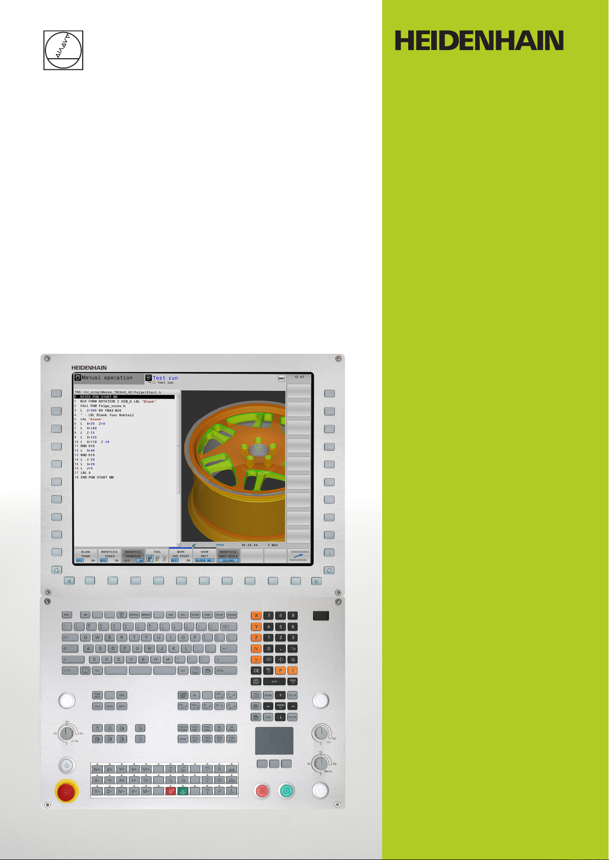
TNC 640
User’s Manual
DIN/ISO Programming
NC Software
340590-05
340591-05
340595-05
English (en)
1/2015
Page 2
Controls of the TNC
Controls of the TNC
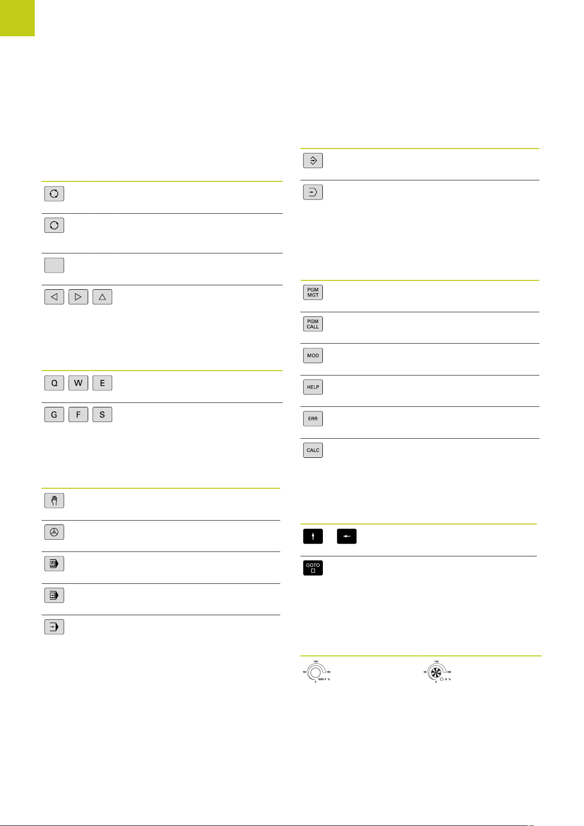
Keys on visual display unit
Key Function
Select split screen layout
Toggle the display between
machining and programming
modes
Soft keys for selecting functions on
screen
Shifting between soft-key rows
Alphanumeric keyboard
Key Function
File names, comments
DIN/ISO programming
Programming modes
Key Function
Programming
Test run
Program/file management, TNC functions
Key Function
Select or delete programs and files,
external data transfer
Define program call, select datum
and point tables
Select MOD functions
Display help text for NC error
messages, call TNCguide
Display all current error messages
Machine operating modes
Key Function
Manual operation
Electronic handwheel
Positioning with manual data input
Program run, single block
Program run, full sequence
Show calculator
Navigation keys
Key Function
Move highlight
Go directly to blocks, cycles and
parameter functions
Potentiometer for feed rate and spindle speed
Feed rate Spindle speed
2
TNC 640 | User's ManualDIN/ISO Programming | 1/2015
Page 3
NO
ENT
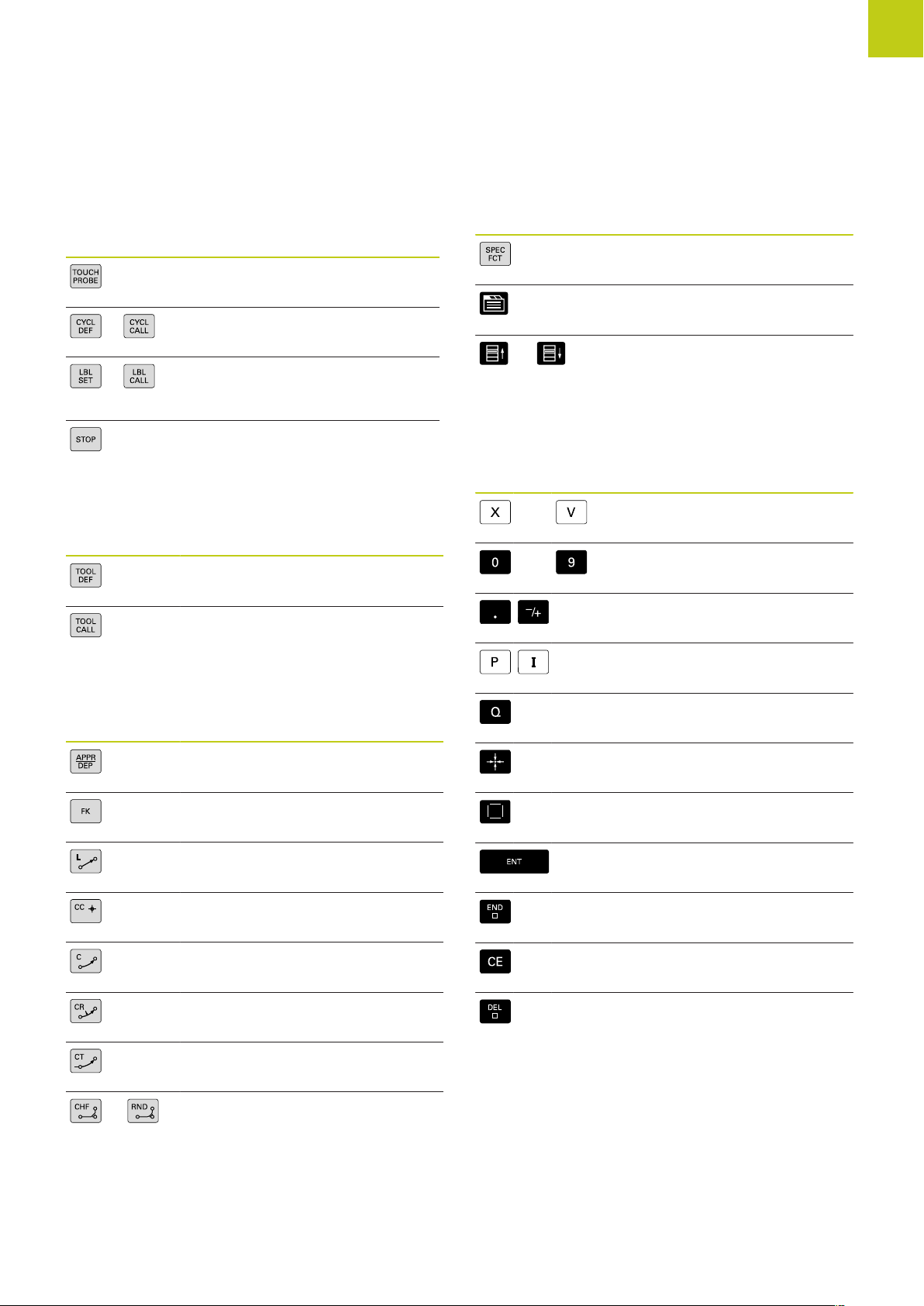
Cycles, subprograms and program section repeats
Key Function
Define touch probe cycles
Define and call cycles
Enter and call labels for
subprogramming and program
section repeats
Enter program stop in a program
Tool functions
Key Function
Define tool data in the program
Call tool data
Special functions
Key Function
Show special functions
Select the next tab in forms
Up/down one dialog box or button
Entering and editing coordinate axes and numbers
Key Function
Select coordinate axes or enter
. . .
. . .
them in a program
Numbers
Decimal point / Reverse algebraic
sign
Programming path movements
Key Function
Approach/depart contour
FK free contour programming
Straight line
Circle center/pole for polar
coordinates
Circular arc with center
Circle with radius
Circular arc with tangential
connection
Chamfer/Corner rounding
Polar coordinate input /
Incremental values
Q-parameter programming/
Q-parameter status
Save actual position or values from
calculator
Skip dialog questions, delete
words
Confirm entry and resume dialog
Conclude block and exit entry
Clear numerical entry or TNC error
message
Abort dialog, delete program
section
TNC 640 | User's ManualDIN/ISO Programming | 1/2015
3
Page 4

Controls of the TNC
4
TNC 640 | User's ManualDIN/ISO Programming | 1/2015
Page 5

Fundamentals
Page 6
Fundamentals
About this manual
About this manual
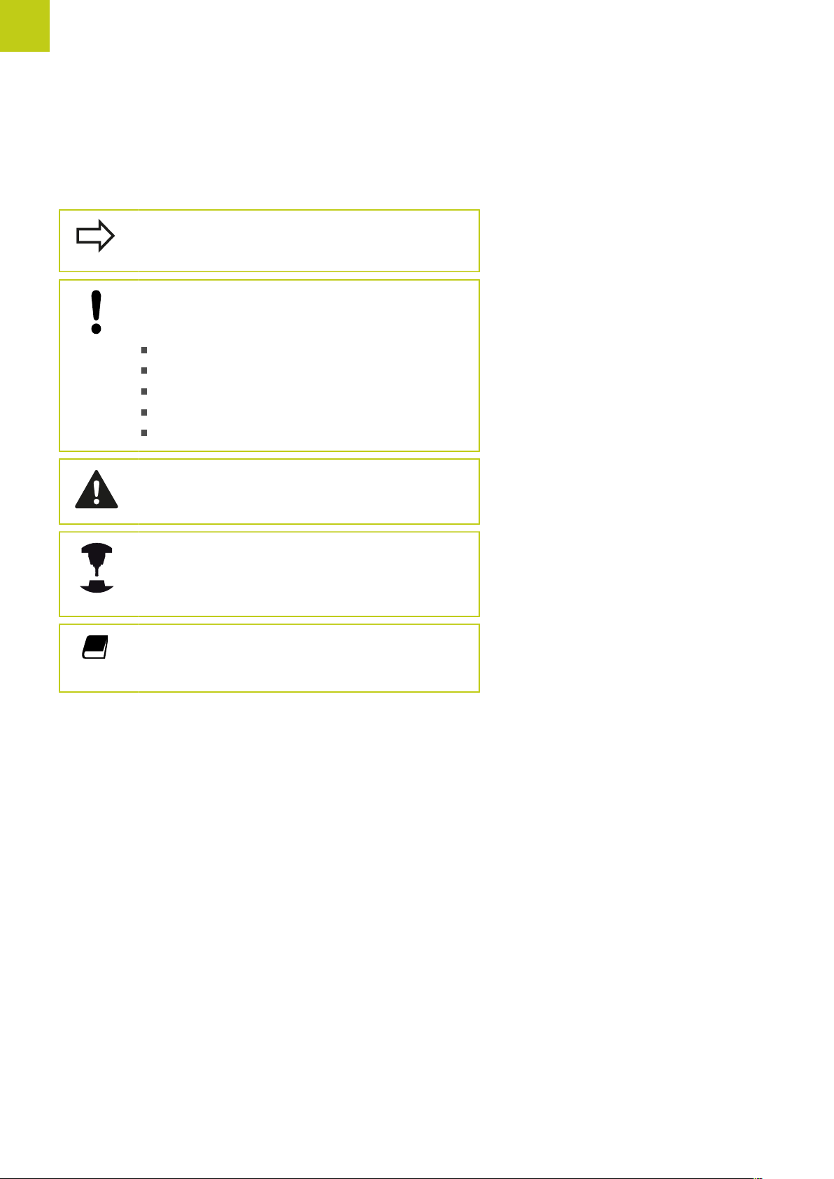
The symbols used in this manual are described below.
This symbol indicates that important information
about the function described must be considered.
This symbol indicates that there is one or more
of the following risks when using the described
function:
Danger to workpiece
Danger to fixtures
Danger to tool
Danger to machine
Danger to operator
This symbol indicates a possibly dangerous situation
that may cause injuries if not avoided.
This symbol indicates that the described function
must be adapted by the machine tool builder. The
function described may therefore vary depending on
the machine.
This symbol indicates that you can find detailed
information about a function in another manual.
Would you like any changes, or have you found any errors?
We are continuously striving to improve our documentation for you.
Please help us by sending your requests to the following e-mail
address: tnc-userdoc@heidenhain.de.
6
TNC 640 | User's ManualDIN/ISO Programming | 1/2015
Page 7

TNC model, software and features
TNC model, software and features
This manual describes functions and features provided by TNCs as
of the following NC software numbers.
TNC model NC software number
TNC 640 340590-05
TNC 640 E 340591-05
TNC 640 Programming Station 340595-05
The suffix E indicates the export version of the TNC. The export
version of the TNC has the following limitations:
Simultaneous linear movement in up to 4 axes
The machine tool builder adapts the usable features of the TNC to
his machine by setting machine parameters. Some of the functions
described in this manual may therefore not be among the features
provided by the TNC on your machine tool.
TNC functions that may not be available on your machine include:
Tool measurement with the TT
Please contact your machine tool builder to become familiar with
the features of your machine.
Many machine manufacturers, as well as HEIDENHAIN, offer
programming courses for the TNCs. We recommend these courses
as an effective way of improving your programming skill and
sharing information and ideas with other TNC users.
User's Manual for Cycle Programming:
All of the cycle functions (touch probe cycles and
fixed cycles) are described in the Cycle Programming
User’s Manual. Please contact HEIDENHAIN if you
require a copy of this User's Manual. ID: 892905-xx
TNC 640 | User's ManualDIN/ISO Programming | 1/2015
7
Page 8

Fundamentals
TNC model, software and features
Software options
The TNC 640 features various software options that can be enabled by your machine tool builder. Each option is to
be enabled separately and contains the following respective functions:
Hardware, options
■
1st additional axis for 4 axes plus spindle
■
2nd additional axis for 5 axes plus spindle
Software option 1 (option number 08)
Rotary table machining
Coordinate transformation
Interpolation
Software option 2 (option number 09)
3-D machining
Interpolation
HEIDENHAIN DNC (option number 18)
Display step (Option number 23)
step
■
■
■
■
■
■
■
■
■
■
■
■
■
Programming of cylindrical contours as if in two axes
Feed rate in distance per minute
Working plane, tilting the ...
Circle in 3 axes with tilted working plane (spacial arc)
Motion control with minimum jerk
3-D tool compensation through surface normal vectors
Using the electronic handwheel to change the angle of the swivel head
during program run without affecting the position of the tool point.
(TCPM = Tool Center Point Management)
Keeping the tool normal to the contour
Tool radius compensation perpendicular to traversing and tool direction
Linear in 5 axes (subject to export permit)
Communication with external PC applications over COM component
Linear axes to 0.01 µmInput resolution and display
Rotary axes to 0.00001°
Dynamic Collision Monitoring (DCM) software option (option number 40)
Collision monitoring in all
machine operating modes
Software option for additional conversational languages (option number 41)
Additional conversational
languages
8
The machine manufacturer defines objects to be monitored
■
Three warning levels in manual operation
■
Program interrupt during automatic operation
■
Includes monitoring of 5-axis movements
■
Slovenian
■
Norwegian
■
Slovak
■
Latvian
■
Korean
■
Estonian
■
Turkish
■
Romanian
■
TNC 640 | User's ManualDIN/ISO Programming | 1/2015
Page 9

TNC model, software and features
Software option for additional conversational languages (option number 41)
Lithuanian
■
DXF Converter software option (option number 42)
Extracting contour programs
and machining positions
from DXF data. Extracting
contour sections from plainlanguage programs.
Adaptive Feed Control (AFC) software option (option number 45)
Function for adaptive feed-
rate control for optimizing
the machining conditions
during series production
KinematicsOpt software option (option number 48)
Touch-probe cycles for
automatic testing and
optimization of the machine
kinematics
Mill-Turning software option (option number 50)
Functions for milling/turning
mode
Supported DXF format: AC1009 (AutoCAD R12)
■
For contours and point patterns
■
Simple and convenient specification of reference points
■
Select graphical features of contour sections from conversational
■
programs
Recording the actual spindle power by means of a teach-in cut
■
Defining the limits of automatic feed rate control
■
Fully automatic feed control during program run
■
Backup/restore active kinematics
■
Test active kinematics
■
Optimize active kinematics
■
Switching between Milling/Turning mode of operation
■
Constant cutting speed
■
Tool-tip radius compensation
■
Turning cycles
■
Extended Tool Managment software option (option number 93)
Extended tool management, python-based
■
Remote Desktop Manager software option (option number 133)
Windows on a separate computer unitRemote operation of
■
external computer units (e.g.
Windows PC) via the TNC
user interface
Incorporated in the TNC interface
■
TNC 640 | User's ManualDIN/ISO Programming | 1/2015
9
Page 10

Fundamentals
Cross Talk Compensation (CTC) software option (option number 141)
TNC model, software and features
Compensation of axis
couplings
Position Adaptive Control (PAC) software option (option number 142)
Changing control parameters
Load Adaptive Control (LAC) software option (option number 143)
parameters
Active Chatter Control (ACC) software option (option number 145)
Fully automatic function for chatter control during machining
Determination of dynamically caused position deviation through axis
■
acceleration
Compensation of the TCP
■
Changing of the control parameters depending on the position of the
■
axes in the working space
Changing of the control parameters depending on the speed or
■
acceleration of an axis
Automatic determination of workpiece weight and frictional forcesDynamic changing of control
■
Continuous adaptation of the parameters of the adaptive precontrolling
■
to the actual weight of the workpiece during machining
10
TNC 640 | User's ManualDIN/ISO Programming | 1/2015
Page 11

TNC model, software and features
Feature Content Level (upgrade functions)
Along with software options, significant further improvements
of the TNC software are managed via the Feature Content Level
upgrade functions. Functions subject to the FCL are not available
simply by updating the software on your TNC.
All upgrade functions are available to you without
surcharge when you receive a new machine.
Upgrade functions are identified in the manual with FCL n, where n
indicates the sequential number of the feature content level.
You can purchase a code number in order to permanently enable
the FCL functions. For more information, contact your machine tool
builder or HEIDENHAIN.
Intended place of operation
The TNC complies with the limits for a Class A device in
accordance with the specifications in EN 55022, and is intended for
use primarily in industrially-zoned areas.
Legal information
This product uses open source software. Further information is
available on the control under
Programming and Editing operating mode
MOD function
LICENSE INFO soft key
TNC 640 | User's ManualDIN/ISO Programming | 1/2015
11
Page 12

Fundamentals
TNC model, software and features
New functions
New functions 34059x-02
DXF files can be opened directly on the TNC in order to extract
contours and point patterns ("Programming: Data Transfer from
CAD Files", page 253).
The active tool-axis direction can now be activated in manual
mode and during handwheel superimposition as a virtual tool axis
("Superimposing handwheel positioning during program run: M118
", page 364).
The machine manufacturer can now define any areas on the
machine for collision monitoring ("Dynamic Collision Monitoring
(Option #40)", page 377).
Writing and reading data in freely definable tables ("Freely definable
tables", page 403).
The Adaptive Feed Control (AFC) function has been integrated
("Adaptive feed control AFC (Option #45)", page 384)
New touch probe cycle 484 for calibrating the wireless TT 449 tool
touch probe (see User's Manual for Cycles).
The new HR 520 and HR 550 FS handwheels are supported
("Traverse with electronic handwheels", page 484).
New machining cycle 225 ENGRAVING (see User’s Manual for
Cycle Programming)
New Active Chatter Control (ACC) software option ("Active Chatter
Control ACC (Option #145)", page 396).
New manual probing cycle "Center line as datum" ("Setting a center
line as datum ", page 531).
New function for rounding corners ("Rounding corners: M197",
page 371).
External access to the TNC can now be blocked with a MOD
function ("External access", page 579).
12
TNC 640 | User's ManualDIN/ISO Programming | 1/2015
Page 13

TNC model, software and features
Changed functions 34059x-02
The maximum number of characters for the NAME and DOC fields
in the tool table has been increased from 16 to 32 ("Enter tool data
into the table", page 172).
The columns AFC and ACC were added to the tool table ("Enter tool
data into the table", page 172).
Operation and positioning behavior of the manual probing cycles
has been improved ("Using 3-D touch probes ", page 509).
Predefined values can now be entered into a cycle parameter
with the PREDEF function in cycles (see User’s Manual for Cycle
Programming).
The status display has been expanded with the AFC tab ("Additional
status displays", page 77).
The FUNCTION TURNDATA SPIN rotational function has been
expanded with an input option for maximum speed ("Program
spindle speed", page 456).
A new optimization algorithm is now used with the KinematicsOpt
cycles (see User’s Manual for Cycle Programming).
With Cycle 257, circular stud milling, a parameter is now available
with which you can determine the approach position on the stud
(see User's Manual for Cycle Programming)
With Cycle 256, rectangular stud, a parameter is now available with
which you can determine the approach position on the stud (see
User's Manual for Cycle Programming).
With the "Basic Rotation" probing cycle, workpiece misalignment
can now be compensated for via a table rotation ("Compensation of
workpiece misalignment by rotating the table", page 524)
TNC 640 | User's ManualDIN/ISO Programming | 1/2015
13
Page 14

Fundamentals
TNC model, software and features
New functions 34059x-04
New special operating mode ("Retraction after a power
interruption", page 567).
New graphic simulation ("Graphics ", page 548).
New MOD function "tool usage file" within the machine settings
group ("Tool usage file", page 582).
New MOD function "set system time" within the systems settings
group ("Set the system time", page 584).
New MOD group "graphic settings" ("Graphic settings",
page 578).
With the new syntax for the adaptive feed control (AFC) you
can start or end a teach-in step ("Recording a teach-in cut",
page 388).
With the new cutting data calculator you can calculate the spindle
speed and the feed rate ("Cutting data calculator", page 147).
In the TURNDATA function, you can now define the effect of
the tool compensation ("Tool compensation in the program",
page 462).
Now you can activate and deactivate the active chatter
compensation (ACC) by soft key ("Activating/deactivating ACC",
page 397).
New if/then decisions were introduced in the jump commands
("Programming if-then decisions", page 301).
The character set of the fixed cycle 225 Engraving was expanded
by more characters and the diameter sign (see User's Manual for
Cycle Programming).
New fixed cycle 275 Trochoidal Milling (see User’s Manual for Cycle
Programming)
New fixed cycle 233 ENGRAVING (see User’s Manual for Cycle
Programming)
In the drilling cycles 200, 203 and 205 the parameter Q395 DEPTH
REFERENCE was introduced in order to evaluate the T ANGLE (see
User's Manual for Cycle Programming).
The probing cycle 4 MEASURING IN 3-D was introduced (see
User's Manual for Cycle Programming).
14
TNC 640 | User's ManualDIN/ISO Programming | 1/2015
Page 15

TNC model, software and features
Changed functions 34059x-04
The turning tool table was expanded by the column NAME ("Tool
data", page 463).
Now up to 4 functions are allowed in an NC block ("Fundamentals",
page 352).
New soft keys for value transfer have been introduced in the pocket
calculator ("Operation", page 144).
The distance-to-go display can now also be displayed in the input
system ("Select the position display", page 585).
Cycle 241 SINGLE-LIP DEEP HOLE DRILLING was expanded
by several input parameters (see User's Manual for Cycle
Programming).
Cycle 404 was expanded by the parameter Q305 NUMBER IN
TABLE (see User's Manual for Cycle Programming).
In the thread milling cycles 26x an approaching feed rate was
introduced (see User's Manual for Cycle Programming).
In Cycle 205 Universal Pecking you can now use parameter Q208
to define a feed rate for retraction (see User's Manual for Cycle
Programming).
TNC 640 | User's ManualDIN/ISO Programming | 1/2015
15
Page 16

Fundamentals
TNC model, software and features
New functions 34059x-05
The tool management was expanded by the column PITCH ("Enter
tool data into the table", page 172).
The turning tool table was expanded by the columns YL and DYL
("Tool data", page 463).
In the tool management, several lines can now be added at the end
of the table ("Tool management (Option #93)", page 190).
Any turning tool table can be selected for the program test ("Test
Run", page 560).
Programs with .HU and .HC endings can be selected and
processed in all operating modes.
The functions and have been added ("Calling any program as a
subprogram").
New FEED DWELL function for programming repeating dwell times
("Dwell time FUNCTION FEED DWELL").
The control automatically writes upper case letters at the start of a
block "Programming path functions", page 220.
The D18 functions have been expanded ("D18: Reading system
data", page 313).
The DCM function can be activated and deactivated from the
NC program ("Activating and deactivating collision monitoring",
page 382).
USB data carriers can be locked with the SELinux security software
("SELinux security software", page 90).
The posAfterContPocket machine parameter has been added that
influences positioning after an SL cycle ("Machine-specific user
parameters", page 608).
Protective zones can be defined in the MOD menu ("Entering
traverse limits", page 581).
Write protection is possible for single lines in the preset table
("Saving the datums in the preset table", page 501).
New manual probing function for aligning a plane ("Measuring 3-D
basic rotation", page 525).
New function for aligning the machining plane without rotary axes
("Tilt the working plane without rotary axes", page 434).
CAD files can be opened without Option #42 ("CAD Viewer",
page 255).
New software option #131 Spindle Sychronism ("Software options",
page 8).
16
TNC 640 | User's ManualDIN/ISO Programming | 1/2015
Page 17

TNC model, software and features
Modified functions 34059x-05
With tool selection, the control also displays columns XL and
ZL from the turning tool table in the pop-up window ("Tool call",
page 461).
The input range of the DOC column in the pocket table has been
expanded to 32 characters ("Pocket table for tool changer").
Commands D15, D31 and D32 from predecessor controls no
longer generate ERROR blocks during import. When simulating
or running an NC program with these commands, the control
interrupts the NC program with an error message that helps you to
find an alternative implementation.
Miscellaneous functions M104, M105, M112, M114, M124, M134,
M142, M150, M200 - M204 from predecessor controls no longer
generate ERROR blocks during import. When simulating or running
an NC program with these miscellaneous functions, the control
interrupts the NC program with an error message that helps you
to find an alternative implementation ("Comparison: Miscellaneous
functions").
The maximum file size of files output with D16 F-Print has been
increased from 4kB to 20kB.
The Preset.PR preset table is write-protected in Programming
operating mode ("Saving the datums in the preset table").
The input range of the Q parameter list for defining the QPARA tab
on the status display consists of 132 input positions ("Displaying Q
parameters (QPARA tab)", page 82).
Manual calibration of the touch probe with less pre-positionings
("Calibrating a 3-D touch trigger probe ").
The position display takes into account the DL oversizes
programmed in the T block, selectable as an oversize of the
workpiece or tool ("Delta values for lengths and radii", page 171).
In single blocks, the control executes each point singly with point
pattern cycles and G79 PAT ("Program run", page 562).
Rebooting the control is no longer possible with the END key, but
with the soft key ("Switch-off", page 482).
The control displays the contouring feed rate in manual mode
("Spindle speed S, feed rate F and miscellaneous function M",
page 494).
Deactivate tilting in manual mode is only possible via the 3D-ROT
menu ("To activate manual tilting:", page 538).
The machine parameter maxLineGeoSearch has been increased
to a maximum of 100000 ("Machine-specific user parameters",
page 608).
The names of the software options #8, #9 and #21 have been
changed ("Software options", page 8).
TNC 640 | User's ManualDIN/ISO Programming | 1/2015
17
Page 18

Fundamentals
TNC model, software and features
New and modified cycle functions 34059x-05
New cycle G880 (Option #50), see "ZAHNRAD ABWÄLZFRÄSEN
(Zyklus 880, DIN/ISO: G880)"
New cycle G292 (Option #96), see "INTERPOLATIONSDREHEN
KONTURSCHLICHTEN (Zyklus 292, DIN/ISO: G292, Softwareoption
96)"
New cycle G291 COUPLG.TURNG.INTERP. (Option #96), see
"INTERPOLATIONSDREHEN KOPPLUNG (Zyklus 291, DIN/ISO:
G291, Softwareoption 96)"
New cycle G239 for LAC (Load Adapt. Control) load-dependent
adaptation of control parameters (Option #143), see "BELADUNG
ERMITTELN (Zyklus 239 DIN/ISO: G239, Software-Option 143)"
Cycle G270 CONTOUR TRAIN DATA has been added (Option #19),
see "KONTURZUG-DATEN (Zyklus 270, DIN/ISO: G270, SoftwareOption 19)"
Cycle G139 has been added (Option #1), see "ZYLINDER-MANTEL
(Zyklus 39, DIN/ISO: G139, Software-Option 1)"
The character set of machining cycle G225 has been expanded
with the CE character, ß, the @ character and system time, see
"ENGRAVING (Cycle 225, DIN/ISO: G225)"
Cycles G252-G254 have been expanded with the optional
parameter Q439
Cycle G122 has been expanded with the optional parameters
Q401, Q404, see "ROUGHING (Cycle 22, DIN/ISO: G122, software
option 19)"
Cycle G484 has been expanded with the optional parameter Q536,
see "Calibrate the wireless TT 449 (Cycle 484, DIN/ISO: G484,
software option 17 Touch Probe Functions software option 17)"
Cycles G841 SIMPLE REC. TURNG., RADIAL DIR., G842 , G851 ,
G852 have been expanded with plunge feed rate Q488
Eccentric turning with cycle G800 is possible with Option #50,
see "ADAPT ROTARY COORDINATE SYSTEM(Cycle 800, DIN/ISO:
G800)"
18
TNC 640 | User's ManualDIN/ISO Programming | 1/2015
Page 19

Contents
1 First Steps with the TNC 640....................................................................................................... 49
2 Introduction.....................................................................................................................................69
3 Programming: Fundamentals, File Management........................................................................93
4 Programming: Programming aids.............................................................................................. 139
5 Programming: Tools..................................................................................................................... 167
6 Programming: Programming contours...................................................................................... 203
7 Programming: Data Transfer from CAD Files............................................................................ 253
8 Programming: Subprograms and program section repeats.................................................... 273
9 Programming: Q Parameters.......................................................................................................291
10 Programming: Miscellaneous functions.....................................................................................351
11 Programming: Special functions.................................................................................................373
12 Programming: Multiple Axis Machining.................................................................................... 411
13 Programming: Pallet editor......................................................................................................... 445
14 Programming: Turning Operations............................................................................................. 451
15 Manual operation and setup.......................................................................................................479
16 Positioning with Manual Data Input.......................................................................................... 541
17 Test run and program run........................................................................................................... 547
18 MOD functions..............................................................................................................................575
19 Tables and overviews...................................................................................................................607
TNC 640 | User's ManualDIN/ISO Programming | 1/2015
19
Page 20

Contents
20
TNC 640 | User's ManualDIN/ISO Programming | 1/2015
Page 21

1 First Steps with the TNC 640....................................................................................................... 49
1.1 Overview................................................................................................................................................ 50
1.2 Machine switch-on................................................................................................................................50
Acknowledging the power interruption and moving to the reference points..........................................50
1.3 Programming the first part..................................................................................................................51
Selecting the correct operating mode.................................................................................................... 51
The most important TNC keys................................................................................................................51
Opening a new program/file management.............................................................................................52
Defining a workpiece blank.................................................................................................................... 53
Program layout........................................................................................................................................ 54
Programming a simple contour...............................................................................................................55
Creating a cycle program........................................................................................................................58
1.4 Graphically testing the first part.........................................................................................................60
Selecting the correct operating mode.................................................................................................... 60
Selecting the tool table for the test run.................................................................................................60
Choosing the program you want to test................................................................................................ 61
Selecting the screen layout and the view.............................................................................................. 61
Starting the test run................................................................................................................................62
1.5 Setting up tools.................................................................................................................................... 63
Selecting the correct operating mode.................................................................................................... 63
Preparing and measuring tools............................................................................................................... 63
The tool table TOOL.T............................................................................................................................ 64
The pocket table TOOL_P.TCH................................................................................................................65
1.6 Workpiece setup....................................................................................................................................66
Selecting the correct operating mode.................................................................................................... 66
Clamping the workpiece......................................................................................................................... 66
Datum setting with 3-D touch probe...................................................................................................... 67
1.7 Running the first program................................................................................................................... 68
Selecting the correct operating mode.................................................................................................... 68
Choosing the program you want to run................................................................................................. 68
Start the program....................................................................................................................................68
TNC 640 | User's ManualDIN/ISO Programming | 1/2015
21
Page 22

Contents
2 Introduction.....................................................................................................................................69
2.1 The TNC 640..........................................................................................................................................70
Programming: In HEIDENHAIN conversational and DIN/ISO..................................................................70
Compatibility............................................................................................................................................70
2.2 Visual display unit and operating panel............................................................................................ 71
Display screen.........................................................................................................................................71
Setting the screen layout........................................................................................................................71
Control Panel...........................................................................................................................................72
2.3 Modes of Operation..............................................................................................................................73
Manual Operation and El. Handwheel....................................................................................................73
Positioning with Manual Data Input........................................................................................................73
Programming........................................................................................................................................... 74
Test Run.................................................................................................................................................. 74
Program Run, Full Sequence and Program Run, Single Block................................................................75
2.4 Status displays...................................................................................................................................... 76
General status display.............................................................................................................................76
Additional status displays........................................................................................................................77
2.5 Window Manager..................................................................................................................................84
Task bar................................................................................................................................................... 85
2.6 Remote Desktop Manager (Option #133)........................................................................................... 86
Introduction............................................................................................................................................. 86
Configuring connections – Windows Terminal Service.......................................................................... 86
Configuring the connection – VNC......................................................................................................... 88
Starting and stopping the connection.....................................................................................................89
2.7 SELinux security software....................................................................................................................90
2.8 Accessories: HEIDENHAIN 3-D Touch Probes and Electronic Handwheels......................................91
3-D touch probes.................................................................................................................................... 91
HR electronic handwheels...................................................................................................................... 92
22
TNC 640 | User's ManualDIN/ISO Programming | 1/2015
Page 23

3 Programming: Fundamentals, File Management........................................................................93
3.1 Fundamentals........................................................................................................................................ 94
Position encoders and reference marks................................................................................................. 94
Reference system................................................................................................................................... 94
Reference system on milling machines..................................................................................................95
Designation of the axes on milling machines.........................................................................................95
Polar coordinates..................................................................................................................................... 96
Absolute and incremental workpiece positions......................................................................................97
Selecting the datum................................................................................................................................98
3.2 Opening programs and entering......................................................................................................... 99
Organization of an NC program in DIN/ISO format................................................................................ 99
Define the blank: G30/G31................................................................................................................... 100
Opening a new part program............................................................................................................... 103
Programming tool movements in DIN/ISO...........................................................................................104
Actual position capture..........................................................................................................................105
Editing a program..................................................................................................................................106
The TNC search function...................................................................................................................... 109
3.3 File Management: Fundamentals......................................................................................................111
Files....................................................................................................................................................... 111
Displaying externally generated files on the TNC.................................................................................113
Data Backup.......................................................................................................................................... 113
TNC 640 | User's ManualDIN/ISO Programming | 1/2015
23
Page 24

Contents
3.4 Working with the File Manager.........................................................................................................114
Directories............................................................................................................................................. 114
Paths......................................................................................................................................................114
Overview: Functions of the file manager............................................................................................. 115
Calling the File Manager....................................................................................................................... 116
Selecting drives, directories and files...................................................................................................117
Creating a new directory...................................................................................................................... 118
Creating a new file................................................................................................................................118
Copying a single file..............................................................................................................................118
Copying files into another directory......................................................................................................119
Copying a table..................................................................................................................................... 120
Copying a directory...............................................................................................................................120
Choosing one of the last files selected................................................................................................121
Deleting a file........................................................................................................................................122
Deleting a directory...............................................................................................................................122
Tagging files.......................................................................................................................................... 123
Renaming a file..................................................................................................................................... 124
Sorting files........................................................................................................................................... 124
Additional functions...............................................................................................................................125
Additional tools for management of external file types........................................................................126
Data transfer to/from an external data medium................................................................................... 133
The TNC in a network.......................................................................................................................... 135
USB devices on the TNC......................................................................................................................136
24
TNC 640 | User's ManualDIN/ISO Programming | 1/2015
Page 25

4 Programming: Programming aids.............................................................................................. 139
4.1 Adding comments...............................................................................................................................140
Application............................................................................................................................................. 140
Entering comments during programming.............................................................................................140
Inserting comments after program entry............................................................................................. 140
Entering a comment in a separate block..............................................................................................140
Functions for editing of the comment..................................................................................................141
4.2 Display of NC Programs.....................................................................................................................142
Syntax highlighting................................................................................................................................ 142
Scrollbar.................................................................................................................................................142
4.3 Structuring programs..........................................................................................................................143
Definition and applications.................................................................................................................... 143
Displaying the program structure window / Changing the active window............................................143
Inserting a structuring block in the program window...........................................................................143
Selecting blocks in the program structure window.............................................................................. 143
4.4 Calculator............................................................................................................................................. 144
Operation...............................................................................................................................................144
4.5 Cutting data calculator.......................................................................................................................147
Application............................................................................................................................................. 147
4.6 Programming graphics....................................................................................................................... 150
Generate/do not generate graphics during programming.....................................................................150
Generating a graphic for an existing program...................................................................................... 151
Block number display ON/OFF..............................................................................................................152
Erasing the graphic............................................................................................................................... 152
Showing grid lines.................................................................................................................................152
Magnification or reduction of details.................................................................................................... 153
TNC 640 | User's ManualDIN/ISO Programming | 1/2015
25
Page 26

Contents
4.7 Error messages.................................................................................................................................... 154
Display of errors....................................................................................................................................154
Open the error window........................................................................................................................ 154
Closing the error window..................................................................................................................... 154
Detailed error messages.......................................................................................................................155
INTERNAL INFO soft key......................................................................................................................155
Clearing errors.......................................................................................................................................156
Error log.................................................................................................................................................156
Keystroke log.........................................................................................................................................157
Informational texts................................................................................................................................ 158
Saving service files............................................................................................................................... 158
Calling the TNCguide help system....................................................................................................... 158
4.8 TNCguide context-sensitive help system.........................................................................................159
Application............................................................................................................................................. 159
Working with the TNCguide................................................................................................................. 160
Downloading current help files.............................................................................................................164
26
TNC 640 | User's ManualDIN/ISO Programming | 1/2015
Page 27

5 Programming: Tools..................................................................................................................... 167
5.1 Entering tool-related data.................................................................................................................. 168
Feed rate F............................................................................................................................................168
Spindle speed S.................................................................................................................................... 169
5.2 Tool data...............................................................................................................................................170
Requirements for tool compensation................................................................................................... 170
Tool number, tool name........................................................................................................................ 170
Tool length L......................................................................................................................................... 170
Tool radius R......................................................................................................................................... 170
Delta values for lengths and radii.........................................................................................................171
Entering tool data into the program..................................................................................................... 171
Enter tool data into the table............................................................................................................... 172
Importing tool tables.............................................................................................................................180
Pocket table for tool changer................................................................................................................181
Call tool data......................................................................................................................................... 184
Tool change........................................................................................................................................... 186
Tool usage test......................................................................................................................................188
Tool management (Option #93)............................................................................................................ 190
5.3 Tool compensation..............................................................................................................................198
Introduction........................................................................................................................................... 198
Tool length compensation..................................................................................................................... 198
Tool radius compensation..................................................................................................................... 199
TNC 640 | User's ManualDIN/ISO Programming | 1/2015
27
Page 28

Contents
6 Programming: Programming contours...................................................................................... 203
6.1 Tool movements..................................................................................................................................204
Path functions....................................................................................................................................... 204
FK free contour programming.............................................................................................................. 204
Miscellaneous functions M...................................................................................................................204
Subprograms and program section repeats......................................................................................... 205
Programming with Q parameters......................................................................................................... 205
6.2 Fundamentals of Path Functions.......................................................................................................206
Programming tool movements for workpiece machining.....................................................................206
6.3 Approaching and departing a contour............................................................................................. 209
Starting point and end point................................................................................................................. 209
Tangential approach and departure....................................................................................................... 211
Overview: Types of paths for contour approach and departure............................................................212
Important positions for approach and departure...................................................................................213
Approaching on a straight line with tangential connection: APPR LT................................................... 214
Approaching on a straight line perpendicular to the first contour point: APPR LN............................... 215
Approaching on a circular path with tangential connection: APPR CT..................................................216
Approaching on a circular path with tangential connection from a straight line to the contour:
APPR LCT.............................................................................................................................................. 217
Departing in a straight line with tangential connection: DEP LT.......................................................... 218
Departing in a straight line perpendicular to the last contour point: DEP LN....................................... 218
Departing on a circular path with tangential connection: DEP CT........................................................219
Departing on a circular arc tangentially connecting the contour and a straight line: DEP LCT.............. 219
6.4 Path contours - Cartesian coordinates............................................................................................. 220
Overview of path functions.................................................................................................................. 220
Programming path functions.................................................................................................................220
28
Straight line in rapid traverse G00 or straight line with feed rate F G01.............................................. 221
Inserting a chamfer between two straight lines...................................................................................222
Corner rounding G25............................................................................................................................ 223
Circle center I, J................................................................................................................................... 224
Circular path C around circle center CC............................................................................................... 225
CircleG02/G03/G05 with defined radius............................................................................................... 226
Circle G06 with tangential connection..................................................................................................228
Example: Linear movements and chamfers with Cartesian coordinates.............................................. 229
Example: Circular movements with Cartesian coordinates.................................................................. 230
Example: Full circle with Cartesian coordinates................................................................................... 231
TNC 640 | User's ManualDIN/ISO Programming | 1/2015
Page 29

6.5 Path contours – Polar coordinates....................................................................................................232
Overview............................................................................................................................................... 232
Zero point for polar coordinates: pole I, J............................................................................................ 233
Straight line in rapid traverse G10 or straight line with feed rate F G11...............................................233
Circular path G12/G13/G15 around pole I, J......................................................................................... 234
Circle G16 with tangential connection..................................................................................................234
Helix.......................................................................................................................................................235
Example: Linear movement with polar coordinates............................................................................. 237
Example: Helix...................................................................................................................................... 238
6.6 Path contours – FK free contour programming...............................................................................239
Fundamentals........................................................................................................................................ 239
FK programming graphics..................................................................................................................... 241
Initiating the FK dialog.......................................................................................................................... 242
Pole for FK programming...................................................................................................................... 242
Free straight line programming.............................................................................................................243
Free circular path programming............................................................................................................ 244
Input options......................................................................................................................................... 245
Auxiliary points...................................................................................................................................... 248
Relative data..........................................................................................................................................249
Example: FK programming 1................................................................................................................ 251
TNC 640 | User's ManualDIN/ISO Programming | 1/2015
29
Page 30

Contents
7 Programming: Data Transfer from CAD Files............................................................................ 253
7.1 CAD viewer and DXF converter screen layout.................................................................................254
CAD viewer and DXF converter screen layout..................................................................................... 254
7.2 CAD Viewer..........................................................................................................................................255
Application............................................................................................................................................. 255
7.3 DXF converter (Option #42)............................................................................................................... 256
Application............................................................................................................................................. 256
Working with the DXF converter..........................................................................................................257
Opening a DXF file............................................................................................................................... 257
Basic settings........................................................................................................................................258
Setting layers.........................................................................................................................................260
Defining the datum............................................................................................................................... 261
Selecting and saving a contour.............................................................................................................263
Selecting and saving machining positions............................................................................................ 267
30
TNC 640 | User's ManualDIN/ISO Programming | 1/2015
Page 31

8 Programming: Subprograms and program section repeats.................................................... 273
8.1 Labeling Subprograms and Program Section Repeats................................................................... 274
Label......................................................................................................................................................274
8.2 Subprograms....................................................................................................................................... 275
Operating sequence..............................................................................................................................275
Programming notes...............................................................................................................................275
Programming a subprogram................................................................................................................. 275
Calling a subprogram............................................................................................................................ 276
8.3 Program-section repeats.................................................................................................................... 277
Label G98.............................................................................................................................................. 277
Operating sequence..............................................................................................................................277
Programming notes...............................................................................................................................277
Programming a program section repeat............................................................................................... 278
Calling a program section repeat..........................................................................................................278
8.4 Any desired program as subprogram............................................................................................... 279
Overview of the soft keys.................................................................................................................... 279
Operating sequence..............................................................................................................................280
Programming notes...............................................................................................................................280
Calling any program as a subprogram..................................................................................................281
8.5 Nesting................................................................................................................................................. 283
Types of nesting....................................................................................................................................283
Nesting depth........................................................................................................................................283
Subprogram within a subprogram........................................................................................................ 284
Repeating program section repeats......................................................................................................285
Repeating a subprogram.......................................................................................................................286
8.6 Programming examples..................................................................................................................... 287
Example: Milling a contour in several infeeds...................................................................................... 287
Example: Groups of holes.................................................................................................................... 288
Example: Group of holes with several tools.........................................................................................289
TNC 640 | User's ManualDIN/ISO Programming | 1/2015
31
Page 32

Contents
9 Programming: Q Parameters.......................................................................................................291
9.1 Principle and overview of functions................................................................................................. 292
Programming notes...............................................................................................................................294
Calling Q parameter functions.............................................................................................................. 295
9.2 Part families—Q parameters in place of numerical values............................................................. 296
Application............................................................................................................................................. 296
9.3 Describing contours with mathematical functions......................................................................... 297
Application............................................................................................................................................. 297
Overview............................................................................................................................................... 297
Programming fundamental operations..................................................................................................298
9.4 Angle functions................................................................................................................................... 299
Definitions............................................................................................................................................. 299
Programming trigonometric functions.................................................................................................. 299
9.5 Calculation of circles...........................................................................................................................300
Application............................................................................................................................................. 300
9.6 If-then decisions with Q parameters................................................................................................ 301
Application............................................................................................................................................. 301
Unconditional jumps..............................................................................................................................301
Programming if-then decisions............................................................................................................. 301
9.7 Checking and changing Q parameters............................................................................................. 302
Procedure.............................................................................................................................................. 302
9.8 Additional functions............................................................................................................................304
32
Overview............................................................................................................................................... 304
D14: Displaying error messages........................................................................................................... 305
D16 – Formatted output of text and Q parameter values.....................................................................309
D18: Reading system data....................................................................................................................313
D19 – Transfer values to the PLC.........................................................................................................322
D20 – NC and PLC synchronization......................................................................................................322
D29 – Transfer values to the PLC.........................................................................................................323
D37 – EXPORT......................................................................................................................................323
TNC 640 | User's ManualDIN/ISO Programming | 1/2015
Page 33

9.9 Entering formulas directly..................................................................................................................324
Entering formulas..................................................................................................................................324
Rules for formulas.................................................................................................................................326
Programming example.......................................................................................................................... 327
9.10 String parameters............................................................................................................................... 328
String processing functions.................................................................................................................. 328
Assigning string parameters................................................................................................................. 329
Chain-linking string parameters.............................................................................................................329
Converting a numerical value to a string parameter.............................................................................330
Copying a substring from a string parameter.......................................................................................331
Converting a string parameter to a numerical value.............................................................................332
Checking a string parameter.................................................................................................................333
Finding the length of a string parameter..............................................................................................334
Comparing alphabetic sequence...........................................................................................................335
Reading out machine parameters......................................................................................................... 336
9.11 Preassigned Q parameters.................................................................................................................339
Values from the PLC: Q100 to Q107....................................................................................................339
Active tool radius: Q108........................................................................................................................339
Tool axis: Q109......................................................................................................................................339
Spindle status: Q110.............................................................................................................................340
Coolant on/off: Q111............................................................................................................................. 340
Overlap factor: Q112............................................................................................................................. 340
Unit of measurement for dimensions in the program: Q113................................................................340
Tool length: Q114.................................................................................................................................. 340
Coordinates after probing during program run..................................................................................... 341
Deviation between actual value and nominal value during automatic tool measurement with the TT
130.........................................................................................................................................................341
Tilting the working plane with mathematical angles: rotary axis coordinates calculated by the
TNC........................................................................................................................................................341
Measurement results from touch probe cycles (see also User’s Manual for Cycle Programming).......342
9.12 Programming examples..................................................................................................................... 344
Example: Ellipse.................................................................................................................................... 344
Example: Concave cylinder machined with spherical cutter.................................................................346
Example: Convex sphere machined with end mill................................................................................348
TNC 640 | User's ManualDIN/ISO Programming | 1/2015
33
Page 34

Contents
10 Programming: Miscellaneous functions.....................................................................................351
10.1 Entering miscellaneous functions M and STOP...............................................................................352
Fundamentals........................................................................................................................................ 352
10.2 M functions for program run inspection, spindle and coolant.......................................................353
Overview............................................................................................................................................... 353
10.3 Miscellaneous functions for coordinate data...................................................................................354
Programming machine-referenced coordinates: M91/M92.................................................................. 354
Moving to positions in a non-tilted coordinate system with a tilted working plane: M130...................356
10.4 Miscellaneous functions for path behavior......................................................................................357
Machining small contour steps: M97................................................................................................... 357
Machining open contour corners: M98................................................................................................ 358
Feed rate factor for plunging movements: M103.................................................................................359
Feed rate in millimeters per spindle revolution: M136.........................................................................360
Feed rate for circular arcs: M109/M110/M111.......................................................................................361
Calculating the radius-compensated path in advance (LOOK AHEAD): M120......................................362
Superimposing handwheel positioning during program run: M118...................................................... 364
Retraction from the contour in the tool-axis direction: M140...............................................................366
Suppressing touch probe monitoring: M141........................................................................................ 368
Deleting basic rotation: M143...............................................................................................................369
Automatically retract tool from the contour at an NC stop: M148....................................................... 370
Rounding corners: M197.......................................................................................................................371
34
TNC 640 | User's ManualDIN/ISO Programming | 1/2015
Page 35

11 Programming: Special functions.................................................................................................373
11.1 Overview of special functions........................................................................................................... 374
Main menu for SPEC FCT special functions........................................................................................ 374
Program defaults menu........................................................................................................................ 375
Functions for contour and point machining menu................................................................................ 375
Menu of various DIN/ISO functions......................................................................................................376
11.2 Dynamic Collision Monitoring (Option #40).....................................................................................377
Function.................................................................................................................................................377
Graphic display of the collision objects................................................................................................ 378
Collision monitoring in the manual operating modes........................................................................... 380
Collision monitoring in the Program Run operating modes..................................................................381
Activating and deactivating collision monitoring................................................................................... 382
11.3 Adaptive feed control AFC (Option #45).......................................................................................... 384
Application............................................................................................................................................. 384
Defining the AFC basic settings........................................................................................................... 386
Recording a teach-in cut....................................................................................................................... 388
Activating/deactivating AFC...................................................................................................................392
Log file.................................................................................................................................................. 393
Tool breakage/tool wear monitoring......................................................................................................394
Spindle load monitoring........................................................................................................................ 395
11.4 Active Chatter Control ACC (Option #145).......................................................................................396
Application............................................................................................................................................. 396
Activating/deactivating ACC...................................................................................................................397
11.5 Defining DIN/ISO Functions...............................................................................................................398
Overview............................................................................................................................................... 398
11.6 Creating Text Files...............................................................................................................................399
Application............................................................................................................................................. 399
Opening and exiting text files...............................................................................................................399
Editing texts.......................................................................................................................................... 400
Deleting and re-inserting characters, words and lines..........................................................................400
Editing text blocks.................................................................................................................................401
Finding text sections.............................................................................................................................402
TNC 640 | User's ManualDIN/ISO Programming | 1/2015
35
Page 36

Contents
11.7 Freely definable tables....................................................................................................................... 403
Fundamentals........................................................................................................................................ 403
Creating a freely definable table...........................................................................................................403
Editing the table format........................................................................................................................404
Switching between table and form view..............................................................................................405
D26 – Open a freely definable table.................................................................................................... 406
D27 – Write to a freely definable table................................................................................................ 407
D28 – Read from a freely definable table............................................................................................ 408
11.8 Dwell time FUNCTION FEED DWELL................................................................................................409
Programming dwell time.......................................................................................................................409
Resetting dwell time............................................................................................................................. 410
36
TNC 640 | User's ManualDIN/ISO Programming | 1/2015
Page 37

12 Programming: Multiple Axis Machining.................................................................................... 411
12.1 Functions for multiple axis machining............................................................................................. 412
12.2 The PLANE Function: Tilting the working plane (Software Option 8)........................................... 413
Introduction........................................................................................................................................... 413
Overview............................................................................................................................................... 414
Defining the PLANE function................................................................................................................415
Position display......................................................................................................................................415
Resetting the PLANE function.............................................................................................................. 416
Defining the working plane with the spatial angle: PLANE SPATIAL....................................................417
Defining the working plane with the projection angle: PLANE PROJECTED....................................... 419
Defining the working plane with the Euler angle: PLANE EULER........................................................420
Defining the working plane with two vectors: PLANE VECTOR.......................................................... 422
Defining the working plane via three points: PLANE POINTS..............................................................424
Defining the working plane via a single incremental spatial angle: PLANE SPATIAL............................426
Tilting the working plane through axis angle: PLANE AXIAL (FCL 3 function)......................................427
Specifying the positioning behavior of the PLANE function.................................................................429
Tilt the working plane without rotary axes...........................................................................................434
12.3 Inclined-tool machining in a tilted plane (Option #9)..................................................................... 435
Function.................................................................................................................................................435
Inclined-tool machining via incremental traverse of a rotary axis......................................................... 435
12.4 Miscellaneous functions for rotary axes.......................................................................................... 436
Feed rate in mm/min on rotary axes A, B, C: M116 (Option #8).......................................................... 436
Shortest-path traverse of rotary axes: M126........................................................................................437
Reducing display of a rotary axis to a value less than 360°: M94........................................................438
Maintaining the position of the tool tip when positioning with tilted axes (TCPM): M128
(Option #9).............................................................................................................................................439
Selecting tilting axes: M138................................................................................................................. 442
Compensating the machine’s kinematics configuration for ACTUAL/NOMINAL positions at end of block:
M144 (Option #9).................................................................................................................................. 443
12.5 Peripheral Milling: 3-D radius compensation with M128 and radius compensation (G41/
G42).......................................................................................................................................................444
Application............................................................................................................................................. 444
TNC 640 | User's ManualDIN/ISO Programming | 1/2015
37
Page 38

Contents
13 Programming: Pallet editor......................................................................................................... 445
13.1 Pallet management............................................................................................................................. 446
Application............................................................................................................................................. 446
Select pallet table................................................................................................................................. 448
Exiting the pallet file............................................................................................................................. 448
Run pallet file........................................................................................................................................ 448
38
TNC 640 | User's ManualDIN/ISO Programming | 1/2015
Page 39

14 Programming: Turning Operations............................................................................................. 451
14.1 Turning Operations on Milling Machines (Option #50)................................................................... 452
Introduction........................................................................................................................................... 452
14.2 Basic functions (Option 50)............................................................................................................... 453
Switching between milling/turning mode of operation......................................................................... 453
Graphical display of turning operations.................................................................................................455
Program spindle speed......................................................................................................................... 456
Feed rate............................................................................................................................................... 457
14.3 Unbalance functions (Option #50).................................................................................................... 458
Unbalance while turning....................................................................................................................... 458
Measure Unbalance cycle.....................................................................................................................460
14.4 Tools in turning mode (Option #50).................................................................................................. 461
Tool call..................................................................................................................................................461
Tool compensation in the program....................................................................................................... 462
Tool data................................................................................................................................................ 463
Tool tip radius compensation TRC........................................................................................................ 468
14.5 Turning program functions (Option #50).......................................................................................... 469
Recessing and undercutting..................................................................................................................469
Blank form update TURNDATA BLANK................................................................................................ 475
Inclined turning......................................................................................................................................476
TNC 640 | User's ManualDIN/ISO Programming | 1/2015
39
Page 40

Contents
15 Manual operation and setup.......................................................................................................479
15.1 Switch-on, switch-off..........................................................................................................................480
Switch-on...............................................................................................................................................480
Switch-off...............................................................................................................................................482
15.2 Moving the machine axes..................................................................................................................483
Note.......................................................................................................................................................483
Moving the axis with the machine axis direction buttons.................................................................... 483
Incremental jog positioning...................................................................................................................483
Traverse with electronic handwheels....................................................................................................484
15.3 Spindle speed S, feed rate F and miscellaneous function M......................................................... 494
Application............................................................................................................................................. 494
Entering values......................................................................................................................................494
Adjusting spindle speed and feed rate................................................................................................. 495
Activating feed-rate limitation............................................................................................................... 495
15.4 Optional safety concept (Functional safety FS)............................................................................... 496
Miscellaneous........................................................................................................................................496
Explanation of terms............................................................................................................................. 497
Checking the axis positions.................................................................................................................. 498
Activating feed-rate limitation............................................................................................................... 498
Additional status displays......................................................................................................................499
15.5 Datum management with the preset table......................................................................................500
Note.......................................................................................................................................................500
Saving the datums in the preset table................................................................................................. 501
Activating the datum.............................................................................................................................506
15.6 Datum setting without a 3-D touch probe.......................................................................................507
40
Note.......................................................................................................................................................507
Preparation.............................................................................................................................................507
Setting datum with an end mill............................................................................................................ 507
Using touch probe functions with mechanical probes or measuring dials............................................508
TNC 640 | User's ManualDIN/ISO Programming | 1/2015
Page 41

15.7 Using 3-D touch probes..................................................................................................................... 509
Overview............................................................................................................................................... 509
Functions in touch probe cycles........................................................................................................... 511
Selecting touch probe cycles................................................................................................................513
Recording measured values from the touch-probe cycles................................................................... 514
Writing measured values from the touch probe cycles in a datum table............................................. 515
Writing measured values from the touch probe cycles in the preset table..........................................516
15.8 Calibrating a 3-D touch trigger probe...............................................................................................517
Introduction........................................................................................................................................... 517
Calibrating the effective length............................................................................................................. 518
Calibrating the effective radius and compensating center misalignment............................................. 519
Displaying calibration values................................................................................................................. 522
15.9 Compensating workpiece misalignment with 3-D touch probe.................................................... 523
Introduction........................................................................................................................................... 523
Identifying basic rotation.......................................................................................................................524
Saving a basic rotation in the preset table...........................................................................................524
Compensation of workpiece misalignment by rotating the table.........................................................524
Displaying a basic rotation.................................................................................................................... 525
Canceling a basic rotation.....................................................................................................................525
Measuring 3-D basic rotation................................................................................................................525
15.10Datum setting with 3-D touch probe................................................................................................527
Overview............................................................................................................................................... 527
Datum setting in any axis..................................................................................................................... 527
Corner as datum................................................................................................................................... 528
Circle center as datum..........................................................................................................................529
Setting a center line as datum............................................................................................................. 531
Measuring workpieces with a 3-D touch probe................................................................................... 532
15.11Tilting the working plane (Option #8).............................................................................................. 535
Application, function..............................................................................................................................535
Traversing reference points in tilted axes............................................................................................. 537
Position display in a tilted system........................................................................................................ 537
Limitations on working with the tilting function...................................................................................537
To activate manual tilting:..................................................................................................................... 538
Setting the current tool-axis direction as the active machining direction..............................................539
Setting the datum in a tilted coordinate system.................................................................................. 540
TNC 640 | User's ManualDIN/ISO Programming | 1/2015
41
Page 42

Contents
16 Positioning with Manual Data Input.......................................................................................... 541
16.1 Programming and executing simple machining operations...........................................................542
Positioning with manual data input (MDI)............................................................................................ 542
Protecting and erasing programs in $MDI............................................................................................545
42
TNC 640 | User's ManualDIN/ISO Programming | 1/2015
Page 43

17 Test run and program run........................................................................................................... 547
17.1 Graphics................................................................................................................................................548
Application............................................................................................................................................. 548
Speed of the Setting test runs.............................................................................................................549
Overview: Display modes..................................................................................................................... 550
3-D view................................................................................................................................................ 551
Plan view...............................................................................................................................................554
Projection in three planes..................................................................................................................... 554
Repeating graphic simulation................................................................................................................556
Tool display............................................................................................................................................556
Measurement of machining time......................................................................................................... 557
17.2 Showing the workpiece blank in the working space......................................................................558
Application............................................................................................................................................. 558
17.3 Functions for program display.......................................................................................................... 559
Overview............................................................................................................................................... 559
17.4 Test Run................................................................................................................................................560
Application............................................................................................................................................. 560
17.5 Program run.........................................................................................................................................562
Application............................................................................................................................................. 562
Running a part program........................................................................................................................ 563
Interrupt machining............................................................................................................................... 564
Moving the machine axes during an interruption................................................................................. 565
Resuming program run after an interruption........................................................................................ 565
Retraction after a power interruption....................................................................................................567
Any entry into program (mid-program startup).....................................................................................569
Returning to the contour.......................................................................................................................571
17.6 Automatic program start....................................................................................................................572
Application............................................................................................................................................. 572
17.7 Optional block skip............................................................................................................................. 573
Application............................................................................................................................................. 573
Inserting the "/" character......................................................................................................................573
Erasing the "/" character........................................................................................................................573
TNC 640 | User's ManualDIN/ISO Programming | 1/2015
43
Page 44

Contents
17.8 Optional program-run interruption....................................................................................................574
Application............................................................................................................................................. 574
44
TNC 640 | User's ManualDIN/ISO Programming | 1/2015
Page 45

18 MOD functions..............................................................................................................................575
18.1 MOD function...................................................................................................................................... 576
Selecting MOD functions......................................................................................................................576
Changing the settings........................................................................................................................... 576
Exiting MOD functions..........................................................................................................................576
Overview of MOD functions................................................................................................................ 577
18.2 Graphic settings.................................................................................................................................. 578
18.3 Machine settings.................................................................................................................................579
External access..................................................................................................................................... 579
Entering traverse limits......................................................................................................................... 581
Tool usage file....................................................................................................................................... 582
Select kinematics.................................................................................................................................. 583
18.4 System settings...................................................................................................................................584
Set the system time............................................................................................................................. 584
18.5 Select the position display................................................................................................................ 585
Application............................................................................................................................................. 585
18.6 Setting the unit of measure.............................................................................................................. 586
Application............................................................................................................................................. 586
18.7 Displaying operating times................................................................................................................586
Application............................................................................................................................................. 586
18.8 Software numbers...............................................................................................................................587
Application............................................................................................................................................. 587
18.9 Entering the code number................................................................................................................. 587
Application............................................................................................................................................. 587
TNC 640 | User's ManualDIN/ISO Programming | 1/2015
45
Page 46

Contents
18.10Setting up data interfaces..................................................................................................................588
Serial interfaces on the TNC 640......................................................................................................... 588
Application............................................................................................................................................. 588
Setting the RS-232 interface.................................................................................................................588
Setting the BAUD RATE (baudRate)..................................................................................................... 588
Setting the protocol (protocol).............................................................................................................. 589
Setting data bits (dataBits)....................................................................................................................589
Check parity (parity).............................................................................................................................. 589
Setting the stop bits (stopBits).............................................................................................................589
Setting handshaking (flowControl)........................................................................................................ 590
File system for file operations (fileSystem).......................................................................................... 590
Block Check Character (bccAvoidCtrlChar)............................................................................................590
Condition of RTS line (rtsLow)..............................................................................................................590
Define behavior after reception of ETX (noEotAfterEtx).......................................................................591
Settings for data transfer with the TNCserver PC software.................................................................591
Setting the operating mode of the external device (fileSystem).......................................................... 592
Data transfer software.......................................................................................................................... 592
18.11 Ethernet interface................................................................................................................................594
Introduction........................................................................................................................................... 594
Connection options............................................................................................................................... 594
Configuring the TNC............................................................................................................................. 594
18.12Firewall................................................................................................................................................. 600
Application............................................................................................................................................. 600
18.13Configure HR 550 FS wireless handwheel....................................................................................... 603
Application............................................................................................................................................. 603
Assigning the handwheel to a specific handwheel holder................................................................... 603
Setting the transmission channel..........................................................................................................604
Selecting the transmitter power........................................................................................................... 604
Statistical data.......................................................................................................................................605
18.14Load machine configuration.............................................................................................................. 606
Application............................................................................................................................................. 606
46
TNC 640 | User's ManualDIN/ISO Programming | 1/2015
Page 47

19 Tables and overviews...................................................................................................................607
19.1 Machine-specific user parameters.....................................................................................................608
Application............................................................................................................................................. 608
19.2 Connector pin layout and connection cables for data interfaces...................................................620
RS-232-C/V.24 interface for HEIDENHAIN devices...............................................................................620
Non-HEIDENHAIN devices....................................................................................................................622
Ethernet interface RJ45 socket............................................................................................................ 623
19.3 Technical Information..........................................................................................................................624
19.4 Overview tables...................................................................................................................................632
Fixed cycles...........................................................................................................................................632
Miscellaneous functions....................................................................................................................... 633
19.5 Functions of the TNC 640 and the iTNC 530 compared................................................................. 635
Comparison: Specifications...................................................................................................................635
Comparison: Data interfaces.................................................................................................................635
Comparison: Accessories......................................................................................................................636
Comparison: PC software..................................................................................................................... 636
Comparison: Machine-specific functions.............................................................................................. 637
Comparison: User Functions.................................................................................................................637
Comparator: Cycles...............................................................................................................................644
Comparison: Miscellaneous functions.................................................................................................. 647
Comparison: Touch probe cycles in the Manual Operation and El. Handwheel modes........................649
Comparison: Touch probe cycles for automatic workpiece inspection................................................. 650
Comparison: Differences in programming............................................................................................ 651
Comparison: Differences in Test Run, functionality..............................................................................656
Comparison: Differences in Test Run, operation.................................................................................. 656
Comparison: Differences in Manual Operation, functionality............................................................... 656
Comparison: Differences in Manual Operation, operation....................................................................658
Comparison: Differences in Program Run, operation........................................................................... 658
Comparison: Differences in Program Run, traverse movements..........................................................659
Comparison: Differences in MDI operation.......................................................................................... 663
Comparison: Differences in programming station................................................................................ 664
19.6 DIN/ISO function overview................................................................................................................665
DIN/ISO Function Overview TNC 640.................................................................................................. 665
TNC 640 | User's ManualDIN/ISO Programming | 1/2015
47
Page 48

Page 49

1
First Steps with
the TNC 640
Page 50

1
First Steps with the TNC 640
1.1 Overview
1.1 Overview
This chapter is intended to help TNC beginners quickly learn to
handle the most important procedures. For more information on a
respective topic, see the section referred to in the text.
The following topics are included in this chapter:
Machine switch-on
Programming the first part
Graphically testing the first part
Setting up tools
Workpiece setup
Running the first program
1.2 Machine switch-on
Acknowledging the power interruption and moving to the reference points
Switch-on and crossing over the reference points can
vary depending on the machine tool. Refer to your
machine manual.
Switch on the power supply for control and machine. The TNC
starts the operating system. This process may take several
minutes. Then the TNC will display the "Power interrupted"
message in the screen header.
Press the CE key: The TNC compiles the PLC
program
Switch on the control voltage: The TNC checks
operation of the emergency stop circuit and goes
into the reference run mode
Cross the reference points manually in the
displayed sequence: For each axis press the
machine START button. If you have absolute linear
and angle encoders on your machine there is no
need for a reference run
The TNC is now ready for operation in the Manual Operation
mode.
Further information on this topic
Traversing the reference marks: see "Switch-on", page 480
Operating modes: see "Programming", page 74
50
TNC 640 | User's ManualDIN/ISO Programming | 1/2015
Page 51

NO
ENT
1.3 Programming the first part
Selecting the correct operating mode
You can write programs only in Programming mode:
Press the Programming operating mode key: The
TNC switches to Programming mode
Further information on this topic
Operating modes: see "Programming", page 74
The most important TNC keys
Key Functions for conversational guidance
Confirm entry and activate the next dialog
prompt
1
Programming the first part 1.3
Ignore the dialog question
End the dialog immediately
Abort dialog, discard entries
Soft keys on the screen with which you select
functions appropriate to the active operating
state
Further information on this topic
Writing and editing programs: see "Editing a program",
page 106
Overview of keys: see "Controls of the TNC", page 2
TNC 640 | User's ManualDIN/ISO Programming | 1/2015
51
Page 52

1
First Steps with the TNC 640
1.3 Programming the first part
Opening a new program/file management
Press the PGM MGT key: The TNC opens the
file manager. The file management of the TNC is
arranged much like the file management on a PC
with the Windows Explorer. The file management
enables you to manage data on the internal
memory of the TNC
Use the arrow keys to select the folder in which
you want to open the new file
Enter any desired file name with the extension .I
Confirm with the ENT key: The control asks you
for the unit of measurement for the new program
Select the unit of measure: Press the MM or INCH
soft key
The TNC automatically generates the first and last blocks of the
program. Afterwards you can no longer change these blocks.
Further information on this topic
File Management: see "Working with the File Manager",
page 114
Creating a new program: see "Opening programs and entering",
page 99
52
TNC 640 | User's ManualDIN/ISO Programming | 1/2015
Page 53
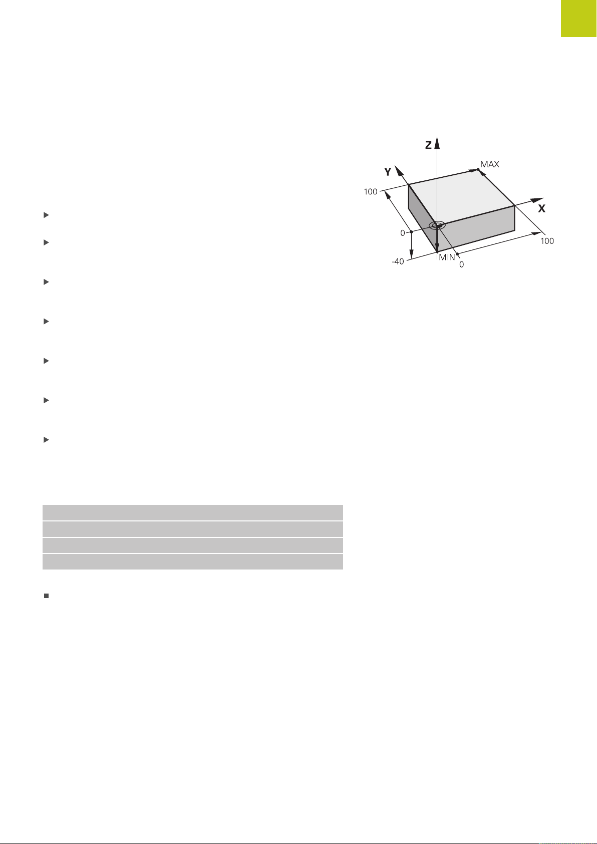
Programming the first part 1.3
Defining a workpiece blank
After you have created a new program you can define a workpiece
blank. For example, define a cuboid by entering the MIN and MAX
points, each with reference to the selected reference point.
After you have selected the desired blank form via soft key, the
TNC automatically initiates the workpiece blank definition and asks
for the required data:
Spindle axis Z – Plane XY: Enter the active spindle axis. G17 is
saved as default setting. Accept with the ENT key
Workpiece blank def.: Minimum X: Enter the smallest X
coordinate of the workpiece blank with respect to the reference
point, e.g. 0, confirm with the ENT key
Workpiece blank def.: Minimum Y: Smallest Y coordinate of
the workpiece blank with respect to the reference point, e.g. 0.
Confirm with the ENT key
Workpiece blank def.: Minimum Z: Smallest Z coordinate of
the workpiece blank with respect to the reference point, e.g.
-40, confirm with the ENT key
Workpiece blank def.: Maximum X: Enter the largest X
coordinate of the workpiece blank with respect to the reference
point, e.g. 100, confirm with the ENT key
Workpiece blank def.: Maximum Y: Enter the largest Y
coordinate of the workpiece blank with respect to the reference
point, e.g. 100. Confirm with the ENT key
Workpiece blank def.: Maximum Z: Enter the largest Z
coordinate of the workpiece blank with respect to the reference
point, e.g. 0. Confirm with the ENT key. The TNC concludes the
dialog
1
Example NC blocks
%NEW G71 *
N10 G30 G17 X+0 Y+0 Z-40 *
N20 G31 X+100 Y+100 Z+0 *
N99999999 %NEW G71 *
Further information on this topic
Defining the workpiece blank: page 103
TNC 640 | User's ManualDIN/ISO Programming | 1/2015
53
Page 54

1
First Steps with the TNC 640
1.3 Programming the first part
Program layout
NC programs should be arranged consistently in a similar manner.
This makes it easier to find your place, accelerates programming
and reduces errors.
Recommended program layout for simple, conventional
contour machining
1 Call tool, define tool axis
2 Retract the tool
3 Pre-position the tool in the working plane near the contour starting
point
4 In the tool axis, position the tool above the workpiece, or
preposition immediately to workpiece depth. If required, switch on
the spindle/coolant
5 Contour approach
6 Contour machining
7 Contour departure
8 Retract the tool, end program
Further information on this topic
Contour programming: see "Tool movements in the program"
Layout of contour machining
programs
%BSPCONT G71 *
N10 G30 G71 X... Y... Z... *
N20 G31 X... Y... Z... *
N30 T5 G17 S5000 *
N40 G00 G40 G90 Z+250 *
N50 X... Y... *
N60 G01 Z+10 F3000 M13 *
N70 X... Y... RL F500 *
...
N160 G40 ... X... Y... F3000 M9 *
N170 G00 Z+250 M2 *
N99999999 BSPCONT G71 *
Recommended program layout for simple cycle programs
1 Call tool, define tool axis
2 Retract the tool
3 Define the fixed cycle
4 Move to the machining position
5 Call the cycle, switch on the spindle/coolant
6 Retract the tool, end program
Further information on this topic
Cycle programming: See User’s Manual for Cycles
Cycle program layout
%BSBCYC G71 *
N10 G30 G71 X... Y... Z... *
N20 G31 X... Y... Z... *
N30 T5 G17 S5000 *
N40 G00 G40 G90 Z+250 *
N50 G200... *
N60 X... Y... *
N70 G79 M13 *
N80 G00 Z+250 M2 *
N99999999 BSBCYC G71 *
54
TNC 640 | User's ManualDIN/ISO Programming | 1/2015
Page 55

Programming a simple contour
The contour shown to the right is to be milled once to a depth of
5 mm. You have already defined the workpiece blank. After you
have initiated a dialog through a function key, enter all the data
requested by the TNC in the screen header.
Call the tool: Enter the tool data. Confirm each of
your entries with the ENT key, do not forget the
tool axis G17
Press the L key to open a program block for a
linear movement
Press the left arrow key to switch to the input
range for G codes
Press the G00 soft key if you want to enter a rapid
traverse motion
1
Programming the first part 1.3
Press the G90 soft key for absolute values
Retract tool: Press the orange axis key Z and enter
the value for the position to be approached, e.g.
250. Press the ENT key
Activate no radius compensation: Press the G40
soft key
Confirm Miscellaneous function M? with the END
key: The TNC saves the entered positioning block
Press the L key to open a program block for a
linear movement
Press the left arrow key to switch to the input
range for G codes
Press the G00 soft key if you want to enter a rapid
traverse motion
Preposition the tool in the working plane: Press
the orange X axis key and enter the value for the
position to be approached, e.g. –20
Press the orange axis key Y and enter the value for
the position to be approached, e.g. -20. Confirm
your entry with the ENT key.
Activate no radius compensation: Press the G40
soft key
Confirm Miscellaneous function M? with the END
key: The TNC saves the entered positioning block
Press the L key to open a program block for a
linear movement
Press the left arrow key to switch to the input
range for G codes
Press the G00 soft key if you want to enter a rapid
traverse motion
Move tool to working depth: Press the orange axis
key Z and enter the value for the position to be
approached, e.g. -5. Press the ENT key
TNC 640 | User's ManualDIN/ISO Programming | 1/2015
55
Page 56

1
First Steps with the TNC 640
1.3 Programming the first part
Activate no radius compensation: Press the G40
soft key
Miscellaneous function M? Switch on the spindle
and coolant, e.g. M13, confirm with the END key:
The TNC saves the entered positioning block
Press the L key to open a program block for a
linear movement
Enter the coordinates of the contour starting point
1 in X and Y, e.g. 5/5. Confirm with the ENT key
Activate radius compensation to the left of the
path: Press the G41 soft key
Feed rate F=? Enter the machining feed rate, e.g.
700 mm/min, save your entry with the END key
Enter 26 to approach the contour: Define for the
circular arc, save entries with the END key
Machine the contour and move to contour
point 2: You only need to enter the information
that changes. In other words, enter only the Y
coordinate 95 and save your entry with the END
key
Move to contour point 3: Enter the X coordinate 95
and save your entry with the END key
Define chamfer G24 on contour point 3: Enter
10 mm, save with the END key
Move to contour point 4: Enter the Y coordinate 5
and save your entry with the END key
Define chamfer G24 on contour point 4: Enter
20 mm, save with the END key
Move to contour point 1: Enter the X coordinate 5
and save your entry with the END key
Enter 27 to depart from the contour: Define the of
the departing arc
Depart contour: Enter coordinates outside of the
workpiece in X and Y, e.g. -20/-20, confirm with
the ENT key
Activate no radius compensation: Press the G40
soft key
Press the L key to open a program block for a
linear movement
Press the G00 soft key if you want to enter a rapid
traverse motion
Retract tool: Press the orange axis key Z to retract
in the tool axis, and enter the value for the position
to be approached, e.g. 250. Press the ENT key
Activate no radius compensation: Press the G40
soft key
MISCELLANEOUS FUNCTION M? Enter M2 to end
the program and confirm with the END key: The
TNC saves the entered positioning block
56
TNC 640 | User's ManualDIN/ISO Programming | 1/2015
Page 57

Further information on this topic
Complete example with NC blocks: see "Example: Linear
movements and chamfers with Cartesian coordinates",
page 229
Creating a new program: see "Opening programs and entering",
page 99
Approaching/departing contours: see "Approaching and
departing a contour"
Programming contours: see "Overview of path functions",
page 220
Tool radius compensation: see "Tool radius compensation ",
page 199
Miscellaneous functions (M): see "M functions for program run
inspection, spindle and coolant ", page 353
1
Programming the first part 1.3
TNC 640 | User's ManualDIN/ISO Programming | 1/2015
57
Page 58
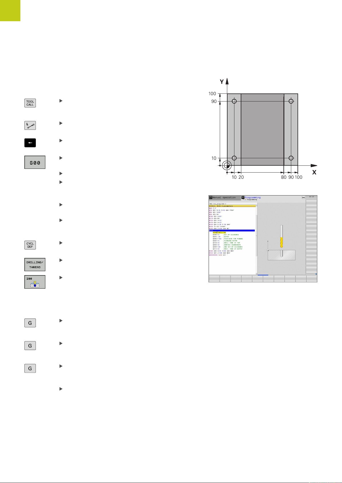
1
First Steps with the TNC 640
1.3 Programming the first part
Creating a cycle program
The holes (depth of 20 mm) shown in the figure at right are to be
drilled with a standard drilling cycle. You have already defined the
workpiece blank.
Call the tool: Enter the tool data. Confirm each of
your entries with the ENT key. Do not forget the
tool axis
Press the L key to open a program block for a
linear movement
Press the left arrow key to switch to the input
range for G codes
Press the G00 soft key if you want to enter a rapid
traverse motion
Press the G90 soft key for absolute values
Retract tool: Press the orange axis key Z and enter
the value for the position to be approached, e.g.
250. Press the ENT key
Activate no radius compensation: Press the G40
soft key
Miscellaneous function M? Switch on the spindle
and coolant, e.g. M13. Confirm with the END key:
The TNC saves the entered positioning block
Call the cycle menu
Display the drilling cycles
Select the standard drilling cycle 200: The TNC
starts the dialog for cycle definition. Enter all
parameters requested by the TNC step by step
and conclude each entry with the ENT key. In the
screen to the right, the TNC also displays a graphic
showing the respective cycle parameter
Enter 0 to approach the first drilling position: Enter
the coordinates of the drilling position, call the
cycle with M99
Enter 0 to move to further drilling positions: Enter
the coordinates of the specific drilling positions,
and call the cycle with M99
Enter 0 to retract the tool: Press the orange axis
key Z and enter the value for the position to be
approached, e.g. 250. Press the ENT key
Miscellaneous function M? Enter M2 to end the
program and confirm with the END key: The TNC
saves the entered positioning block
58
TNC 640 | User's ManualDIN/ISO Programming | 1/2015
Page 59

Example NC blocks
%C200 G71 *
N10 G30 G17 X+0 Y+0 Z-40 *
N20 G31 X+100 Y+100 Z+0 *
N30 T5 G17 S4500 *
N40 G00 G90 Z+250 G40 *
N50 G200
Q200=2 ;SET-UP CLEARANCE
Q201=-20 ;DEPTH
Q206=250 ;FEED RATE FOR PLNGNG
Q202=5 ;
Q210=0 ;DWELL TIME AT TOP
Q203=-10 ;SURFACE COORDINATE
Q204=20 ;2ND SET-UP CLEARANCE
Q211=0.2 ;DWELL TIME AT DEPTH
N60 G00 X+10 Y+10 M13 M99 *
N70 G00 X+10 Y+90 M99 *
N80 G00 X+90 Y+10 M99 *
N90 G00 X+90 Y+90 M99 *
N100 G00 Z+250 M2 *
N99999999 %C200 G71 *
1
Programming the first part 1.3
Definition of workpiece blank
Tool call
Retract the tool
Define the cycle
Spindle and coolant on, call the cycle
Call the cycle
Call the cycle
Call the cycle
Retract the tool, end program
Further information on this topic
Creating a new program: see "Opening programs and entering",
page 99
Cycle programming: See User’s Manual for Cycles, "Cycle
fundamentals / Overviews"
TNC 640 | User's ManualDIN/ISO Programming | 1/2015
59
Page 60
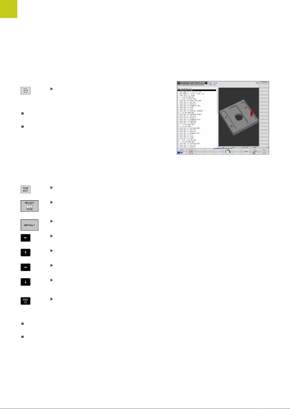
1
First Steps with the TNC 640
1.4 Graphically testing the first part
1.4 Graphically testing the first part
Selecting the correct operating mode
You can test programs in the Test Run mode:
Press the Test Run operating mode key: the TNC
switches to that mode
Further information on this topic
Operating modes of the TNC: see "Modes of Operation",
page 73
Testing programs: see "Test Run", page 560
Selecting the tool table for the test run
You only need to execute this step if you have not activated a tool
table in the Test Run mode.
Press the PGM MGT key: The TNC opens the file
manager
Press the SELECT TYPE soft key: The TNC shows
a soft-key menu for selection of the file type to be
displayed
Press the DEFAULT soft key: The TNC shows all
saved files in the right window
Move the highlight to the left onto the directories
Move the highlight to the TNC:\table directory
Move the highlight to the right onto the files
Move the highlight to the file TOOL.T (active tool
table) and load with the ENT key: TOOL.T receives
the status S and is therefore active for the test run
Press the END key: Exit the file manager
Further information on this topic
Tool management: see "Enter tool data into the table",
page 172
Testing programs: see "Test Run", page 560
60
TNC 640 | User's ManualDIN/ISO Programming | 1/2015
Page 61
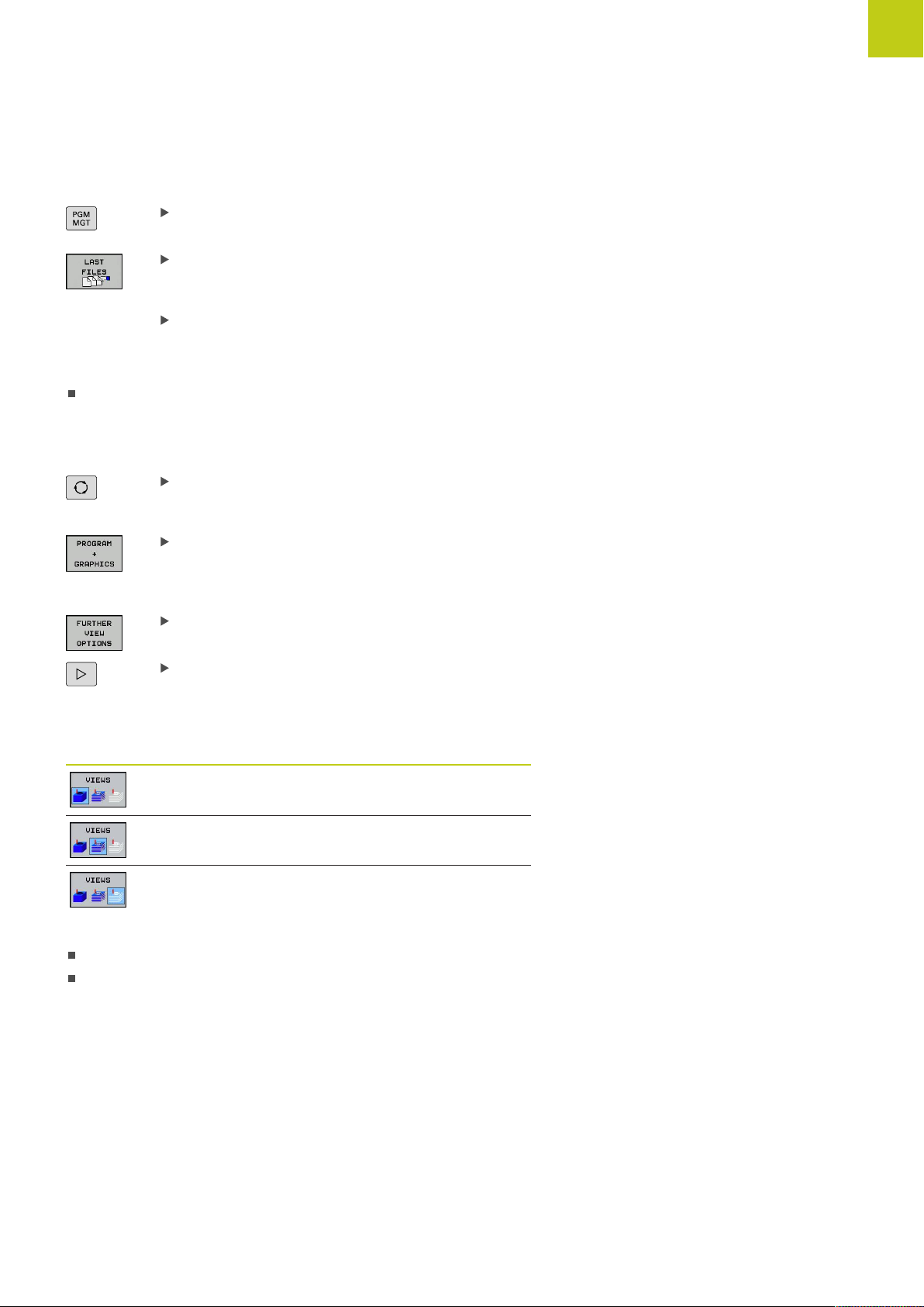
Choosing the program you want to test
Press the PGM MGT key: The TNC opens the file
manager
Press the LAST FILES soft key: The TNC opens a
pop-up window with the most recently selected
files
Use the arrow keys to select the program that you
want to test. Load with the ENT key
Further information on this topic
Selecting a program: see "Working with the File Manager",
page 114
Selecting the screen layout and the view
Press the key for selecting the screen layout. The
TNC shows all available alternatives in the soft-key
row
Press the PROGRAM + GRAPHICS soft key: In
the left half of the screen the TNC shows the
program; in the right half it shows the workpiece
blank
Press the FURTHER VIEW OPTIONS soft key
1
Graphically testing the first part 1.4
Shift the soft-key row and select the desired view
by soft key
The TNC features the following views:
Soft keys Function
Volume view
Volume view and tool paths
Tool paths
Further information on this topic
Graphic functions: see "Graphics ", page 548
Running a test run: see "Test Run", page 560
TNC 640 | User's ManualDIN/ISO Programming | 1/2015
61
Page 62

1
First Steps with the TNC 640
1.4 Graphically testing the first part
Starting the test run
Press the RESET + START soft key: The TNC
simulates the active program up to a programmed
break or to the program end
While the simulation is running, you can use the
soft keys to change views
Press the STOP soft key: The TNC interrupts the
test run
Press the START soft key: The TNC resumes the
test run after a break
Further information on this topic
Running a test run: see "Test Run", page 560
Graphic functions: see "Graphics ", page 548
Adjust the simulation speed: see "Speed of the Setting test
runs", page 549
62
TNC 640 | User's ManualDIN/ISO Programming | 1/2015
Page 63
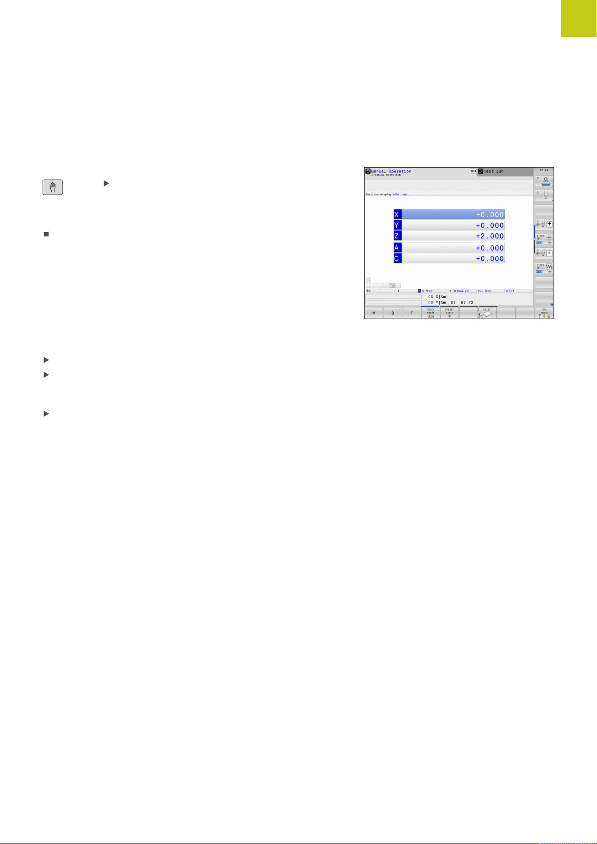
1.5 Setting up tools
Selecting the correct operating mode
Tools are set up in the Manual Operation mode:
Press the operating-mode key: The TNC switches
to the Manual mode of operation
Further information on this topic
Operating modes of the TNC: see "Modes of Operation",
page 73
1
Setting up tools 1.5
Preparing and measuring tools
Clamp the required tools in their tool holders
When measuring with an external tool presetter: Measure the
tools, note down the length and radius, or transfer them directly
to the machine through a transfer program
When measuring on the machine: store the tools in the tool
changer, see page 65
TNC 640 | User's ManualDIN/ISO Programming | 1/2015
63
Page 64

1
First Steps with the TNC 640
1.5 Setting up tools
The tool table TOOL.T
In the tool table TOOL.T (permanently saved under TNC:\table\),
save the tool data such as length and radius, but also further toolspecific information that the TNC needs to perform its functions.
To enter tool data in the tool table TOOL.T, proceed as follows:
Display the tool table: The TNC shows the tool
table
Edit the tool table: Set the EDITING soft key to ON
With the upward or downward arrow keys you can
select the tool number that you want to edit
With the rightward or leftward arrow keys you can
select the tool data that you want to edit
To exit the tool table, press the END key
Further information on this topic
Operating modes of the TNC: see "Modes of Operation",
page 73
Working with the tool table: see "Enter tool data into the table",
page 172
64
TNC 640 | User's ManualDIN/ISO Programming | 1/2015
Page 65
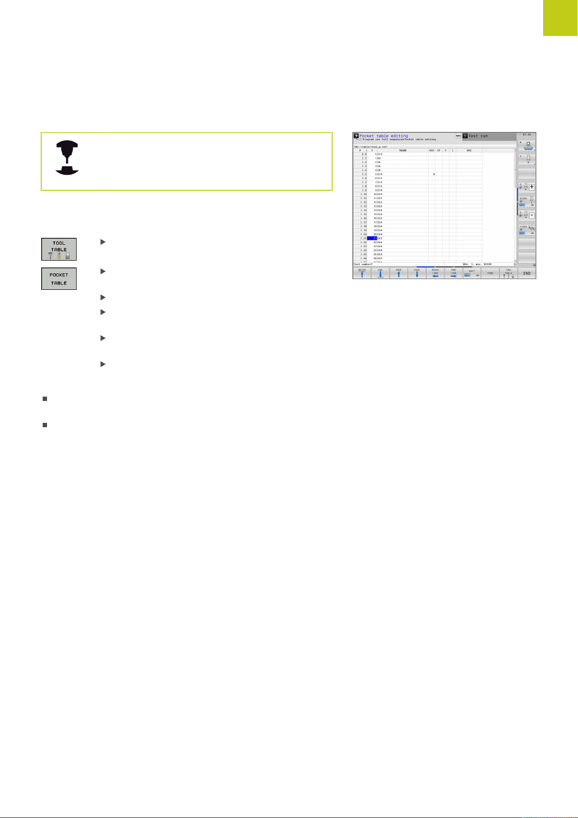
The pocket table TOOL_P.TCH
The function of the pocket table depends on the
machine. Refer to your machine manual.
In the pocket table TOOL_P.TCH (permanently saved under TNC:
\TABLE\) you specify which tools your tool magazine contains.
To enter data in the pocket table TOOL_P.TCH, proceed as follows:
Display the tool table: The TNC shows the tool
table
Display the pocket table: The TNC shows the
pocket table
Edit the pocket table: Set the EDIT soft key to ON
With the upward or downward arrow keys you can
select the pocket number that you want to edit
With the rightward or leftward arrow keys you can
select the data that you want to edit
Exit the pocket table: press the END key.
1
Setting up tools 1.5
Further information on this topic
Operating modes of the TNC: see "Modes of Operation",
page 73
Working with the pocket table: see "Pocket table for tool
changer", page 181
TNC 640 | User's ManualDIN/ISO Programming | 1/2015
65
Page 66

1
First Steps with the TNC 640
1.6 Workpiece setup
1.6 Workpiece setup
Selecting the correct operating mode
Workpieces are set up in the or mode
Press the operating-mode key: The TNC switches
to the Manual mode of operation
Further information on this topic
Operating mode : see "Moving the machine axes", page 483
Clamping the workpiece
Mount the workpiece with a fixture on the machine table. If you
have a 3-D touch probe on your machine, then you do not need to
clamp the workpiece parallel to the axes.
If you do not have a 3-D touch probe available, you have to align the
workpiece so that it is fixed with its edges parallel to the machine
axes.
Further information on this topic
Setting datums with 3-D touch probe: see "Datum setting with
3-D touch probe ", page 527
Setting datums without 3-D touch probe: see "Datum setting
without a 3-D touch probe", page 507
66
TNC 640 | User's ManualDIN/ISO Programming | 1/2015
Page 67

Datum setting with 3-D touch probe
Insert a 3-D touch probe: In the Positioning with Manual Data
Input mode, run a TOOLCALL block containing the tool axis and
then return to the Manual Operation mode
Select the probing functions: The TNC displays the
available functions in the soft-key row
Set the datum at a workpiece corner, for example
Position the touch probe near the first touch point
on the first workpiece edge
Select the probing direction via soft key
Press NC start: The touch probe moves in the
defined direction until it contacts the workpiece
and then automatically returns to its starting point
Use the axis-direction keys to pre-position the
touch probe to a position near the second touch
point on the first workpiece edge
Press NC start: The touch probe moves in the
defined direction until it contacts the workpiece
and then automatically returns to its starting point
Use the axis-direction keys to pre-position the
touch probe to a position near the first touch point
on the second workpiece edge
Select the probing direction via soft key
Press NC start: The touch probe moves in the
defined direction until it contacts the workpiece
and then automatically returns to its starting point
Use the axis-direction keys to pre-position the
touch probe to a position near the second touch
point on the second workpiece edge
Press NC start: The touch probe moves in the
defined direction until it contacts the workpiece
and then automatically returns to its starting point
Then the TNC shows the coordinates of the
measured corner point
To set to 0: Press the SET DATUM soft key
Press the END soft key to close the menu
1
Workpiece setup 1.6
Further information on this topic
Datum setting: see "Datum setting with 3-D touch probe ",
page 527
TNC 640 | User's ManualDIN/ISO Programming | 1/2015
67
Page 68
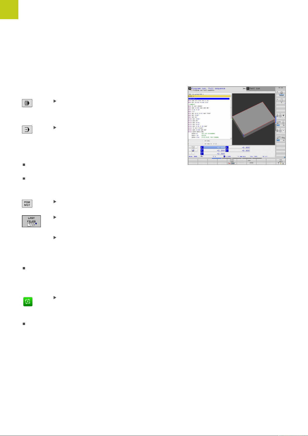
1
First Steps with the TNC 640
1.7 Running the first program
1.7 Running the first program
Selecting the correct operating mode
You can run programs either in the Single Block or the Full
Sequence mode:
Press the operating mode key: The TNC goes into
the Program Run, Single Block mode and the
TNC executes the program block by block. You
have to confirm each block with the NC start key
Press the Program Run, Full Sequence operating
mode key: The TNC switches to that mode and
runs the program after NC start up to a program
interruption or to the end of the program
Further information on this topic
Operating modes of the TNC: see "Modes of Operation",
page 73
Running programs: see "Program run", page 562
Choosing the program you want to run
Press the PGM MGT key: The TNC opens the file
manager
Press the LAST FILES soft key: The TNC opens a
pop-up window with the most recently selected
files
If desired, use the arrow keys to select the
program that you want to run. Load with the ENT
key
Further information on this topic
File Management: see "Working with the File Manager",
page 114
Start the program
Press the NC start key: The TNC runs the active
program
Further information on this topic
Running programs: see "Program run", page 562
68
TNC 640 | User's ManualDIN/ISO Programming | 1/2015
Page 69

2
Introduction
Page 70

2
Introduction
2.1 The TNC 640
2.1 The TNC 640
HEIDENHAIN TNC controls are workshop-oriented contouring
controls that enable you to program conventional milling and drilling
operations right at the machine in an easy-to-use conversational
programming language. They are designed for milling, drilling and
boring machines, as well as machining centers, with up to 18 axes.
You can also change the angular position of the spindle under
program control.
An integrated hard disk provides storage for as many programs as
you like, even if they were created off-line. For quick calculations
you can call up the on-screen pocket calculator at any time.
Keyboard and screen layout are clearly arranged in such a way that
the functions are fast and easy to use.
Programming: In HEIDENHAIN conversational and DIN/ISO
The HEIDENHAIN conversational programming format is an
especially easy method of writing programs. Interactive graphics
illustrate the individual machining steps for programming the
contour. If a production drawing is not dimensioned for NC, the
FK free contour programming feature performs the necessary
calculations automatically. Workpiece machining can be graphically
simulated either during or before actual machining.
It is also possible to program in ISO format or DNC mode.
You can also enter and test one program while the control is
running another.
Compatibility
Machining programs created on HEIDENHAIN contouring controls
(starting from the TNC 150 B) may not always run on the TNC 640.
If NC blocks contain invalid elements, the TNC will mark them as
ERROR blocks or with error messages when the file is opened.
Please also note the detailed description of the
differences between the iTNC 530 and the TNC 640,
see "Functions of the TNC 640 and the iTNC 530
compared", page 635.
70
TNC 640 | User's ManualDIN/ISO Programming | 1/2015
Page 71

1
7
7
2
5
4
3
4
6
8
Visual display unit and operating panel 2.2
2.2 Visual display unit and operating
panel
Display screen
The TNC is shipped with a 19-inch TFT flat-panel display.
1 Header
When the TNC is on, the selected operating modes are shown
in the screen header: the machining mode at the left and the
programming mode at right. The currently active operating
mode is displayed in the larger box, where the dialog prompts
and TNC messages also appear (unless the TNC is showing
only graphics).
2 Soft keys
In the footer the TNC indicates additional functions in a softkey row. You can select these functions by pressing the keys
immediately below them. The thin bars immediately above the
soft-key row indicate the number of soft-key rows that can be
called with the keys to the right and left that are used to switch
the soft keys. The bar representing the active soft-key row is
highlighted
3 Soft-key selection keys
4 Keys for switching the soft keys
5 Setting the screen layout
6 Shift key for switchover between machining and programming
modes
7 Soft-key selection keys for machine tool builders
8 Keys for switching the soft keys for machine tool builders
2
Setting the screen layout
You select the screen layout yourself: In the Programming
mode of operation, for example, you can have the TNC show
program blocks in the left window while the right window displays
programming graphics. You could also display the program
structure in the right window instead, or display only program
blocks in one large window. The available screen windows depend
on the selected operating mode.
To change the screen layout:
Press the screen layout key: The soft-key row
shows the available layout options, see "Modes of
Operation"
Select the desired screen layout
TNC 640 | User's ManualDIN/ISO Programming | 1/2015
71
Page 72

2
2
3
4
5
8
9
6
7
10
1
Introduction
2.2 Visual display unit and operating panel
Control Panel
The TNC 640 is delivered with an integrated keyboard. The figure to
the right shows the operating elements of the operating panel:
1 Alpha-numeric keyboard for entering texts and file names, as
well as for DIN/ISO programming
2
3 Programming modes
4 Machine operating modes
5 Initiating programming dialogs
6
7 Numerical input and axis selection
8 Touchpad
9 Mouse buttons
10 USB connection
File management
Calculator
MOD function
HELP function
Navigation keys and GOTO jump command
The functions of the individual keys are described on the inside
front cover.
Some machine manufacturers do not use the
standard operating panel from HEIDENHAIN. Refer
to your machine manual.
External buttons, e.g. NC START or NC STOP, are
described in the manual for your machine tool.
72
TNC 640 | User's ManualDIN/ISO Programming | 1/2015
Page 73

2.3 Modes of Operation
Manual Operation and El. Handwheel
The Manual Operation mode is required for setting up the machine
tool. In this mode of operation, you can position the machine axes
manually or by increments, set the datums and tilt the working
plane.
The El. Handwheel mode of operation allows you to move the
machine axes manually with the HR electronic handwheel.
Soft keys for selecting the screen layout (select as described
previously)
Soft key Window
Positions
2
Modes of Operation 2.3
Left: positions, right: status display
Left: positions, right: collision object
Positioning with Manual Data Input
This mode of operation is used for programming simple traversing
movements, such as for face milling or prepositioning.
Soft keys for selecting the screen layout
Soft key Window
Program
Left: program, right: status display
Left: program, right: collision object
TNC 640 | User's ManualDIN/ISO Programming | 1/2015
73
Page 74
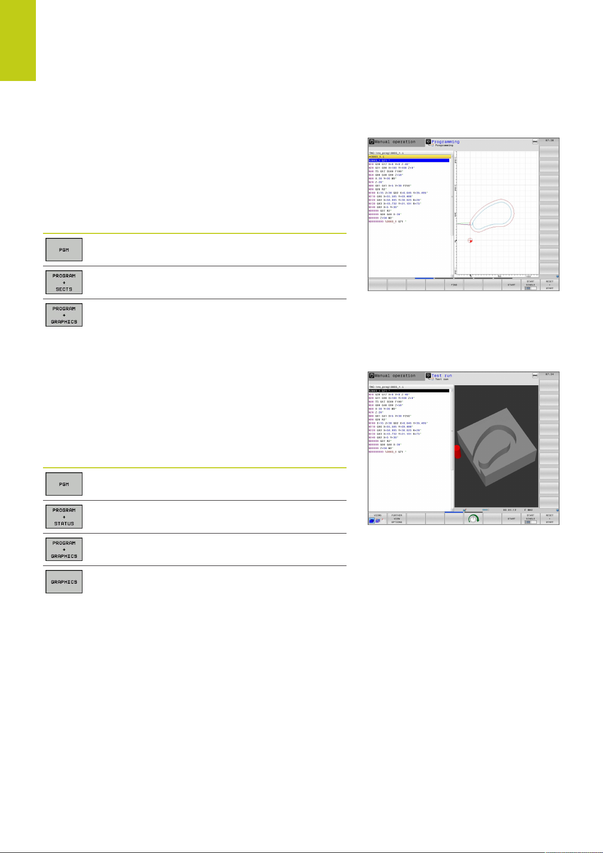
2
Introduction
2.3 Modes of Operation
Programming
In this mode of operation you can write your part programs.
The FK free programming feature, the various cycles and the
Q parameter functions help you with programming and add
necessary information. If desired, you can have the programming
graphics show the programmed paths of traverse.
Soft keys for selecting the screen layout
Soft key Window
Program
Left: program, right: program structure
Left: program, right: programming graphics
Test Run
In the Test Run mode of operation, the TNC checks programs and
program sections for errors, such as geometrical incompatibilities,
missing or incorrect data within the program or violations of the
working space. This simulation is supported graphically in different
display modes.
Soft keys for selecting the screen layout
Soft key Window
Program
Left: program, right: status display
Left: program, right: graphics
Graphic
74
TNC 640 | User's ManualDIN/ISO Programming | 1/2015
Page 75

Program Run, Full Sequence and Program Run, Single Block
In the Program run full sequence mode of operation the TNC
executes a program continuously to its end or to a manual
or programmed stop. You can resume program run after an
interruption.
In the Program run single block mode of operation you execute
each block separately by pressing the machine START button. With
point pattern cycles and CYCL CALL PAT, the control stops after
each point.
Soft keys for selecting the screen layout
Soft key Window
Program
2
Modes of Operation 2.3
Left: program, right: status display
Left: program, right: graphics
Graphic
Left: program, right: collision object
Collision body
Soft key Window
Pallet table
Left: program, right: pallet table
Left: pallet table, right: status display
Left: pallet table, right: graphics
TNC 640 | User's ManualDIN/ISO Programming | 1/2015
75
Page 76
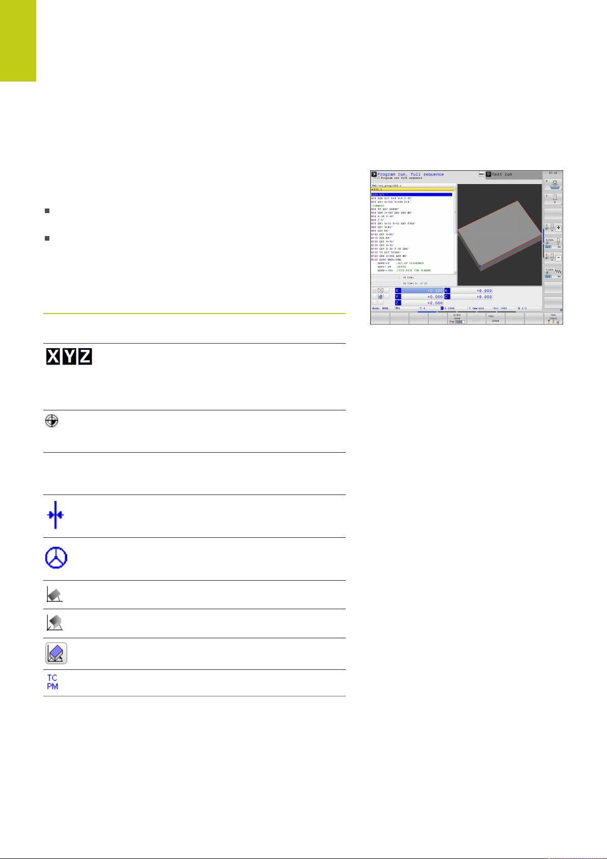
2
Introduction
2.4 Status displays
2.4 Status displays
General status display
The general status display in the lower part of the screen informs
you of the current state of the machine tool. It is displayed
automatically in the following modes of operation:
Program Run, Single Block and Program Run, Full Sequence,
except if the screen layout is set to display only, and during
Positioning with Manual Data Input.
In the Manual Operation and El. Handwheel modes the status
display appears in the large window.
Information in the status display
Icon Meaning
ACTL. Position display: Actual, nominal or distance-to-go
coordinates mode
Machine axes; the TNC displays auxiliary axes in
lower-case letters. The sequence and quantity of
displayed axes is determined by the machine tool
builder. Refer to your machine manual for more
information
Number of the active presets from the preset
table. If the datum was set manually, the TNC
displays the text MAN behind the symbol
F S M The displayed feed rate in inches corresponds to
one tenth of the effective value. Spindle speed S,
feed rate F and active M functions
Axis is clamped
Axis can be moved with the handwheel
Axes are moving under a basic rotation
Axes are moving under a 3-D basic rotation
Axes are moving in a tilted working plane
76
The M128 is active
TNC 640 | User's ManualDIN/ISO Programming | 1/2015
Page 77

Icon Meaning
No active program
Program run has started
Program run is stopped
Program run is being aborted
Turning mode is active
The Dynamic Collision Monitoring function (DCM)
is active (Option #40)
2
Status displays 2.4
The Adaptive Feed Function (AFC) is active
(Option #45)
The Active Chatter Control feature (ACC) is active
(Option #145)
The CTC function is active (Option #141)
Additional status displays
The additional status displays contain detailed information on the
program run. They can be called in all operating modes except for
the Programming mode of operation.
To switch on the additional status display
Call the soft-key row for screen layout
Select the screen layout with additional status
display: In the right half of the screen, the TNC
shows the OVERVIEW status form
To select an additional status display
Switch the soft-key rows until the STATUS soft
keys appear
Either select the additional status display directly
by soft key, e.g. positions and coordinates, or
use the switch-over soft keys to select the desired
view
The available status displays described below can be selected
either directly by soft key or with the switch-over soft keys.
Please note that some of the status information
described below is not available unless the
associated software option is enabled on your TNC.
TNC 640 | User's ManualDIN/ISO Programming | 1/2015
77
Page 78
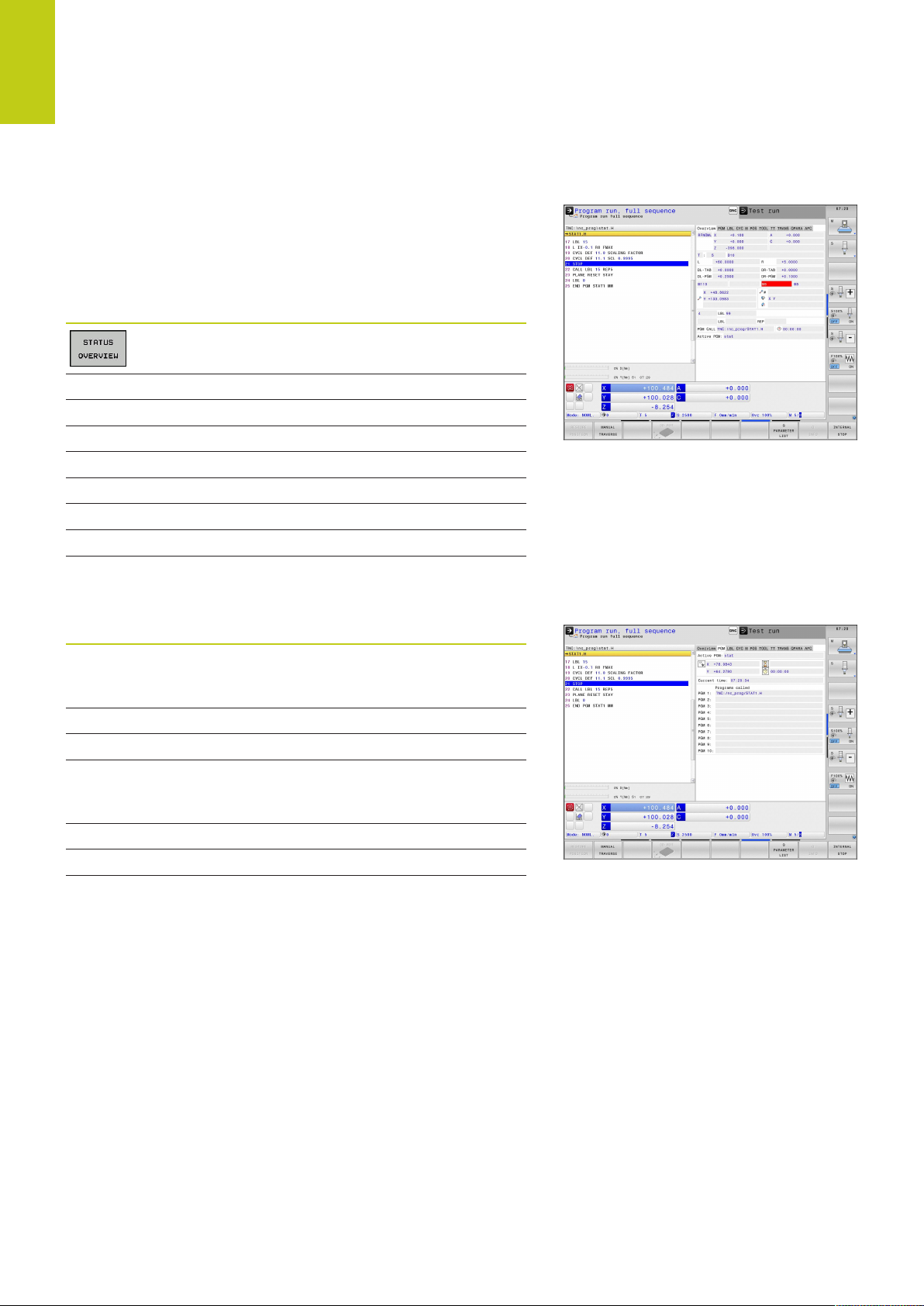
2
Introduction
2.4 Status displays
Overview
After switch-on, the TNC displays the Overview status form,
provided that you have selected the PROGRAM+STATUS screen
layout (or POSITION + STATUS). The overview form contains a
summary of the most important status information, which you can
also find on the various detail forms.
Soft key Meaning
Position display
Tool information
Active M functions
Active coordinate transformations
Active subprogram
Active program section repeat
Program called with PGM CALL
Current machining time
Name of the active main program
General program information (PGM tab)
Soft key Meaning
No direct
selection
possible
Name of the active main program
Circle center CC (pole)
Dwell time counter
Machining time when the program was
completely simulated in the Test Run operating
mode
Current machining time in percent
Current time
Active programs
78
TNC 640 | User's ManualDIN/ISO Programming | 1/2015
Page 79
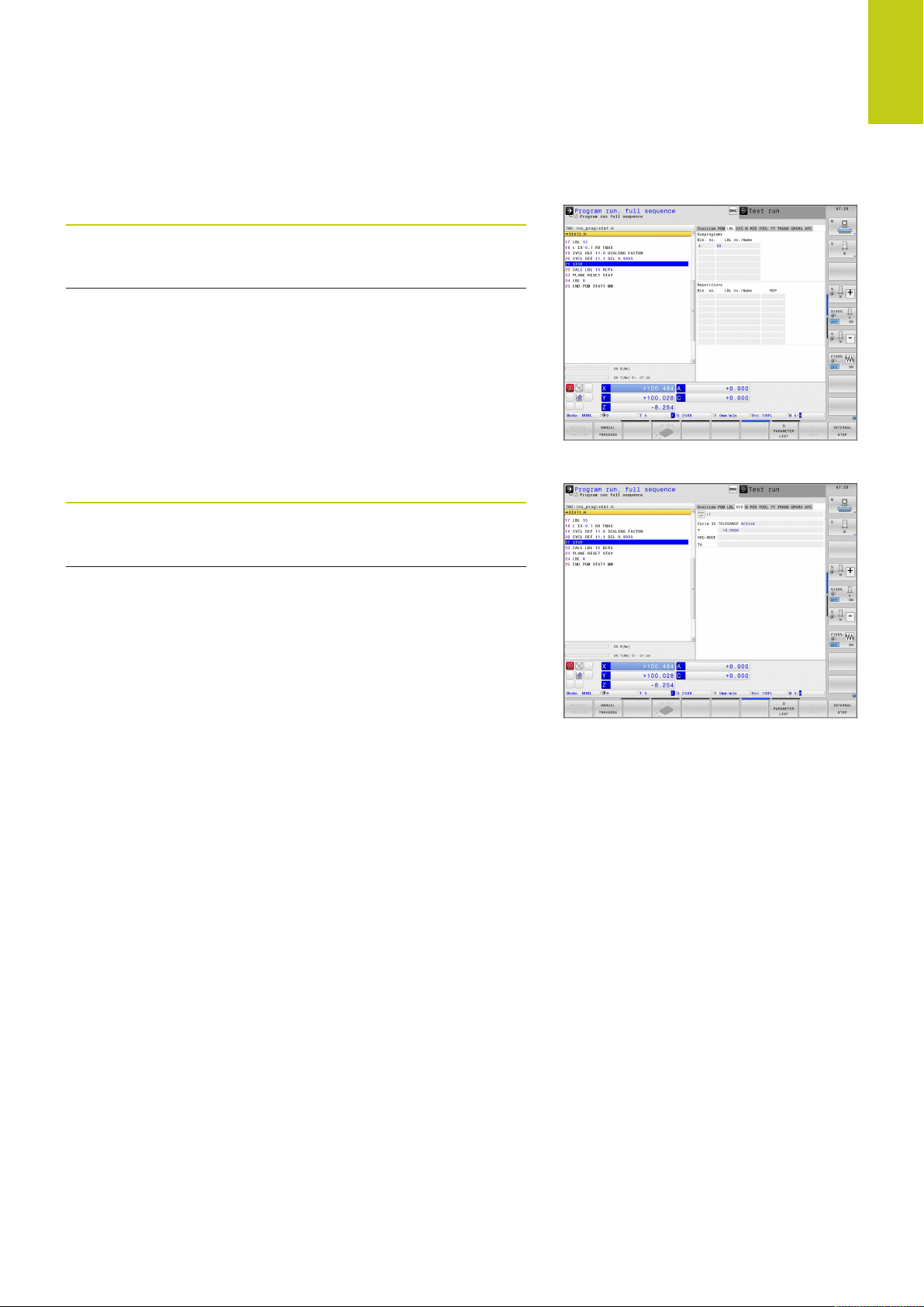
Program section repeat/Subprograms (LBL tab)
Soft key Meaning
2
Status displays 2.4
No direct
selection
possible
Information on standard cycles (CYC tab)
Soft key Meaning
No direct
selection
possible
Active program section repeats with block
number, label number, and number of
programmed repeats/repeats yet to be run
Active subprograms with block number in
which the subprogram was called and the label
number that was called
Active fixed cycle
Active values of Cycle 32 Tolerance
TNC 640 | User's ManualDIN/ISO Programming | 1/2015
79
Page 80

2
Introduction
2.4 Status displays
Active miscellaneous functions M (M tab)
Soft key Meaning
No direct
selection
possible
Positions and coordinates (POS tab)
Soft key Meaning
List of the active M functions with fixed
meaning
List of the active M functions that are adapted
by your machine manufacturer
Type of position display, e.g. actual position
Tilt angle of the working plane
Angle of a basic rotation
Active kinematics
80
TNC 640 | User's ManualDIN/ISO Programming | 1/2015
Page 81

Information on tools (TOOL tab)
Soft key Meaning
Display of active tool:
T: Tool number and tool name
RT: Number and name of a replacement tool
Tool axis
Tool length and tool radii
Oversizes (delta values) from the tool table (TAB)
and the TOOL CALL (PGM)
Tool life, maximum tool life (TIME 1) and maximum
tool life for TOOL CALL (TIME 2)
Display of programmed tool and replacement tool
2
Status displays 2.4
Tool measurement (TT tab)
The TNC displays the TT tab only if the function is
active on your machine.
Soft key Meaning
No direct
selection
possible
Number of the tool to be measured
Display whether the tool radius or the tool
length is being measured
MIN and MAX values of the individual cutting
edges and the result of measuring the rotating
tool (DYN = dynamic measurement)
Cutting edge number with the corresponding
measured value. If the measured value is
followed by an asterisk, the tolerance in the
tool table was exceeded
TNC 640 | User's ManualDIN/ISO Programming | 1/2015
81
Page 82
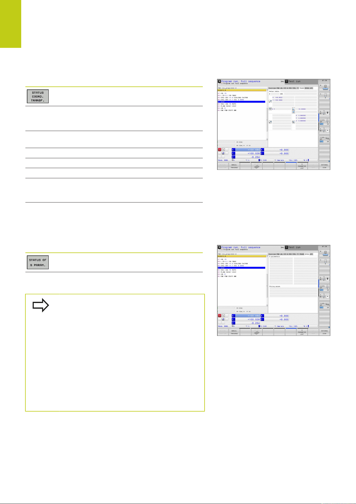
2
Introduction
2.4 Status displays
Coordinate transformations (TRANS tab)
Soft key Meaning
Name of the active datum table
Active datum number (#), comment from the
active line of the active datum number (DOC)
from Cycle G53
Active datum shift (Cycle G54); The TNC
displays an active datum shift in up to 8 axes
Mirrored axes (Cycle G28)
Active basic rotation
Active rotation angle (Cycle G73)
Active scaling factor/factors (Cycles G72); The
TNC displays an active scaling factor in up to 6
axes
Scaling datum
For further information, refer to the User's Manual for Cycles,
"Coordinate Transformation Cycles."
Displaying Q parameters (QPARA tab)
Soft key Meaning
Display the current values of the defined Q
parameters
Display the character strings of the defined
string parameters
Press the Q PARAMETER LIST soft key. The TNC
opens a pop-up window. For each parameter type
(Q, QL, QR, QS), define the parameter numbers you
wish to control. Separate single Q parameters with
a comma, and connect sequential Q parameters
with a hyphen, e.g. 1,3,200-208. The input range per
parameter type is 132 characters.
The display in the QPARA tab always contains eight
decimal places. The result of Q1 = COS 89.999 is
shown by the control as 0.00001745 for example.
Very large or very small values are displayed by
the control in exponential notation. The result of
Q1 = COS 89.999 * 0.001 is shown by the control as
+1.74532925e-08, whereby e-08 corresponds to the
factor of 10-8.
82
TNC 640 | User's ManualDIN/ISO Programming | 1/2015
Page 83

Adaptive Feed Control (AFC tab, Option #45)
The TNC displays the AFC tab only if the function is
active on your machine.
Soft key Meaning
2
Status displays 2.4
No direct
selection
possible
Active tool (number and name)
Cut number
Current factor of the feed potentiomenter in
percent
Active spindle load in percent
Reference load of the spindle
Current spindle speed
Current deviation of the speed
Current machining time
Line diagram, in which the current spindle load
and the value commanded by the TNC for the
feed-rate override are shown
TNC 640 | User's ManualDIN/ISO Programming | 1/2015
83
Page 84

2
Introduction
2.5 Window Manager
2.5 Window Manager
The machine tool builder determines the available
functions and behavior of the window manager.
Refer to your machine manual.
The TNC features the Xfce window manager. Xfce is a standard
application for UNIX-based operating systems, and is used to
manage graphical user interfaces. The following functions are
possible with the window manager:
Display a task bar for switching between various applications
(user interfaces).
Manage an additional desktop, on which special applications
from your machine tool builder can run.
Control the focus between NC-software applications and those
of the machine tool builder.
The size and position of pop-up windows can be changed.
It is also possible to close, minimize and restore the pop-up
windows.
The TNC shows a star in the upper left of the screen
if an application of the window manager or the
window manager itself has caused an error In this
case, switch to the window manager and correct the
problem. If required, refer to your machine manual.
84
TNC 640 | User's ManualDIN/ISO Programming | 1/2015
Page 85

Task bar
In the task bar you can choose different workspaces by mouse
click. The TNC provides the following workspaces:
Workspace 1: Active mode of operation
Workspace 2: Active programming mode
Workspace 3: Manufacturer's applications (optionally available)
In the task bar you can also select other applications that you have
started together with the TNC (switch for example to the PDF
viewer or TNCguide)
Click the green HEIDENHAIN symbol to open a menu in which
you can get information, make settings or start applications. The
following functions are available:
About HEROS: Information about the operating system of the
TNC
NC Control: Start and stop the TNC software. Only permitted
for diagnostic purposes
Web Browser: Start Mozilla Firefox
Remote Desktop Manager (Option #133): Display and remote
operation of external computer units
Diagnostics: Available only to authorized specialists to start
diagnostic functions
Settings: Configuration of miscellaneous settings
Date/Time: Set the date and time
Language: System dialog language setting. During startup
the TNC overwrites this setting with the language setting of
the machine parameter CfgLanguage
Network: Network settings of the control
Screensaver: Screensaver settings
SELinux: Security software settings for Linux-based
operating systems
Shares: Settings for external network drives
VNC: Setting for external softwares that access for
maintenance purposes on the control for example (Virtual
Network Computing)
WindowManagerConfig: Available only to authorized
specialists for setting the window manager
Firewall: Firewall settings see "Firewall", page 600
Tools: Only for authorized users. The applications available under
tools can be started directly by selecting the pertaining file type
in the file management of the TNC (see "File Management:
Fundamentals", page 111)
2
Window Manager 2.5
TNC 640 | User's ManualDIN/ISO Programming | 1/2015
85
Page 86
2
Introduction
2.6 Remote Desktop Manager (Option #133)
2.6 Remote Desktop Manager
(Option #133)
Introduction
The Remote Desktop Manager enables you to display external
computer units on the TNC screen that are connected via Ethernet
and to operate them over the TNC. You can also start programs
specifically under HeROS or display web pages of an external
server.
The following connection options are available:
Windows Terminal Server (RDP): Displays the desktop of a
remote Windows computer on the control
Windows Terminal Server (RemoteFX): Displays the desktop
of a remote Windows computer on the control
VNC: Connection to an external computer (e.g. HEIDENHAINIPC). Displays the desktop of a remote Windows or Unix
computer on the control
Switch-off/restart of a computer: Available only to authorized
specialists
World Wide Web: Available only to authorized specialists
SSH: Available only to authorized specialists
XDMCP: Available only to authorized specialists
User-defined connection: Available only to authorized
specialists
HEIDENHAIN assures a functioning connection
between HeROS 5 and the IPC 6341. HEIDENHAIN
cannot guarantee the correct function of any other
combinations or connections to external devices.
Configuring connections – Windows Terminal Service
Configuring an external computer
You do not need additional software for your external
computer for connecting to the Windows Terminal
Service.
Proceed as follows to configure the external computer, e.g. in the
Windows 7 operating system:
After pressing the Windows start button select the menu item
System control via the task bar
Select the System menu item
Select the Advanced system settings menu item
Select the Remote tab
86
TNC 640 | User's ManualDIN/ISO Programming | 1/2015
Page 87

Remote Desktop Manager (Option #133) 2.6
In the Remote support area, activate the function Permit
remote support connection with this computer
In the Remote desktop area, activate the function Permit
connections from computers on which any version of
remote desktop is installed
Confirm the settings via the OK button
Configuring the TNC
Depending on the operating system of your external
computer and the protocol used in accordance with
this, select either Windows Terminal Service (RDP)
or Windows Terminal Service (RemoteFX).
Configure the TNC as follows:
After pressing the green HEIDENHAIN button, select the menu
item Remote Desktop Manager via the task bar
Press the New connection button in the
Remote Desktop Manager window
Select the menu item Windows Terminal Service (RDP) or
Windows Terminal Service (RemoteFX)
Specify the required connection information in the
Edit connection window
2
Setting Meaning Input
Connection name
Restarting after end of
connection
Automatic starting upon
login
Add to favorites
Move to the following
workspace
Release USB mass memory
Name of the connection in the Remote Desktop Manager Required
Behavior with terminated connection:
Always restart
Never restart
Always after an error
Ask after an error
Connection automatically established during control power-up Required
Connection icon in the task bar:
Double click with left mouse button: The control starts the
connection
Single click with left mouse button: The control changes to the
desktop of the connection
Single click with right mouse button: The control displays the
connection menu
Number of desktop for the connection, whereby desktops 0 and 1
are reserved for the NC software
Enable access to connected USB mass memory Required
Required
Required
Required
Computer
User name
Password
Windows domain
Full screen mode or user-
defined window size
TNC 640 | User's ManualDIN/ISO Programming | 1/2015
Host name or IP address of the external computer Required
Name of the user Required
User password Required
Domain of the external computer Required
Size of the connection window Required
87
Page 88

2
Introduction
2.6 Remote Desktop Manager (Option #133)
Setting Meaning Input
Entries in the Advanced
options area
Available only to authorized specialists Optional
Configuring the connection – VNC
Configuring an external computer
You do not need an additional VNC server for your
external computer for connecting to VNC.
Install and configure the VNC server, e.g. the
TightVNC server, before configuring the TNC.
Configuring the TNC
Configure the TNC as follows:
Select the Remote Desktop Manager menu item via the task
bar
Press the New connection button in the
Remote Desktop Manager window
Select the VNC menu item
Specify the required connection information in the
Edit connection window
Setting Meaning Input
Connection name
Restarting after end of
connection
Automatic starting upon
login
Add to favorites
Move to the following
workspace
Release USB mass memory
Computer
Name of the connection in the Remote Desktop Manager Required
Behavior with terminated connection:
Always restart
Never restart
Always after an error
Ask after an error
Connection automatically established during control power-up Required
Connection icon in the task bar:
Double click with left mouse button: The control starts the
connection
Single click with left mouse button: The control changes to the
desktop of the connection
Single click with right mouse button: The control displays the
connection menu
Number of desktop for the connection, whereby desktops 0 and 1
are reserved for the NC software
Permit access to connected USB mass memory Required
Host name or IP address of the external computer Required
Required
Required
Required
Password
Full screen mode or user-
defined window size
Permit further connections
(share)
88
Password for connecting to the VNC server Required
Size of the connection window Required
Enable access to the VNC server also by other VNC connections Required
TNC 640 | User's ManualDIN/ISO Programming | 1/2015
Page 89

Remote Desktop Manager (Option #133) 2.6
Setting Meaning Input
2
View only
Entries in the Advanced
options area
The external computer cannot be operated in display mode Required
Available only to authorized specialists Optional
Starting and stopping the connection
Once a connection has been configured, it is shown as an icon in
the Remote Desktop Manager window. Click the connection icon
with the right mouse key to open a menu in which the display can
be started and stopped.
Use the right DIADUR key on the keyboard to change to Desktop 3
and back to the TNC interface. You can also use the task bar to get
to this desktop.
If the desktop of the external connection or the external computer
is active, all inputs from the mouse and the keyboard are
transmitted there.
All connections are canceled automatically when the HEROS 5
operating system is shut down. Please note, however, that only
the connection is canceled, whereas the external computer or the
external system is not shut down automatically.
TNC 640 | User's ManualDIN/ISO Programming | 1/2015
89
Page 90

2
Introduction
2.7 SELinux security software
2.7 SELinux security software
SELinux is an extension for Linux-based operating systems.
SELinux is an additional security software package based on
Mandatory Access Control (MAC) and protects the system against
the running of unauthorized processes or functions and therefore
protects against viruses and other malware.
MAC means that each action must be specifically permitted
otherwise the TNC will not run it. The software is intended as
protection in addition to the normal access restriction in Linux.
Certain processes and actions can only be executed if the standard
functions and access control of SELinux permit it.
The SELinux installation of the TNC is prepared to
permit running of only those programs installed with
the HEIDENHAIN NC software. Other programs
cannot be run with the standard installation.
The access control of SELinux under HEROS 5 is regulated as
follows:
The TNC runs only those applications installed with the
HEIDENHAIN NC software.
Files in connection with the security of the software (SELinux
system files, HEROS 5 boot files, etc.) may only be changed by
programs that are selected explicitly.
New files generated by other programs must never be
executed.
USB data carriers cannot be deselected
There are only two processes that are permitted to execute new
files:
Starting a software update: A software update from
HEIDENHAIN can replace or change system files.
Starting the SELinux configuration: The configuration of
SELinux is usually password-protected by your machine tool
builder. Refer here to the relevant machine tool manual.
HEIDENHAIN generally recommends activating
SELinux because it provides additional protection
against attacks from outside.
90
TNC 640 | User's ManualDIN/ISO Programming | 1/2015
Page 91

2
Accessories: HEIDENHAIN 3-D Touch Probes and Electronic
2.8 Accessories: HEIDENHAIN 3-D Touch Probes and Electronic Handwheels
3-D touch probes
The various HEIDENHAIN 3-D touch probes enable you to:
Automatically align workpieces
Quickly and precisely set datums
Measure the workpiece during program run
Measure and inspect tools
All of the cycle functions (touch probe cycles and
fixed cycles) are described in the Cycle Programming
User’s Manual. Please contact HEIDENHAIN if you
require a copy of this User's Manual. ID: 892905-xx
The triggering touch probes TS 220, TS 440, TS 444, TS 640 and
TS 740
These touch probes are particularly effective for automatic
workpiece alignment, datum setting and workpiece measurement.
The TS 220 transmits the triggering signals to the TNC via cable
and is a cost-effective alternative for applications where digitizing is
not frequently required.
The TS 640 (see figure) and the smaller TS 440 feature infrared
transmission of the triggering signal to the TNC. This makes
them highly convenient for use on machines with automatic tool
changers.
Principle of operation: HEIDENHAIN triggering touch probes feature
a wear resisting optical switch that generates an electrical signal
as soon as the stylus is deflected. This signal is transmitted to the
control, which stores the current position of the stylus as the actual
value.
2.8
Handwheels
TT 140 tool touch probe for tool measurement
The TT 140 is a triggering 3-D touch probe for tool measurement
and inspection. The TNC provides three cycles for this touch probe
with which you can measure the tool length and radius either with
the spindle rotating or stopped. The TT 140 features a particularly
rugged design and a high degree of protection, which make it
insensitive to coolants and swarf. The triggering signal is generated
by a wear-resistant and highly reliable optical switch.
TNC 640 | User's ManualDIN/ISO Programming | 1/2015
91
Page 92

2
Introduction
2.8 Accessories: HEIDENHAIN 3-D Touch Probes and Electronic
Handwheels
HR electronic handwheels
Electronic handwheels facilitate moving the axis slides precisely
by hand. A wide range of traverses per handwheel revolution
is available. Apart from the HR 130 and HR 150 panel-mounted
handwheels, HEIDENHAIN also offers the HR 410 portable
handwheel.
92
TNC 640 | User's ManualDIN/ISO Programming | 1/2015
Page 93

3
Programming:
Fundamentals, File
Management
Page 94

3
Programming: Fundamentals, File Management
3.1 Fundamentals
3.1 Fundamentals
Position encoders and reference marks
The machine axes are equipped with position encoders that
register the positions of the machine table or tool. Linear axes are
usually equipped with linear encoders, rotary tables and tilting axes
with angle encoders.
When a machine axis moves, the corresponding position encoder
generates an electrical signal. The TNC evaluates this signal and
calculates the precise actual position of the machine axis.
If there is a power interruption, the calculated position will no
longer correspond to the actual position of the machine slide.
To recover this association, incremental position encoders are
provided with reference marks. The scales of the position encoders
contain one or more reference marks that transmit a signal to the
TNC when they are crossed over. From that signal the TNC can
re-establish the assignment of displayed positions to machine
positions. For linear encoders with distance-coded reference
marks, the machine axes need to move by no more than 20 mm,
for angle encoders by no more than 20°.
With absolute encoders, an absolute position value is transmitted
to the control immediately upon switch-on. In this way the
assignment of the actual position to the machine slide position is
re-established directly after switch-on.
Reference system
A reference system is required to define positions in a plane or in
space. The position data are always referenced to a predetermined
point and are described through coordinates.
The Cartesian coordinate system (a rectangular coordinate system)
is based on the three coordinate axes X, Y and Z. The axes are
mutually perpendicular and intersect at one point called the datum.
A coordinate identifies the distance from the datum in one of these
directions. A position in a plane is thus described through two
coordinates, and a position in space through three coordinates.
Coordinates that are referenced to the datum are referred to
as absolute coordinates. Relative coordinates are referenced to
any other known position (reference point) you define within the
coordinate system. Relative coordinate values are also referred to
as incremental coordinate values.
94
TNC 640 | User's ManualDIN/ISO Programming | 1/2015
Page 95
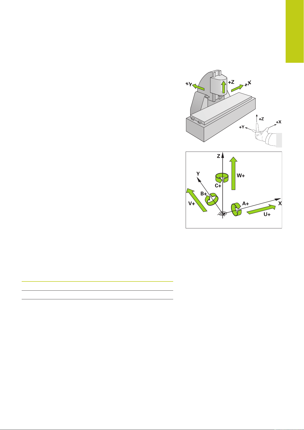
Reference system on milling machines
When using a milling machine, you orient tool movements to the
Cartesian coordinate system. The illustration at right shows how
the Cartesian coordinate system describes the machine axes. The
figure illustrates the right-hand rule for remembering the three
axis directions: the middle finger points in the positive direction of
the tool axis from the workpiece toward the tool (the Z axis), the
thumb points in the positive X direction, and the index finger in the
positive Y direction.
The TNC 640 can control up to 18 axes. The axes U, V and W
are secondary linear axes parallel to the main axes X, Y and Z,
respectively. Rotary axes are designated as A, B and C. The
illustration at lower right shows the assignment of secondary axes
and rotary axes to the main axes.
3
Fundamentals 3.1
Designation of the axes on milling machines
The X, Y and Z axes on your milling machine are also referred to as
tool axis, principal axis (1st axis) and secondary axis (2nd axis). The
assignment of the tool axis is decisive for the assignment of the
principal and secondary axes.
Tool axis Principal axis Secondary axis
X Y Z
Y Z X
Z X Y
TNC 640 | User's ManualDIN/ISO Programming | 1/2015
95
Page 96

3
Programming: Fundamentals, File Management
3.1 Fundamentals
Polar coordinates
If the production drawing is dimensioned in Cartesian coordinates,
you also write the NC program using Cartesian coordinates. For
parts containing circular arcs or angles it is often simpler to give the
dimensions in polar coordinates.
While the Cartesian coordinates X, Y and Z are three-dimensional
and can describe points in space, polar coordinates are twodimensional and describe points in a plane. Polar coordinates have
their datum at a circle center (CC), or pole. A position in a plane can
be clearly defined by the:
Polar Radius, the distance from the circle center CC to the
position, and the
Polar Angle, the value of the angle between the angle reference
axis and the line that connects the circle center CC with the
position.
Setting the pole and the angle reference axis
The pole is set by entering two Cartesian coordinates in one of the
three planes. These coordinates also set the reference axis for the
polar angle H.
Coordinates of the pole
(plane)
X/Y +X
Y/Z +Y
Z/X +Z
Reference axis of the angle
96
TNC 640 | User's ManualDIN/ISO Programming | 1/2015
Page 97

Absolute and incremental workpiece positions
Absolute workpiece positions
Absolute coordinates are position coordinates that are referenced
to the datum of the coordinate system (origin). Each position on the
workpiece is uniquely defined by its absolute coordinates.
Example 1: Holes dimensioned in absolute coordinates
Hole 1 Hole 2 Hole 3
X = 10 mm X = 30 mm X = 50 mm
Y = 10 mm Y = 20 mm Y = 30 mm
Incremental workpiece positions
Incremental coordinates are referenced to the last programmed
nominal position of the tool, which serves as the relative
(imaginary) datum. When you write an NC program in incremental
coordinates, you thus program the tool to move by the distance
between the previous and the subsequent nominal positions. This
is why they are also referred to as chain dimensions.
To program a position in incremental coordinates, enter the
function G91 before the axis.
Example 2: Holes dimensioned in incremental coordinates
3
Fundamentals 3.1
Absolute coordinates of hole 4
X = 10 mm
Y = 10 mm
Hole 5, with respect to 4 Hole 6, with respect to 5
G91 X = 20 mm G91 X = 20 mm
G91 Y = 10 mm G91 Y = 10 mm
Absolute and incremental polar coordinates
Absolute polar coordinates always refer to the pole and the angle
reference axis.
Incremental polar coordinates always refer to the last programmed
nominal position of the tool.
TNC 640 | User's ManualDIN/ISO Programming | 1/2015
97
Page 98

3
Programming: Fundamentals, File Management
3.1 Fundamentals
Selecting the datum
A production drawing identifies a certain form element of the
workpiece, usually a corner, as the absolute datum. When setting
the datum, you first align the workpiece along the machine axes,
and then move the tool in each axis to a defined position relative
to the workpiece. Set the display of the TNC either to zero or to
a known position value for each position. This establishes the
reference system for the workpiece, which will be used for the
TNC display and your part program.
If the production drawing is dimensioned in relative coordinates,
simply use the coordinate transformation cycles (see User’s
Manual for Cycles, Cycles for Coordinate Transformation).
If the production drawing is not dimensioned for NC, set the
datum at a position or corner on the workpiece from which the
dimensions of the remaining workpiece positions can be most
easily measured.
The fastest, easiest and most accurate way of setting the datum is
by using a 3-D touch probe from HEIDENHAIN. See “Setting the
Datum with a 3-D Touch Probe” in the Cycle Programming User’s
Manual.
Example
The workpiece drawing shows holes (1 to 4) whose dimensions are
shown with respect to an absolute datum with the coordinates X=0
Y=0. Holes 5 to 7 are dimensioned with respect to a relative datum
with the absolute coordinates X=450, Y=750. With the DATUM
SHIFT cycle you can temporarily set the datum to the position
X=450, Y=750, to be able to program holes 5 to 7 without further
calculations.
98
TNC 640 | User's ManualDIN/ISO Programming | 1/2015
Page 99

Block number
Path function
Words
Block
Opening programs and entering 3.2
3.2 Opening programs and entering
Organization of an NC program in DIN/ISO format
A part program consists of a series of program blocks. The figure at
right illustrates the elements of a block.
The TNC numbers the blocks of a part program automatically
depending on machine parameter blockIncrement (105409). The
machine parameter blockIncrement (105409) defines the block
number increment.
The first block of a program is identified by %, the program name
and the active unit of measure.
The subsequent blocks contain information on:
The workpiece blank
Tool calls
Approaching a safe position
Feed rates and spindle speeds, as well as
Path contours, cycles and other functions
The last block of a program is identified by N99999999 the
program name and the active unit of measure.
3
After each tool call, HEIDENHAIN recommends
always traversing to a safe position from which the
TNC can position the tool for machining without
causing a collision!
TNC 640 | User's ManualDIN/ISO Programming | 1/2015
99
Page 100

3
Programming: Fundamentals, File Management
3.2 Opening programs and entering
Define the blank: G30/G31
Immediately after initiating a new program, you define an
unmachined workpiece blank. If you wish to define the blank at
a later stage, press the SPEC FCT key, the soft key, and then the
BLK FORM soft key. The TNC needs this definition for graphic
simulation.
You only need to define the workpiece blank if you
wish to run a graphic test for the program!
The TNC can depict various types of blank forms.
Soft key Function
Define a rectangular blank
Define a cylindrical blank
Define a rotationally symmetric blank
Rectangular blank
The sides of the cuboid lie parallel to the X, Y and Z axes. This
blank is defined by two of its corner points:
MIN point G30: the smallest X, Y and Z coordinates of the blank
form, entered as absolute values
MAX point G31: the largest X, Y and Z coordinates of the blank
form, entered as absolute or incremental values
Example: Display the BLK FORM in the NC program
%NEW G71 *
N10 G30 G17 X+0 Y+0 Z-40 *
N20 G31 X+100 Y+100 Z+0 *
N99999999 %NEW G71 *
Program begin, name, unit of measure
Spindle axis, MIN point coordinates
MAX point coordinates
Program end, name, unit of measure
100
TNC 640 | User's ManualDIN/ISO Programming | 1/2015
 Loading...