

Page 1
Technical Manual
TNC 620
NC Software
340 56x-02
October 2010
Page 2

2 HEIDENHAIN Technical Manual TNC 620
Page 3

Contents
1 Update Information
1.1 General Information..........................................................................19
1 Update Information No. 1
1.1 Overview............................................................................................21
1.1.1 Released Service Packs ......................................................21
1.1.2 Released NC Software........................................................21
1.2 NC Software 340 560-01...................................................................22
1.3 NC Software 340 551-04 / NC Software 340 560-02 ......................23
1.3.1 Important Notes on Updating Software ..............................23
1.3.2 Description of the New Functions.......................................28
1.4 NC Software 340 554-xx (TNC 320 Programming Station) ...........44
1.4.1 Description of the New Functions.......................................44
1.5 Hardware ...........................................................................................45
1.5.1 MC 6110 Computer Unit with ProfiBus Interface...............45
1 Update Information No. 2
1.1 Overview............................................................................................47
1.1.1 Released service packs.......................................................47
1.2 Hardware ...........................................................................................47
1.2.1 MC 6110 main computer of the TNC 620...........................47
1 Update Information No. 3
1.1 Overview............................................................................................49
1.1.1 Released service packs.......................................................49
1.2 NC software 340 56x-02 Service Pack 8..........................................49
1.2.1 Description of important changes.......................................49
1.3 Hardware ...........................................................................................50
1.3.1 UEC 11x controller unit with inverter and PLC I/O..............50
October 2010 3
Page 4

2Introduction
2.1 Meaning of the Symbols Used in this Manual...............................53
2.2 Proper Operation...............................................................................53
2.3 Trained Personnel .............................................................................53
2.4 General Information..........................................................................54
2.4.1 HSCI interface.....................................................................57
2.5 Overview of Components ................................................................58
2.5.1 MC main computer, CFR memory card and SIK .................58
2.5.2 CC 6106 controller unit .......................................................60
2.5.3 UEC 11x controller unit with integrated inverter and
PLC......................................................................................61
2.5.4 PLC input/output systems with HSCI interface ..................63
2.5.5 PSL 130 low-voltage power supply unit..............................67
2.5.6 MB 620 Machine Operating Panel......................................69
2.5.7 Handwheels ........................................................................70
2.5.8 Key symbols........................................................................73
2.5.9 Touch probes ......................................................................78
2.5.10 Other accessories ...............................................................80
2.5.11 Documentation....................................................................80
2.6 Brief Description................................................................................81
2.7 Software ............................................................................................93
2.7.1 Designation of the software................................................93
2.7.2 PLC software ......................................................................93
2.7.3 Enabling additional axes or software options......................94
2.7.4 Upgrade functions (Feature Content Level) ........................97
2.7.5 NC software exchange on the TNC 620 .............................98
2.7.6 Installing a service pack ....................................................103
2.7.7 Reversing a software update ............................................104
2.7.8 Special features of the software.......................................105
2.7.9 Firmware update on HSCI devices....................................106
2.7.10 Monitoring hardware changes ..........................................108
2.7.11 Data backup ......................................................................108
2.8 Software Releases ..........................................................................109
2.8.1 NC Software 340 560-xx...................................................109
2.8.2 NC software 340 561-xx ...................................................109
4 HEIDENHAIN Technical Manual TNC 620
Page 5

3 Mounting and Electrical Installation
3.1 General Information........................................................................111
3.1.1 Safety precautions.............................................................111
3.1.2 Degrees of protection .......................................................112
3.1.3 Electromagnetic compatibility ...........................................112
3.1.4 ESD protection..................................................................113
3.2 Environmental Conditions .............................................................115
3.2.1 Heat generation and cooling..............................................115
3.2.2 Humidity............................................................................116
3.2.3 Installation elevation..........................................................116
3.2.4 Mechanical vibration..........................................................116
3.2.5 Mounting Attitude with MC 6110 .....................................117
3.2.6 Mounting Attitude of CC 61xx, UV xxx, UM xxx,
UE 2xx B............................................................................118
3.3 Overview of Hardware....................................................................119
3.4 HSCI..................................................................................................120
3.4.1 Introduction.......................................................................120
3.4.2 Topology............................................................................121
3.4.3 HSCI interface...................................................................122
3.5 Connection Overview for TNC 620...............................................124
3.5.1 MC 6110 main computer ..................................................124
3.5.2 CC 6106 modular controller unit........................................125
3.5.3 UEC 11x: Compact Controller Unit with Inverter and
PLC I/Os ............................................................................126
3.5.4 UEC 11x: Digital PLC inputs/outputs.................................133
3.5.5 PLB 62xx and PLB 61xx ....................................................136
3.5.6 Switching inputs and outputs 24 V– (PLC)........................140
3.5.7 PLB 6xxx: Digital PLC Inputs/Outputs...............................141
3.5.8 PLB 6xxx: Analog PLC Inputs/Outputs..............................143
3.5.9 X121: PROFIBUS connection............................................145
3.5.10 Configuring the PLC Inputs/Outputs with IOconfig...........146
3.6 Power Supply for the TNC 620 ......................................................147
3.6.1 PSL 130 low-voltage power supply unit............................153
3.7 Power Supply for PLC Outputs......................................................161
3.8 Power Supply for PLB 6xxx............................................................162
3.9 Power Supply for Control-Is-Ready Signal...................................163
3.10 Drive Controller Enable ..................................................................164
3.11 Buffer Battery ..................................................................................165
3.12 Encoder Connections .....................................................................166
3.12.1 General information...........................................................166
3.12.2 Position Encoder Input .....................................................167
3.12.3 Input of speed encoder ...................................................169
October 2010 5
Page 6

3.13 Adapters for Encoder Signals ........................................................174
3.14 Connecting the Motor Power Stages (Only CC 61xx) .................178
3.15 Touch Probe Systems.....................................................................179
3.16 Data Interfaces ................................................................................182
3.16.1 USB Interface....................................................................185
3.17 MB 620 Machine Operating Panel .................................................186
3.18 Handwheel Input.............................................................................190
3.18.1 HR 410 portable handwheel..............................................190
3.18.2 HR 130 panel-mounted handwheel...................................192
3.18.3 HRA 110 handwheel adapter ............................................193
3.19 Cable Specifications........................................................................195
3.20 Dimensions......................................................................................196
3.20.1 MC 6110 ...........................................................................197
3.20.2 MB 620 .............................................................................198
3.20.3 CC 6106 ............................................................................199
3.20.4 UEC 11x ............................................................................200
3.20.5 PL 6xxx..............................................................................201
3.20.6 PSL 130.............................................................................201
3.20.7 Adapter block for the data interface..................................202
3.20.8 USB hub............................................................................203
3.20.9 Line-drop compensator .....................................................204
3.20.10 Handwheels ......................................................................204
3.20.11 Touch probes ....................................................................208
3.21 HSCI Connection Overview of the TNC 620 with CC 61xx..........215
3.22 HSCI Connection Overview of the TNC 620 with UEC 11xx .......216
3.23 Grounding diagram for TNC 620 with Modular
HEIDENHAIN Inverter System .......................................................217
3.24 Basic Circuit Diagram for TNC 620 ................................................218
3.25 Cable Overview for TNC 620 with CC 6106 ..................................219
3.26 Cable Overview for TNC 620 with UEC 11x..................................220
3.27 Cable Overview for TNC 620—Accessories ..................................221
6 HEIDENHAIN Technical Manual TNC 620
Page 7

4 Machine Parameters
4.1 General Information........................................................................223
4.2 The “Machine Parameter” Mode of Operation............................225
4.2.1 Calling the configuration editor..........................................225
4.2.2 Entering and Changing Machine Parameters....................227
4.2.3 Accessing Machine Parameters via MP Numbers............238
4.2.4 Managing configuration files .............................................241
4.2.5 Sort File Content ...............................................................241
4.2.6 Attribute Information.........................................................242
4.2.7 Access Protection / Options..............................................244
4.2.8 Update rules......................................................................245
4.2.9 Remove Syntax Error ........................................................255
4.2.10 Resets the update version ................................................255
4.2.11 Backup of Parameters.......................................................256
4.3 User Parameters..............................................................................257
4.3.1 Configuration of the user parameters ...............................258
4.3.2 Example:............................................................................260
4.3.3 XML commands for creating the layout files ....................262
4.4 The KeySynonym function.............................................................265
4.5 Allocation of Configuration Data ..................................................267
4.6 Structure of a Parameter File.........................................................269
4.7 Machine-Parameter Subfiles..........................................................272
4.7.1 Syntax of Machine-Parameter Subfile...............................272
4.7.2 Activating the Machine-Parameter Subfile........................272
4.7.3 Displaying/Editing Data Records in the Configuration
Editor.................................................................................275
4.8 Read or Change Machine Parameters via a PLC Module ............277
4.9 Overview of Machine Parameters .................................................283
4.9.1 “System” Group ...............................................................283
4.9.2 “Channels” Group.............................................................292
4.9.3 “Axes” group....................................................................295
4.9.4 “KeySynonym” group.......................................................300
4.10 Parameter Overview Sorted by MP Numbers..............................301
4.10.1 System configuration and miscellaneous..........................302
4.10.2 Channel-specific parameters.............................................322
4.10.3 Axis-specific parameters ...................................................327
4.10.4 Parameters for configuring the parameter sets ................329
4.11 Overview: iTNC 530 MP Numbers <–> TNC 620 MP
Numbers ..........................................................................................336
4.11.1 Measuring systems and machine axes.............................337
4.11.2 Positioning and regulation.................................................339
4.11.3 PWM interface (DSP) ........................................................341
4.11.4 Spindle control (1st spindle) ..............................................344
4.11.5 Integrated PLC ..................................................................345
4.11.6 Serial interface...................................................................346
4.11.7 Touch probe ......................................................................346
4.11.8 Tool touch probe for tool measurement............................347
4.11.9 Tapping..............................................................................347
4.11.10 Display and programming..................................................348
4.11.11 Machining and Program Run.............................................349
4.11.12 Hardware...........................................................................350
October 2010 7
Page 8

5 Modules and PLC Operands
5.1 Overview of Modules......................................................................351
5.2 Overview of the PLC Operands......................................................357
5.2.1 PLC Operands of the “General Data” Group....................357
5.2.2 PLC Operands of the “Operating Mode Group”
Group ................................................................................359
5.2.3 PLC Operands of the “Machining Channels” Group ........360
5.2.4 PLC Operands of the “Axis” Group..................................362
5.2.5 PLC Operands of the “Spindle” Group.............................364
6 Configuring the Axes and Spindle
6.1 Machine Structure ..........................................................................365
6.1.1 Adapting the control to the machine.................................365
6.1.2 Definition of axes ..............................................................366
6.2 Configuration of Machining Channels ..........................................368
6.2.1 Configuring a machining channel ......................................368
6.2.2 Traversing the reference marks ........................................373
6.2.3 Returning to the contour/block scan .................................374
6.3 Configuration of Axes.....................................................................378
6.3.1 Axis designations and coordinates....................................380
6.3.2 Programmable axes ..........................................................383
6.3.3 Physical axes.....................................................................386
6.3.4 Display of axes on the screen...........................................394
6.3.5 Hirth coupling....................................................................398
6.3.6 Kinematics properties of axes...........................................400
6.3.7 Manual axis (counter axis).................................................402
6.3.8 Introducing a new NC axis into the system ......................404
6.4 Encoders ..........................................................................................415
6.4.1 Type of the position encoder ............................................415
6.4.2 Signal period of encoders..................................................418
6.4.3 Distance-coded reference marks ......................................422
6.4.4 Connecting the encoders, PWM output on the
CC 61xx.............................................................................424
6.4.5 Connecting the encoders to the UEC 11x.........................429
6.4.6 Defining the traverse direction..........................................431
6.4.7 Encoder monitoring...........................................................433
6.4.8 Linear and torque motors..................................................437
6.5 Reading and Writing Axis Information .........................................439
6.5.1 Reading axis information...................................................439
6.5.2 Writing axis information – activating and deactivating
axes...................................................................................445
6.6 Traverse Ranges..............................................................................454
6.6.1 Overwrite software limit switches....................................455
6.7 Lubrication Pulse.............................................................................456
6.8 Controlling Axes by PLC (PLC Axes) .............................................458
8 HEIDENHAIN Technical Manual TNC 620
Page 9

6.9 Axis Error Compensation ...............................................................468
6.9.1 Backlash compensation.....................................................470
6.9.2 Linear axis error compensation .........................................474
6.9.3 Nonlinear axis error compensation....................................476
6.9.4 Compensation of thermal expansion.................................483
6.9.5 Compensation of static friction .........................................485
6.9.6 Compensation of sliding friction........................................486
6.10 Machine Kinematics........................................................................488
6.10.1 Configuring the machine kinematics.................................491
6.10.2 Find/activate kinematics through the PLC.........................511
6.11 Tilting Axes......................................................................................513
6.11.1 “Tilting the working plane” function
(software option 1)............................................................513
6.12 Parallel Axes ....................................................................................518
6.13 Synchronized Axes (Option 24) .....................................................520
6.13.1 Gantry axes .......................................................................520
6.13.2 Master-slave torque control ..............................................530
6.14 Reference Marks..............................................................................541
6.14.1 Definition...........................................................................541
6.14.2 Traversing the reference marks ........................................542
6.14.3 Defining the process of traversing the reference
marks.................................................................................545
6.14.4 “Pass Over Reference Point” operating mode.................552
6.15 The Control Loop ............................................................................556
6.15.1 Block diagram of control loop............................................556
6.15.2 Relation between jerk, acceleration, velocity and
distance.............................................................................557
6.15.3 Geometry filter ..................................................................559
6.15.4 Look-ahead........................................................................561
6.15.5 Interpolator........................................................................571
6.15.6 Nominal position value filter..............................................572
6.15.7 Feed-rate smoothing (software option 2)..........................583
6.15.8 Position controller..............................................................585
6.15.9 Activating and deactivating position control loops ............594
6.15.10 Feed-rate enable................................................................597
6.15.11 Speed controller ................................................................599
6.15.12 Filters in the speed controller and position controller
when using the CC 61xx and CC 424................................603
6.15.13 CC 61xx/CC 424: filter order for separate low-pass
filter in the speed controller ..............................................607
6.15.14 CC 61xx/CC424: peculiarities in weakened-field
operation ...........................................................................608
6.15.15 Active damping of low-frequency oscillations...................610
6.15.16 Acceleration feedforward control......................................612
6.15.17 IPC, holding torque, following error in the jerk phase .......615
6.15.18 HSCI: switching drives on and off, enabling the drive
controller ...........................................................................620
6.15.19 Current controller ..............................................................630
6.15.20 Braking the drives for an EMERGENCY STOP and a
power fail...........................................................................635
6.15.21 Power and torque limiting .................................................638
6.15.22 Controller parameters for manual traverse........................645
6.15.23 Switching parameter sets .................................................646
October 2010 9
Page 10

6.15.24 Synchronous motors in field weakening range .................659
6.15.25 Motor with wye/delta switchover .....................................661
6.15.26 Speed-dependent switching of the PWM frequency ........663
6.15.27 TRC – torque ripple compensation....................................666
6.15.28 Torsion compensation.......................................................669
6.16 Monitoring Functions .....................................................................671
6.16.1 Monitoring the drives........................................................671
6.16.2 Position monitoring ...........................................................673
6.16.3 Movement monitoring ......................................................677
6.16.4 Standstill monitoring .........................................................679
6.16.5 Positioning window...........................................................680
6.16.6 Monitoring of the power supply unit ................................684
6.16.7 Temperature monitoring ...................................................687
6.16.8 I
2
t monitoring ....................................................................691
6.16.9 Momentary utilization of drive motors ..............................702
6.16.10 Status of HEIDENHAIN hardware and software...............704
6.16.11 Motor brake.......................................................................708
6.16.12 Emergency stop monitoring..............................................709
6.16.13 Monitoring functions when using the CC 61xx and
CC 424 ..............................................................................714
6.17 Spindles ...........................................................................................716
6.17.1 Configuring spindles..........................................................716
6.17.2 Position encoder of the spindle.........................................717
6.17.3 Spindle speed encoder......................................................718
6.17.4 Filtering the acceleration values........................................720
6.17.5 Controlling the spindle ......................................................721
6.17.6 Oriented spindle stop (spindle point stop) ........................732
6.17.7 Tapping with floating tap holder and coded
spindle-speed output.........................................................736
6.17.8 Switching the modes of operation ....................................738
6.17.9 Stop spindle at trip dog position........................................740
6.17.10 Spindle of the kinematics model.......................................743
6.17.11 Gear shifting......................................................................744
6.17.12 Tapping..............................................................................744
6.17.13 Operating a second spindle...............................................744
6.17.14 C-axis operation.................................................................746
6.17.15 Volts-per-hertz control mode.............................................748
6.18 Configuring the Controller Unit and Drive Motors......................749
6.18.1 Structure of the CC 61xx and UEC 11x controller
units ..................................................................................749
6.18.2 CC61xx: single-speed and double-speed (software
option #49) ........................................................................751
6.18.3 PWM frequencies with the CC 61xx.................................755
6.18.4 PWM frequency with INDRAMAT “POWER DRIVE”
inverters ...........................................................................757
6.18.5 PWM frequency with SIEMENS “SIMODRIVE”
inverters ............................................................................757
6.18.6 Comparison of the CC 61xx and CC 424 controller
units ..................................................................................760
6.18.7 Configuring the servo motor .............................................763
6.18.8 Field orientation – fundamentals.......................................766
6.18.9 Ascertaining the field angle with the CC 61xx or
CC 424 ..............................................................................768
10 HEIDENHAIN Technical Manual TNC 620
Page 11

6.19 Current Controller Adjustment......................................................776
6.20 Integrated Oscilloscope..................................................................778
6.20.1 Fundamentals....................................................................778
6.20.2 Prepare recording..............................................................780
6.20.3 Record signals...................................................................784
6.20.4 Analyze recording..............................................................786
6.20.5 Saving and loading recordings...........................................789
6.20.6 Circular interpolation test with the integrated
oscilloscope.......................................................................790
6.20.7 Configure the colors of the oscilloscope display...............791
7 Machine Integration
7.1 Display and Operation....................................................................795
7.1.1 Position and status display................................................795
7.1.2 Unit of measurement for display and operation................803
7.1.3 Conversational language ...................................................804
7.1.4 Format of NC programs and cycle display.........................809
7.1.5 Settings for the programming mode of operation.............811
7.1.6 Binary file management ....................................................817
7.1.7 Access rights to drives and directories .............................819
7.1.8 Code numbers...................................................................821
7.1.9 Programming station mode...............................................822
7.1.10 Operating modes / control operation in the operating
mode group.......................................................................825
7.1.11 Control operation in the machining channel ......................829
7.1.12 Error messages and log files.............................................846
7.1.13 TNCguide – context-sensitive help system (user
documentation) .................................................................871
7.1.14 Table editor........................................................................882
7.1.15 Machine datum .................................................................885
7.1.16 Cycles................................................................................888
7.1.17 Window manager (XFCE) ..................................................892
7.2 Small PLC window..........................................................................896
7.3 PLC Soft Keys ..................................................................................900
7.4 Switching the Control On/Off........................................................901
7.4.1 Powering up the control....................................................901
7.4.2 Shutting down the control.................................................904
7.5 Keystroke Simulation .....................................................................911
7.5.1 Control keyboard...............................................................911
7.5.2 Machine operating panel...................................................918
7.6 Electronic Handwheel.....................................................................920
7.6.1 Serial handwheel...............................................................920
7.6.2 Handwheel at position encoder input................................925
7.6.3 Traverse per handwheel revolution ...................................930
7.6.4 Assigning a handwheel to an axis.....................................931
7.6.5 HR 410 portable handwheel..............................................935
7.6.6 HR 150 panel-mounted handwheels with HRA 110
handwheel adapter............................................................937
October 2010 11
Page 12

7.7 Override ...........................................................................................939
7.7.1 Override devices ...............................................................939
7.7.2 Compensation for potentiometers ....................................941
7.7.3 Override functions.............................................................942
7.8 PLC Inputs/Outputs........................................................................946
7.8.1 Diagnosis of the external PL .............................................946
7.8.2 24 V– switching input/outputs ..........................................950
7.8.3 Analog inputs ....................................................................954
7.8.4 Analog outputs..................................................................957
7.9 Incremental Jog Positioning..........................................................959
7.10 Operating Times and System Times.............................................961
7.10.1 Measuring operating times ...............................................961
7.10.2 System time......................................................................967
7.11 Tool Changer ...................................................................................969
7.11.1 Tool and pocket number ...................................................969
7.11.2 Automatic Tool Recognition............................................1000
7.11.3 Controlling the Tool Changer...........................................1001
7.12 Touch Probe...................................................................................1007
7.12.1 Using the Touch Probes..................................................1010
7.12.2 Touch Probe Cycles ........................................................1015
7.12.3 Tool measurement..........................................................1022
7.13 Commissioning .............................................................................1035
7.13.1 Power Module Table and Motor Table............................1035
7.13.2 Preparation......................................................................1044
7.13.3 Commissioning of Digital Axes .......................................1047
7.13.4 Commissioning the Spindle ............................................1064
7.14 Diagnosis with the Online Monitor (OLM) .................................1068
7.14.1 Introduction.....................................................................1068
7.14.2 Using the OLM................................................................1069
7.14.3 Screen Layout .................................................................1071
7.14.4 Group of NC Axes ...........................................................1074
7.14.5 Group of Spindle Commands ..........................................1094
7.14.6 Group of NC Channels ....................................................1096
7.14.7 Hardware Group..............................................................1101
7.14.8 Group of Drive Commands .............................................1114
7.14.9 Auxiliary Group................................................................1115
7.14.10 PLC Group.......................................................................1121
7.14.11 Queue-Trace....................................................................1124
7.14.12 Frequent Causes of Error ................................................1126
12 HEIDENHAIN Technical Manual TNC 620
Page 13

8 PLC Programming
8.1 PLC functions.................................................................................1127
8.1.1 The API 3.0 symbolic memory interface.........................1128
8.1.2 HEIDENHAIN PLC basic program ...................................1134
8.1.3 Selecting the plc programming mode of operation .........1135
8.1.4 PLC main menu...............................................................1136
8.1.5 File management.............................................................1138
8.1.6 The API DATA function ...................................................1139
8.1.7 The WATCH LIST function ..............................................1141
8.1.8 The TABLE function ........................................................1143
8.1.9 The TRACE function........................................................1145
8.1.10 The COMPILE function ...................................................1147
8.1.11 The EDIT function............................................................1148
8.1.12 Diagnostic functions........................................................1151
8.1.13 BUS diagnostics..............................................................1171
8.2 Configure PLC input/output systems .........................................1176
8.3 Operands........................................................................................1178
8.3.1 Overview of operands.....................................................1178
8.3.2 Operand addressing (byte, word, double word)..............1181
8.3.3 Timers and counters .......................................................1182
8.3.4 Fast PLC inputs...............................................................1192
8.4 Data Organization.........................................................................1194
8.4.1 Data organization on the CFR memory card....................1194
8.4.2 Compressing graphic files...............................................1196
8.4.3 Configuring the displayed drives and directories in
the file manager ..............................................................1197
8.4.4 PLC system files ...........................................................1199
8.5 M Functions (M Strobe)................................................................1207
8.5.1 Assigning M functions to the machining channels..........1207
8.5.2 Configuration of M functions...........................................1208
8.5.3 Overview of M functions of the TNC ..............................1216
8.6 S Function (S Strobe) ...................................................................1222
8.6.1 Assigning S functions to the machining channels...........1222
8.6.2 Configuration of S function..............................................1223
8.7 T Functions (T Strobe)..................................................................1233
8.7.1 Assigning T functions to the machining channels ...........1233
8.7.2 Configuration of T functions............................................1234
8.8 Alias Functions (Alias Strobe).....................................................1241
8.8.1 Assigning alias functions to the machining
channels ..........................................................................1241
8.8.2 Configuration of alias functions.......................................1242
8.9 Options for the PLC Run-Time System.......................................1244
October 2010 13
Page 14

8.10 Tables.............................................................................................1247
8.10.1 Creating a new table type ...............................................1248
8.10.2 Defining a table prototype...............................................1259
8.10.3 Creating a new table with the file manager ....................1260
8.10.4 Inserting additional columns in an existing table.............1261
8.10.5 Deleting columns from an existing table.........................1262
8.10.6 Removing column names and column descriptions .......1263
8.10.7 Defining the path for OEM tables ...................................1264
8.10.8 Symbolic names for tables..............................................1264
8.10.9 Editing tables via the PLC ..............................................1266
8.10.10 Access to tables via SQL commands..............................1277
8.10.11 PLC modules for the SQL statements ............................1290
8.11 Data Transfer NC => PLC, PLC => NC..........................................1309
8.11.1 Introduction.....................................................................1309
8.11.2 Data transfer NC program => PLC ("FN19: PLC =" or
"FN29: PLC =").................................................................1310
8.11.3 Q parameters ..................................................................1312
8.11.4 Data transfer NC program => NC (FN17:
SYSWRITE) .....................................................................1314
8.11.5 Data transfer NC => NC program (FN18: SYSREAD).......1326
8.11.6 Data transfer machine parameters => PLC ....................1339
8.11.7 Interrogate PLC operands in the NC program (FN20:
WAIT FOR)......................................................................1341
8.12 Program Creation..........................................................................1342
8.12.1 ASCII editor.....................................................................1342
8.12.2 Program format...............................................................1342
8.12.3 Program structure ...........................................................1343
8.13 Command Set................................................................................1344
8.13.1 Overview.........................................................................1344
8.13.2 LOAD (L) .........................................................................1347
8.13.3 LOAD NOT (LN) ..............................................................1349
8.13.4 LOAD TWO’S COMPLEMENT (L–).................................1351
8.13.5 LOAD BYTE (LB) .............................................................1352
8.13.6 LOAD WORD (LW) .........................................................1352
8.13.7 LOAD DOUBLE WORD (LD)...........................................1353
8.13.8 ASSIGN (=)......................................................................1353
8.13.9 ASSIGN BYTE (B=)..........................................................1354
8.13.10 ASSIGN WORD (W=)......................................................1355
8.13.11 ASSIGN DOUBLE WORD (D=) .......................................1355
8.13.12 ASSIGN NOT (=N)...........................................................1356
8.13.13 ASSIGN TWO’S COMPLEMENT (=–) .............................1356
8.13.14 SET (S).............................................................................1357
8.13.15 RESET (R)........................................................................1358
8.13.16 SET NOT (SN)..................................................................1359
8.13.17 RESET NOT (RN).............................................................1360
8.13.18 AND (A) ...........................................................................1361
8.13.19 AND NOT (AN) ................................................................1363
8.13.20 OR (O) .............................................................................1365
8.13.21 OR NOT (ON) ..................................................................1367
8.13.22 EXCLUSIVE OR (XO).......................................................1369
8.13.23 EXCLUSIVE OR NOT (XON)............................................1371
8.13.24 ADDITION (+)..................................................................1373
8.13.25 SUBTRACTION (–)...........................................................1374
8.13.26 MULTIPLICATION (X)......................................................1375
8.13.27 DIVISION (/).....................................................................1376
14 HEIDENHAIN Technical Manual TNC 620
Page 15

8.13.28 REMAINDER (MOD) .......................................................1377
8.13.29 INCREMENT (INC)...........................................................1377
8.13.30 DECREMENT (DEC)........................................................1378
8.13.31 EQUAL TO (==)...............................................................1378
8.13.32 LESS THAN (<)................................................................1379
8.13.33 GREATER THAN (>) ........................................................1380
8.13.34 LESS THAN OR EQUAL TO (<=) ....................................1381
8.13.35 GREATER THAN OR EQUAL TO (>=).............................1382
8.13.36 NOT EQUAL (<>) ............................................................1383
8.13.37 AND [ ] (A[ ]) ....................................................................1384
8.13.38 AND NOT [ ] (AN[ ]) .........................................................1385
8.13.39 OR [ ] (O[ ]) ......................................................................1385
8.13.40 OR NOT [ ] (ON[ ]) ...........................................................1386
8.13.41 EXCLUSIVE OR [ ] (XO[ ])................................................1386
8.13.42 EXCLUSIVE OR NOT [ ] (XON[ ]) .....................................1386
8.13.43 ADDITION [ ] (+[ ])...........................................................1386
8.13.44 SUBTRACT [ ] (–[ ]) ..........................................................1387
8.13.45 MULTIPLY [ ] (x[ ])...........................................................1387
8.13.46 DIVIDE [ ] (/[ ])..................................................................1388
8.13.47 REMAINDER [ ] (MOD[ ]) ................................................1388
8.13.48 EQUAL TO [ ] (==[ ])........................................................1388
8.13.49 LESS THAN [ ] (<[ ]).........................................................1389
8.13.50 GREATER THAN [ ] (>[ ]).................................................1390
8.13.51 LESS THAN OR EQUAL TO [ ] (<=[ ]) .............................1390
8.13.52 GREATER THAN OR EQUAL TO [ ] (>=[ ])......................1390
8.13.53 NOT EQUAL [ ] (<>[ ]).....................................................1390
8.13.54 SHIFT LEFT (<<)..............................................................1391
8.13.55 SHIFT RIGHT (>>)...........................................................1392
8.13.56 BIT SET (BS)....................................................................1393
8.13.57 BIT CLEAR (BC)...............................................................1394
8.13.58 BIT TEST (BT)..................................................................1395
8.13.59 PUSH DATA ONTO THE DATA STACK (PS) ...................1396
8.13.60 PULL DATA FROM THE DATA STACK (PL)....................1397
8.13.61 PUSH LOGIC ACCUMULATOR ONTO THE DATA
STACK (PSL)....................................................................1397
8.13.62 PUSH WORD ACCUMULATOR ONTO THE DATA
STACK (PSW)..................................................................1398
8.13.63 PULL LOGIC ACCUMULATOR FROM THE DATA
STACK (PLL)....................................................................1398
8.13.64 PULL WORD ACCUMULATOR FROM THE DATA
STACK (PLW) ..................................................................1399
8.13.65 UNCONDITIONAL JUMP (JP).........................................1399
8.13.66 JUMP IF LOGIC ACCUMULATOR = 1 (JPT)...................1400
8.13.67 JUMP IF LOGIC ACCUMULATOR = 0 (JPF)...................1401
8.13.68 CALL MODULE (CM)......................................................1401
8.13.69 CALL MODULE IF LOGIC ACCUMULATOR = 1
(CMT)...............................................................................1401
8.13.70 CALL MODULE IF LOGIC ACCUMULATOR = 0
(CMF)...............................................................................1402
8.13.71 END OF MODULE, END OF PROGRAM (EM)................1403
8.13.72 END OF MODULE IF LOGIC ACCUMULATOR = 1
(EMT)...............................................................................1403
8.13.73 END OF MODULE IF LOGIC ACCUMULATOR = 0
(EMF)...............................................................................1403
8.13.74 LABEL (LBL)....................................................................1403
October 2010 15
Page 16

8.14 INDEX Register (X Register).........................................................1404
8.15 Commands for String Processing................................................1406
8.16 LOAD STRING (L) ..........................................................................1408
8.17 ADD STRING (+) ............................................................................1408
8.18 STORE STRING (=)........................................................................1408
8.19 OVERWRITE STRING (OVWR) .....................................................1409
8.20 EQUAL TO Command for String Processing (==) ......................1410
8.21 LESS THAN Command for String Processing (<).......................1410
8.22 GREATER THAN Command for String Processing (>)...............1410
8.23 LESS THAN OR EQUAL TO Command for String
Processing (<=)..............................................................................1411
8.24 GREATER THAN OR EQUAL TO Command for String
Processing (>=)..............................................................................1411
8.25 NOT EQUAL Command for String Processing (<>)....................1412
8.26 Modules for String Processing ....................................................1413
8.27 Submit programs..........................................................................1416
8.28 Calling the Submit Program (SUBM)..........................................1417
8.29 Interrogating the Status of a Submit Program (RPLY)..............1417
8.30 Canceling a Submit Program (CAN)............................................1418
8.31 Cooperative Multitasking.............................................................1420
8.31.1 Starting a Parallel Process (SPAWN)...............................1420
8.31.2 Control of events.............................................................1421
8.32 Constants Field (KF)......................................................................1427
8.33 Program Structures ......................................................................1428
8.33.1 IF ... ELSE ... ENDI structure...........................................1429
8.33.2 REPEAT ... UNTIL Structure............................................1429
8.33.3 WHILE ... ENDW structure .............................................1430
8.34 CASE branch..................................................................................1430
8.35 Linking Files...................................................................................1432
8.36 USES STATEMENT (USES)..........................................................1432
8.37 GLOBAL Statement (GLOBAL) ....................................................1434
8.38 EXTERN STATEMENT (EXTERN).................................................1434
8.39 PLC Modules..................................................................................1435
8.39.1 Markers, Bytes, Words, and Double Words ...................1435
8.39.2 Number conversion.........................................................1438
16 HEIDENHAIN Technical Manual TNC 620
Page 17

9 Data Interfaces
9.1 Introduction...................................................................................1443
9.2 The Ethernet Interface..................................................................1444
9.3 Connecting the Control to the Network.....................................1445
9.3.1 Configuring the control’s network address .....................1445
9.3.2 Configuring network access to other devices
(mount)............................................................................1447
9.3.3 Overview of functions for configuring the network ........1449
9.4 HSCI Interface................................................................................1451
9.5 The USB Interface of the Control (USB 1.1) ...............................1453
9.6 The Serial Interface of the Control ..............................................1456
9.6.1 RS-232-C/V.24 interface..................................................1456
9.7 Configuring the Serial Interface...................................................1459
9.7.1 Control characters...........................................................1459
9.7.2 Configuration of interfaces..............................................1460
9.8 Data Transmission Protocols.......................................................1472
9.8.1 Standard communications protocol.................................1472
9.8.2 Communications protocol with block check
character..........................................................................1474
9.8.3 LSV2 transmission protocol.............................................1477
9.9 Saving and Loading Files .............................................................1478
9.10 Configuring the Control for TeleService 2.0...............................1479
9.11 Data Transfer by PLC ....................................................................1482
9.11.1 PLC modules...................................................................1482
10 Index
October 2010 17
Page 18

18 HEIDENHAIN Technical Manual TNC 620
Page 19

1 Update Information
1.1 General Information
Update Information for the TNC 620 appears at irregular intervals, often as part
of a new software version. This is preliminary information in PDF format,
containing brief descriptions of new software functions as well as new
hardware components. After the Update Information has been published, the
new items are included in the TNC 620 Technical Manual.
Each Update Information is saved in the HEIDENHAIN FileBase on the
Internet, where registered users can access it under http://
filebase.heidenhain.de.
Registered users of the HEIDENHAIN FileBase on the Internet receive an
e-mail notification when a new Update Information appears.
November 2009 1.1 General Information 19
Page 20

20 HEIDENHAIN Technical Manual TNC 620
Page 21

1 Update Information No. 1
1.1 Overview
1.1.1 Released Service Packs
The following service packs have been released for NC software 340 56x-01:
Service pack 1: 340 56x-01 SP1 First release: September 2008
Service pack 2: 340 56x-01 SP2 October 2008
Service pack 3: 340 56x-01 SP3 December 2008
1.1.2 Released NC Software
The following NC software has been released:
NC software 340 560-02
NC software 340 561-02
NC software 340 564-02
November 2009 1.1 Overview 21
Page 22
1.2 NC Software 340 560-01
Warning
Service packs
When needed, HEIDENHAIN prepares service packs for the various
versions of the NC software. Registered customers can download these
service packs from the HEIDENHAIN FileBase on the Internet. Installation
of a service pack in addition to the already installed NC software
implements important error fixes. Please ensure that the NC software
always contains the latest service pack before you ship the machine.
Perform all tests required of the machine or the NC software again after
having installed the service pack.
The following service packs have been released for NC software 340 560-01:
Service pack 1 NC software Release
340 560-01 SP1 340 560-01 First release in
Service pack 2 NC software Release
340 560-01 SP2 340 560-01 October 2008
Service pack 3 NC software Release
340 560-01 SP3 340 560-01 December 2008
September 2008
22 HEIDENHAIN Technical Manual TNC 620
Page 23

1.3 NC Software 340 551-04 / NC Software 340 560-02
Note
Note
Note
Note
1.3.1 Important Notes on Updating Software
Please remember the following important information when updating the
software versions listed below:
TNC 320: 340 551-03 to 340 551-04 or
TNC 620: 340 560-01 to 340 560-02
If you are using linear encoders with EnDat interface or motor encoders
with EnDat interface for position measurement on your machine, you must
carry out the following step.
Move the EnDat axes to known positions before the update:
A function for monitoring the SRAM contents for consistency will be
introduced with new NC software. After the software update, all EnDat axes
will therefore display the error message S-RAM contents of axis are
invalid. At the same time, the control will display a dialog box for
confirmation, in which the current (the displayed) position of the axis is
compared with the physical (switch-off) position.
Move the axes to known positions before the update.
Write down the switch-off positions.
After the control has booted with the new software for the first time,
confirm the positions of the EnDat axes.
HEIDENHAIN recommends:
Making a backup of the control (e.g. with TNCbackup), before updating the
NC software.
Saving your current machine configuration. The configuration editor (DATA
BACKUP soft key) can be used for this purpose.
If you later want to undo the software update and return to the previous
software version, you need the saved configuration data of the old version!
Please perform the update of the NC software as described in the Technical
Manual in Chapter 2 "NC Software Exchange".
Be sure to remember the important information about the software update,
which is provided on the following pages.
November 2009 1.3 NC Software 340 551-04 / NC Software 340 560-02 23
Page 24

Checking and saving new machine parameters:
Warning
After having installed the new NC software and rebooted the control, you
must check and confirm the new machine parameters. The MOD dialog box
appears on the screen:
Enter the MP code number 95148 and confirm your entry with the ENT key.
Press the MORE FUNCTIONS soft key.
Press the UPDATE RULES soft key.
Check the listed update rules. Each entry in the list stands for a new
parameter that was added to the system by the update.
Exit the UPDATE RULES with the END soft key.
Press the CONFIG DATA soft key.
Before the configuration editor opens, an informational window is displayed,
reporting the removal of the CfgRestorePosition machine parameter. Press
the NEXT soft key.
All new machine parameters are marked with a red exclamation point in the
configuration editor. The control indicates if certain machine parameters are
faulty. Please ignore these messages for the time being.
Important step: Press the SAVE soft key.
The Configuration data changed dialog box opens. Press the SAVE soft key
again. The new machine parameters are now automatically saved in the
*.cfg files.
Press the END soft key and exit the Machine Parameter Programming
operating mode by pressing the END soft key again.
The control then continues booting.
When the control has booted up for the first time after the software update,
the internal firmware of HSCI components must be updated.The control
displays the error message Firmware update required.
After you have acknowledged the displayed error message, the control will
start the update process automatically.
Never shut down the control while the firmware is being updated –
otherwise the control will need servicing!
After the update is finished, the control displays another message on the
screen. After you have acknowledged the message, the control will shut
down automatically. Switch off the machines and restart the control.
24 HEIDENHAIN Technical Manual TNC 620
Page 25

Note
Due to a software update regarding the evaluation of parameter
Note
MP_signCorrNominalVal (400002), you must check whether the spindle
turns in the correct direction:
Check the direction of spindle rotation, and correct it if required:
After the booting process, the control displays the error message Check the
parameter for the direction of spindle rotation!.
Acknowledge the error message.
It is essential that you check now whether the spindle turns in the correct
direction. Program a function, such as M3 or M19, and observe the direction
of spindle rotation.
If required, use parameter MP_signCorrNominalVal (400002) or
MP_signCorrActualVal (400001) to define the direction of spindle rotation
correctly, see „Defining the Traverse Direction“ on page 419.
In the first TOOL CALL after the software update, the control may display
the warning Pocket table might be inconsistent. In this case, please note
the following information:
Check the pocket table and correct it if required:
Up to now, the control allowed you to enter „0“ for zero tool T0 in the
spindle pocket. This entry is no longer permissible with the new NC
software. The control issues the warning mentioned above. The column
location for the zero tool in the spindle pocket must now be empty. Proceed
as follows to correct the pocket table:
Open the pocket table and press the EDITING ON soft key.
Delete the entry "0" for zero tool T0.
November 2009 1.3 NC Software 340 551-04 / NC Software 340 560-02 25
Page 26
Note
The definition file of the symbolic programming interface API 3.0 has been
Note
expanded. You must perform the step described below in order for the PLC
program to be compiled successfully after the update.
Replace the apimarker.def file:
During the update of the NC software, a new version of the apimarker.def
file was automatically copied to the PLC partition of the control. Proceed as
follows:
Switch to the Programming mode of operation.
Enter the MOD code number 807667 to switch to the PLC Programming
mode of operation.
Open the File Manager with the PGM MGT key.
Switch to the PLC:\proto\plc directory.
Copy the apimarker.def file to the program directory of your PLC program.
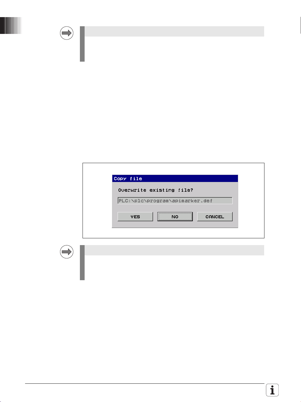
Overwrite the existing apimarker.def file:
Please also copy the apimarker.def file to your PC as well, and add it to the
PLCdesignNT project. Otherwise, during the next transfer of PLC project
files to the control, the file might be overwritten by the old version.
26 HEIDENHAIN Technical Manual TNC 620
Page 27

Note
Please observe the following note if you
are using the HEIDENHAIN PLC Basic Program.
It is essential that you check and modify the PLC program:
The behavior of the symbolic API marker NN_ChnProgCancel (NC program
cancellation) has been changed: NN_ChnProgCancel will now be set every
time the NC program is canceled. For a normal end of program,
NN_ChnProgEnd will be set. The NN_ChnProgCancel marker remains set
during the complete Cancel cycle and beyond the program end until the next
NC program is started.
When a program is canceled, the NN_ChnProgEnd marker will not be set.
The end of program run, including the execution of a Cancel cycle, has been
reached when NN_ChnControlInOperation is reset. NN_ChnProgCancel
and NN_ChnProgEnd will be reset when NN_ChnControlInOperation is
set again.
If both NN_ChnProgCancel and NN_ChnControlInOperation are set, this
indicates that the Cancel cycle is being executed.
Module 9429 or 9320 can be used to inquire the reason for the program
cancellation.
Please check the PLC basic program and make the following changes if
necessary:
German: Biblioth.src
;External/Internal STOP
L ApiChn.NN_ChnProgCancel
AN ML_Internal_STOP
= MG_Impuls_Internal_STOP
L ApiChn.NN_ChnProgCancel
= ML_Internal_STOP
English: Library.src
;External/Internal STOP
L ApiChn.NN_ChnProgCancel
AN ML_Internal_STOP
= MG_pulse_internal_stop
L ApiChn.NN_ChnProgCancel
= ML_Internal_STOP
November 2009 1.3 NC Software 340 551-04 / NC Software 340 560-02 27
Page 28
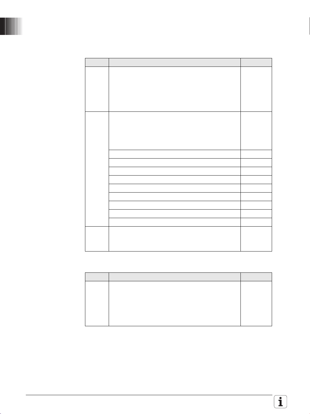
1.3.2 Description of the New Functions
New software
options
You can enable the following new software options by entering a code
number. HEIDENHAIN can give you the code number after having been
informed of the SIK number:
Option Description ID
#24 Gantry Axes
In gantry axes, two servo-controlled axes are coupled
so that they can only move simultaneously. The
gantry axes behave like a single drive. The main axis
is referred to as the master, and the tracking axis as
the slave.
#41 Additional Language
Enabling of additional conversational languages. The
languages listed below can be ordered. Please
contact HEIDENHAIN if you required additional
conversational languages.
Slovenian 530 184-01
Slovak 530 184-02
Latvian 530 184-03
Norwegian 530 184-04
Korean 530 184-06
Estonian 530 184-07
Turkish 530 184-08
Romanian 530 184-09
Lithuanian 530 184-10
#46 Python OEM Process
Possibility of running Python processes on the
control.
670 455-01
579 650-01
Enhanced software option:
Option Description ID
#9 Software Option 2 (only TNC 620):
If there are especially high requirements on the
surface quality, a filter for smoothing the feed rate
(MP_filterFeedTime) and two new axis-specific jerk
parameters (MP_axPathJerk and MP_axPathJerkHi)
are available.
28 HEIDENHAIN Technical Manual TNC 620
617 921-01
Page 29

Overview of the
Note
improvements
A summary of the improvements in NC software 340 551-04 and 340 560-02
is given below. For more detailed information, please refer to the Technical
Manual sections indicated in the brief descriptions given below.
Machine
Configuration
New: Search for the iTNC MP number in the configuration editor
For numerous machine parameters, the compatible iTNC MP number is
stored in the help text in the configuration editor. Up to now, it has not been
possible to search the configuration for these numbers. The search function
of the configuration editor now enables you to search for the iTNC MP
number (selection: MP number). See “Finding / Replacing” on page 236.
New: Separate parameter numbers for OEM parameters
In order for the OEM to group the parameters in the configuration editor
according to his own needs, or to make them easier to find, there is now a
separate number range for the OEM. Numbers 900000 to 999999 are
reserved for the OEM. For those parameters for which an OEM number is
defined, this number is shown instead of the HEIDENHAIN number. The
numbers are to be defined in the
%OEM%\config\layout\PlcUniqueNumbers.xml file. If the file is missing or
empty, no OEM numbers will be displayed. For more information, see „User
Parameters“ on page 257
Expanded: OEM motor table (only digital control, TNC 620)
Until now, if the OEM-specific motor table (path:
PLC:\table\motor_oem.mot) was missing, a warning was issued and the
user had to create the table himself. Now no warning will be issued. The
control itself creates a new blank table as soon as the MP_motName
(401301) parameter is edited. If the OEM motor table exists but columns are
missing, then the columns that exist in the SYS motor table will be added
when copying. The control indicates which columns were not copied.
Expanded: Saving update rules
If the user tries to exit the configuration editor without saving the changes
made by the update rules, a dialog window appears prompting the user to
save the data. The configuration editor cannot be exited until the data are
saved, see "Update rules" on page 245.
The first restart of the control after the update cannot be continued without
saving the configuration changes made by the update rules.
November 2009 1.3 NC Software 340 551-04 / NC Software 340 560-02 29
Page 30

Machine
parameters
new/expanded/
changed
MP number Config object Parameter Description of change
100201 CfgMachineSimul MP_simMode When the new value Delivery is
102902 CfgFileType MP_standardEditor "TEXT-EDITOR“ can now be selected
103502 CfgPlcTimer MP_value The input range of the parameter was
104300
104400
105201 CfgSystemTime MP_offsetToUTC Values with decimal places can now
114103 CfgTool
201203 CfgRotWorkPlane MP_planeCalcMode Parameter removed – obsolete
CfgPlcOverrideDev
CfgPlcOverrideS
Measurement
Expanded/changed machine parameters
set, during startup of the control all
axes are set to the test mode, and a
switch-on of the axes is prevented.
The user should then be able to
start the control, even with an
incomplete or faulty axis
configuration in order to put the
axes into operation. After the
configuration of all axes has been
completed, the control can be
switched to full operation
(FullOperation).
If Delivery, CcAndExt or CcOnly is
set, the control now no longer
outputs any analog nominal values.
in order to assign the ASCII editor of
the control to a file type.
expanded from 1 000 to 1 000 000
seconds (corresponds to approx. 11.5
days).
– The reaction of the parameters under
CfgPlcOverrideDev, CfgPlcOverrideS,
CfgPlcOverrideF and
CfgPlcOverrideR was changed from
NOTHING to RESET. The control
must now be rebooted after a
parameter change.
be entered for time differences to
universal time (GMT). This is
necessary for parts of Australia (+8.5
and +9.5 hours) and Kazakhstan (+3.5
hours), for example. Also, the
maximum value was extended from
+13 to +14 [hours].
MP_probingDirRadial The parameter defines the probing
direction for tool radius
measurement. Z_Positive and
Z_Negative can now also be selected,
because the control now also
supports mounting the TT tool touch
probe in these axis directions, see
page 1024.
30 HEIDENHAIN Technical Manual TNC 620
Page 31

MP number Config object Parameter Description of change
201205 CfgRotWorkPlane MP_autoMoveAxes Parameter MP_autoPosOfRotAxes
was renamed to MP_autoMoveAxes.
Extended description, see page 514
400011 CfgAxisHardware MP_posEncoder
Resistor
New machine parameters:
MP number Config object Parameter Description
101608 CfgShutDown MP_powerOffDevice Optional parameter – Number of a
101609 MP_powerOffSlot Optional parameter - Slot number of
102907 CfgFileType MP_protect Disables filtering or editing of a file
104018 CfgPlcSStrobe MP_cuttingSpeed Optional parameter – If parts of the
105409 CfgEditorSettings MP_blockIncrement Setting the block number increment
105410 MP_useProgAxes Specifies which axis configuration is
105411 MP_enableStraightCut This optional parameter is used to
114205 CfgTTRoundStylus MP_stylusAxis This optional parameter is used to
The default value of the parameter
was changed from without to
120 ohm.
device in the HSCI string (PL, MB) on
which the control is to set an output
during shutdown, see page 908.
the HSCI device specified in
MP_powerOffDevice on which the
control is to set the output after
shutdown, see page 908.
type, see page 1252.
configuration indicate the symbolic
name or number of a word marker to
which the cutting speed is copied.
of ISO programs between 0 and 250.
Extended description, see page 815.
used in the Programming mode of
operation. Extended description, see
page 816
enable (TRUE) or disable (FALSE)
paraxial positioning blocks. As a
default, paraxial positioning blocks are
allowed. Extended description, see
page 816
specify the orientation of the TT tool
touch probe in the working space, see
page 1027.
November 2009 1.3 NC Software 340 551-04 / NC Software 340 560-02 31
Page 32

MP number Config object Parameter Description
106501 CfgConfigSettings MP_undoListSize Defines the number of entries in the
parameter change list, see page 235.
106502 MP_suppressUsrMsg This parameter is used to suppress
the warning Key is non-functional,
see page 870.
106503 MP_dispParam
Numbers
106504 MP_hideWrite
Protected
116601 CfgDiagnosis MP_osTraceFileSize Maximum log file size for diagnostic
116602 MP_tcpTraceFileSize Maximum log file size for diagnostic
116603 MP_krnlTraceFileSize Maximum log file size for diagnostic
116604 MP_traceDir Target directory for log files, see page
116605 MP_ncTraceFileSize File size for diagnostic messages
201206 CfgRotWorkPlane MP_rotPreference Cycle 19 and Plane function: Define
201513 CfgLaPath MP_filterFeedTime Time constant of the filter for
201719 CfgPlcToolChange MP_sequText Script for tool-change sequence.
201720 MP_sequTint Script for tool-change sequence.
202904 CfgKinCompos
Model
300205 CfgAxisPropKin MP_parAxComp Definition of compensation for parallel
401414 CfgController
Comp
MP_tiltingAllowed This optional parameter is used to
MP_compSwitchOff TRC (Torque Ripple Compensation)
Specifies whether MP numbers or
symbolic names are displayed in the
parameter change list, see page 235.
If the parameter is set to TRUE,
write-protected parameters are
hidden in the configuration editor, see
page 244.
messages of the operating system,
see page 869.
messages of the network, see page
869.
messages of NC kernel, see page
870.
868
from the NC software, see page 869
the realization of the tilt position.
Extended description, see page 515
smoothing the feed rate (software
option 2), see page 584.
Defines the tool-change sequence for
calling an external tool without
loading it in the spindle
Defines the tool-change sequence for
calling an internal tool without loading
it in the spindle
define whether tilting the working
plane is allowed for the kinematics
model, see page 498.
minor axes, see page 518.
can be switched off by setting bit 0,
see page 668.
32 HEIDENHAIN Technical Manual TNC 620
Page 33

MP number Config object Parameter Description
401703 CfgLaAxis MP_axPathJerk (only software option 2)
Axis-specific maximum jerk on the
path. This value limits the jerk in
traverse direction, see page 568
401704 MP_axPathJerkHi (only software option 2)
Axis-specific maximum jerk on the
path for feed rates greater than
MP_maxG1Feed, see page 568.
402301 CfgAxisCoupling MP_masterAxis Synchronized axes: Assign a master
axis to the slave axis, see page 525.
402302 MP_mode Synchronized axes: Mode of the
coupling, see page 525.
402303 MP_type Synchronized axes: Type of coupling,
see page 525.
402304 MP_typeOfOffset Synchronized axes: The parameter
specifies how the position offset
between master and slave axis is
treated, see page 525.
402305 MP_posOffset Synchronized axes: Value of the
position offset with closed coupling,
see page 526.
402306 MP_offsetFeed Synchronized axes: The velocity with
which an offset between the master
axis and the slave axis is
compensated for, see page 526.
402307 MP_maxPosDiff Synchronized axes: Synchronization
monitoring – deletable emergency
stop message, see page 526.
402308 MP_ultimatePosDiff Synchronized axes: Synchronization
monitoring – non-deletable
emergency stop message, see page
526.
402309 MP_scalingFactor Synchronization axes: Scaling factor
for calculating the slave position, see
page 526.
402310 MP_torqueBias Synchronization axes: Tensioning
torque between master and slave for
master-slave torque control (entry for
the slave axis), see page 538.
402311 MP_propGain Synchronization axes: P factor of the
torque controller for master-slave
torque control (entry for the slave
axis), see page 538.
402312 MP_torqueDistrFactor Synchronization axes: Factor for
variable torque distribution for
master-slave torque control (entry for
the slave axis), see page 538.
November 2009 1.3 NC Software 340 551-04 / NC Software 340 560-02 33
Page 34

MP number Config object Parameter Description
402313 MP_speedCorrect
Ratio
402314 MP_inverseVelocity Synchronization axes: Reversal of the
402315 MP_accFilterTime Synchronization axes: Time constant
Synchronization axes: Speed
compensation ratio for master-slave
torque control (entry for the slave
axis), see page 538.
algebraic sign of the nominal speed
value, see page 539.
for filtering the acceleration curve,
see page 527.
34 HEIDENHAIN Technical Manual TNC 620
Page 35

Operation and
technology
New: TNCguide – The context-sensitive help system of the TNC
The browser-based, context-sensitive help system TNCguide is now
available on the control. TNCguide is based on the Mozilla browser and
displays CHM help files. You can download the control's respective User's
Manual in CHM format from the HEIDENHAIN home page and transfer it to
the control. For more information and web links to TNCguide, refer to
„TNCguide – context-sensitive help system (user documentation)“ on
page 871.
New: Window manager (XFCE)
The new NC software provides a window manager (XFCE) on the control.
The window manager helps you organize the user interface and it makes the
control easier to operate. This will result in minor changes in the graphical
interface of the TNC. The operation of the control remains the same,
however. For more information, see „Window manager (XFCE)“ on
page 892
New: Software option #46 (Python OEM Process)
With the “Python OEM Process” option, the OEM can use a powerful,
object-oriented programming language within the control (PLC). Python is an
easy-to-learn script language that supports the use of all necessary
high-level language elements. Python is widely known among programming
experts.
"Python OEM Process" can be used for machine functions and complex
calculations, as well as to display special information. It provides
comprehensive possibilities for realizing user-specific and machine-specific
software solutions, e.g. special algorithms for tool calculation or custom
user interfaces for special functions. Freely definable windows up to the
size of the control screen can be displayed for visualization.
A separate documentation, additional PC tools for debugging and for the
development of user interfaces as well as example programs are available
for Python OEM Process. You can download the files from the
HEIDENHAIN FileBase free of charge: "PC Software > Python“ category.
New: Expanded status display
A new, expanded status display is available in the machine operating
modes. It is activated by the POSITION + STATUS soft key. For more
information, see the User's Manual.
November 2009 1.3 NC Software 340 551-04 / NC Software 340 560-02 35
Page 36

Expanded: File manager
The following improvements were made in the file manager (PGM MGT
key):
• When copying especially large files, the progress is displayed. Up to
now, the CANCEL button was unavailable (dimmed) and had no
function. Now the copying process is canceled when the CANCEL
button or soft key is pressed.
• The file manager now stores the current file sorting criteria, active file
filters and the active graphics preview in non-volatile memory, so that
these settings are still active after the control is restarted.
• Write-protected files are indicated by a red padlock in the file manager.
Now, NC programs currently being run in one of the Program Run
modes of operation are indicated by a blue padlock. This makes it
possible to distinguish whether the file is actually write-protected, or
simply cannot be changed because it is currently being executed.
Symbol Description
The file is currently being executed in one of the
Program Run modes of operation and cannot be
changed.
The file is write-protected.
Enhanced: Update of NC software
The NC software can now also be updated while it is running. The new MOD
key 231019 was therefore introduced, see "Start update while software is
running" on page 102.
Enhanced: Log
The display of the control's log was improved. The accumulated keystrokes
are now stored simultaneously with the control events in the log and are
displayed in table view.
In order to be able to track machine operation or machine conditions
systematically, detailed additional information is entered and stored
simultaneously with all important log entries, such as keystrokes, errors,
system errors or warnings, see "Error messages and log files" on page 846.
Enhanced: Display of DSP software version
After pressing the MOD key, the version number of the DSP software and
the link date are already displayed before the PLC program is compiled in the
Programming mode.
Enhanced: Display of configuration errors during start-up
If configuration errors occur during control start-up, the Error during
start-up message appears instead of Power interrupted. Also, the error
messages for the incorrect configuration data, which are triggered by the
applications, are displayed individually.
36 HEIDENHAIN Technical Manual TNC 620
Page 37

Machine
interfacing
New: Additional data types for table columns
The control supports additional data types for columns in NC tables. The
FEED_CUT column data type applies to the cutting speed in units of m/min
or feet/min. The FEED_ROT column data type applies to the feed rate per
revolution in units of mm/rev or inch/rev. As usual, the new column data
types are listed as enumeration values of parameter MP_unit (105602) of
the configuration object CfgColumnDescription.
Enhanced: Integrated oscilloscope – Selection of symbolic operands
In the MIOTC dialog (dialog box for selecting markers, inputs, outputs,
timers and counters) in the integrated oscilloscope, symbolic API operands
can now also be selected and displayed conveniently in a list. See “Setup
for digital signals” on page 783.
New: Integrated oscilloscope – Circular interpolation test
A circular interpolation test can now be performed with the integrated
oscilloscope. See “Circular interpolation test with the integrated
oscilloscope” on page 790.
New: Test of internal EMERGENCY STOP by key code
For test purposes, an internal EMERGENCY STOP can be simulated in order
to inspect the correct wiring of the machine. The control-is-ready output is
reset. The NC and PLC are no longer operable. It is essential that you
support hanging axes before the test in order to prevent damage to the
machine in case of error. Enter the key code 6871232 under MOD to start
the test. Enter the key code again to reset the control status to "ready for
operation."
Configuring the
axes and spindle
New: Support of synchronized axes
In gantry axes, tandem tables, etc., two servo-controlled axes are coupled
so that they can move only simultaneously. The main axis is referred to as
the master, and the tracking axis as the slave. In master-slave torque
control, two motors (master and slave) are mechanically coupled. Because
of the coupling, only one position encoder is required. The motor to which
the position encoder is assigned is the master.
Software option #24 is required for synchronized axes. For more
information, see “Gantry axes” on page 520 and “Master-slave torque
control” on page 530.
New: Compensation of minor axes U, V, W
The control can now display the compensated position value of the
movements of the parallel minor axes U, V, W, and compensate them with
the principal axis. The new conversational commands PARAXCOMP and
PARAXMODE are available for this (see User's Manual).
You can use the parameter MP_parAxComp (300205) to define the default
setting for the compensation of minor axes. For more information about the
parameter, see “Parallel Axes” on page 518.
New: Operating a second spindle
The control now supports switchover between spindle motors with gear
ranges. Milling machines are often fitted with two spindles – one spindle is
used for roughing (high torque, low speed), and the other spindle is used for
finishing (high speed, low torque). The control now supports this application.
For information about the configuration of operation with alternating
spindles, see
Enhanced: Backlash compensation
If nonlinear axis-error compensation is active, MP_backLash can now be
used to activate backlash compensation in addition to the compensationvalue tables, see "Axis Error Compensation" on page 468.
November 2009 1.3 NC Software 340 551-04 / NC Software 340 560-02 37
Page 38

PLC
programming
Enhanced: Symbolic memory interface (API 3.0) – New operands
introduced:
PLC operand / Description Ty p e
NP_ChnProgSelected
NC program selected
This marker can be used to interrogate whether an NC
program is selected in the Program Run modes of
operation. The marker is not set if an NC program is
selected from a pallet table.
NN_ChnFeedRapidTraverseActive
0: Rapid traverse is active (FMAX)
1: Rapid traverse is not active
Changed: Behavior of NN_ChnToolLifeExpired (tool life 1 expired)
The status of NN_ChnToolLifeExpired is now reset by the PLC runtime
system after the end of an NC program.
New: PLC process monitor
In the PLC programming mode you can use the MONITOR and PROCESS
MONITOR soft keys to open a status screen in which the control displays
all parallel processes, including the process for the submit queue. See
“Control of events” on page 1421.
Enhanced: BUS diagnosis
In the BUS diagnosis, the terminal names are also displayed in the tree
structure, not only in the details about a terminal. This simplifies orientation
in the circuit diagram, for example.
Enhanced: Compile PLC Program
• If the PLC program has already been compiled in the PLC Programming
mode of operation before acknowledging the Power interrupted
message, the PLC program will not be compiled again when the
message is acknowledged. This change makes it possible to observe
the PLC operands with the integrated oscilloscope during start-up of the
PLC program:
- Start the control, do not acknowledge the Power interrupted
message.
- Compile the PLC program in the PLC Programming mode of operation.
- Activate the integrated oscilloscope in order to observe the desired
PLC operands and start the measurement.
- Acknowledge the Power interrupted message now for the control to
start the PLC program.
• Now a PLC program is compiled even if the machine parameters refer
to symbolic names of PLC operands that are not defined in the PLC
program. The control issues an error message for every undefined
symbolic name and then compiles the PLC program.
M
M
38 HEIDENHAIN Technical Manual TNC 620
Page 39

Warning
A PLC program with undefined symbolic PLC operands can lead to
hazardous behavior of the machine! It is essential that you check whether
the parameters for configuring the M functions (CfgPlcMStrobe) contain
meaningful strobe definitions. The data of strobe definitions must be
mapped onto defined PLC operands.
Enhanced: Commands for string processing
Symbolic operands (B/W/D operands) can now be used for indexed access
to the string operands "S" or the PLC error and dialog files, see "Commands
for String Processing" on page 1406.
Enhanced: WATCH LIST and TRACE functions
New TYPE column: Type (M for marker, B for byte, W for word, etc.) of the
PLC operand, see "The WATCH LIST function" on page 1141.
The ADD TO WATCH LIST soft key can be used to transfer the PLC operands
of the currently highlighted line to the WATCH LIST, see "The TRACE
function" on page 1145.
Enhanced: EDIT function
The features and the operation of the editor were changed. The editor is
now a full-fledged ASCII editor. The cursor can be positioned in all directions
and line breaks can be inserted, see page 1148.
New: Moving PLC axes with the handwheel
It is now possible to assign a PLC axis to a handwheel via Module 9036. In
the El. Handwheel mode of operation, the machine operator can use the
axis keys to select a PLC axis and move it with the handwheel.
PLC modules
modified/enhanced
Enhanced: Module 9035 (Read NC Status Information)
The module now supports the status information #18 (Tilt plane is active) ,
#22 (M128, Tool Center Point Management is active), #50 to #56 (Read tool
change sequence status) as well as #1001 and #1002 (pallet machining).
See “Module 9035 Read status information (expanded)” on page 798.
Enhanced: Module 9038 (Read Status Information of Axes)
Transfer value #9 added: Axis is slave axis
For a detailed description of the module, see page 439.
Changed: Module 9145 (Actual-to-Nominal Value Transfer)
A call of PLC API Module 9145 for actual-to-nominal value transfer is now
synchronized with other positioning commands. The transfer cannot be
started while another another positioning command is pending.
A PLC position movement cannot be started while the transfer is running.
During the transfer, NC program execution is not continued after a strobe.
November 2009 1.3 NC Software 340 551-04 / NC Software 340 560-02 39
Page 40

Enhanced: Modules 9226 and 9418 (Define the Status of an Axis or
Spindle):
Comprehensive possibilities for deactivating/activating an axis without
rebooting have been provided. The improvements are described in detail in
“Writing axis information – activating and deactivating axes” on page 445.
Enhanced: Modules 9040, 9041 and 9049
The following additional axis information can be read:
7: Actual values in the reference system with backlash
8: Distance traversed in [mm] since the last lubricating pulse
9: Temperature compensation.
For the complete module documentation, see:
• „Module 9040 Reading of axis coordinates by the PLC in the format 1/
1000 (0.001) mm“ on page 441
• „Module 9041 Reading of axis coordinates by the PLC in the format 1/
10000 (0.0001) mm“ on page 442
• „Module 9049 Read position value and speed value of an axis“ on
page 440.
Enhanced: Modules 9240, 9248, 9250, 9277, 9290, 9291, 9295 and 9343
(Modules for accessing files)
The name of an OEM machine parameter from the CfgOemString
configuration object can now be transferred instead of the path name. The
transferred character sequence must begin with ">OEM." and end with the
key name from CfgOemString. The parameter value must contain the path
to the file. If no key name with the transferred path name is found, the
Modules 9248, 9277 and 9295 return the error code 62. The other modules
set the error marker to the value provided for an invalid path name.
Enhanced: Module 9247 (Searching for a Condition in a Table)
Module 9247 now accepts the SQL keyword "WHERE" in a string in order to
transfer a search condition to the module, see page 1273.
Enhanced: Module 9434 (Selecting Parameter Block)
The PLC program can now activate another parameter block while a PLC
positioning movement is being executed. A PLC positioning movement can
also be started while a new parameter block is being selected via Module
9434. In this case, the PLC program must ensure the safety of the machine.
The PLC programmer must ensure that parameter blocks containing
machine parameters that are not suitable for this drive are not selected.
Unsuitable parameter blocks can cause incorrect positioning movements
and lead to damage to the machine!
New error code 5 added:
The module was not executed, because the axis is deactivated.
For a detailed description of the module, see page 655.
40 HEIDENHAIN Technical Manual TNC 620
Page 41

New PLC modules Module 9045: Reading the 3-D ROT Data, see page 516.
Note
Module 9066: Status of HEIDENHAIN Hardware, see page 704.
Module 9067: Status of HEIDENHAIN Software, see page 705.
Module 9097: Activating Kinematics Configuration, see page 511.
Module 9098: Determining Active Kinematics Configuration, see page
512.
Module 9126: Configuring Axis Coupling, see page 528.
Module 9127: Request for Axis Coupling Status, see page 529.
Module 9128: Torque Limiting by the PLC, see page 641.
Module 9129: Status of Torque Limiting by the PLC, see page 642.
Module 9158: Maximum Torque, see page 643.
Module 9098: Determining Active Kinematics Configuration, see page
512.
Module 9144: Configuration of EMERGENCY STOP Test, see page 713.
Module 9146: Storing/Restoring Actual Position Values, see page 747.
Module 9155: Axis Switchover from Closed Loop to Open Loop, see
page 452.
Module 9156: Axis Switchover from Open Loop to Closed Loop, see
page 453.
Modules 9155 and 9156 were introduced to ensure compatibility with
earlier HEIDENHAIN contouring controls. HEIDENHAIN recommends:
Using Modules 9226 and 9418 as well as Activating and Deactivating of
Axes and Spindle if possible.
Module 9193: Setting the Operating Hours Counter, see page 965.
Module 9227: Positioning Auxiliary Axes and NC Axes, see page 465.
Module 9285: Setting the Access Level, see page 827.
Module 9295: Starting a Python Process, see Python documentation.
Module 9296: Sending a Signal to a Python Instance, see Python
documentation.
Module 9297: Request for Python Instance Status, see Python
documentation.
Module 9350: Read Data from the Tool Table, see page 976.
Module 9351: Write Data to Tool Table, see page 978.
Module 9370: Register Data Structure for Client Handling, see Python
documentation.
Module 9371: Unregister Data Structure of Client Handling, see Python
documentation.
Module 9372: Request for Data Structure Status, see Python
documentation.
Module 9373: Transfer Data Structure of Client to the PLC, see Python
documentation.
November 2009 1.3 NC Software 340 551-04 / NC Software 340 560-02 41
Page 42

Module 9374: Transfer Data Structure of PLC to a Client, see Python
Note
documentation.
Registered customers can download the latest version of the Python
documentation from the HEIDENHAIN FileBase on the Internet:
http://filebase.heidenhain.de > Private area
Category: PC Software > Python
Module 9390: Open the Online Help Window with the Control’s
Browser, see page 878
Module 9391: Displaying an Error Message with Additional Offset, see
page 879.
Module 9392: Displaying PLC Error Messages, see page 880.
42 HEIDENHAIN Technical Manual TNC 620
Page 43

New conversational
Note
programming
features
For a detailed description of all improvements in conversational
programming, refer to the User's Manual for the control.
New: Cycles 251 to 257
The milling cycles 251 to 257 are now also available for the TNC 320 and
TNC 620. For more information, refer to the User's Manual.
Enhanced: Feed rate definitions
The two new feed rate definitions FU and FZ are supported. The functions
M136 and M137 are also supported. If M136 is active, the programmed
feed rate F is interpreted as mm/rev or 0.1 inch/rev. The feed rate is
synchronized with the current spindle speed. Now when the spindle speed
is changed with the override potentiometer, the feed rate adapts itself
automatically. M137 deactivates M136 at the end of the block.
• FU: Feed per revolution (units in mm/rev or inch/rev)
• FZ: Tooth feed per revolution (units in mm or inch per rev and tool tooth)
Enhanced: Selecting a datum table
In the Program Run, Single Block and Program Run, Full Sequence modes
of operation, the file manager (PGM MGT key) can be used to select a
datum table (*.d).
New: Execution of cycles on point patterns
The control immediately supports the execution of cycles on point patterns.
The functions SEL PATTERN, PATTERN DEF and CYCL CALL PAT are
available for this purpose. For more information, see the User's Manual.
New: Cycle 241 SINGLE-LIP DEEP-HOLE DRILLING
For detailed information on the new cycle, refer to the User's Manual.
Enhanced: Block scan
Now a block scan can be run beyond a tool change. The tool change macro
is collected in the test run and executed later when the strobes are restored.
This method also works for macros with M functions.
Enhanced: Cycle 25
Closed contours are now also allowed in the definition of a contour train with
Cycle 25.
Enhanced: Probing Cycle 425, positioning strategy was changed
The positioning strategy of touch-probe cycle 425 'Measure inside width'
was adapted to the positioning strategy of touch-probe cycle 408 'Slot
center ref point': The TNC now moves at rapid traverse for intermediate
positioning movements for large widths, to avoid unnecessary slow traverse
at the feed rate for measuring. The new parameters Q301 (Move to
clearance height) and Q320 (set-up clearance) were introduced for this
purpose.
November 2009 1.3 NC Software 340 551-04 / NC Software 340 560-02 43
Page 44

Changed: Behavior of "INCREMENT ON/OFF" dialog box was
improved
In the Manual Operation mode, the jog increment is now activated/
deactivated immediately after the INCREMENT ON/OFF soft key has been
pressed. The jog increment can also be activated/deactivated with Module
9186 #6 via the PLC.
Changed: SPEC FCT key
The soft-key structure after the SPEC FCT was revised and expanded. For
more information, see User's Manual.
Enhanced: Tapping
A soft key for retracting the tool is offered now if the program is stopped
during tapping. For more information, see the User's Manual.
Enhanced: Block scan
Block scan now also supports point tables (*.PNT). For this, new input fields
are available after the BLOCK SCAN soft key has been pressed in the
Program Run modes of operation. In the default setting, the input fields are
hidden in the Block Scan dialog box. The fields are shown after the
ADVANCED soft key has been pressed. For more information, see the
User's Manual for the control.
New function: DIN/
ISO programming
Changed: GOTO dialog and DIN/ISO programming
The dialog box and the soft keys that appear after the GOTO key has been
pressed were revised and adapted to the present TNC contouring controls.
Now the N LINES UP/DOWN and BLOCK N UP/DOWN soft keys are also
available. This is useful because DIN/ISO programs can contain several
blocks with the same block number.
1.4 NC Software 340 554-xx (TNC 320 Programming Station)
1.4.1 Description of the New Functions
New: Automatic display of virtual keyboard
When the programming station is started for the first time after installation,
the virtual keyboard is shown. This makes operation easier for the user.
44 HEIDENHAIN Technical Manual TNC 620
Page 45

1.5 Hardware
Note
Note
1.5.1 MC 6110 Computer Unit with ProfiBus Interface
An MC 6110 computer unit with integrated Profibus interface (connection
X121) is now available.
The Profibus interface can not be installed retroactively in the main computer.
If an MC 6110 with Profibus is required, the new version with the integrated
interface must be ordered.
MC 6110 with Profibus interface: ID 676 094-xx
For the pin layout of X121, see “X121: PROFIBUS connection” on page
145.
For more information about Profibus on HEIDENHAIN controls, refer to the
documentation about the IOconfig software for PCs.
November 2009 1.5 Hardware 45
Page 46

46 HEIDENHAIN Technical Manual TNC 620
Page 47

1 Update Information No. 2
1.1 Overview
1.1.1 Released service packs
The following service packs have been released for NC software 340 56x-02:
(NCK software version: 597 110-04)
Service pack 1: 340 56x-02 SP1 July 2009
Service pack 2: 340 56x-02 SP2 September 2009
Service pack 3: 340 56x-02 SP3 December 2009
Service pack 4: 340 56x-02 SP4 March 2010
The following service packs have been released for NC software 340 56x-01:
(NCK software version: 597 110-03)
Service pack 1: 340 56x-02 SP4 March 2010
1.2 Hardware
1.2.1 MC 6110 main computer of the TNC 620
A new variant of the MC 6110 main computer of the TNC 620 has been
released. The changed ID numbers of the main computer are listed in the table
below:
Device Previous ID New ID
MC 6110 594 038-02 594 038-03
MC 6110 with Profibus interface 676 094-01 676 094-02
The improved main computer features a new processor board with 1 GHz
Intel Celeron M CPU and 1 GB RAM. This results in a considerable increase in
the TNC 620's performance compared to the previous main computers with
400 MHz Celeron CPU and 512 MB RAM.
Specifications MC 6110 old MC 6110 new
Processor Intel Celeron Intel Celeron M
Clock frequency 400 MHz 1 GHz
Level 2 cache 256 KB 512 KB
Front side bus 100 MHz 400 MHz
SDRAM 512 MB 1 GB
The mating dimensions and pin layouts of the MC 6110 remain unchanged.
March 2010 1.2 Hardware 47
Page 48

The new computer unit will be supported as of NC software 340 56x-01 SP4
Hinweis
and 340 56x-02 SP4.
Please remember the following for exchanging the main computer in the
field:
Operation of the new MC 6110 main computer variant -03 requires a least
NC software 340 56x-01 with service pack 4 or 340 56x-02 with service
pack 4. Future service packs and NC software versions will also support
the new computer unit.
48 HEIDENHAIN Technical Manual TNC 620
Page 49

1 Update Information No. 3
Hinweis
1.1 Overview
1.1.1 Released service packs
The following service packs have been released for the current NC software
340 56x-02:
(NCK software version: 597 110-04)
Service pack 1: 340 56x-02 SP1 July 2009
Service pack 2: 340 56x-02 SP2 September 2009
Service pack 3: 340 56x-02 SP3 December 2009
Service pack 4: 340 56x-02 SP4 March 2010
Service pack 5: 340 56x-02 SP5 March 2010
Service pack 6: 340 56x-02 SP6 April 2010
Service pack 8: 340 56x-02 SP8 October 2010
HEIDENHAIN recommends:
Always install the latest released service pack on the TNC 620 before
shipping your machine.
1.2 NC software 340 56x-02 Service Pack 8
1.2.1 Description of important changes
Optimized memory-space management on SYS: partition of the CFR
In rare cases, the available memory of the HEIDENHAIN system partition
SYS: on the CFR memory card became insufficient. This rendered the
control inoperable so that it could no longer be started properly.
New:
The NC software ensures that the occupancy of the SYS partition does not
reach critical values. The size of log files is limited for this purpose, for
example.
New FN function for long-term touch probe monitoring
There is a new function FN17: SYSWRITE ID990 NR102 to facilitate long-term
touch probe monitoring in OEM macros.
If the touch probe is to be monitored as long as it is in the spindle,
monitoring must be activated during the tool change with
FN17: SYSWRITE ID990 NR102=1.
Monitoring remains active (independent of probing processes, program
cancellations etc.) until it is switched off again via an OEM macro (e.g. during
the next tool change) with FN17: SYSWRITE ID990 NR102=0.
TNCguide: Configuration of conversational language changed
TNCguide, the context-sensitive user documentation on the TNC, used to
be displayed in the language set in MP_ncLanguage (101301,
CfgDisplayLanguage).
New:
Now the language for the TNCguide is specified by MP_helpLanguage
(101304, CfgDisplayLanguage).
October 2010 1.2 NC software 340 56x-02 Service Pack 8 49
Page 50

Input range of MP_maxLineGeoSearch adjusted
The number of NC blocks to be taken into account during the consistency
check of the NC program is set in MP_maxLineGeoSearch (105408,
CfgEditorSettings). If the parameter was set to a value greater than 1000,
this led, under certain circumstances, to a delay during operating mode
switchover and in the opening of large programs.
New:
Now there is an upper limit value of 999 for MP_maxLineGeoSearch.
Changes to MP_useProgAxes require a restart
MP_useProgAxes specifies whether the default axis configuration
XYZABCUVW is to be used during creation of an NC program in the
Programming mode of operation or only the axes actually available on the
machine. Previously, the control did not have to be restarted when the
parameter was changed.
New:
Changes to MP_useProgAxes now require a restart.
Changes regarding the Traversing the Reference Marks mode
If after startup of the control, before traversing the reference marks or
reference run with EnDat encoders, the error window was opened with the
ERR key, the axes were not referenced under certain circumstances.
New:
If the error window is opened before the reference run, the control now
opens the Traversing the Reference Marks mode when the error window
is exited or an operating modes key is pressed.
1.3 Hardware
1.3.1 UEC 11x controller unit with inverter and PLC I/O
A new variant was released for the UEC 11x compact controller units.
Previously, the UEC 11x was shipped both with variant 01 and variant 02. The
new variant 03 replaces both of the previous variants. The changed ID
numbers are detailed in the table below:
Device Old IDs New ID
UEC 111
Without Functional Safety (FS)
Max. 4 control loops
4 x speed and 4 x position inputs
DC-link power rating: 14 kW
38 x PLC inputs, 23 x PLC outputs
UEC 112
Without Functional Safety (FS)
Max. 5 control loops
5 x speed and 5 x position inputs
DC-link power rating: 14 kW
38 x PLC inputs, 23 x PLC outputs
50 HEIDENHAIN Technical Manual TNC 620
625 777-01
625 777-02
625 779-01
625 779-02
625 777-03
625 779-03
Page 51

Improvements Overview of changes to the UEC 11x since its introduction:
X19
X19
UEC 111, UEC 112
ID number Changes
625 777-01
Initial introduction
625 779-01
625 777-02
625 779-02
1st Improvement
Support of motor holding brakes
New X344 and X394 connections for control of motor
holding brakes of axes 1 to 4. In variant 01 the motor
holding brakes had to be controlled via PLC outputs.
New terminals for the axis motors
Pluggable screw terminals for the axis motors connected to
X81 to X84. In variant 01, the terminals for the motors are
permanently integrated in the unit and are not pluggable.
625 777-03
625 779-03
2nd Improvement
Optimized active cooling
A new arrangement of fans in the UEC 11x has improved
the distribution of cooling air in the unit.
Changed arrangement of connection X19
Connection X19 (speed encoder of the 4th axis, only UEC
112) was shifted slightly. See drawing below.
UEC 11x, old: UEC 11x, new:
October 2010 1.3 Hardware 51
Page 52

Service Operation of the new UEC 11x on the TNC 620 may require the installation of
Hinweis
280
433
100±0.2 24.75
10
7
456
480
5.5
149.5
‹ 12
a service pack or upgrading the NC software to a newer software version.
Operation of the new UEC 11x (variant 03) with the TNC 620 requires NC
software 340 56x-02 with service pack 2 or later!
Dimensions
52 HEIDENHAIN Technical Manual TNC 620
Page 53

2 Introduction
Danger
Attention
Note
2.1 Meaning of the Symbols Used in this Manual
Failure to comply with this information could result in most serious or fatal
injuries, and/or in substantial material damage.
Failure to comply with this information could result in injuries and
interruptions of operation, including material damage.
Tips and tricks for operation as well as important information, for example
about standards and regulations as well as for better understanding of the
document.
2.2 Proper Operation
The described components may only be installed and operated as described
in this manual. Commissioning, maintenance, inspection and operation are
only to be performed by trained personnel.
2.3 Trained Personnel
Trained personnel in the sense of this manual means persons who are familiar
with the installation, mounting, commissioning, and operation of the
HEIDENHAIN components. Furthermore, electrical engineering work on the
system may be carried out only by trained electrical engineering technicians or
persons trained specifically for the respective application.
Basically, persons who perform work on HEIDENHAIN components must
meet the following requirements:
They must have been trained or instructed in the standards of safety
They must have appropriate safety equipment (clothing, measuring
They should be skilled in first-aid practice.
engineering.
systems).
November 2009 2.3 Trained Personnel 53
Page 54

2.4 General Information
HEIDENHAIN contouring controls are designed for use with milling, drilling
and boring machines as well as machining centers.
The TNC 620 features integrated digital drive control and drives the power
modules through PWM signals.
Integrating the drive controller in the TNC 620 provides the following benefits:
All the software is contained centrally in the NC; this means that the
individual components of the NC, such as feed axes, spindle, NC or PLC, are
optimally matched.
High control quality, because the position controller, speed controller and
current controller are combined into one unit.
The same functions are available for commissioning, optimizing and
diagnosing feed drives as well as spindles.
The TNC 620 offers digital control for up to 5 axes and 1 spindle at spindle
speeds up to 100 000 min
The TNC 620 is based on HEIDENHAIN NCK, the software platform for the
HEIDENHAIN control family. Other controls with NCK are, for example, the
TNC 320 or the MANUALplus 620.
The MC 6110, the compact main computer of the TNC 620, takes up very little
space, as it is housed in the operating console, directly behind the integrated
15-inch TFT-display and the TNC operating panel.
54 HEIDENHAIN Technical Manual TNC 620
–1
.
Page 55

The MC is connected to the CC controller unit, the MB machine operating
DATA
DATA
CLOCK
CLOCK
5
5 V
U
N
UP *)
U
N *)
panel and the PL 6xxx PLC input/output systems via HSCI (HEIDENHAIN
Serial Controller Interface). The connection of the various control components
via HSCI offers numerous benefits, including:
Simple and uncomplicated wiring
High noise immunity
Simple commissioning
Comprehensive yet straightforward possibilities for diagnostics
The TNC 620 is prepared for the connection of incremental and absolute
position and shaft-speed encoders. EnDat 2.2, which is purely digital and
compatible to version 2.1, makes it possible to very rapidly transmit highlyresolved position values over long cable lengths. An overview of EnDat 2.2:
November 2009 2.4 General Information 55
Page 56

Overview of the purely digital control architecture with HSCI and EnDat 2.2:
HSCI PWM
EnDat 2.2
EnDat 2.2
EnDat 2.2
PL
PL
HSCI
HSCI
HSCI
Motor
Drehgeber
Hauptrechner
MC
Regler-Einheit
CC
Umrichter
Längenmessgerät
Winkelmessgerät
Handrad
Maschinenbedienfeld
The TNC 620 is designed for connection of a compact or modular inverter
system. A complete control package, including drives and HEIDENHAIN
motors, can be delivered (see the “Inverter Systems and Motors” in the
Technical Manual).
56 HEIDENHAIN Technical Manual TNC 620
Page 57

2.4.1 HSCI interface
The individual control components communicate with each other via the HSCI
connection (HEIDENHAIN Serial Controller Interface). A connection via HSCI
is only permitted for HEIDENHAIN components that are part of the machine
tool’s control system. In addition, the HSCI connection cable may only be
installed in a protected manner (e.g. within the electrical cabinet, cable ducts).
The following features characterize the HSCI connection:
Based on standard 100BaseT Ethernet hardware
Telegrams of the HSCI connection are not compatible with the Ethernet
Line structure
Only one master in the system (MC), all other devices are HSCI slaves
Different addresses are assigned to the individual participants in the HSCI
network. The addresses are assigned dynamically during booting of the MC.
The HSCI addresses of the participants are formed from an HSCI address
(8 bits) and a device type address (6 bits).
After the machine has undergone acceptance testing, the nominal
configuration of the control is saved in the IOC file on the control’s memory
card. This nominal configuration contains the association between the devicetype address and serial number of the device to the individual HSCI addresses.
The momentary configuration is ascertained during startup of the system by
requesting the serial numbers. The momentary configuration is compared
with the nominal configuration. If there is a deviation, the machine operator is
prompted to check the configuration.
The following applies to the assignment of the HSCI address:
The HSCI address (bus address) is the result of the device's position in the
bus
The master (MC) always has the HSCI address 0
The HSCI addresses of the slaves result from their position in the bus:
• First device after the master (MC): Bus address 1
• 2.Second device after the master (MC): Bus address 2 etc.
The device type address is for internally distinguishing between connected
HSCI participants. Each device type (MC, CC, PL, MB, etc.) is assigned a type
specification, via which all HSCI participants of this type can be addressed.
More information on the connection of the HSCI components is provided
under „HSCI“ on page 120.
November 2009 2.4 General Information 57
Page 58

2.5 Overview of Components
2.5.1 MC main computer, CFR memory card and SIK
The TNC 620 always includes at least the following components:
MC 6110 main computer
(MC = Main Computer)
and either:
CC 6106 controller unit
(CC = Controller Computer)
PL 620x system PL
Modular or compact HEIDENHAIN inverter system
or
UEC 11x controller unit with integrated inverter and PLC
MC 6110 main computer
Compact main computer for
incorporation in the operating
console, with integrated TFT flatpanel display and operating keys.
MB machine operating panel
optional.
Processor:
Intel Celeron, 400 MHz
512 MB RAM
Integrated TNC keyboard
HSCI interface
Ethernet interface 100BaseT
3 x USB 1.1
(1 in the operating panel, 2 on
the rear)
1 x RS-232C
The keys for axes III, IV and V keys
are snap-ons, and can be switched
(see ”Key symbols” on page 73).
MC 6110 ID 594 038-xx
MC 6110
with Profibus ID 676 094-xx
58 HEIDENHAIN Technical Manual TNC 620
Page 59

Additionally required:
CFR CompactFlash memory
card
• CompactFlash memory
card, Type 1
• Contains the NC software
• 1 GB memory capacity, of
which 300 MB are for TNC:\
partition and 50 MB for
PLC:\ partition. Remaining
memory for system data
System Identification Key (SIK)
• Contains the NC software
license for enabling control
loops and software options
• The SIK number provides
the control with a unique
identification
CFR memory card for TNC 620 (contains the
TNC 620 software)
Export version (MC 6110, CC 6106 or UEC) 617 770-51
Standard version (MC 6110, CC 6106 or UEC) 617 770-01
SIK with NC software license for MC 6110 ID
TNC 620
For 4 control loops for CC 6106 with 6 control loops
For 4 control loops for UEC 111 or UEC 112 with 4/5 control loops
Each without software options
For 4 control loops for CC 6106 with 6 control loops
For 4 control loops for UEC 111 or UEC 112 with 4/5 control loops
incl. Software options #19 and #20
For 5 control loops for CC 6106 with 6 control loops
For 5 control loops for UEC 112 with 5 control loops
Each without software options
For 5 control loops for CC 6106 with 6 control loops
For 5 control loops for UEC 112 with 5 control loops
incl. Software options #19 and #20
For 6 control loops for CC 6106 with 6 control loops
Without software options
For 6 control loops for CC 6106 with 6 control loops
incl. Software options #19 and #20
ID
(standard)ID(export)
526 924-01 526 924-51
526 924-04 526 924-54
526 924-02 526 924-52
526 924-05 526 924-55
526 924-03 526 924-53
526 924-06 526 924-56
November 2009 2.5 Overview of Components 59
Page 60

Further control loops can be enabled in addition to the control loops of the
respective SIK version. The maximum number is:
CC 6106: 6 control loops
UEC 112: 5 control loops
UEC 111: 4 control loops
Option ID
#0: 1st additional control loop 354 540-01
#1: 2nd additional control loop 353 904-01
2.5.2 CC 6106 controller unit
CC 6106
Controller unit with HSCI interface for up
to 6 control loops
It is equipped with:
6 PWM outputs
6 speed encoder inputs
6 position encoder inputs
2 SPI expansion slots
Power supply through UV(R) power
supply unit
ID 598 928-xx
60 HEIDENHAIN Technical Manual TNC 620
Page 61

2.5.3 UEC 11x controller unit with integrated inverter and PLC
UEC 11x
Controller unit with integrated inverter and
PLC for up to 5 control loops. Compact unit
for machines with limited number of axes
and low power demands.
It is equipped with:
HSCI interface
4 (UEC 111) or 5 (UEC 112) speed
encoder inputs
4 (UEC 111) or 5 (UEC 112) position
encoder inputs
Connection for 3 axes and spindle
(UEC 111) or
Connection for 4 axes and spindle
(UEC 112)
Braking resistor
38 PLC inputs, 23 PLC outputs
(expandable via PL 61xx)
Power supply unit 24 V– / 3.5 A for
supplying the HSCI components
UEC 111 with 4 control loops
ID 625 777-xx
UEC 112 with 5 control loops
ID 625 779-xx
November 2009 2.5 Overview of Components 61
Page 62

Designation
594 038-01
Variant
Basic ID number
of MC 6110 and
CC 6106 and
UEC 11x
ID number of MC 6110:
The basic ID number indicates hardware differences.
This first digit of the variant number indicates hardware changes.
Variant Changes to MC 6106
xxx xxx-y1 Initial version
Variant Changes to CC 6106
xxx xxx-y1 Prototype
xxx xxx-y2 Prototype
xxx xxx-y3 Initial version
Variant Changes to UEC 111
xxx xxx-y1 Prototype
xxx xxx-y2 Initial version
Variant Changes to UEC 112
xxx xxx-y1 Prototype
xxx xxx-y2 Initial version
62 HEIDENHAIN Technical Manual TNC 620
Page 63

2.5.4 PLC input/output systems with HSCI interface
Note
The PLC inputs and outputs of the TNC 620 are available via the external
modular PL 6xxx PLC input/output systems.
The PL 6xxx consists of the PLB 6xxx basic module and one or more I/O
modules. The basic modules are connected to the MC main computer via the
HSCI interface.
The MC 6110 main computer of the TNC 620 does not have integrated
PLC inputs/outputs, and has no connections for TS or TT touch probes. In
order to operate the control, at least the PL 62xx system PL (when using a
CC 6106) or the UEC 11x controller unit with integrated inverter and PLC is
necessary (the system PL is integrated in the UEC).
The PLC inputs/outputs components are configured with the PC software
IOconfig.
System PL
PL 62xx
System PL, consisting of PLB 620x basic
module and I/O modules.
One module must be in the HSCI
system if no UEC 11x is used
Available with 4, 6 or 8 slots
HSCI interface
Connections for TS and TT touch probes
Safety-relevant PLC inputs/outputs
For an overview of the available I/O
modules, see ”I/O modules” on page 65.
They are mounted on standard NS 35 rails
(DIN 46 227 or EN 50 022)
PLB 6204 ID 591 832-xx
PLB 6206 ID 630 054-xx
PLB 6208 ID 630 055-xx
November 2009 2.5 Overview of Components 63
Page 64

Expansion PL
PL 61xx
Expansion PL, consisting of PLB 620x
basic module and I/O modules.
Available with 4, 6 or 8 slots
HSCI interface
Up to 7 PL 61xx can be present in the
HSCI system
For an overview of the available I/O
modules, see ”I/O modules” on page 65.
They are mounted on standard NS 35 rails
(DIN 46 227 or EN 50 022)
PLB 6104 ID 591 828-xx
PLB 6106 ID 630 058-xx
PLB 6108 ID 630 059-xx
64 HEIDENHAIN Technical Manual TNC 620
Page 65

I/O modules I/O modules are available with digital and analog inputs and outputs. For
partially assembled PLB basic modules, the unused slots must be occupied by
an empty housing.
PLD-H xx–xx–xx
Digital I/O module:
PLD-H 16-08-00:
I/O module with 16 digital inputs and
8 digital outputs
PLD-H 16-08-00 ID 594 243-xx
November 2009 2.5 Overview of Components 65
Page 66

PLA-H xx–xx–xx
Analog I/O module:
PLA-H 04-00-04:
Analog module with 4 analog inputs for
PT 100 thermistors and 4 analog inputs
for ± 10 V
PLA-H 03-03-03:
Analog module with 3 analog inputs for
Pt 100 thermistors and 3 analog inputs
for ± 10 V and 3 analog outputs ± 10 V.
PLA-H 04-00-04 ID 599 070-xx
PLA-H 03-03-03 ID 637 949-xx
Empty housing
...for partial assembly
ID 383 022-01
66 HEIDENHAIN Technical Manual TNC 620
Page 67

2.5.5 PSL 130 low-voltage power supply unit
PSL 130
Power pack to supply HSCI components with
+24 V.
The output voltages correspond to the PELV
system as per EN 50 178, and can be
grounded
The power is supplied via line voltage (L1, L2)
and the DC-link voltage U
produce the +24-V NC and +24-V PLC output
. This is used to
z
voltages.
Both output voltages are produced by two
internally separated power supplies. The NC
and PLC power supplies are galvanically
isolated and fulfill the requirements of
EN 61800-5-1 for “low voltage electrical
separation.”
The two output voltages can be connected in
parallel. This way the PSL 130 provides an
output voltage of +24 V at a maximum output
power of 750 W.
Please observe the information and regulations
for the power connection cited under „PSL 130
low-voltage power supply unit“ on page 153
and in the “Inverter Systems and Motors”
Technical Manual.
ID 575 047-xx
November 2009 2.5 Overview of Components 67
Page 68

PSL 135
Power pack for supplying the HSCI components
for use of a non-HEIDENHAIN inverter system.
The output voltages correspond to the PELV
system as per EN 50 178, and can be
grounded
The power is supplied via line voltage (L1, L2)
and the DC-link voltage U
produce the +24 V NC, +24 V PLC and +5 V
. This is used to
z
output voltages.
+24 V NC and +24 V PLC are produced by two
internally separated power supplies. The NC
and PLC power supplies are galvanically
isolated and fulfill the requirements of
EN 61800-5-1 for “low voltage electrical
separation.”
+24 V NC and +24 V PLC can be connected in
parallel. This way the PSL 135 provides an
output voltage of +24 V at a maximum output
power of 750 W.
Please observe the information and regulations
for the power connection cited under „PSL 130
low-voltage power supply unit“ on page 153
and in the “Inverter Systems and Motors”
Technical Manual.
ID 627 032-xx
68 HEIDENHAIN Technical Manual TNC 620
Page 69

2.5.6 MB 620 Machine Operating Panel
MB 620
The MB 620 is equipped with:
HSCI interface
21 snap-on (exchangeable) keys, see ”Key
symbols” on page 73. The key functions are
freely definable via the PLC
8 PLC inputs, 8 PLC outputs
Two holes for additional keys or keylock
switches
Controls and displays:
12 axis keys
16 function keys
NC Start
NC Stop
1
1
EMERGENCY STOP button
Control voltage On
1)
Keys illuminated
1
ID 617 973-xx
November 2009 2.5 Overview of Components 69
Page 70

2.5.7 Handwheels
All handwheels are available with and without detent. For handwheels with
detent, the cogging torque prevents movements of the handwheel due to
motions or vibrations of the machine. On handwheels without detent, this is
prevented by a defined holding torque.
Handwheels with detent feature 100 detent positions per revolution, i.e. every
3.6°. The machine manufacturer defines the increment via the machine
configuration.
HR 410 Handwheel
Portable electronic handwheel with snap-on
(exchangeable) keys, (see ”Key symbols” on page 73).
Five axis selection keys
Keys for traverse direction
Keys for preset feeds
Actual-position-capture key
Three keys for machine functions
(definable via PLC)
• Spindle right/left/stop
• NC start/stop, spindle start;
for HEIDENHAIN basic PLC program
Two permissive buttons (24 V)
Emergency stop button (24 V)
Magnetic holding pads
The handwheel is available with or without detent.
See the following table for the possible handwheel
assignments.
ID 312 879-01 Connecting cable to cable adapter (spiral cable 3 m)
ID 296 467-xx Connecting cable to cable adapter (normal cable)
ID 296 687-xx Connecting cable to cable adapter (with metal armor)
ID 296 466-xx Adapter cable to control
ID 281 429-xx Extension to adapter cable
ID 271 958-03 Dummy plug for emergency stop circuit
70 HEIDENHAIN Technical Manual TNC 620
Page 71

Key assignments HR 410 handwheel *):
Without detent: Without detent: Without detent:
ID 296 469-55 ID 296 469-54 ID 296 469-53
With detent: With detent:
ID 535 220-05 ID 535 220-03
(for PLC basic program) (special assignment) (standard)
*) For a list of the keys available for exchanging, see ”Key symbols” on page 73.
HR 130 Handwheel
Panel-mounted handwheel
ID 540 940-01HR 130 handwheel with detent,
with ergonomic knob, radial cable outlet
ID 540 940-03HR 130 handwheel without
detent, with ergonomic knob, radial cable outlet
November 2009 2.5 Overview of Components 71
Page 72

HRA 110 Handwheel Adapter
For connecting up to three HR 150 handwheels
to the control.
The axes and the subdivision factor are selected
via rotary switch.
ID 261 097-03
HRA 110
ID 540 940-06
ID 540 940-07
ID 270 908-xx
HR 150 handwheel
without detent, with
ergonomic knob, radial
cable outlet
HR 150 handwheel
with detent, with
ergonomic knob, radial
cable outlet
Selection switch
72 HEIDENHAIN Technical Manual TNC 620
Page 73

2.5.8 Key symbols
Key symbols for the
spindle
Key symbols with
axis designations
Key Description
Print/Background
ID
Spindle stop
White/Red
330 816-08
Spindle direction left
Black/Gray
330 816-40
Spindle stop
White/Red
330 816-47
Clamp the spindle
Black/Gray
330 816-48
Key Description
Print/Background
ID
X
Black/Orange
330 816-24
Z
Black/Orange
330 816-25
B
Black/Orange
330 816-26
U
Black/Orange
330 816-43
W
Black/Orange
330 816-45
Key Description
Print/Background
ID
Spindle start
White/Green
330 816-09
Spindle direction right
Black/Gray
330 816-41
Spindle start
White/Green
330 816-46
Key Description
Print/Background
ID
Y
Black/Orange
330 816-36
A
Black/Orange
330 816-42
C
Black/Orange
330 816-23
V
Black/Orange
330 816-38
IV
Black/Orange
330 816-37
November 2009 2.5 Overview of Components 73
Page 74

Axis direction keys
Y
Y
for the principal
axes
Key Description
Print/Background
ID
X–
Black/Gray
330 816-63
X– <–
Black/Gray
330 816-18
X’– –>
Black/Gray
330 816-0W
X– <–
Black/Gray
330 816-0N
Y–
Black/Gray
330 816-67
Y’– –>
Black/Gray
330 816-21
Y– <–
Black/Gray
330 816-0P
Y– –>
Black/Gray
330 816-0D
Z–
Black/Gray
330 816-65
Z– <–
Black/Gray
330 816-19
Z’– –>
Black/Gray
330 816-0L
Key Description
Print/Background
ID
X +
Black/Gray
330 816-64
X+ –>
Black/Gray
330 816-17
X’+ <–
Black/Gray
330 816-0V
X+ –>
Black/Gray
330 816-0M
Y +
Black/Gray
330 816-68
Y’+ <–
Black/Gray
330 816-20
Y+ –>
Black/Gray
330 816-0R
Y+ <–
Black/Gray
330 816-0E
Z+
Black/Gray
330 816-66
Z+ –>
Black/Gray
330 816-16
Z’– <–
Black/Gray
330 816-0K
74 HEIDENHAIN Technical Manual TNC 620
Page 75

Key symbols for
axis-direction keys
for rotary and
secondary linear
axes
Key Description
Print/Background
ID
A–
Black/Gray
330 816-95
B–
Black/Gray
330 816-97
C–
Black/Gray
330 816-99
U–
Black/Gray
330 816-0B
V–
Black/Gray
330 816-70
W–
Black/Gray
330 816-0G
IV–
Black/Gray
330 816-71
Key Description
Print/Background
ID
A+
Black/Gray
330 816-96
B+
Black/Gray
330 816-98
C+
Black/Gray
330 816-0A
U+
Black/Gray
330 816-0C
V+
Black/Gray
330 816-69
W+
Black/Gray
330 816-0H
IV+
Black/Gray
330 816-72
November 2009 2.5 Overview of Components 75
Page 76

Key symbols for
machine functions
Key Description
Print/Background
ID
Special function
Black/Gray
330 816-0X
Function B
White/Black
330 816-31
Function 1
Black/Gray
330 816-73
Function 3
Black/Gray
330 816-75
Function 5
Black/Gray
330 816-77
Unlock door
Black/Gray
330 816-79
Coolant (internal)
Black/Gray
330 816-0S
Rinse water jet
Black/Gray
330 816-81
Chip removal
Black/Gray
330 816-83
Tool change
Black/Gray
330 816-89
Tool changer right
Black/Gray
330 816-86
Unlock tool
Black/Gray
330 816-88
Lock tool
Black/Gray
330 816-0U
Key Description
Print/Background
ID
Function A
White/Black
330 816-30
Function C
White/Black
330 816-32
Function 2
Black/Gray
330 816-74
Function 4
Black/Gray
330 816-76
Unlock door
Black/Gray
330 816-78
Coolant
Black/Gray
330 816-80
Coolant (external)
Black/Gray
330 816-0T
Spotlight
Black/Gray
330 816-82
Chip conveyor
Black/Gray
330 816-84
Tool changer left
Black/Gray
330 816-85
Unlock tool
Black/Gray
330 816-87
Lock tool
Black/Gray
330 816-94
Retract axis
Black/Gray
330 816-91
76 HEIDENHAIN Technical Manual TNC 620
Page 77

Other key symbols
Key Description
Print/Background
ID
No symbol
–/Black
330 816-01
NC start
White/Green
330 816-11
NC start
White/Green
330 816-49
Feed rate 1
Black/Gray
330 816-33
Rapid traverse
Black/Gray
330 816-35
Permissive button
Black/Gray
330 816-90
–
White/Black
330 816-28
Menu selection –>
Black/Gray
330 816-92
0
Black/Gray
330 816-0Y
Key Description
Print/Background
ID
No symbol
–/Gray
330 816-61
NC stop
White/Red
330 816-12
NC stop
White/Red
330 816-50
Feed rate 2
Black/Gray
330 816-34
Permissive button
White/Green
330 816-22
Actual position capture
White/Black
330 816-27
+
White/Black
330 816-29
Menu selection <–
Black/Gray
330 816-93
November 2009 2.5 Overview of Components 77
Page 78

2.5.9 Touch probes
Touch probes for workpiece measurement are connected via the system
PL 62xx or the UEC 11x. The touch probes generate a trigger signal that
captures the current position value. For more information about touch probes,
please request the “Touch Probes” brochure or CD-ROM from HEIDENHAIN.
Workpiece
measurement
TS 220 Touch Probe
Touch trigger probe with cable connection for
signal transmission for machines with manual
tool change. For workpiece setup and inspection
during machining.
ID 293 488-xx
ID 633 613-xx
The TS touch trigger probe has a stylus with which it probes workpieces. The
TNC 620 provides standard routines for datum setting and workpiece
measurement and alignment (software option 17 is necessary). The touch
probes are available with various taper shanks. Assorted styli are available as
accessories.
TS 220
Adapter cable for
connection to the
system PL or the UEC
78 HEIDENHAIN Technical Manual TNC 620
Page 79

TS 740, TS 640, TS 444, TS 440 touch probes
TS 640, TS 740 TS 440, TS 444
SE 640 SE 540
Touch-trigger probe with infrared transmission,
for workpiece setup and measurement during
machining. For machines with automatic tool
changer.
TS 440 with compact dimensions
TS 444 with alternative battery-free power
supply via compressed air through the spindle
head
TS 640 with wide-range infrared transmission
and long operating time
TS 740 with high probing accuracy and
repeatability, and low probing forces
The infrared transmission is established between
the TS touch probe and the SE transceiver unit.
The following SE units can be combined with the
TS touch probes:
SE 640 for integration in the machine
workspace
SE 540 for integration in the spindle head
ID 573 757-xx
ID 620 189-xx
ID 620 046-xx
ID 588 008-xx
ID 631 225-xx
ID 626 001-xx
TS 740
TS 640
TS 440
TS 444
SE 640 transceiver unit
SE 540 transceiver unit
November 2009 2.5 Overview of Components 79
Page 80

Tool measurement
TT 140 tool touch probe
Triggering touch probe with rated break point of
the connection pin for the probe head and optical
deflection display. An additional connection pin is
delivered with the touch probe.
ID 527 797-03
ID 559 758-01
ID 335 332-xx
TT 140
Connection pin
Adapter cable for
connection to the
MC 320
2.5.10 Other accessories
Further components ID
Adapters for encoder signals
TTL (HEIDENHAIN layout)/1 V
TTL (SIEMENS layout)/1 V
2.5.11 Documentation
Items supplied with the control include:
1 User’s Manual for HEIDENHAIN conversational programming
1 Pilot (brief user’s programming guide)
The HEIDENHAIN inverters and motors for the TNC 620 are described in the
Technical Manual “Inverter Systems and Motors.”
The components required for operating the TNC 620 with non-HEIDENHAIN
inverter systems are described in “Technical Information for Operation of
SIMODRIVE and POWER DRIVE Inverter Systems.”
Registered customers can also find basic circuit diagrams of the TNC 620 on
the HEIDENHAIN FileBase on the Internet at http://filebase.heidenhain.de.
PP
PP
317 505-01
317 505-02
80 HEIDENHAIN Technical Manual TNC 620
Page 81

2.6 Brief Description
Specifications TNC 620
MC 6110
Compact contouring control with integrated main
computer, TFT flat-panel display and TNC operating panel
Intel Celeron processor with 400 MHz
512 MB SDRAM
Bus frequency: 100 MHz
HSCI interface
Unique identification of MC 6110 through SIK (System
Identification Key)
CC 6106
All position and speed encoder inputs 1 V
HSCI interface
Max. 6 digital control loops
6 position and 6 speed encoder inputs with 1 VPP or
EnDat 2.2 for axes and spindle
(EnDat 2.2 is backward-compatible to EnDat 2.1)
Basic version: 4 speed control loops
6 PWM outputs
Power supply via UV(R), UE or UR power supply unit
UEC 11x
Controller unit with integrated inverter and PLC, for
machines with low power demands
HSCI interface
Controller unit with position, speed and current
controller
UEC 111: Up to 4 digital control loops, connection for
3 axes and spindle
UEC 112: Up to 5 digital control loops, connection for
4 axes and spindle
Integrated braking resistor
38 PLC inputs, 23 PLC outputs (expandable via PL 61xx)
Interfaces to the speed encoders
Interfaces to the position encoders
Interfaces for one TS and TT touch probe each
+24-V NC power supply with 2.5 A for MC and other
control components
Axis feedback control
Velocity feedforward control / Operation with following
error
Connection of the CC controller unit via HSCI
Cycle time for path interpolation 3 ms
or EnDat
PP
November 2009 2.6 Brief Description 81
Page 82

Specifications TNC 620
Options
Software options can be enabled by entering a code
number.
Display
15.1-inch TFT color flat-panel display (integrated)
Program memory
300 MB on CFR memory card
Input resolution and display step
Linear axes 1 µm
0.01 µm (with option 23)
Angular axes 0,001°
0.00001° (with option 23)
Block processing time
6 ms (option 9: 1.5 ms)
Interpolation
Linear In 4 axes
In 5 axes (with option 9)
Circle In 2 axes
In 3 axes (with option 8)
Helix Superimpositioning of circular and straight paths
82 HEIDENHAIN Technical Manual TNC 620
Page 83

Specifications TNC 620
Signal period
4096
60000
No. of pole pairs
• Ball screw pitch
n
max
f
PWM
60000 min
–1
⋅
p 5000 Hz⋅
------------------------------------------ -=
Regulation with CC 6xxx / UEC 1xx
Position loop resolution
Path interpolation 3 ms
Cycle time, current controller PWM frequency Cycle time if MP_iCtrlPwmType = 0:
3333 Hz 150 µs
4000 Hz 120 µs
5000 Hz 100 µs
6666 Hz 75 µs (option 49)
8000 Hz 60 µs (option 49)
10000 Hz 50 µs (option 49)
Cycle time, position controller If PWM frequency £ 5 kHz and double-speed
performance (option 49):
Position controller cycle time = Current controller cycle
time
If PWM frequency £ 5 kHz and single-speed performance:
Position controller cycle time = 2 · current controller cycle
time
If PWM frequency > 5 kHz: (option 49)
Position controller cycle time = 2 · current controller cycle
time
Speed controller cycle time = Position controller cycle time
Feed rate Maximum feed rate:
or encoder resolution (EnDat 2.2
interpol.)
PWM
= 5000 Hz
at f
Up to approx. 32.4 m/min (27 kHz) or approx. 480 m/min
(400 kHz) for encoders with 20 µm grating period
Up to approx. 162 m/min (27 kHz) or approx. 2400 m/
min (400 kHz) for encoders with 100 µm grating period
Shaft speed (spindle) Maximum revolutions per minute:
n
: Maximum spindle speed [min–1]
max
f
: PWM frequency [Hz]
PWM
p: Number of pole pairs
The following PWM frequencies are available:
3333 Hz, 4000 Hz, 5000 Hz
With option 49: 6666 Hz, 8000 Hz, 10000 Hz
November 2009 2.6 Brief Description 83
Page 84

Specifications TNC 620
Error compensation
Linear and nonlinear axis error
Backlash
Hysteresis
Thermal expansion
Stick-slip friction
Sliding friction
Monitoring functions
Amplitude of encoder signals
Edge separation of encoder signals
Absolute position for encoders with distance-coded
reference marks
Following error
Movement monitoring
Standstill monitoring
Nominal speed value
Checksum of safety-related functions
Power supply
Buffer battery
Operating temperature
Running time of the PLC program
Motor current
Motor temperature
Temperature of power stage
dc-link voltage
Integrated PLC
PLC memory 50 MB on CFR memory card
Program format Statement list (STL)
PLC process memory RAM Dynamic, determined by the free main memory of the
control
PLC cycle time 9 ms to 30 ms (adjustable)
PLC inputs, 24 V– Via PL
PLC outputs, 24 V– Via PL
Analog inputs, ±10 V Via PL
Analog outputs, ±10 V Via PL
Inputs for thermistors Via PL
84 HEIDENHAIN Technical Manual TNC 620
Page 85

Machine interfacing TNC 620
Commissioning aids
Oscilloscope
Trace function
Table function
API DATA function
Watchlist function
Logic diagram (integrated in oscilloscope)
Log
OnLine monitor (OLM)
TNCopt PC software
TNCscoptNT recording software
Interfaces
100BaseT Fast Ethernet interface
2 x HSCI
2 x USB 1.1
RS-232-C/V.24 with max. 115 Kbps
Expanded interface with LSV-2 protocol for data
exchange and external operation of the control with
HEIDENHAIN software TNCremoNT
Permissible temperature range Operation: +5 °C to 40 °C
Storage: –35 °C to +65 °C
User functions TNC 620
Program input HEIDENHAIN conversational
DIN/ISO (via soft keys or via external USB keyboard)
Fixed cycles Drilling, conventional and rigid tapping, rectangular and circular
pockets
Peck drilling, reaming, boring, counterboring, (centering)
(option #19)
Milling internal and external threads (option #19)
Clearing level and oblique surfaces (option #19 )
Straight line segments and circular slots (option #19)
Hole patterns on circle and line (option #19)
Contour train, contour pocket—also with contour-parallel
machining (option #19)
OEM cycles (special cycles developed by the machine tool
builder) can also be integrated
Touch probe cycles (option #17) Touch probe calibration
Compensation of workpiece misalignment, manual or automatic
Datum setting, manual or automatic
Automatic workpiece measurement
November 2009 2.6 Brief Description 85
Page 86

User functions TNC 620
a2b2+
a
,
Contour elements Linear
Chamfer
Circular path
Circle center point
Circle radius
Tangentially connected arc
Corner rounding
Approaching and departing the
contour
FK free contour programming
(option #19)
Via straight line: tangential or perpendicular
Via circular arc
FK free contour programming in HEIDENHAIN conversational
format with graphic support for workpiece drawings not
dimensioned for NC
Parallel operation Creating a program with graphical support while another program
is being run
3-D machining Feed rate reduction during plunging (M103)
Motion control with minimum jerk
HSC filters
3-D tool compensation through surface normal vectors
Automatic compensation of machine geometry when working
with tilted axes (M114, M115, M128, M129, M130)
Keeping the tool normal to the contour
Tool radius compensation perpendicular to traversing and tool
direction
Machining with rotary tables
(option #8)
Q parameters—programming
with variables
Programming a contour on a cylindrical surface as if on a plane
Feed rate in mm/min (M116)
Mathematical functions =, +, –, *, /, sin α, cos α, angle α from sin
α and cos α,
Logical comparisons (=, =/ , <, >)
Calculating with parentheses
n
tan α , arcus sin, arcus cos, arcus tan, a
, en, ln, log, absolute
value of a number, the constant π , negation, truncation of digits
before or after the decimal point
Functions for calculation of circles
Programming aids Calculator
Context-sensitive help function for error messages
Graphic support for the programming of cycles
Comment blocks in the NC program
Position data Nominal positions for straight lines and circles in Cartesian or
polar coordinates
Incremental or absolute dimensions
Display and input in mm or inches
Display of the handwheel path during machining with handwheel
superimpositioning
86 HEIDENHAIN Technical Manual TNC 620
Page 87

User functions TNC 620
Tool compensation Tool radius in the working plane and tool length
Radius compensated contour look ahead for up to 99 blocks
(M120)
Three-dimensional tool-radius compensation for subsequent
changing of tool data without having to recalculate the program
Tool table One tool table with any number of tools
User functions TNC 620
Cutting-data tables For automatic calculation of spindle speed and feed rate from tool-
specific data (cutting speed, feed rate per tooth)
Constant contour speed Relative to the path of the tool center
With respect to the tool cutting edge (M109, M110, M111)
Program jumps Subroutines
Program-section repeat
Any desired program as subroutine
Coordinate transformation Datum shift, rotation, mirroring
Scaling factor (axis-specific)
Tilting the working plane
Actual position capture Actual positions can be transferred directly into the NC program
Program verification graphics
(option #20)
Programming graphics In the Programming and Editing operating mode, the contours of
Program run graphics (option
#20)
Machining time Calculation of machining time in the Test Run operating mode
Returning to the contour Mid-program startup in any block in the program, returning the
Preset table One preset table for storing reference points
Datum tables Multiple datum tables
Pallet tables (option #22) Pallet tables with any number of entries for pallet selection. The
Graphical simulation before a program run, also while another
program is being run
Plan view, view in three planes, 3-D view
Magnification of details
the NC blocks are drawn (2-D pencil-trace graphics), also while
another program is being run
Graphical simulation of executed program in plan view, three
planes and 3-D view
Display of the current machining time in the Program Run
operating modes
tool to the calculated nominal position to continue machining
Program interruption, leaving and returning to the contour
execution of NC programs and datums can be oriented to the
workpiece or the tool.
November 2009 2.6 Brief Description 87
Page 88

Accessories
Accessories TNC 620
PL 6xxx PLC input/output
systems with HSCI
Power supply for HSCI
components
Electronic handwheels One portable HR 410 handwheel, or
Touch probes TS 220 triggering 3-D touch probe with cable connection, or
Up to eight PL 6xxx can be connected
PL 620x (system PL)
• Necessary once for each control system (except with UEC)
• Has connections for TS and TT touch probes
• Safety-relevant inputs/outputs
• Available for 4, 6 or 8 I/O modules
PL 610x (expansion PL)
• As addition to the system PL for increasing the number of
PLC inputs/outputs
• Available for 4, 6 or 8 I/O modules
I/O modules
• PLD-H 16-08-00
I/O module with 16 digital inputs and 8 digital outputs
• PLD-H 04-00-04
I/O module with 4 analog inputs for PT 100 thermistors and
4 analog inputs for ± 10 V
• PLD-H 00-12-00
I/O module with 12 analog outputs for ± 10 V
PSL 13x
24-V power pack for supplying the HSCI components.
• Outputs:
NC: 24 V– (double isolation)
PLC: 24 V– (basic isolation)
Per output: max. 21 A/ 500 W
Total: Max. 32 A / 750 W
• Outputs can be connected in parallel
One HR 130 panel-mounted handwheel
Up to three HR 150 over HRA 110
Rotary encoder at position input can be configured as a
handwheel
TS 440, TS 444, TS 640 and TS 740 triggering 3-D touch probe
with infrared transmission
88 HEIDENHAIN Technical Manual TNC 620
Page 89

Accessories TNC 620
Software PLCdesignNT
a
PLC software developing environment
IOconfig
a
Software for configuring PLC I/O and PROFIBUS-DP
components
TNCremoNT
Data transfer software
TNCremoPlus
Data transfer software with “live” screen
CycleDesign
a
Software for creating cycle structures
TNCscopeNT
a
Software for recording data online or evaluating oscilloscope
measurement series
DriveDiag
a
Software for diagnosis of digital control loops
TNCopt
a
Software for putting digital control loops into service
KinematicsDesign
a
Software for configuring the machine kinematics
TeleService
Software for remote diagnostics, monitoring, and operation
RemoTools SDK 1.2
a
Function library for developing customized applications for
communication with HEIDENHAIN controls (option #18 required)
a. For registered customers, these software products are available for downloading over the
Internet.
November 2009 2.6 Brief Description 89
Page 90

Software options
Option
number
#8 Software option 1 Coordinate transformation
#9 Software option 2 Block processing time: 1.5 ms
Option Description ID
Tilting the working plane
Machining with a rotary table
Programming of cylindrical contours as if in
two axes
M116: Feed rate in mm/min and inch/min
Interpolation
Linear in 5 axes
3-D machining
Motion control with very little jerk (HSC filter)
3-D tool compensation through surface normal
vectors
Using the electronic handwheel to change the
angle of the swivel head; does not affect the
position of the tool point
Keeping the tool normal to the contour
Tool radius compensation normal to the tool
direction
617 920-01
617 921-01
#17 Touch probe
functions
#18 HEIDENHAIN DNC Communication with external PC applications
90 HEIDENHAIN Technical Manual TNC 620
Touch probe cycles
Compensation of workpiece misalignment in
manual mode
Compensation of workpiece misalignment in
automatic mode (Cycles 400 to 405)
Datum setting in manual mode
Datum setting in automatic mode (Cycles 410
to 419)
Automatic workpiece measurement
(Cycles 420 to 427, 430, 431, 0, 1)
Automatic tool measurement (Cycles 480 to
483)
over COM component
634 063-01
526 451-01
Page 91

Option
number
Option Description ID
#19 Advanced
programming
features
#20 Advanced graphics
features
FK free contour programming
Programming in HEIDENHAIN conversational
format with graphic support for workpiece
drawings not dimensioned for NC
Fixed cycles
Peck drilling, reaming, boring, counterboring,
centering (Cycles 201 to 205, 208, 240)
Milling of internal and external threads (Cycles
262 to 265, 267)
Finishing of rectangular and circular pockets
and studs (Cycles 212 to 215)
Clearing level and oblique surfaces (Cycles
230 to 232)
Straight slots and circular slots (Cycles 210,
211)
Linear and circular point patterns (Cycles 220,
221)
Contour train, contour pocket—also with
contour-parallel machining (Cycles 20 to 25)
OEM cycles (special cycles developed by the
machine tool builder) can be integrated
Verification graphics, machining graphics
Plan view
Projection in three planes
3-D view
628 252-01
628 253-01
#21 Software option 3 Tool compensation
M120: Radius-compensated contour look-
ahead for up to 99 blocks (look-ahead)
3-D machining
M118: Superimpose handwheel positioning
during program run
#22 Pallet management Pallet management 628 255-01
#23 Display step Input resolution and display step:
For linear axes to 0.01 µm
Angular axes to 0.00001°
#24 Gantry axes In gantry axes, two servo-controlled axes are
coupled so that they can only move
simultaneously. The gantry axes behave like a
single drive. The main axis is referred to as the
master, and the tracking axis as the slave.
November 2009 2.6 Brief Description 91
628 254-01
632 986-01
670 455-01
Page 92

Option
number
Option Description ID
#41 Additional
languages
#46 Python OEM
process
Enabling of additional conversational
languages
The languages listed below can be ordered.
Please contact HEIDENHAIN if you require
additional conversational languages.
Slovenian 530 184-01
Slovak 530 184-02
Latvian 530 184-03
Norwegian 530 184-04
Korean 530 184-06
Estonian 530 184-07
Turkish 530 184-08
Romanian 530 184-09
Lithuanian 530 184-10
Run Python processes on control
Python is a powerful, object-oriented
programming language that can be used within
the control (PLC).
579 650-01
#49 Double speed Double-speed control loops are used primarily
for high-speed spindles as well as for linear
motors and torque motors
#53 Feature Content
Level
Upgrade functions
Enabling of expanded, useful functions in
updates of the NC software. However, these are
available without option #53 for the initial
installation (see the User’s Manual)
632 223-01
529 969-01
92 HEIDENHAIN Technical Manual TNC 620
Page 93

2.7 Software
2.7.1 Designation of the software
The control features a separate software for the NC and the PLC. The NC
software is identified with an eight-digit number.
If you press the MOD key in any operating mode, you can display the ID
numbers of the NC software and the DSP software (DSP1). An installed
service pack is shown by SPx after the ID number of the NC software.
Version The TNC 620 is shipped with the following NC software:
Standard Export Comment
340 560-xx 340 561-xx TNC 620
Due to restrictions on the export of the TNC 620, HEIDENHAIN can also
supply a special export version. This export version differs from the standard
control though the installed NC software type. HEIDENHAIN releases a new
NC software type whenever it introduces extensive new functions.
2.7.2 PLC software
The PLC software is stored on the memory card of the TNC 620.
HEIDENHAIN offers a PLC basic program you can order directly from
HEIDENHAIN or, as a registered HEIDENHAIN customer, download from the
FileBase on the Internet. With the PLC development software PLCdesignNT,
the PLC basic program can very easily be adapted to the requirements of the
machine.
November 2009 2.7 Software 93
Page 94

2.7.3 Enabling additional axes or software options
Note
The TNC 620 is offered as a basic version with three controlled axes and a
controlled spindle. Two more controlled axes can be added as an option.
Software options can be used to adapt the scope of function of the NC
software to the respective needs and applications. See “Software options” on
page 90.
If you need additional control loops, you must enable them by entering a code
number.
SIK
(System
Identification Key)
Control loop On the basic version with 4
control loops, this
corresponds to
1st additional axis 5th control loop 354 540-01
2nd additional axis 6th control loop 353 904-01
If you wish to enable an additional axis or software options, please contact
HEIDENHAIN for the code number. HEIDENHAIN can give you the code
number after having been informed of the SIK number.
Every MC 6110 can be identified unambiguously by the SIK (System
Identification Key). You will find the SIK number on the outside of the MC 6110
housing (below the ID label) and on the SIK board.
If you replace the MC 6110, you must also replace the SIK in order to
ensure that the enabled options will also be enabled on the new hardware.
ID
94 HEIDENHAIN Technical Manual TNC 620
Page 95

Enabling software
options
To enable options, proceed as follows:
While in the Programming operating mode, press the MOD key.
Enter the code number SIK and confirm your entry with the ENT key.
The following SIK dialog for the enabling of options appears:
Display Meaning
SIK ID SIK number
SIK SN SIK serial number
Control Type Type of control
General Key Enter the master code number 65535 to enable all
options for the duration of two weeks.
NONE: Master code number has not been entered yet.
dd.mm.yyyy: Date up to which all options will be
enabled. It is not possible to enable the options again
by entering the master code number.
EXPIRED: The two weeks since the master code
number was entered have expired.
Option column Display of option numbers that can be enabled
Active column X: Option is enabled
Keycode column Input field for entering the keycode of the option to be
enabled
This field is gray for options that have already been
enabled.
The Option column shows all options available for the TNC 620.
Enter under Keycode the keycode for enabling the option.
Confirm your entry with the ACTIVATE soft key or button. HEIDENHAIN can
give you the code number after having been informed of the SIK number.
November 2009 2.7 Software 95
Page 96

Soft keys and
Note
buttons in the SIK
menu
The message Option <number> has been set appears.
If the code number is correct, the enabled option is identified by the entry X in
the Active column.
Should you have ordered more than one option, and received more than
one keycode from HEIDENHAIN:
You must enable each option individually. It is possible to enter more than
one keycode in the Keycode column, but then these options cannot be
enabled. In this case the Incorrect password error message always
appears. Enter the first keycode and then press the ACTIVATE soft key. Then
enter the second keycode and press the ACTIVATE soft key again, and so on.
Press the END soft key or button. The control carries out a reset.
After entry of the master keycode (65535), all options are enabled for 14 days.
After these 14 days have expired, an error message appears, the program
currently running is aborted, and it is not possible to restart the program. In
order to avoid this error message (and the associated unintentional program
abort), the General Key must be cleared with the CLEAR soft key. Only the
options actually enabled are then available, and the General Key cannot be
entered again.
Soft key or
Function
button
The General Key, which enables all options for two weeks,
is disabled.
Jumps back one page in the option list.
Activates an option on the control, if the keycode has been
entered under Keycode.
Exits the SIK menu. If a software option has been enabled,
the control restarts.
Jumps forward one page in the option list.
96 HEIDENHAIN Technical Manual TNC 620
Page 97

2.7.4 Upgrade functions (Feature Content Level)
Until now, each new NC software version contained error fixes as well as
expanded functions. Users who wanted only the NC software update to
eliminate the errors often felt bothered by the expanded functions. For this
reason, error fixes and expanded functions will now be handled separately
within the software.
If a new NC software is later loaded as an update onto a machine with
NC software 340 560-01, then as the default setting only the error fixes
contained will be effective. The upgrade functions will at first remain
inactive. The upgrade functions can then be enabled by entering a code
number. HEIDENHAIN can give you the code number after having been
informed of the SIK number and NC-software version.
The upgrade functions are defined as “feature content level” (FCL) in the
SIK under option #53.
The first time an NC software with upgrade functionality is installed on a
control (i.e. no FCL has been set in the SIK), then the entire scope of
functions can be used (including the upgrade functions).
The FCL is then automatically set after 100 restarts, or by entry of the code
number 0 under option #53 (see ”Enabling additional axes or software
options” on page 94), and all upgrade functions belonging to this software
version are enabled as well.
A note appears asking to confirm the installed NC software as the initial
version, or if another initial software version is to be installed.
If the FCL has already been set in the SIK of a control, then after an update
(e.g. from software 340 560-02 to -03), the new upgrade functions of the
newer software version can only be used after entry of a code number from
HEIDENHAIN under option #53 (, see page 94).
After pressing the MOD key, the current status of the FCL is displayed in
addition to the software versions.
The FCL is incremented with each new version of the NC software.
If the upgrade functions are enabled via the FCL for a software version,
then all upgrade functions of this software version and all its predecessors
are available. For example, if the FCL for version 340 560-03 is set, then all
upgrade functions from version 340 560-02 are also available immediately.
If a newer software version, e.g. 340 560-06, is simply loaded onto a control
later, then the already existing upgrade functions remain available, but the
upgrade functions of the newer version cannot be used. They must be
enabled by entering a new code number.
The feature content level is set
in the SIK:
Automatically after 100
restarts
By entering the code number
“0” under option #53
November 2009 2.7 Software 97
Page 98

2.7.5 NC software exchange on the TNC 620
Note
Note
Note
The NC software must be exchanged only by trained personnel.
For exchanging the NC software, HEIDENHAIN provides a packed file
with the NC software. For intermediate storage, the packed file is stored
on a USB memory stick or a USB hard disk. Then it is installed on the
control from the intermediate storage medium.
HEIDENHAIN recommends making a backup of the control, for example
with TNCbackup (included in TNCremoNT), before updating the NC
software.
General
information
The setup.zip file is required for the software exchange. The installation
program of the control automatically detects the file, which must be stored
in the root directory of the data medium from which the update is run.
HEIDENHAIN recommends:
Use a USB memory stick (512 MB or larger) to exchange the software. Do
not use any memory stick with a smaller storage capacity.
A backup of the control’s most recent NC software is automatically created,
while the software is being updated. The backup file is packed and stored
on the memory stick. If the update is not completed successfully, your
previous NC software version will automatically be restored. In addition, the
complete update archive is automatically unpacked to the memory stick
before installation. The memory stick must have enough free space for the
backup and for unpacking the setup files. This is ensured by using a USB
memory stick with a storage capacity of 512 MB.
You can download the setup.zip file necessary for the update from the
“Private” area of the HEIDENHAIN FileBase (http://filebase.heidenhain.de).
You will find the file under “NC Milling TNC 620 > Software.” The file is
packed in a ZIP packet. The file name is the current NC software number.
Software updates and installation from service packs are loaded in the same
manner.
98 HEIDENHAIN Technical Manual TNC 620
Page 99

The NC software has been prepared in such a manner that when an update
Note
is performed or a service pack loaded, the PLC program, the machine
configuration or data on the PLC partition can be updated as well, according
to the OEM’s specific requirements. The OEM uses the HEIDENHAIN PC
software PLCdesignNT to add all necessary files to the setup.zip archive.
These files are copied to the appropriate locations on the control during an
update.
For detailed information on how to add OEM specific files to the setup
packet, refer to the online help for PLCdesignNT under “Generate Machine
Setup.” The support necessary for this from PLCdesignNT will be available
starting from version 2.3.
November 2009 2.7 Software 99
Page 100

Procedure for
exchanging the NC
software
To install an NC software update, proceed as follows:
If the machine is running, shut down the control by pressing the OFF soft
key.
Switch off the machine.
If the new NC software is stored on a USB memory stick or a USB hard disk,
connect the storage medium to a free USB socket (X141 or X142) on the
MC 6110.
Switch the machine back on again.
When the screen turns blue while the control is starting up, press the DEL
key on the operating panel repeatedly. You may not hold down the DEL key.
The control interrupts the boot process and a login message of the
HEIDENHAIN operating system will be displayed:
Enter 1 or 049866931 for “Username”. If a USB keyboard is connected to
the control, you can also enter update as an alternative.
Press the ENT key or the RETURN key on the external USB keyboard.
The control starts the HE menu. The following window appears on the
screen:
100 HEIDENHAIN Technical Manual TNC 620
 Loading...