

Page 1
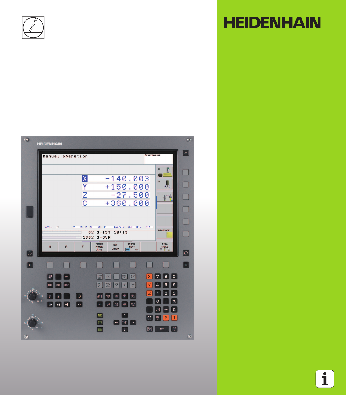
User’s Manual
HEIDENHAIN
Conversational Format
TNC 320
NC Software
340 551-03
English (en)
7/2008
Page 2
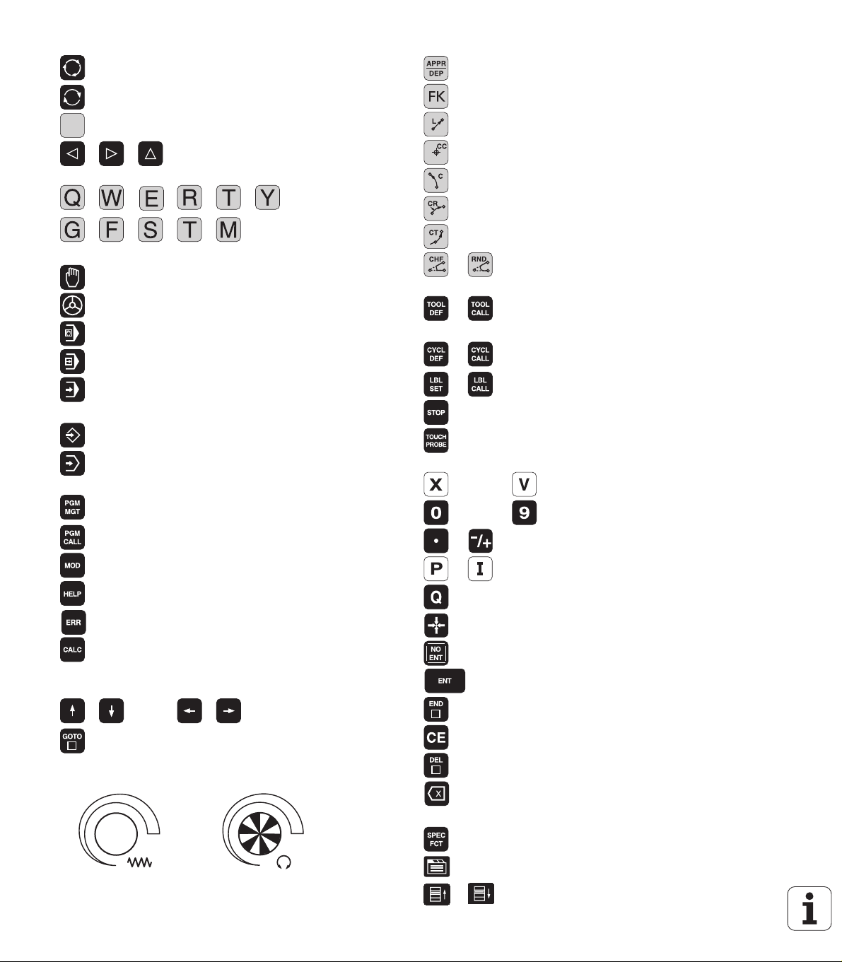
Controls on the visual display unit
Split screen layout
Switch between machining or
programming modes
Soft keys for selecting functions on
screen
Shift between soft-key rows
Typewriter keyboard for entering letters and symbols
File names
Comments
DIN/ISO
programs
Machine operating modes
Manual Operation
Electronic Handwheel
Positioning with Manual Data Input
Program Run, Single Block
Program Run, Full Sequence
Programming modes
Programming and Editing
Test Run
Program/file management, TNC functions
Select or delete programs and files
External data transfer
Define program call, select datum and point tables
Select MOD functions
Display help text for NC error messages
Display all current error messages
Show pocket calculator
Moving the cursor, going directly to blocks, cycles and
parameter functions
Go directly to blocks, cycles and parameter functions
Move highlight
Override control knobs for feed rate/spindle speed
100
0
1
S %
50
50
100
0
1
F %
50
50
Programming path movements
Approach/depart contour
FK free contour programming
Straight line
Circle center/pole for polar coordinates
Circle with center
Circle with radius
Circular arc with tangential connection
Chamfering/Corner rounding
Tool functions
Enter and call tool length and radius
Cycles, subprograms and program section repeats
Define and call cycles
Enter and call labels for subprogramming and
program section repeats
Program stop in a program
Define touch probe cycles
Coordinate axes and numbers: Entering and editing
. . .
. . .
Decimal point / Reverse algebraic sign
Polar coordinate input/
Select coordinate axes or
enter them into the program
Numbers
Incremental dimensions
Q parameter programming/Q parameter status
Save actual position or values from calculator
Skip dialog questions, delete words
Confirm entry and resume dialog
Conclude block and exit entry
Clear numerical entry or TNC error message
Abort dialog, delete program section
Deleting individual characters
Special functions / smarT.NC
Show special functions
No function
Up/down one dialog box or button
Page 3
HEIDENHAIN TNC 320 3
Page 4

Page 5
TNC Model, Software and Features
This manual describes functions and features provided by TNCs as of
the following NC software numbers.
TNC model NC software number
TNC 320 340 551-03
TNC 320 programming station 340 554-03
The machine tool builder adapts the usable features of the TNC to his
machine by setting machine parameters. Some of the functions
described in this manual may therefore not be among the features
provided by the TNC on your machine tool.
TNC functions that may not be available on your machine include:
Probing function for the 3-D touch probe
Rigid tapping
Returning to the contour after an interruption
In addition, the TNC 320 also has options that can be enabled by your
machine tool builder.
Hardware options
Additional axis for 4 axes and open-loop spindle
Additional axis for 5 axes and open-loop spindle
Software option 1
Cylinder surface interpolation (Cycles 27, 28 and 29)
Tilting the machining plane (Cycle 19 and 3-D ROT soft key in the
manual operating mode)
Please contact your machine tool builder to become familiar with the
features of your machine.
Many machine manufacturers, as well as HEIDENHAIN, offer
programming courses for the TNCs. We recommend these courses as
an effective way of improving your programming skill and sharing
information and ideas with other TNC users.
Touch Probe Cycles User’s Manual:
All of the touch probe functions are described in a separate
manual. Please contact HEIDENHAIN if you need a copy of
this User’s Manual. ID: 661 873-10
HEIDENHAIN TNC 320 5
Page 6

Feature content level (upgrade functions)
Along with software options, significant further improvements of the
TNC software are managed via the Feature Content Level upgrade
functions. Functions subject to the FCL are not available simply by
updating the software on your TNC.
All upgrade functions are available to you without
surcharge when you receive a new machine.
Upgrade functions are identified in the manual with FCL n, where n
indicates the sequential number of the feature content level.
You can purchase a code number in order to permanently enable the
FCL functions. For more information, contact your machine tool
builder or HEIDENHAIN.
Intended place of operation
The TNC complies with the limits for a Class A device in accordance
with the specifications in EN 55022, and is intended for use primarily
in industrially-zoned areas.
6
Page 7

New Functions with 340 55x-03
The TNC now also supports datum management with the preset
table (see “Datum management with the preset table,” page 54)
The TNC now also supports the tilting functions on machine tools
with swivel heads and/or tilting tables (see “Tilting the Working
Plane (Software Option 1),” page 60 and see “WORKING PLANE
(Cycle 19, software option 1),” page 346)
Cycle 240 Centering added (See “CENTERING (Cycle 240)” on page
215)
Cycle 208 Helical Finish Milling: The type of milling (climb or up-cut)
can now be selected (See “BORE MILLING (Cycle 208)” on page
231)
Cycle 209 Tapping with Chip Breaking: Fast retraction added (See
“TAPPING WITH CHIP BREAKING (Cycle 209)” on page 237)
Touch Probe Cycles 400 to 405 for automatic measurement and
compensation of workpiece misalignment added (see Touch Probe
Cycles User’s Manual)
Touch Probe Cycles 408 to 419 for automatic datum setting added
(see Touch Probe Cycles User’s Manual)
Touch Probe Cycles 420 to 431 for automatic workpiece
measurement added (see Touch Probe Cycles User’s Manual)
Touch Probe Cycles 480 (30) to 483 (33) for automatic tool
measurement added (see Touch Probe Cycles User’s Manual)
Cycle 19 Working Plane and 3-D ROT (See “Tilting the Working
Plane (Software Option 1)” on page 60)
Backspace dialog key (See page 32)
HEIDENHAIN TNC 320 7
Page 8

Page 9

Contents
Introduction
1
Manual Operation and Setup
Positioning with Manual Data Input
Programming: Fundamentals of File
Management, Programming Aids
Programming: Tools
Programming: Programming Contours
Programming: Miscellaneous Functions
Programming: Cycles
Programming: Subprograms and
Program Section Repeats
Programming: Q Parameters
Test Run and Program Run
MOD Functions
Technical Information
2
3
4
5
6
7
8
9
10
11
12
13
HEIDENHAIN TNC 320 9
Page 10

Page 11

1 Introduction ..... 29
1.1 The TNC 320 ..... 30
Programming: HEIDENHAIN conversational format ..... 30
Compatibility ..... 30
1.2 Visual Display Unit and Keyboard ..... 31
Visual display unit ..... 31
Sets the screen layout ..... 32
Operating panel ..... 32
1.3 Operating Modes ..... 33
Manual operation and electronic handwheel ..... 33
Positioning with Manual Data Input ..... 33
Programming and Editing ..... 34
Test Run ..... 34
Program Run, Full Sequence and Program Run, Single Block ..... 35
1.4 Status Displays ..... 36
“General” status display ..... 36
Additional status displays ..... 38
1.5 Accessories: HEIDENHAIN 3-D Touch Probes and Electronic Handwheels ..... 41
3-D touch probes ..... 41
TT 140 tool touch probe for tool measurement ..... 42
HR electronic handwheels ..... 42
HEIDENHAIN TNC 320 11
Page 12

2 Manual Operation and Setup ..... 43
2.1 Switch-On, Switch-Off ..... 44
Switch-on ..... 44
Switch-off ..... 46
2.2 Moving the Machine Axes ..... 47
Note ..... 47
To traverse with the machine axis direction buttons ..... 47
Incremental jog positioning ..... 48
Traversing with the HR 410 electronic handwheel ..... 49
2.3 Spindle Speed S, Feed Rate F and Miscellaneous Functions M ..... 50
Function ..... 50
Entering values ..... 50
Changing the spindle speed and feed rate ..... 51
2.4 Datum Setting (Without a 3-D Touch Probe) ..... 52
Note ..... 52
Preparation ..... 52
Datum setting with axis keys ..... 53
Datum management with the preset table ..... 54
2.5 Tilting the Working Plane (Software Option 1) ..... 60
Application, function ..... 60
Traversing the reference points in tilted axes ..... 62
Position display in a tilted system ..... 62
Limitations on working with the tilting function ..... 62
Activating manual tilting ..... 63
12
Page 13

3 Positioning with Manual Data Input (MDI) ..... 65
3.1 Programming and Executing Simple Machining Operations ..... 66
Positioning with Manual Data Input (MDI) ..... 66
Protecting and erasing programs in $MDI ..... 69
HEIDENHAIN TNC 320 13
Page 14

4 Programming: Fundamentals of NC, File Management, Programming Aids ..... 71
4.1 Fundamentals ..... 72
Position encoders and reference marks ..... 72
Reference system ..... 72
Reference system on milling machines ..... 73
Designation of the axes on milling machines ..... 73
Polar coordinates ..... 74
Absolute and incremental workpiece positions ..... 75
Setting the datum ..... 76
4.2 File Management: Fundamentals ..... 77
Files ..... 77
Screen keypad ..... 79
Data backup ..... 79
4.3 Working with the File Manager ..... 80
Directories ..... 80
Paths ..... 80
Overview: Functions of the file manager ..... 81
Calling the file manager ..... 82
Selecting drives, directories and files ..... 83
Creating a new directory ..... 84
Copying a single file ..... 85
Copying a directory ..... 85
Choosing one of the last 10 files selected ..... 86
Deleting a file ..... 86
Deleting a directory ..... 86
Marking files ..... 87
Renaming a file ..... 88
File sorting ..... 88
Additional functions ..... 88
Data transfer to or from an external data medium ..... 89
Copying files into another directory ..... 91
The TNC in a network ..... 92
USB devices on the TNC ..... 93
4.4 Creating and Writing Programs ..... 94
Organization of an NC program in HEIDENHAIN conversational format ..... 94
Define the blank: BLK FORM ..... 94
Creating a new part program ..... 95
Programming tool movements in conversational format ..... 97
Actual position capture ..... 98
Editing a program ..... 99
The TNC search function ..... 103
14
Page 15

4.5 Interactive Programming Graphics ..... 105
Generating / Not generating graphics during programming: ..... 105
Generating a graphic for an existing program ..... 105
Block number display ON/OFF ..... 106
Erasing the graphic ..... 106
Magnifying or reducing a detail ..... 106
4.6 Structuring Programs ..... 107
Definition and applications ..... 107
Displaying the program structure window / Changing the active window ..... 107
Inserting a structuring block in the (left) program window ..... 107
Selecting blocks in the program structure window ..... 107
4.7 Adding Comments ..... 108
Function ..... 108
Adding a comment line ..... 108
Functions for editing of the comment ..... 108
4.8 Integrated Pocket Calculator ..... 109
Operation ..... 109
4.9 Error messages ..... 111
Display of errors ..... 111
Open the error window ..... 111
Close the error window ..... 111
Detailed error messages ..... 112
INTERNAL INFO soft key ..... 112
Clearing errors ..... 113
Error log ..... 113
Keystroke log ..... 114
Informational texts ..... 115
Saving service files ..... 115
HEIDENHAIN TNC 320 15
Page 16

5 Programming: Tools ..... 117
5.1 Entering Tool-Related Data ..... 118
Feed rate F ..... 118
Spindle speed S ..... 119
5.2 Tool Data ..... 120
Requirements for tool compensation ..... 120
Tool numbers and tool names ..... 120
Tool length L ..... 120
Tool radius R ..... 121
Delta values for lengths and radii ..... 121
Entering tool data into the program ..... 121
Entering tool data in the table ..... 122
Pocket table for tool changer ..... 128
Calling tool data ..... 131
5.3 Tool Compensation ..... 133
Introduction ..... 133
Tool length compensation ..... 133
Tool radius compensation ..... 134
16
Page 17

6 Programming: Programming Contours ..... 137
6.1 Tool Movements ..... 138
Path functions ..... 138
FK free contour programming ..... 138
Miscellaneous functions M ..... 138
Subprograms and program section repeats ..... 138
Programming with Q parameters ..... 138
6.2 Fundamentals of Path Functions ..... 139
Programming tool movements for workpiece machining ..... 139
6.3 Contour Approach and Departure ..... 142
Overview: Types of paths for contour approach and departure ..... 142
Important positions for approach and departure ..... 143
Approaching on a straight line with tangential connection: APPR LT ..... 145
Approaching on a straight line perpendicular to the first contour point: APPR LN ..... 145
Approaching on a circular path with tangential connection: APPR CT ..... 146
Approaching on a circular arc with tangential connection from a straight line to the contour: APPR LCT ..... 147
Departing on a straight line with tangential connection: DEP LT ..... 148
Departing on a straight line perpendicular to the last contour point: DEP LN ..... 148
Departure on a circular path with tangential connection: DEP CT ..... 149
Departing on a circular arc tangentially connecting the contour and a straight line: DEP LCT ..... 149
6.4 Path Contours—Cartesian Coordinates ..... 150
Overview of path functions ..... 150
Straight line L ..... 151
Inserting a chamfer CHF between two straight lines ..... 152
Corner rounding RND ..... 153
Circle center CC ..... 154
Circular path C around circle center CC ..... 155
Circular path CR with defined radius ..... 156
Circular path CT with tangential connection ..... 158
6.5 Path Contours—Polar Coordinates ..... 163
Overview ..... 163
Polar coordinate origin: Pole CC ..... 164
Straight line LP ..... 164
Circular path CP around pole CC ..... 165
Circular path CTP with tangential connection ..... 165
Helical interpolation ..... 166
HEIDENHAIN TNC 320 17
Page 18

6.6 Path Contours—FK Free Contour Programming ..... 170
Fundamentals ..... 170
Graphics during FK programming ..... 171
Initiating the FK dialog ..... 173
Pole for FK programming ..... 173
Free programming of straight lines ..... 174
Free programming of circular arcs ..... 174
Input possibilities ..... 175
Auxiliary points ..... 178
Relative data ..... 179
18
Page 19

7 Programming: Miscellaneous Functions ..... 187
7.1 Entering Miscellaneous Functions M and STOP ..... 188
Fundamentals ..... 188
7.2 Miscellaneous Functions for Program Run Control, Spindle and Coolant ..... 190
Overview ..... 190
7.3 Miscellaneous Functions for Coordinate Data ..... 191
Programming machine-referenced coordinates: M91/M92 ..... 191
Moving to positions in a non-tilted coordinate system with a tilted working plane: M130 ..... 193
7.4 Miscellaneous Functions for Contouring Behavior ..... 194
Machining small contour steps: M97 ..... 194
Machining open contours: M98 ..... 196
Feed rate for circular arcs: M109/M110/M111 ..... 197
Calculating the radius-compensated path in advance (LOOK AHEAD): M120 ..... 198
Superimposing handwheel positioning during program run: M118 ..... 200
Retraction from the contour in the tool-axis direction: M140 ..... 201
Suppressing touch probe monitoring: M141 ..... 202
Delete basic rotation: M143 ..... 202
Automatically retract tool from the contour at an NC stop: M148 ..... 203
7.5 Miscellaneous Functions for Rotary Axes ..... 204
Feed rate in mm/min on rotary axes A, B, C: M116 (software option 1) ..... 204
Shorter-path traverse of rotary axes: M126 ..... 205
Reducing display of a rotary axis to a value less than 360°: M94 ..... 206
HEIDENHAIN TNC 320 19
Page 20

8 Programming: Cycles ..... 207
8.1 Working with Cycles ..... 208
Machine-specific cycles ..... 208
Defining a cycle using soft keys ..... 209
Defining a cycle using the GOTO function ..... 209
Cycles Overview ..... 210
Calling cycles ..... 211
8.2 Cycles for Drilling, Tapping and Thread Milling ..... 213
Overview ..... 213
CENTERING (Cycle 240) ..... 215
DRILLING (Cycle 200) ..... 217
REAMING (Cycle 201) ..... 219
BORING (Cycle 202) ..... 221
UNIVERSAL DRILLING (Cycle 203) ..... 223
BACK BORING (Cycle 204) ..... 225
UNIVERSAL PECKING (Cycle 205) ..... 228
BORE MILLING (Cycle 208) ..... 231
TAPPING NEW with floating tap holder (Cycle 206) ..... 233
RIGID TAPPING without a floating tap holder NEW (Cycle 207) ..... 235
TAPPING WITH CHIP BREAKING (Cycle 209) ..... 237
Fundamentals of thread milling ..... 240
THREAD MILLING (Cycle 262) ..... 242
THREAD MILLING/COUNTERSINKING (Cycle 263) ..... 244
THREAD DRILLING/MILLING (Cycle 264) ..... 248
HELICAL THREAD DRILLING/MILLING (Cycle 265) ..... 252
OUTSIDE THREAD MILLING (Cycle 267) ..... 256
8.3 Cycles for Milling Pockets, Studs and Slots ..... 262
Overview ..... 262
POCKET MILLING (Cycle 4) ..... 263
POCKET FINISHING (Cycle 212) ..... 265
STUD FINISHING (Cycle 213) ..... 267
CIRCULAR POCKET (Cycle 5) ..... 269
CIRCULAR POCKET FINISHING (Cycle 214) ..... 271
CIRCULAR STUD FINISHING (Cycle 215) ..... 273
SLOT (oblong hole) with reciprocating plunge-cut (Cycle 210) ..... 275
CIRCULAR SLOT (oblong hole) with reciprocating plunge-cut (Cycle 211) ..... 278
8.4 Cycles for Machining Point Patterns ..... 284
Overview ..... 284
CIRCULAR PATTERN (Cycle 220) ..... 285
LINEAR PATTERN (Cycle 221) ..... 287
20
Page 21

8.5 SL Cycles ..... 291
Fundamentals ..... 291
Overview of SL cycles ..... 293
CONTOUR GEOMETRY (Cycle 14) ..... 294
Overlapping contours ..... 294
CONTOUR DATA (Cycle 20) ..... 297
PILOT DRILLING (Cycle 21) ..... 298
ROUGH-OUT (Cycle 22) ..... 299
FLOOR FINISHING (Cycle 23) ..... 301
SIDE FINISHING (Cycle 24) ..... 302
CONTOUR TRAIN (Cycle 25) ..... 303
Program defaults for cylindrical surface machining cycles (software option 1!) ..... 305
CYLINDER SURFACE (Cycle 27, software option 1) ..... 306
CYLINDER SURFACE slot milling (Cycle 28, software option 1) ..... 308
CYLINDER SURFACE ridge milling (Cycle 29, software option 1) ..... 310
8.6 Cycles for Multipass Milling ..... 321
Overview ..... 321
MULTIPASS MILLING (Cycle 230) ..... 322
RULED SURFACE (Cycle 231) ..... 324
FACE MILLING (Cycle 232) ..... 327
8.7 Coordinate Transformation Cycles ..... 334
Overview ..... 334
Effect of coordinate transformations ..... 335
DATUM SHIFT (Cycle 7) ..... 336
DATUM SHIFT with datum tables (Cycle 7) ..... 337
DATUM SETTING (Cycle 247) ..... 340
MIRROR IMAGE (Cycle 8) ..... 341
ROTATION (Cycle 10) ..... 343
SCALING FACTOR (Cycle 11) ..... 344
AXIS-SPECIFIC SCALING (Cycle 26) ..... 345
WORKING PLANE (Cycle 19, software option 1) ..... 346
8.8 Special Cycles ..... 354
DWELL TIME (Cycle 9) ..... 354
PROGRAM CALL (Cycle 12) ..... 355
ORIENTED SPINDLE STOP (Cycle 13) ..... 356
TOLERANCE (Cycle 32) ..... 357
HEIDENHAIN TNC 320 21
Page 22

9 Programming: Subprograms and Program Section Repeats ..... 361
9.1 Labeling Subprograms and Program Section Repeats ..... 362
Labels ..... 362
9.2 Subprograms ..... 363
Operating sequence ..... 363
Programming notes ..... 363
Programming a subprogram ..... 363
Calling a subprogram ..... 363
9.3 Program Section Repeats ..... 364
Label LBL ..... 364
Operating sequence ..... 364
Programming notes ..... 364
Programming a program section repeat ..... 364
Calling a program section repeat ..... 364
9.4 Separate Program as Subprogram ..... 365
Operating sequence ..... 365
Programming notes ..... 365
Calling any program as a subprogram ..... 365
9.5 Nesting ..... 366
Types of nesting ..... 366
Nesting depth ..... 366
Subprogram within a subprogram ..... 366
Repeating program section repeats ..... 368
Repeating a subprogram ..... 369
9.6 Programming Examples ..... 370
22
Page 23

10 Programming: Q-Parameters ..... 377
10.1 Principle and Overview ..... 378
Programming notes ..... 379
Calling Q parameter functions ..... 379
10.2 Part Families—Q Parameters in Place of Numerical Values ..... 380
Example NC blocks ..... 380
Example ..... 380
10.3 Describing Contours through Mathematical Operations ..... 381
Function ..... 381
Overview ..... 381
Programming fundamental operations ..... 382
10.4 Trigonometric Functions ..... 383
Definitions ..... 383
Programming trigonometric functions ..... 384
10.5 Calculating Circles ..... 385
Function ..... 385
10.6 If-Then Decisions with Q Parameters ..... 386
Function ..... 386
Unconditional jumps ..... 386
Programming If-Then decisions ..... 386
Abbreviations used: ..... 387
10.7 Checking and Changing Q Parameters ..... 388
Procedure ..... 388
10.8 Additional Functions ..... 389
Overview ..... 389
FN14: ERROR: Displaying error messages ..... 390
FN 16: F-PRINT: Formatted output of text and Q parameter values ..... 394
FN18: SYS-DATUM READ Read system data ..... 399
FN19: PLC: Transferring values to the PLC ..... 407
FN20: WAIT FOR: NC and PLC synchronization ..... 408
FN29: PLC: Transferring values to the PLC ..... 410
FN37:EXPORT ..... 410
10.9 Accessing Tables with SQL Commands ..... 411
Introduction ..... 411
A Transaction ..... 412
Programming SQL commands ..... 414
Overview of the soft keys ..... 414
SQL BIND ..... 415
SQL SELECT ..... 416
SQL FETCH ..... 419
SQL UPDATE ..... 420
SQL INSERT ..... 420
SQL COMMIT ..... 421
SQL ROLLBACK ..... 421
HEIDENHAIN TNC 320 23
Page 24

10.10 Entering Formulas Directly ..... 422
Entering formulas ..... 422
Rules for formulas ..... 424
Programming example ..... 425
10.11 String Parameters ..... 426
String processing functions ..... 426
Assigning string parameters ..... 427
Chain-linking string parameters ..... 427
Converting a numerical value to a string parameter ..... 428
Copying a substring from a string parameter ..... 429
Converting a string parameter to a numerical value ..... 430
Checking a string parameter ..... 431
Finding the length of a string parameter ..... 432
Comparing alphabetic priority ..... 433
10.12 Preassigned Q Parameters ..... 434
Values from the PLC: Q100 to Q107 ..... 434
Active tool radius: Q108 ..... 434
Tool axis: Q109 ..... 434
Spindle status: Q110 ..... 435
Coolant on/off: Q111 ..... 435
Overlap factor: Q112 ..... 435
Unit of measurement for dimensions in the program: Q113 ..... 435
Tool length: Q114 ..... 435
Coordinates after probing during program run ..... 436
Deviation between actual value and nominal value during automatic tool measurement with the TT 130 ..... 437
Tilting the working plane with mathematical angles: rotary axis coordinates calculated by the TNC ..... 437
Measurement results from touch probe cycles (see also User’s Manual for Touch Probe Cycles) ..... 438
10.13 Programming Examples ..... 440
24
Page 25

11 Test Run and Program Run ..... 447
11.1 Graphics ..... 448
Function ..... 448
Overview of display modes ..... 449
Plan view ..... 449
Projection in 3 planes ..... 450
3-D view ..... 451
Magnifying details ..... 452
Repeating graphic simulation ..... 453
Measuring the machining time ..... 453
11.2 Showing the Workpiece in the Working Space ..... 454
Function ..... 454
11.3 Functions for Program Display ..... 455
Overview ..... 455
11.4 Test Run ..... 456
Function ..... 456
11.5 Program Run ..... 458
Function ..... 458
Run a part program ..... 459
Interrupting machining ..... 460
Moving the machine axes during an interruption ..... 460
Resuming program run after an interruption ..... 461
Mid-program startup (block scan) ..... 462
Returning to the contour ..... 463
11.6 Automatic Program Start ..... 464
Function ..... 464
11.7 Optional Block Skip ..... 465
Function ..... 465
Inserting the “/” character ..... 465
Erasing the “/” character ..... 465
11.8 Optional Program-Run Interruption ..... 466
Function ..... 466
HEIDENHAIN TNC 320 25
Page 26

12 MOD Functions ..... 467
12.1 Selecting MOD Functions ..... 468
Selecting the MOD functions ..... 468
Changing the settings ..... 468
Exiting the MOD functions ..... 468
Overview of MOD functions ..... 469
12.2 Software Numbers ..... 470
Function ..... 470
12.3 Position Display Types ..... 471
Function ..... 471
12.4 Unit of Measurement ..... 472
Function ..... 472
12.5 Displaying Operating Times ..... 473
Function ..... 473
12.6 Entering Code Numbers ..... 474
Function ..... 474
12.7 Setting the Data Interfaces ..... 475
Serial interface on the TNC 320 ..... 475
Function ..... 475
Setting the RS-232 interface ..... 475
Setting the baud rate (baudRate) ..... 475
Set the protocol (protocol) ..... 475
Set the data bits (dataBits) ..... 476
Parity check (parity) ..... 476
Setting the stop bits (stopBits) ..... 476
Setting the handshake (flowControl) ..... 476
Settings for data transfer with the TNCserver PC software ..... 477
Setting the operating mode of the external device (fileSystem) ..... 477
Software for data transfer ..... 478
12.8 Ethernet Interface ..... 480
Introduction ..... 480
Connection possibilities ..... 480
Connecting the control to the network ..... 480
26
Page 27

13 Tables and Overviews ..... 485
13.1 Machine-Specific User Parameters ..... 486
Function ..... 486
13.2 Pin Layout and Connecting Cable for the Data Interfaces ..... 494
RS-232-C/V.24 interface for HEIDEHAIN devices ..... 494
Non-HEIDENHAIN devices ..... 495
Ethernet interface RJ45 socket ..... 495
13.3 Technical Information ..... 496
13.4 Exchanging the Buffer Battery ..... 501
HEIDENHAIN TNC 320 27
Page 28

Page 29

Introduction
Page 30
1.1 The TNC 320
HEIDENHAIN TNC controls are workshop-oriented contouring
controls that enable you to program conventional machining
operations right at the machine in an easy-to-use conversational
programming language. The TNC 320 is designed for milling and
drilling machine tools with up to 4 axes (optionally 5 axes). Instead of
the fourth or fifth axis, you can also change the angular position of the
spindle under program control.
Keyboard and screen layout are clearly arranged in such a way that the
1.1 The TNC 320
functions are fast and easy to use.
Programming: HEIDENHAIN conversational format
HEIDENHAIN conversational programming is an especially easy
method of writing programs. Interactive graphics illustrate the
individual machining steps for programming the contour. If a
production drawing is not dimensioned for NC, the HEIDENHAIN FK
free contour programming performs the necessary calculations
automatically. Workpiece machining can be graphically simulated
either during or before actual machining.
You can also enter and test one program while the control is running
another.
Compatibility
The scope of functions of the TNC 320 does not correspond to that of
the TNC 4xx and iTNC 530 series of controls. Therefore, machining
programs created on HEIDENHAIN contouring controls (starting from
the TNC 150 B) may not always run on the TNC 320. If NC blocks
contain invalid elements, the TNC will mark them as ERROR blocks
during download.
30 1 Introduction
Page 31

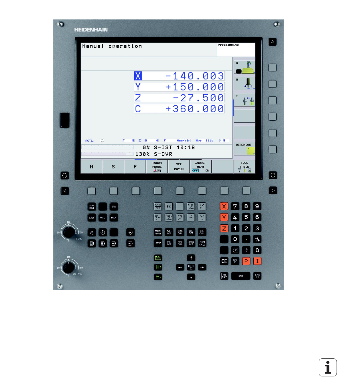
1.2 Visual Display Unit and
Keyboard
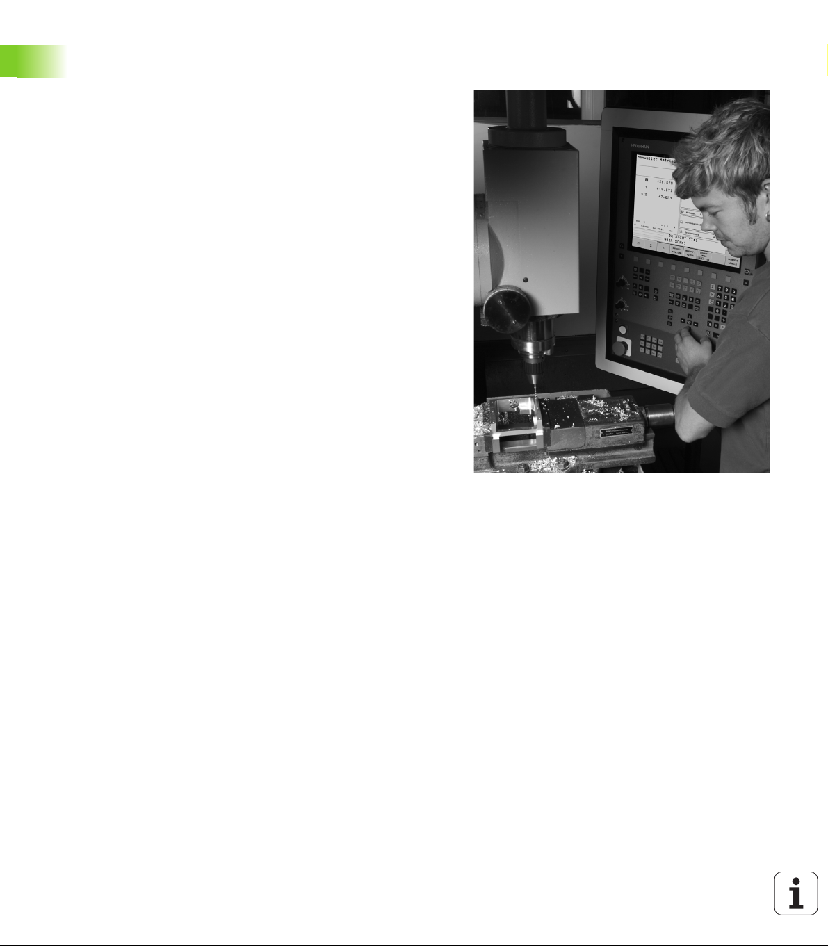
Visual display unit
The TNC is delivered with a 15-inch TFT color flat-panel display (see
figure at top right).
1 Header
When the TNC is on, the selected operating modes are shown in
the screen header: the machining mode at the left and the
programming mode at right. The currently active mode is
displayed in the larger box, where the dialog prompts and TNC
messages also appear (unless the TNC is showing only graphics).
2 Soft keys
In the footer the TNC indicates additional functions in a soft-key
row. You can select these functions by pressing the keys
immediately below them. The lines immediately above the softkey row indicate the number of soft-key rows that can be called
with the black arrow keys to the right and left. The active soft-key
row is indicated by brightened bar.
3 Soft-key selection keys
4 Shift between soft-key rows
5 Sets the screen layout
6 Shift key for switchover between machining and programming
modes
7 Soft-key selection keys for machine tool builders
8 Switches soft-key rows for machine tool builders
9 USB connection
1
1
9
1
5 1
4
2
3
1
8
7
6
4
1.2 Visual Display Unit and Keyboard
HEIDENHAIN TNC 320 31
Page 32

Sets the screen layout
You select the screen layout yourself: In the programming mode of
operation, for example, you can have the TNC show program blocks in
the left window while the right window displays programming
graphics. You could also display status information in the right window
instead of the graphics, or display only program blocks in one large
window. The available screen windows depend on the selected
operating mode.
To change the screen layout:
Press the SPLIT SCREEN key: The soft-key row
shows the available layout options (See “Operating
Modes,” page 33).
Select the desired screen layout.
Operating panel
The TNC 320 is delivered with an integrated keyboard. The figure at
right shows the controls and displays of the keyboard:
1.2 Visual Display Unit and Keyboard
1 File management
Online calculator
MOD function
HELP function
2 Programming modes
3 Machine operating modes
4 Initiation of programming dialog
5 Arrow keys and GOTO jump command
6 Numerical input and axis selection
7 Navigation keys
The functions of the individual keys are described on the inside front
cover.
Machine panel buttons, e.g. NC START or NC STOP, are
described in the manual for your machine tool.
1
4
1
6
2
3
1
5
77
32 1 Introduction
Page 33

1.3 Operating Modes
Manual operation and electronic handwheel
The Manual Operation mode is required for setting up the machine
tool. In this operating mode, you can position the machine axes
manually or by increments and set the datums.
The Electronic Handwheel mode of operation allows you to move the
machine axes manually with the HR electronic handwheel.
Soft keys for selecting the screen layout (select as described
previously)
Window Soft key
Positions
Left: positions, right: status display
Positioning with Manual Data Input
This mode of operation is used for programming simple traversing
movements, such as for face milling or pre-positioning.
Soft keys for selecting the screen layout
Window Soft key
Program
Left: program blocks, right: status display
1.3 Operating Modes
HEIDENHAIN TNC 320 33
Page 34
Programming and Editing
In this mode of operation you can write your part programs. The FK
free programming feature, the various cycles and the Q parameter
functions help you with programming and add necessary information.
If desired, you can have the programming graphics show the individual
steps.
Soft keys for selecting the screen layout
Window Soft key
Program
Left: program blocks, right: program structure
1.3 Operating Modes
Left: program blocks, right: graphics
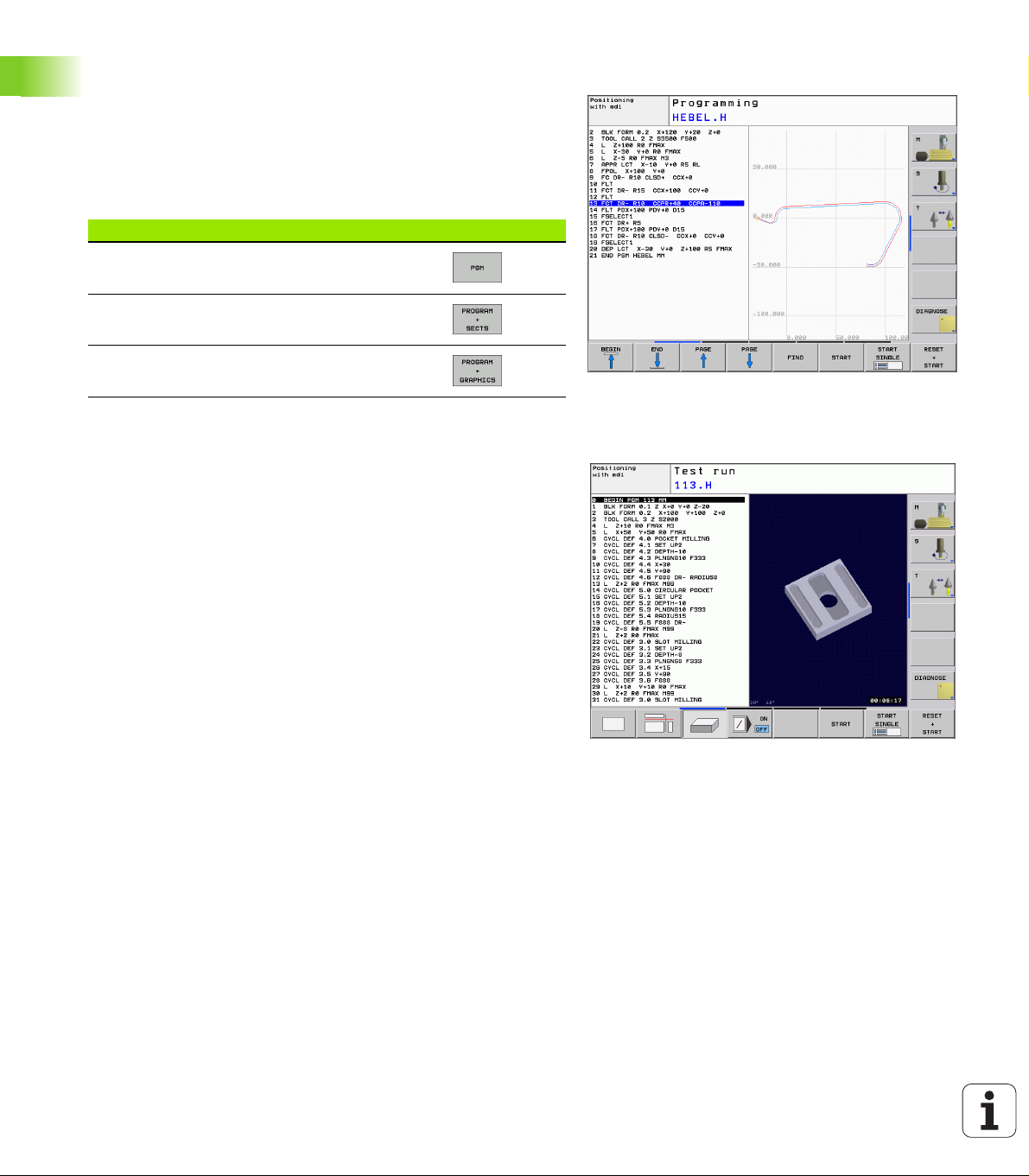
Test Run
In the Test Run mode of operation, the TNC checks programs and
program sections for errors, such as geometrical incompatibilities,
missing or incorrect data within the program or violations of the work
space. This simulation is supported graphically in different display
modes.
Soft keys for selecting the screen layout: See “Program Run, Full
Sequence and Program Run, Single Block,” page 35.
34 1 Introduction
Page 35
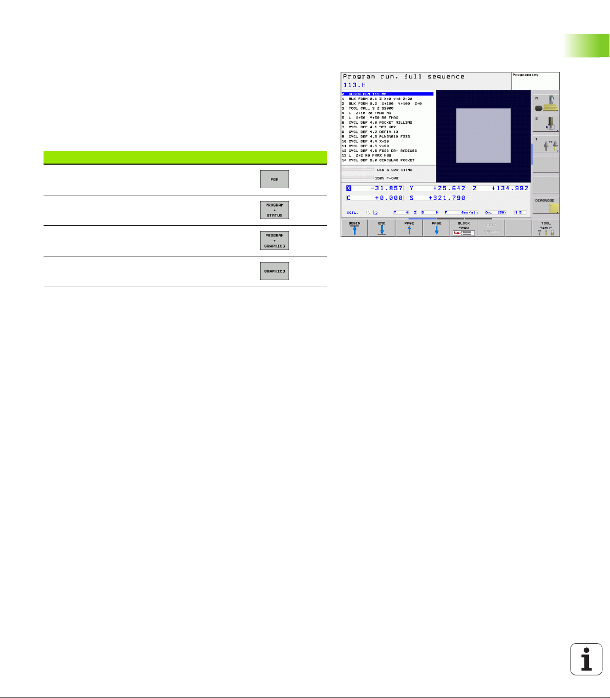
Program Run, Full Sequence and Program Run, Single Block
In the Program Run, Full Sequence mode of operation the TNC
executes a part program continuously to its end or to a manual or
programmed stop. You can resume program run after an interruption.
In the Program Run, Single Block mode of operation you execute each
block separately by pressing the machine START button.
Soft keys for selecting the screen layout
Window Soft key
Program
Left: program blocks, right: status
Left: program, right: graphics
Graphics
1.3 Operating Modes
HEIDENHAIN TNC 320 35
Page 36
1.4 Status Displays
“General” status display
The status display in the lower part of the screen informs you of the
current state of the machine tool. It is displayed automatically in the
following modes of operation:
Program Run, Single Block and Program Run, Full Sequence, except
if the screen layout is set to display graphics only, and
Positioning with Manual Data Input (MDI).
In the Manual mode and Electronic Handwheel mode the status
1.4 Status Displays
display appears in the large window.
36 1 Introduction
Page 37

Information in the status display
ACTL
Symbol Meaning
.
Actual or nominal coordinates of the current position.
X Y Z
F S M
Machine axes; the TNC displays auxiliary axes in
lower-case letters. The sequence and quantity of
displayed axes is determined by the machine tool
builder. Refer to your machine manual for more
information.
Tool number T
1.4 Status Displays
The displayed feed rate in inches corresponds to one
tenth of the effective value. Spindle speed S, feed
rate F and active M functions.
Axis locked.
Override setting in percent.
Axis can be moved with the handwheel.
Axes are moving under a basic rotation.
Axes are moving in a tilted working plane.
No active program.
Program run started.
Stops the program run.
Program run is being aborted.
HEIDENHAIN TNC 320 37
Page 38

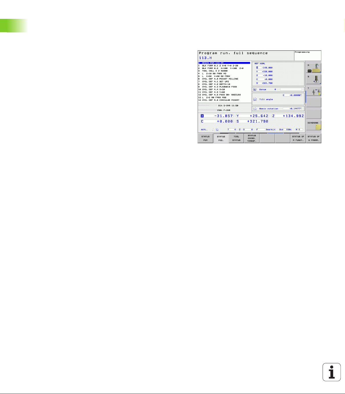
Additional status displays
The additional status displays contain detailed information on the
program run. They can be called in all operating modes except for the
Programming mode.
To switch on the additional status display:
Call the soft-key row for screen layout.
1.4 Status Displays
To select an additional status display:
You can choose between several additional status displays with the
following soft keys:
Select the layout option for the additional status
display.
Shift the soft-key rows until the STATUS soft keys
appear.
Select the desired additional status display, e.g.
general program information.
38 1 Introduction
Page 39

General program information
Soft key Meaning
Name of the active main program
Active programs
Active machining cycle
Circle center CC (pole)
Machining time
Dwell time counter
Positions and coordinates
Soft key Meaning
Type of position display, e.g. actual position
Number of the active datum from the preset table.
Tilt angle of the working plane
Angle of a basic rotation
1.4 Status Displays
Information on tools
Soft key Meaning
Display of tool: Tool number
Tool axis
Tool lengths and radii
Oversizes (delta values) from TOOL CALL (PGM) and
the tool table (TAB)
Tool life, maximum tool life (TIME 1) and maximum
tool life for TOOL CALL (TIME 2)
Display of the active tool and the (next) replacement
tool
HEIDENHAIN TNC 320 39
Page 40

Coordinate transformation
Soft key Meaning
Program name
Active datum shift (Cycle 7)
Mirrored axes (Cycle 8)
Active rotation angle (Cycle 10)
Active scaling factor(s) (Cycles 11 / 26)
1.4 Status Displays
See “Coordinate Transformation Cycles” on page 334.
Active miscellaneous functions M
Soft key Meaning
List of the active M functions with fixed meaning
List of the active M functions that are adapted by your
machine manufacturer
Status of Q parameters
Soft key Meaning
List of Q parameters defined with the Q PARAM LIST
soft key
40 1 Introduction
Page 41

1.5 Accessories: HEIDENHAIN 3-D
Touch Probes and Electronic
Handwheels
3-D touch probes
With the various HEIDENHAIN 3-D touch probe systems you can:
Automatically align workpieces
Quickly and precisely set datums
Measure the workpiece during program run
Measure and inspect tools
All of the touch probe functions are described in a
separate manual. Please contact HEIDENHAIN if you
require a copy of this User’s Manual. ID 661 873-10.
TS 220, TS 440 and TS 640 touch trigger probes
These touch probes are particularly effective for automatic workpiece
alignment, datum setting and workpiece measurement. The TS 220
transmits the triggering signals to the TNC via cable and may be a
more economical alternative.
The TS 440, TS 444, TS 640 and TS 740 (see figures at right) feature
infrared transmission of the triggering signal to the TNC. This makes
them highly convenient for use on machines with automatic tool
changers.
Principle of operation: HEIDENHAIN triggering touch probes feature a
wear resisting optical switch that generates an electrical signal as
soon as the stylus is deflected. This signal is transmitted to the TNC,
which stores the current position of the stylus as an actual value.
HEIDENHAIN TNC 320 41
1.5 Accessories: HEIDENHAIN 3-D Touch Probes and Electronic Handwheels
Page 42

TT 140 tool touch probe for tool measurement
The TT 140 is a triggering 3-D touch probe for tool measurement and
inspection. Your TNC provides three cycles for this touch probe with
which you can measure the tool length and radius automatically either
with the spindle rotating or stopped. The TT 140 features a particularly
rugged design and a high degree of protection, which make it
insensitive to coolants and swarf. The triggering signal is generated by
a wear-resistant and highly reliable optical switch.
HR electronic handwheels
Electronic handwheels facilitate moving the axis slides precisely by
hand. A wide range of traverses per handwheel revolution is available.
Apart from the HR 130 and HR 150 integral handwheels,
HEIDENHAIN also offers the HR 410 portable handwheel.
1.5 Accessories: HEIDENHAIN 3-D Touch Probes and Electronic Handwheels
42 1 Introduction
Page 43

Manual Operation and Setup
Page 44

2.1 Switch-On, Switch-Off
Switch-on
Switch-on and crossing the reference points can vary
depending on the machine tool. Refer to your machine
manual.
Switch on the power supply for control and machine. The TNC then
displays the following dialog:
SYSTEM STARTUP
TNC is started
POWER INTERRUPTED
2.1 Switch-On, Switch-Off
TNC message that the power was interrupted—clear
the message.
CONVERT PLC PROGRAM
The PLC program of the TNC is automatically compiled.
RELAY EXT. DC VOLTAGE MISSING
Switch on external dc voltage. The TNC checks the
functioning of the EMERGENCY STOP circuit.
MANUAL OPERATION
TRAVERSE REFERENCE POINTS
Cross the reference points manually in the displayed
sequence: For each axis press the machine START
button, or
Cross the reference points in any sequence: Press
and hold the machine axis direction button for each
axis until the reference point has been traversed.
If your machine is equipped with absolute encoders, you
can leave out crossing the reference marks. In such a
case, the TNC is ready for operation immediately after the
machine control voltage is switched on.
44 2 Manual Operation and Setup
Page 45

The TNC is now ready for operation in the Manual Operation mode.
The reference points need only be crossed if the machine
axes are to be moved. If you intend only to write, edit or
test programs, you can select the Programming or Test
Run modes of operation immediately after switching on
the control voltage.
You can cross the reference points later by pressing the
PASS OVER REFERENCE soft key in the Manual
Operation mode.
Crossing the reference point in a tilted working plane
The TNC automatically activates the tilted working plane if this
function was enabled when the control was switched off. Then the
TNC moves the axes in the tilted coordinate system when an axisdirection key is pressed. Position the tool in such a way that a collision
is excluded during the subsequent crossing of the reference points. To
cross the reference points you have to deactivate the "Tilt Working
Plane" function, See “Activating manual tilting,” page 63.
Make sure that the angle values entered in the menu for
tilting the working plane match the actual angles of the
tilted axis.
Deactivate the "Tilt Working Plane" function before you
cross the reference points. Take care that there is no
collision. Retract the tool from the current position first, if
necessary.
2.1 Switch-On, Switch-Off
If you use this function, then for non-absolute encoders
you must confirm the positions of the rotary axes, which
the TNC displays in a pop-up window. The position
displayed is the last active position of the rotary axes
before switch-off.
HEIDENHAIN TNC 320 45
Page 46

Switch-off
To prevent data being lost at switch-off, you need to shut down the
operating system of the TNC as follows:
Select the Manual Operation mode.
Select the function for shutting down, confirm again
with the YES soft key.
When the TNC displays the message NOW IT IS SAFE
TO TURN POWER OFF in a superimposed window, you
may cut off the power supply to the TNC.
Inappropriate switch-off of the TNC can lead to data loss.
Remember that pressing the END key after the control
has been shut down restarts the control. Switch-off
during a restart can also result in data loss!
2.1 Switch-On, Switch-Off
46 2 Manual Operation and Setup
Page 47

2.2 Moving the Machine Axes
Note
Traversing with the machine axis direction buttons can
vary depending on the machine tool. The machine tool
manual provides further information.
To traverse with the machine axis direction buttons
Select the Manual Operation mode.
Press the machine axis direction button and hold it as
long as you wish the axis to move, or
Move the axis continuously: Press and hold the
machine axis direction button, then press the
and
machine START button.
2.2 Moving the Machine Axes
To stop the axis, press the machine STOP button.
You can move several axes at a time with these two methods. You can
change the feed rate at which the axes are traversed with the F soft
key, See “Spindle Speed S, Feed Rate F and Miscellaneous Functions
M,” page 50.
HEIDENHAIN TNC 320 47
Page 48

Incremental jog positioning
With incremental jog positioning you can move a machine axis by a
preset distance.
Select the Manual Operation or Electronic Handwheel
mode.
Z
Select incremental jog positioning: Switch the
INCREMENT soft key to ON.
LINEAR AXES:
Enter the jog increment in mm, e.g. 8 mm, and press
the CONFIRM VALUE soft key.
2.2 Moving the Machine Axes
To deactivate the function, press the Switch off soft key.
Finish the entry with the OK soft key.
Press the machine axis direction button as often as
desired
8
8
8
X
16
48 2 Manual Operation and Setup
Page 49

Traversing with the HR 410 electronic handwheel
The portable HR 410 handwheel is equipped with two permissive
buttons. The permissive buttons are located below the star grip.
You can only move the machine axes when a permissive button is
depressed (machine-dependent function).
The HR 410 handwheel features the following operating elements:
1 EMERGENCY STOP button
2 Handwheel
3 Permissive buttons
4 Axis address keys
5 Actual-position-capture key
6 Keys for defining the feed rate (slow, medium, fast; the feed rates
are set by the machine tool builder)
7 Direction in which the TNC moves the selected axis
8 Machine function (set by the machine tool builder)
The red indicator lights show the axis and feed rate you have selected.
It is also possible to move the machine axes with the handwheel
during program run if M118 is active.
Procedure for traversing
Select the Electronic Handwheel operating mode.
1
2
3
4
6
8
4
5
7
2.2 Moving the Machine Axes
Press and hold a permissive button.
Select the axis.
Select the feed rate.
Move the active axis in the positive or negative
or
HEIDENHAIN TNC 320 49
direction.
Page 50

2.3 Spindle Speed S, Feed Rate F
and Miscellaneous Functions M
Function
In the Manual Operation and Electronic Handwheel operating modes,
you can enter the spindle speed S, feed rate F and the miscellaneous
functions M with soft keys. The miscellaneous functions are
described in Chapter 7 “Programming: Miscellaneous Functions.”
The machine tool builder determines which
miscellaneous functions M are available on your control
and what effects they have.
Entering values
Spindle speed S, miscellaneous function M
To enter the spindle speed, press the S soft key.
SPINDLE SPEED S =
1000
The spindle speed S with the entered rpm is started with a
miscellaneous function M. Proceed in the same way to enter a
miscellaneous function M.
Feed rate F
After entering a feed rate F, you must confirm your entry with the OK
key instead of the machine START button.
The following is valid for feed rate F:
If you enter F=0, then the lowest feed rate from the machine
parameter minFeed is effective
If the feed rate entered exceeds the value defined in the machine
parameter maxFeed, then the parameter value is effective.
F is not lost during a power interruption
2.3 Spindle Speed S, Feed Rate F and Miscellaneous Functions M
Enter the desired spindle speed and confirm your
entry with the machine START button.
50 2 Manual Operation and Setup
Page 51

Changing the spindle speed and feed rate
With the override knobs you can vary the spindle speed S and feed
rate F from 0% to 150% of the set value.
The override knob for spindle speed is only functional on
machines with infinitely variable spindle drive.
HEIDENHAIN TNC 320 51
2.3 Spindle Speed S, Feed Rate F and Miscellaneous Functions M
Page 52

2.4 Datum Setting (Without a 3-D
Touch Probe)
Note
For datum setting with a 3-D touch probe, refer to the
Touch Probe Cycles Manual.
You fix a datum by setting the TNC position display to the coordinates
of a known position on the workpiece.
Preparation
Clamp and align the workpiece.
Insert the zero tool with known radius into the spindle.
Ensure that the TNC is showing the actual position values.
2.4 Datum Setting (Without a 3-D Touch Probe)
52 2 Manual Operation and Setup
Page 53

Datum setting with axis keys
Fragile workpiece?
If the workpiece surface must not be scratched, you can
lay a metal shim of known thickness d on it. Then enter a
tool axis datum value that is larger than the desired datum
by the value d.
Select the Manual Operation mode.
Move the tool slowly until it touches (scratches) the
workpiece surface.
Select an axis (all axes can also be selected via the
ASCII keyboard).
DATUM SET Z=
Zero tool in spindle axis: Set the display to a known
workpiece position (here, 0) or enter the thickness d
of the shim. In the tool axis, offset the tool radius.
Repeat the process for the remaining axes.
If you are using a preset tool, set the display of the tool axis to the
length L of the tool or enter the sum Z=L+d
Y
Z
Y
-R
-R
X
X
2.4 Datum Setting (Without a 3-D Touch Probe)
The TNC automatically saves the datum set with the axis
keys in line 0 of the preset table.
HEIDENHAIN TNC 320 53
Page 54

Datum management with the preset table
You should definitely use the preset table if:
Your machine is equipped with rotary axes (tilting table
or swivel head) and you work with the function for tilting
the working plane
Up to now you have been working with older TNC
controls with REF-based datum tables
You wish to machine identical workpieces that are
differently aligned
The preset table can contain any number of lines (datums).
To optimize the file size and the processing speed, you
should use only as many lines as you need for datum
management.
For safety reasons, new lines can be inserted only at the
end of the preset table.
Saving the datums in the preset table
The preset table has the name PRESET.PR, and is saved in the directory
TNC:\table. PRESET.PR is editable only in the Manual Operation and
Electronic Handwheel modes. In the Programming mode you can only
read the table, not edit it.
It is permitted to copy the preset table into another directory (for data
backup).
Never change the number of lines in the copied tables! That could
cause problems when you want to reactivate the table.
To activate the preset table copied to another directory you have to
copy it back to the directory TNC:\table.
2.4 Datum Setting (Without a 3-D Touch Probe)
54 2 Manual Operation and Setup
Page 55

There are several methods for saving datums and/or basic rotations in
the preset table:
Through probing cycles in the Manual Operation or Electronic
Handwheel modes (see User’s Manual, Touch Probe Cycles,
Chapter 2)
Through the Probing Cycles 400 to 419 (see User’s Manual, Touch
Probe Cycles, Chapter 3)
Manual entry (see description below)
Basic rotations from the preset table rotate the coordinate
system about the preset, which is shown in the same line
as the basic rotation.
When setting a preset, take care that the position of the
tilting axes matches the corresponding values of the 3-D
ROT menu. Therefore:
If the “Tilt working plane” function is not active, the
position displays for the rotary axes must = 0° (zero the
rotary axes if necessary).
If the “Tilt working plane” function is active, the position
displays for the rotary axes must match the angles
entered in the 3-D ROT menu.
The line 0 in the preset table is write protected. In line 0,
the TNC always saves the datum that you most recently
set manually via the axis keys or via soft key.
HEIDENHAIN TNC 320 55
2.4 Datum Setting (Without a 3-D Touch Probe)
Page 56

Manually saving the datums in the preset table
In order to set datums in the preset table, proceed as follows:
Select the Manual Operation mode.
Move the tool slowly until it touches (scratches) the
workpiece surface, or position the measuring dial
correspondingly.
Display the preset table: The TNC opens the preset
table
Select functions for entering the presets: The TNC
displays the available possibilities for entry in the softkey row. See the table below for a description of the
entry possibilities.
Select the line in the preset table that you want to
change (the line number is the preset number).
2.4 Datum Setting (Without a 3-D Touch Probe)
If needed, select the column (axis) in the preset table
that you want to change.
Use the soft keys to select one of the available entry
possibilities (see the following table).
56 2 Manual Operation and Setup
Page 57

Function Soft key
Directly transfer the actual position of the tool
(the measuring dial) as the new datum: This
function only saves the datum in the axis which
is currently highlighted.
Assign any value to the actual position of the tool
(the measuring dial): This function only saves the
datum in the axis which is currently highlighted.
Enter the desired value in the pop-up window.
Incrementally shift a datum already stored in the
table: This function only saves the datum in the
axis which is currently highlighted. Enter the
desired corrective value with the correct sign in
the pop-up window. If inch display is active: Enter
the value in inches, and the TNC will internally
convert the entered values to mm.
Directly enter the new datum without calculation
of the kinematics (axis-specific). Only use this
function if your machine has a rotary table, and
you want to set the datum to the center of the
rotary table by entering 0. This function only
saves the datum in the axis which is currently
highlighted. Enter the desired value in the pop-up
window. If inch display is active: Enter the value
in inches, and the TNC will internally convert the
entered values to mm.
Select the BASIC TRANSFORMATION/AXIS
OFFSET view. The BASIC TRANSFORMATION
view shows the X, Y and Z columns. Depending
on the machine, the SPA, SPB and SPC columns
are displayed additionally. Here, the TNC saves
the basic rotation (for the Z tool axis, the TNC
uses the SPC column). The OFFSET view shows
the offset values to the preset.
Write the currently active datum to a selectable
line in the table: This function saves the datum in
all axes, and then activates the appropriate row in
the table automatically. If inch display is active:
enter the value in inches, and the TNC will
internally convert the entered values to mm.
HEIDENHAIN TNC 320 57
2.4 Datum Setting (Without a 3-D Touch Probe)
Page 58

Editing the preset table
Editing function in table mode Soft key
Select beginning of table
Select end of table
Select previous page in table
Select next page in table
Select the functions for preset entry
Display Basic Transformation/Axis Offset
selection
Activate the datum of the selected line of the
preset table
Add the entered number of lines to the end of the
table (2nd soft-key row)
Copy the highlighted field (2nd soft-key row)
Insert the copied field (2nd soft-key row)
Reset the selected line: The TNC enters – in all
columns (2nd soft-key row)
2.4 Datum Setting (Without a 3-D Touch Probe)
Insert a single line at the end of the table
(2nd soft-key row)
Delete a single line at the end of the table
(2nd soft-key row)
58 2 Manual Operation and Setup
Page 59

Activating a datum from the preset table in the Manual Operation
mode
When activating a datum from the preset table, the TNC
resets the active datum shift, mirroring, rotation and
scaling factor.
However, a coordinate transformation that was
programmed in Cycle 19 Tilted Working Plane, remains
active.
Select the Manual Operation mode.
Display the preset table.
Select the datum number that you want to activate, or
Activate the preset.
Confirm activation of the datum. The TNC sets the
display and—if defined—the basic rotation.
Leave the preset table.
Activating a datum from the preset table in an NC program
To activate datums from the preset table during program run, use
Cycle 247. In Cycle 247 you define only the number of the datum that
you want to activate (See “DATUM SETTING (Cycle 247)” on page
340).
HEIDENHAIN TNC 320 59
2.4 Datum Setting (Without a 3-D Touch Probe)
Page 60

2.5 Tilting the Working Plane
(Software Option 1)
Application, function
The functions for tilting the working plane are interfaced to
the TNC and the machine tool by the machine tool builder.
With some swivel heads and tilting tables, the machine tool
builder determines whether the entered angles are
interpreted as coordinates of the rotary axes or as angular
components of a tilted plane. Refer to your machine
manual.
The TNC supports the tilting functions on machine tools with swivel
heads and/or tilting tables. Typical applications are, for example,
oblique holes or contours in an oblique plane. The working plane is
always tilted around the active datum. The program is written as usual
in a main plane, such as the X/Y plane, but is executed in a plane that
is tilted relative to the main plane.
There are two functions available for tilting the working plane:
3-D ROT soft key in the Manual Operation mode and Electronic
Handwheel mode (See “Activating manual tilting,” page 63).
Tilting under program control, Cycle 19 WORKING PLANE, in the part
program (See “WORKING PLANE (Cycle 19, software option 1)” on
page 346).
The TNC functions for "tilting the working plane" are coordinate
transformations. The working plane is always perpendicular to the
direction of the tool axis.
Z
Y
B
10°
X
2.5 Tilting the Working Plane (Software Option 1)
60 2 Manual Operation and Setup
Page 61

When tilting the working plane, the TNC differentiates between two
machine types:
Machine with tilting tables
You must tilt the workpiece into the desired position for
machining by positioning the tilting table, for example with an L
block.
The position of the transformed tool axis does not change in
relation to the machine-based coordinate system. Thus if you
rotate the table—and therefore the workpiece—by 90° for
example, the coordinate system does not rotate. If you press the
Z+ axis direction button in the Manual Operation mode, the tool
moves in Z+ direction.
In calculating the transformed coordinate system, the TNC
considers only the mechanically influenced offsets of the
particular tilting table (the so-called “translational” components).
Machine with swivel head
You must bring the tool into the desired position for machining by
positioning the swivel head, for example with an L block.
The position of the transformed tool axis changes in relation to the
machine-based coordinate system. Thus if you rotate the swivel
head of your machine—and therefore the tool—in the B axis by
90° for example, the coordinate system rotates also. If you press
the Z+ axis direction button in the Manual Operation mode, the
tool moves in X+ direction of the machine-based coordinate
system.
In calculating the transformed coordinate system, the TNC
considers both the mechanically influenced offsets of the
particular swivel head (the so-called “translational” components)
and offsets caused by tilting of the tool (3-D tool length
compensation).
HEIDENHAIN TNC 320 61
2.5 Tilting the Working Plane (Software Option 1)
Page 62

Traversing the reference points in tilted axes
The TNC automatically activates the tilted working plane if this
function was enabled when the control was switched off. Then the
TNC moves the axes in the tilted coordinate system when an axisdirection key is pressed. Position the tool in such a way that a collision
is excluded during the subsequent crossing of the reference points. To
cross the reference points you have to deactivate the "Tilt Working
Plane" function!
Position display in a tilted system
The positions displayed in the status window (ACTL. and NOML.) are
referenced to the tilted coordinate system.
Limitations on working with the tilting function
PLC positioning (determined by the machine tool builder) is not
possible.
2.5 Tilting the Working Plane (Software Option 1)
62 2 Manual Operation and Setup
Page 63

Activating manual tilting
To select manual tilting, press the 3-D ROT soft key.
Use the arrow keys to move the highlight to the
Manual Operation menu item.
Open the selection menu with the GOTO key and use
the arrow key to select the Active menu item;
confirm with the ENT key.
Use the arrow keys to position the highlight on the
desired rotary axis.
Enter the tilt angle or
Press the CONFIRM VALUE soft key to confirm the
current REF position of the active rotary axes.
To conclude entry, press the OK soft key.
To cancel the entry, press the CANCEL soft key.
To reset the tilting function, set the desired operating modes in the
menu “Tilt working plane” to inactive.
If the tilted working plane function is active and the TNC moves the
machine axes in accordance with the tilted axes, the status display
shows the symbol.
If you activate the “Tilt working plane” function for the Program Run
operating mode, the tilt angle entered in the menu becomes active in
the first block of the part program. If you use Cycle 19 WORKING PLANE
in the machining program, the angle values defined there are in effect.
The TNC will then overwrite the angle values entered in the menu with
the values from Cycle 19.
2.5 Tilting the Working Plane (Software Option 1)
HEIDENHAIN TNC 320 63
Page 64

Page 65

Positioning with Manual Data Input (MDI)
Page 66

3.1 Programming and Executing
Simple Machining Operations
The Positioning with Manual Data Input mode of operation is
particularly convenient for simple machining operations or prepositioning of the tool. You can write a short program in HEIDENHAIN
conversational programming and execute it immediately. You can also
call TNC cycles. The program is stored in the file $MDI. In the
Positioning with MDI operating mode, the additional status displays
can also be activated.
Positioning with Manual Data Input (MDI)
Select the Positioning with MDI mode of operation.
Program the file $MDI as you wish.
To start program run, press the machine START key.
Constraints:
The following functions are not available in the MDI mode:
FK free contour programming
Program section repeats
Subprogramming
Path compensation
The programming graphics
Program call PGM CALL
The programming graphics
3.1 Programming and Executing Simple Machining Operations
66 3 Positioning with Manual Data Input (MDI)
Page 67

Example 1
A hole with a depth of 20 mm is to be drilled into a single workpiece.
After clamping and aligning the workpiece and setting the datum, you
can program and execute the drilling operation in a few lines.
First you pre-position the tool in L blocks (straight-line blocks) to the
hole center coordinates at a setup clearance of 5 mm above the
workpiece surface. Then drill the hole with Cycle 200 DRILLING.
0 BEGIN PGM $MDI MM
1 TOOL CALL 1 Z S1860
2 L Z+200 R0 FMAX
3 L X+50 Y+50 R0 FMAX M3
4 CYCL DEF 200 DRILLING
Q200=5 ;SET-UP CLEARANCE
Q201=-15 ;DEPTH
Q206=250 ;FEED RATE FOR PLNGN
Q202=5 ;PLUNGING DEPTH
Q210=0 ;DWELL TIME AT TOP
Q203=-10 ;SURFACE COORDINATE
Q204=20 ;2ND SET-UP CLEARANCE
Q211=0.2 ;DWELL TIME AT DEPTH
5 CYCL CALL
6 L Z+200 R0 FMAX M2
7 END PGM $MDI MM
Z
Y
50
50
Call tool: tool axis Z
Spindle speed 1860 rpm
Retract tool (F MAX = rapid traverse)
Move the tool at F MAX to a position above the
hole,
Spindle on
Define DRILLING cycle
Set-up clearance of the tool above the hole
Total hole depth (algebraic sign=working direction)
Feed rate for drilling
Depth of each infeed before retraction
Dwell time after every retraction in seconds
Coordinate of the workpiece surface
Set-up clearance of the tool above the hole
Dwell time in seconds at the hole bottom
Call DRILLING cycle
Retract the tool
End of program
X
Straight line function L, (See “Straight line L” on page 151) DRILLING
cycle. (See “DRILLING (Cycle 200)” on page 217).
HEIDENHAIN TNC 320 67
3.1 Programming and Executing Simple Machining Operations
Page 68

Example 2: Correcting workpiece misalignment on machines
with rotary tables
Use the 3-D touch probe to rotate the coordinate system. See “Touch
Probe Cycles in the Manual and Electronic Handwheel Operating
Modes,” section “Compensating workpiece misalignment,” in the
Touch Probe Cycles User’s Manual.
Write down the rotation angle and cancel the basic rotation.
Select operating mode: Positioning with MDI.
Select the axis of the rotary table, enter the rotation
angle you wrote down previously and set the feed
rate. For example: L C+2.561 F50
Conclude entry.
Press the machine START button: The rotation of the
table corrects the misalignment.
3.1 Programming and Executing Simple Machining Operations
68 3 Positioning with Manual Data Input (MDI)
Page 69

Protecting and erasing programs in $MDI
The $MDI file is generally intended for short programs that are only
needed temporarily. Nevertheless, you can store a program, if
necessary, by proceeding as described below:
Select the Programming and Editing mode of
operation.
To call the file manager, press the PGM MGT key
(program management).
Move the highlight to the $MDI file.
To select the file copying function, press the COPY
soft key.
TARGET FILE =
BOREHOLE
For more information, See “Copying a single file,” page 85.
Enter the name under which you want to save the
current contents of the $MDI file.
Copy the file.
To close the file manager, press the END soft key.
3.1 Programming and Executing Simple Machining Operations
HEIDENHAIN TNC 320 69
Page 70

Page 71

Programming: Fundamentals of NC, File Management, Programming Aids
Page 72

4.1 Fundamentals
Position encoders and reference marks
The machine axes are equipped with position encoders that register
the positions of the machine table or tool. Linear axes are usually
equipped with linear encoders, rotary tables and tilting axes with angle
encoders.
When a machine axis moves, the corresponding position encoder
generates an electrical signal. The TNC evaluates this signal and
calculates the precise actual position of the machine axis.
4.1 Fundamentals
If there is a power interruption, the calculated position will no longer
correspond to the actual position of the machine slide. To recover this
association, incremental position encoders are provided with
reference marks. The scales of the position encoders contain one or
more reference marks that transmit a signal to the TNC when they are
crossed over. From that signal the TNC can re-establish the
assignment of displayed positions to machine positions. For linear
encoders with distance-coded reference marks the machine axes
need to move by no more than 20 mm, for angle encoders by no more
than 20°.
With absolute encoders, an absolute position value is transmitted to
the control immediately upon switch-on. In this way the assignment
of the actual position to the machine slide position is re-established
directly after switch-on.
X
MP
X (Z,Y)
Z
Y
X
Reference system
A reference system is required to define positions in a plane or in
space. The position data are always referenced to a predetermined
point and are described through coordinates.
The Cartesian coordinate system (a rectangular coordinate system) is
based on the three coordinate axes X, Y and Z. The axes are mutually
perpendicular and intersect at one point called the datum. A
coordinate identifies the distance from the datum in one of these
directions. A position in a plane is thus described through two
coordinates, and a position in space through three coordinates.
Coordinates that are referenced to the datum are referred to as
absolute coordinates. Relative coordinates are referenced to any other
known position (reference point) you define within the coordinate
system. Relative coordinate values are also referred to as incremental
coordinate values.
Z
Y
X
72 4 Programming: Fundamentals of NC, File Management, Programming Aids
Page 73

Reference system on milling machines
When using a milling machine, you orient tool movements to the
Cartesian coordinate system. The illustration at right shows how the
Cartesian coordinate system describes the machine axes. The figure
illustrates the right-hand rule for remembering the three axis
directions: the middle finger points in the positive direction of the tool
axis from the workpiece toward the tool (the Z axis), the thumb points
in the positive X direction, and the index finger in the positive Y
direction.
The TNC can control up to 5 axes optionally. The axes U, V and W
(which are not presently supported by the TNC 320) are secondary
linear axes parallel to the main axes X, Y and Z, respectively. Rotary
axes are designated as A, B and C. The illustration at lower right shows
the assignment of secondary axes and rotary axes to the main axes.
Designation of the axes on milling machines
The X, Y and Z axes on your milling machine are also referred to as tool
axis, principal axis (1st axis) and minor axis (2nd axis). The assignment
of the tool axis is decisive for the assignment of the principal and
minor axes.
Tool axis Principal axis Minor axis
XYZ
YZX
+Y
+Z
+Y
+X
+Z
+X
4.1 Fundamentals
Z
Y
W+
ZXY
V+
B+
C+
A+
X
U+
HEIDENHAIN TNC 320 73
Page 74
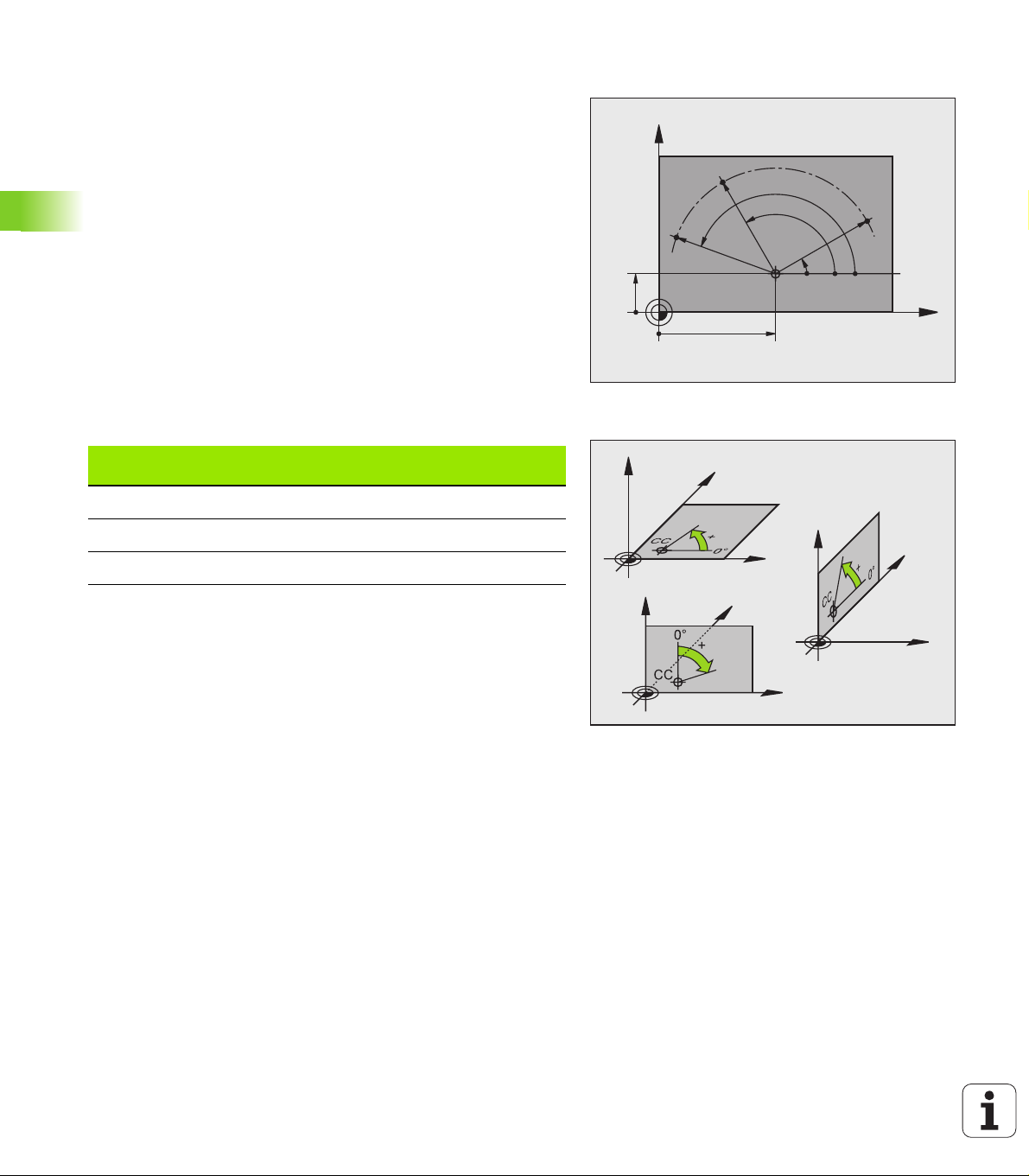
Polar coordinates
If the production drawing is dimensioned in Cartesian coordinates, you
also write the part program using Cartesian coordinates. For parts
containing circular arcs or angles it is often simpler to give the
dimensions in polar coordinates.
While the Cartesian coordinates X, Y and Z are three-dimensional and
can describe points in space, polar coordinates are two-dimensional
and describe points in a plane. Polar coordinates have their datum at a
circle center (CC), or pole. A position in a plane can be clearly defined
by the:
Polar Radius, the distance from the circle center CC to the position,
4.1 Fundamentals
and the
Polar Angle, the value of the angle between the reference axis and
the line that connects the circle center CC with the position.
Setting the pole and the angle reference axis
The pole is set by entering two Cartesian coordinates in one of the
three planes. These coordinates also set the reference axis for the
polar angle PA.
Y
PR
PA
2
PA
3
10
PR
CC
PA
PR
1
0°
X
30
Coordinates of the pole
(plane)
X/Y +X
Y/Z +Y
Z/X +Z
Reference axis for the angle
Z
Y
Z
Y
X
Z
Y
X
X
74 4 Programming: Fundamentals of NC, File Management, Programming Aids
Page 75

Absolute and incremental workpiece positions
Absolute workpiece positions
Absolute coordinates are position coordinates that are referenced to
the datum of the coordinate system (origin). Each position on the
workpiece is uniquely defined by its absolute coordinates.
Example 1: Holes dimensioned in absolute coordinates
Hole 1 Hole 2 Hole 3
X = 10 mm X = 30 mm X = 50 mm
Y = 10 mm Y = 20 mm Y = 30 mm
Y
3
30
2
20
1
10
4.1 Fundamentals
Incremental workpiece positions
Incremental coordinates are referenced to the last programmed
nominal position of the tool, which serves as the relative (imaginary)
datum. When you write a part program in incremental coordinates,
you thus program the tool to move by the distance between the
previous and the subsequent nominal positions. Incremental
coordinates are therefore also referred to as chain dimensions.
To program a position in incremental coordinates, enter the prefix “I”
before the axis.
Example 2: Holes dimensioned in incremental coordinates
Absolute coordinates of hole 4
X = 10 mm
Y = 10 mm
Hole 5, relative to 4 Hole 6, relative to 5
X = 20 mm X = 20 mm
Y = 10 mm Y = 10 mm
Absolute and incremental polar coordinates
Absolute polar coordinates always refer to the pole and the reference
axis.
Incremental polar coordinates always refer to the last programmed
nominal position of the tool.
X
10 20 30
Y
6
5
4
1 1
1
2
1
2
X
Y
+IPR
PR
PA
PR
0°
+IPA
PR
10
+IPA
CC
X
30
HEIDENHAIN TNC 320 75
Page 76

Setting the datum
A production drawing identifies a certain form element of the
workpiece, usually a corner, as the absolute datum. When setting the
datum, you first align the workpiece along the machine axes, and then
move the tool in each axis to a defined position relative to the
workpiece. Set the display of the TNC either to zero or to a known
position value for each position. This establishes the reference system
for the workpiece, which will be used for the TNC display and your part
program.
If the production drawing is dimensioned in relative coordinates,
simply use the coordinate transformation cycles (See “Coordinate
4.1 Fundamentals
Transformation Cycles” on page 334).
If the production drawing is not dimensioned for NC, set the datum at
a position or corner on the workpiece which is suitable for deducing
the dimensions of the remaining workpiece positions.
The fastest, easiest and most accurate way of setting the datum is by
using a 3-D touch probe from HEIDENHAIN. See “Setting the Datum
with a 3-D Touch Probe” in the Touch Probe Cycles User’s Manual.
Example
The workpiece drawing at right shows holes (1 to 4) whose
dimensions are shown with respect to an absolute datum with the
coordinates X=0, Y=0. Holes 5 to 7 are dimensioned with respect to a
relative datum with the absolute coordinates X=450, Y=750. With the
DATUM SHIFT cycle you can temporarily set the datum to the position
X=450, Y=750, to be able to program holes 5 to 7 without further
calculations.
750
320
Z
Y
MAX
X
MIN
Y
150
7
0
6
5
-150
0,1
±
300
3 4
0
21
325
450 900
950
76 4 Programming: Fundamentals of NC, File Management, Programming Aids
X
Page 77

4.2 File Management:
Fundamentals
Files
Files in the TNC Ty p e
Programs
In HEIDENHAIN format
In DIN/ISO format
.H
.I
Tables for
Tools
Tool changers
Datums
Presets
Touch probes
Backup files
Texts as
ASCII files
Log files
When you write a part program on the TNC, you must first enter a file
name. The TNC saves the program as a file with the same name. The
TNC can also save texts and tables as files.
The TNC provides a special file management window in which you can
easily find and manage your files. Here you can call, copy, rename and
erase files.
With the TNC you can manage and save files up to a total size of
300 MB.
Depending on the setting, the TNC generates a backup file
(*.bak) after editing and saving of NC programs. This can
reduce the memory space available to you.
.T
.TCH
.D
.PR
.TP
.BAK
.A
.TXT
4.2 File Management: Fundamentals
HEIDENHAIN TNC 320 77
Page 78

File names
When you store programs, tables and texts as files, the TNC adds an
extension to the file name, separated by a point. This extension
indicates the file type.
PROG20 .H
File name File type
File names should not exceed 25 characters, otherwise the TNC
cannot display the entire file name. The following characters are not
permitted in file names:
! “ ’ ( ) * + / ; < = > ? [ ] ^ ` { | } ~
The space (HEX 20) and delete (HEX 7F) characters are not
permitted in file names, either.
The maximum limit for the path and file name together is
256 characters (See “Paths” on page 80).
4.2 File Management: Fundamentals
78 4 Programming: Fundamentals of NC, File Management, Programming Aids
Page 79

Screen keypad
You can enter letters and special characters with the screen keypad or
(if available) with a PC keyboard connected over the USB port.
Enter the text with the screen keypad
Press the GOTO key if you want to enter a text, for example a
program name or directory name, using the screen keypad
The TNC opens a window in which the numeric entry field of the
TNC is displayed with the corresponding letters assigned
You can move the cursor to the desired character by repeatedly
pressing the respective key
Wait until the selected character is transferred to the entry field
before you enter the next character
Use the OK soft key to load the text into the open dialog field
Use the abc/ABC soft key to select upper or lower case. If your
machine tool builder has defined additional special characters, you can
call them with the SPECIAL CHARACTER soft key and insert them.
To delete individual characters, use the Backspace soft key.
Data backup
We recommend saving newly written programs and files on a PC at
regular intervals.
HEIDENHAIN provides a backup function for this purpose in the data
transfer software TNCremoNT. Your machine tool builder can provide
you with a copy of TNCBACK.EXE.
You additionally need a data medium on which all machine-specific
data, such as the PLC program, machine parameters, etc., are stored.
Please contact your machine tool builder for more information on both
the backup program and the floppy disk.
4.2 File Management: Fundamentals
Take the time occasionally to delete any unneeded files so
that the TNC always has enough memory space for
system files (such as the tool table) .
HEIDENHAIN TNC 320 79
Page 80

4.3 Working with the File Manager
Directories
If you save many programs in the TNC, we recommend that you save
your files in directories (folders) so that you can easily find your data.
You can divide a directory into further directories, which are called
subdirectories. With the –/+ key or ENT you can show or hide the
subdirectories.
Paths
A path indicates the drive and all directories and subdirectories under
which a file is saved. The individual names are separated by a
backslash “\”.
Example
The directory AUFTR1 was created on the TNC:\ drive. Then, in the
AUFTR1 directory, the directory NCPROG was created and the part
program PROG1.H was copied into it. The part program now has the
following path:
TNC:\AUFTR1\NCPROG\PROG1.H
4.3 Working with the File Manager
The chart at right illustrates an example of a directory display with
different paths.
TNC:\
AUFTR1
NCPROG
WZTAB
A35K941
ZYLM
TESTPROG
HUBER
KAR25T
80 4 Programming: Fundamentals of NC, File Management, Programming Aids
Page 81

Overview: Functions of the file manager
Function Soft key
Copying a file
Display a specific file type
Display the last 10 files that were selected
Delete a file or directory
Mark a file
Rename a file
Manage network drives
Select the editor
Protect a file against editing and erasure
Cancel file protection
Create new file
Sort files by properties
Copy a directory
Delete directory with all its subdirectories
Display all the directories of a particular drive
Rename directory
Create a new directory
4.3 Working with the File Manager
HEIDENHAIN TNC 320 81
Page 82

Calling the file manager
Press the PGM MGT key: the TNC displays the file
management window (Figure at right shows the
factory default setting. If the TNC displays a different
screen layout, press the WINDOW soft key.)
The narrow window on the left shows the available drives and
directories. Drives designate devices with which data are stored or
transferred. One drive is the internal memory of the TNC. Other drives
are the RS232, RS422, Ethernet and USB interfaces, which you can
used, for example, to connect a personal computer or other storage
device. A directory is always identified by a folder symbol to the left
and the directory name to the right. A subdirectory is displayed to the
right of and below its parent directory. A box with the + symbol in front
of the folder symbol indicates that there are further subdirectories,
which can be shown with the –/+ key or ENT.
The wide window on the right shows you all files that are stored in the
selected directory. Each file is shown with additional information,
illustrated in the table below.
Column Meaning
4.3 Working with the File Manager
FILE NAME Name with an extension, separated by a dot
(file type)
BYTE File size in bytes
STATUS
E
S
M
DATE Date on which file was last changed
TIME Time at which file was last changed
82 4 Programming: Fundamentals of NC, File Management, Programming Aids
File properties:
Program is selected in the Programming
mode of operation.
Program is selected in the Test Run mode of
operation.
Program is selected in a Program Run mode
of operation.
File is protected against editing and erasure.
Page 83

Selecting drives, directories and files
Call the file manager
With the arrow keys or the soft keys, you can move the highlight to
the desired position on the screen:
Moves the highlight from the left to the right window,
and vice versa.
Moves the highlight up and down within a window.
Moves the highlight one page up or down within a
window.
Step 1: Select drive
Move the highlight to the desired drive in the left window:
4.3 Working with the File Manager
Select a drive: Press the SELECT soft key or the ENT
or
Step 2: Select a directory
Move the highlight to the desired directory in the left-hand window—
the right-hand window automatically shows all files stored in the
highlighted directory.
key.
HEIDENHAIN TNC 320 83
Page 84

Step 3: Select a file
Press the SELECT TYPE soft key.
Press the soft key for the desired file type, or
Press the SHOW ALL soft key to display all files, or
Move the highlight to the desired file in the right window
The selected file is opened in the operating mode
from which you have called the File Manager: Press
or
Creating a new directory
4.3 Working with the File Manager
Move the highlight in the left window to the directory in which you
want to create a subdirectory.
the SELECT soft key or the ENT key.
NEW
DIRECTORY NAME?
84 4 Programming: Fundamentals of NC, File Management, Programming Aids
Enter the new file name, and confirm with ENT.
Press the OK soft key to confirm, or
abort with the CANCEL soft key.
Page 85

Copying a single file
Move the highlight to the file you wish to copy.
Press the COPY soft key to select the copy function.
The TNC opens a pop-up window
Enter the name of the destination file and confirm your
entry with the ENT key or OK soft key: The TNC
copies the file to the active directory or to the
corresponding destination directory. The original file
is retained.
Copying a directory
Move the highlight in the left window onto the directory you want to
copy. Then press the COPY DIR soft key instead of the COPY soft key.
Subdirectories can be copied by the TNC at the same time.
Making a setting in a selection box
In various dialogs, the TNC opens a pop-up window in which you can
make settings in selection boxes.
Move the cursor into the desired selection box and press the GOTO
key
Use the arrow keys to position the cursor to the required setting
With the OK soft key you confirm the value, and with the CANCEL
soft key you discard the selection
4.3 Working with the File Manager
HEIDENHAIN TNC 320 85
Page 86

Choosing one of the last 10 files selected
Call the file manager
Display the last 10 files selected: Press the LAST
FILES soft key.
Use the arrow keys to move the highlight to the file you wish to select:
Moves the highlight up and down within a window.
Select a file: Press the OK soft key or ENT
or
4.3 Working with the File Manager
Deleting a file
Move the highlight to the file you want to delete
To select the erasing function, press the DELETE soft
key.
To confirm, press the OK soft key or
To cancel deletion, press the CANCEL soft key
Deleting a directory
Delete all files and subdirectories stored in the directory that you
want to delete
Move the highlight to the directory you want to delete.
To select the erasing function, press the DELETE ALL
soft key. The TNC asks whether you really want to
erase the subdirectories and files.
To confirm, press the OK soft key or
To cancel deletion, press the CANCEL soft key
86 4 Programming: Fundamentals of NC, File Management, Programming Aids
Page 87

Marking files
Tagging functions Soft key
Tag a single file
Tag all files in the directory
Untag a single file
Untag all files
Some functions, such as copying or erasing files, can not only be used
for individual files, but also for several files at once. To tag several files,
proceed as follows:
Move the highlight to the first file.
To display the tagging functions, press the TAG soft
key.
Tag a file by pressing the TAG FILE soft key.
Move the highlight to the next file you wish to mark:
To tag more files, press the TAG FILE soft key.
To copy the marked files, with the back soft key,
leave the TAG function
To copy the marked files, select the COPY soft key
To delete the marked files, press the back soft key to
exit the marking function and then press the DELETE
soft key
4.3 Working with the File Manager
HEIDENHAIN TNC 320 87
Page 88

Renaming a file
Move the highlight to the file you wish to rename.
Select the renaming function.
Enter the new file name; the file type cannot be
changed.
To rename: Press the OK soft key or the ENT key
File sorting
Select the folder in which you wish to sort the files
Select the SORT soft-key
Select the soft key with the corresponding display
criterion
Additional functions
Protecting a file / Canceling file protection
Move the highlight to the file you want to protect.
To select the additional functions, press the MORE
4.3 Working with the File Manager
FUNCTIONS soft key.
To enable file protection, press the PROTECT soft
key. The file is distinguished by a symbol.
To cancel file protection, proceed in the same way
using the UNPROTECT soft key.
Select the editor
Move the highlight in the right window onto the file you want to
open.
To select the additional functions, press the MORE
FUNCTIONS soft key.
To select the editor with which to open the selected
file, press the SELECT EDITOR soft key.
Mark the desired editor.
Press the OK soft key to open the file.
Activate or deactivate USB devices.
To select the additional functions, press the MORE
FUNCTIONS soft key.
Shift the soft-key row.
Select the soft key for activating or deactivating.
88 4 Programming: Fundamentals of NC, File Management, Programming Aids
Page 89

Data transfer to or from an external data medium
You might have to set up the data interface before you
can transfer data to an external data medium (See
“Setting the Data Interfaces” on page 475).
Depending on the data transfer software you use,
problems can occur occasionally when you transmit data
over a serial interface. They can be overcome by repeating
the transmission.
Call the file manager
Select the screen layout for data transfer: press the
WINDOW soft key. Select the desired directory in
both halves of the screen. In the left half of the screen
the TNC shows, for example, all files saved on its hard
disk. In the right half of the screen it shows all files
saved on the external data medium. Use the SHOW
FILES and SHOW TREE soft keys to switch between
the folder view and file view.
4.3 Working with the File Manager
Use the arrow keys to highlight the file(s) that you want to transfer:
Moves the highlight up and down within a window.
Moves the highlight from the left to the right window,
and vice versa.
If you wish to copy from the TNC to the external data medium, move
the highlight in the left window to the file to be transferred.
HEIDENHAIN TNC 320 89
Page 90

To transfer a single file, position the highlight on the desired file, or
To transfer several files: Press the TAG soft key (in
the second soft-key row, See “Marking files,” page
87) and mark the corresponding files. With the back
soft key, exit the TAG function again.
Press the COPY soft key
Confirm with the OK soft key or with the ENT key. For long programs,
a status window appears on the TNC informing you of the copying
progress.
To end data transfer, move the highlight into the left
window and then press the WINDOW soft key. The
standard file manager window is displayed again.
4.3 Working with the File Manager
To select another directory in the split-screen display,
press the SHOW TREE soft key. If you press the SHOW
FILES soft key, the TNC shows the content of the
selected directory!
90 4 Programming: Fundamentals of NC, File Management, Programming Aids
Page 91

Copying files into another directory
Select a screen layout with two equally sized windows.
To display directories in both windows, press the SHOW TREE soft
key.
In the right window
Move the highlight to the directory to copy the files to and display
the files in this directory with the SHOW FILES soft key.
In the left window
Select the directory with the files to copy and press the SHOW
FILES soft key to display them.
Call the file tagging functions.
Move the highlight to the files to be copied and mark
them. You can tag several files in this way, if desired.
Copy the tagged files into the target directory.
Additional marking functions: See “Marking files,” page 87.
If you have tagged files in both the left and right windows, the TNC
copies from the directory in which the highlight is located.
Overwriting files
If you copy files into a directory in which other files are stored under
the same name, the TNC will reply with a “protected file” error
message. Use the TAG function to overwrite the file anyway:
To overwrite two or more files, mark them in the "existing files" pop-
up window and press the OK soft key
To leave the files as they are, press the CANCEL soft key
4.3 Working with the File Manager
HEIDENHAIN TNC 320 91
Page 92

The TNC in a network
To connect the Ethernet card to your network, See
“Ethernet Interface,” page 480.
The TNC logs error messages during network operation
(See “Ethernet Interface” on page 480).
If the TNC is connected to a network, it also displays the connected
network drives in the directory window (left half of the screen). All the
functions described above (selecting a drive, copying files, etc.) also
apply to network drives, provided that you have been granted the
corresponding rights.
Connecting and disconnecting a network drive
To select the program management: Press the PGM
MGT key. If necessary, press the WINDOW soft key
to set up the screen as it is shown at the upper right.
To manage the network drives: Press the NETWORK
soft key (second soft-key row). In the right-hand
window the TNC shows the network drives available
for access. With the soft keys described below you
can define the connection for each drive.
4.3 Working with the File Manager
Function Soft key
Establish the network connection. If the
connection is active, the TNC marks the Mnt
column.
Delete network connection.
Automatically establish network connection
whenever the TNC is switched on. The TNC
marks the Auto column if the connection is
established automatically
Use the PING function to test your network
connection
If you press the NETWORK INFO soft key, the
TNC displays the current network settings
92 4 Programming: Fundamentals of NC, File Management, Programming Aids
Page 93

USB devices on the TNC
Backing up data from or loading onto the TNC is especially easy with
USB devices. The TNC supports the following USB block devices:
Floppy disk drives with FAT/VFAT file system
Memory sticks with the FAT/VFAT file system
Hard disks with the FAT/VFAT file system
CD-ROM drives with the Joliet (ISO 9660) file system
The TNC automatically detects these types of USB devices when
connected. The TNC does not support USB devices with other file
systems (such as NTFS). After connection, the TNC displays an error
message.
The TNC also displays an error message if you connect a
USB hub. In this case simply acknowledge the message
with the CE key.
In theory, you should be able to connect all USB devices
with the file systems mentioned above to the TNC. If
problems occur nevertheless, please contact
HEIDENHAIN.
The USB devices appear as separate drives in the directory tree, so
you can use the file-management functions described in the earlier
chapters correspondingly.
In order to remove a USB device, you must proceed as follows:
Press the PGM MGT soft key to call the file manager.
Select the left window with the arrow key.
Use the arrow keys to select the USB device to be
removed.
Scroll through the soft-key row.
Select additional functions.
Select the function for removing USB devices: The
TNC removes the USB device from the directory tree
Exit the file manager.
In order to re-establish a connection with a USB device that has been
removed, press the following soft key:
Select the function for reconnection of USB devices.
4.3 Working with the File Manager
HEIDENHAIN TNC 320 93
Page 94

4.4 Creating and Writing Programs
Organization of an NC program in HEIDENHAIN conversational format
A part program consists of a series of program blocks. The figure at
right illustrates the elements of a block.
The TNC numbers the blocks in ascending sequence.
The first block of a program is identified by BEGIN PGM, the program
name and the active unit of measure.
The subsequent blocks contain information on:
The workpiece blank
Tool definitions, tool calls
Approaching a safe position
Feed rates and spindle speeds, as well as
Path contours, cycles and other functions
The last block of a program is identified by END PGM, the program name
and the active unit of measure.
Block
10 L X+10 Y+5 R0 F100 M3
Path function
Block number
Words
4.4 Creating and Writing Programs
After each tool call, HEIDENHAIN recommends always
traversing to a safe position, from which the TNC can
position the tool for machining without causing a collision!
Define the blank: BLK FORM
After initiating a new program, you define a cuboid workpiece blank.
To define the workpiece blank, press the SPEC FCT soft key and then
the BLK FORM soft key. This definition is needed for the TNC’s
graphic simulation feature. The sides of the workpiece blank lie parallel
to the X, Y and Z axes and can be up to 100 000 mm long. The blank
form is defined by two of its corner points:
MIN point: the smallest X, Y and Z coordinates of the blank form,
entered as absolute values.
MAX point: the largest X, Y and Z coordinates of the blank form,
entered as absolute or incremental values.
You only need to define the blank form if you wish to run
a graphic test for the program!
94 4 Programming: Fundamentals of NC, File Management, Programming Aids
Page 95

Creating a new part program
0
0
0
You always enter a part program in the Programming mode of
operation. An example of program initiation:
Select the Programming mode of operation.
Press the PGM MGT key to call the file manager.
Select the directory in which you wish to store the new program:
FILE NAME = 123.H
Enter the new program name and confirm your entry
with the ENT key.
To select the unit of measure, press the MM or INCH
soft key. The TNC switches the screen layout and
initiates the dialog for defining the BLK FORM.
WORKING SPINDLE AXIS X/Y/Z?
4.4 Creating and Writing Programs
Enter the spindle axis.
DEF BLK FORM: MIN CORNER?
Enter in sequence the X, Y and Z coordinates of the
MIN point.
-40
DEF BLK FORM: MAX CORNER?
100
100
HEIDENHAIN TNC 320 95
Enter in sequence the X, Y and Z coordinates of the
MAX point.
Page 96

Example: Display the BLK form in the NC program
0 BEGIN PGM NEW MM
1 BLK FORM 0.1 Z X+0 Y+0 Z-40
2 BLK FORM 0.2 X+100 Y+100 Z+0
3 END PGM NEW MM
The TNC automatically generates the block numbers as well as the
BEGIN and END blocks.
If you do not wish to define a blank form, cancel the dialog
at Working spindle axis X/Y/Z by pressing the DEL key!
The TNC can display the graphics only if the shortest side
is at least 50 µm long and the longest side is no longer
than 99 999.999 mm.
4.4 Creating and Writing Programs
Program begin, name, unit of measure
Spindle axis, MIN point coordinates
MAX point coordinates
Program end, name, unit of measure
96 4 Programming: Fundamentals of NC, File Management, Programming Aids
Page 97
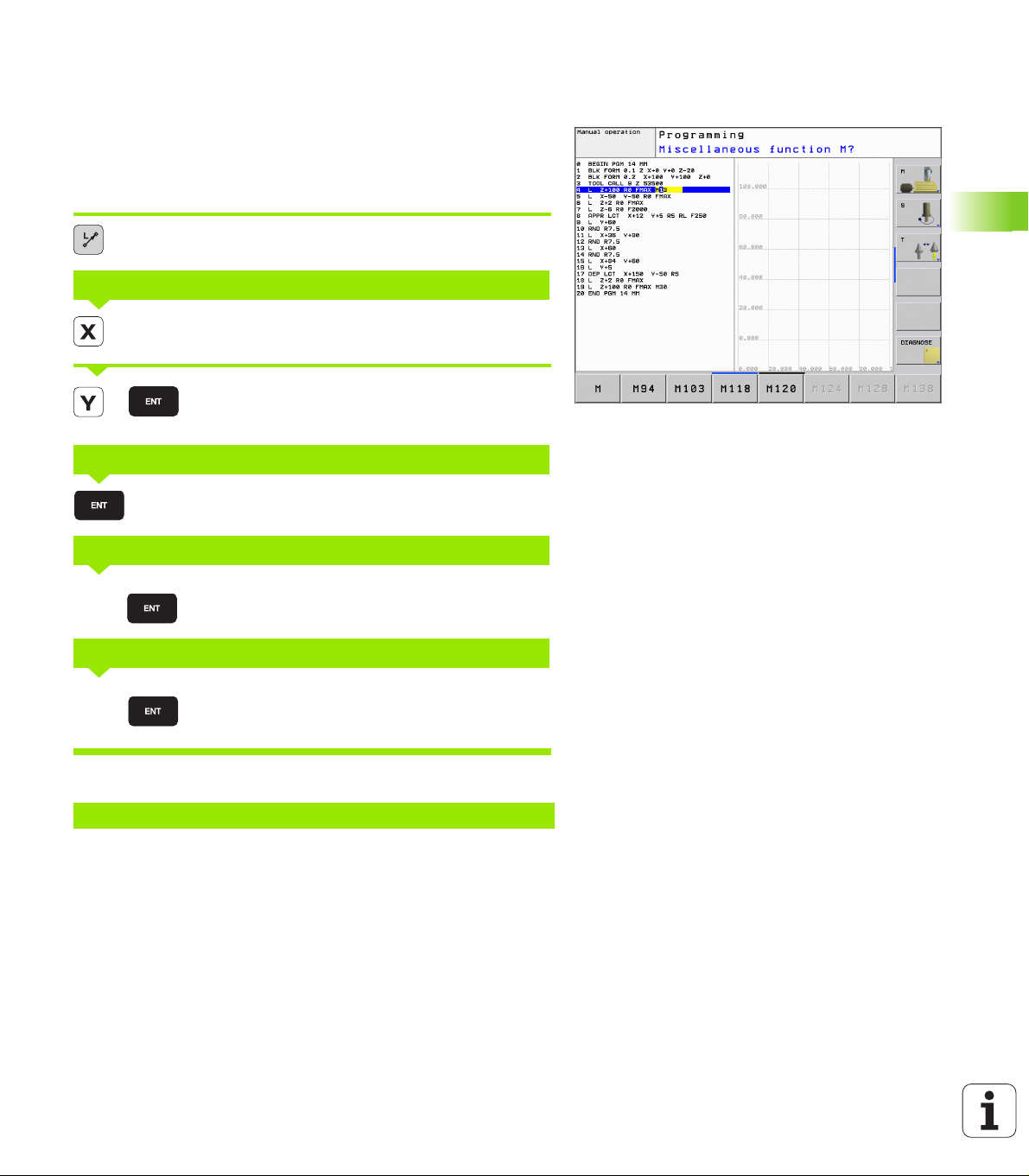
Programming tool movements in conversational
20
format
To program a block, initiate the dialog by pressing a function key. In the
screen headline, the TNC then asks you for all the information
necessary to program the desired function.
Example of a dialog
Dialog initiation
COORDINATES?
10
RADIUS COMP. RL/RR/NO COMP. ?
FEED RATE F=? / F MAX = ENT
00
MISCELLANEOUS FUNCTION M?
The program-block window displays the following line:
3 L X+10 Y+5 R0 F100 M3
Enter the target coordinate for the X axis.
Enter the target coordinate for the Y axis, and go to
the next question with ENT
Enter “No radius compensation” and go to the next
question with ENT.
Enter a feed rate of 100 mm/min for this path contour;
go to the next question with ENT.
Enter the miscellaneous function M3 “spindle ON.”
Pressing the ENT key terminates this dialog.
4.4 Creating and Writing Programs
HEIDENHAIN TNC 320 97
Page 98

Possible feed rate input
Functions for setting the feed rate Soft key
Rapid traverse
Traverse feed rate automatically calculated in
TOOL CALL
Move at the programmed feed rate (unit of
measure is mm/min)
Functions for conversational guidance Key
Ignore the dialog question
End the dialog immediately
Abort the dialog and erase the block
Actual position capture
4.4 Creating and Writing Programs
The TNC enables you to transfer the current tool position into the
program, for example during
Positioning-block programming
Cycle programming, and
Tool definition with TOOL DEF.
To transfer the correct position values, proceed as follows:
Place the input box at the position in the block where you want to
insert a position value.
Select the actual-position-capture function: In the soft-
key row the TNC displays the axes whose positions
can be transferred.
Select the axis: The TNC writes the current position of
the selected axis into the active input box.
In the working plane the TNC always captures the
coordinates of the tool center, even though tool radius
compensation is active.
In the tool axis the TNC always captures the coordinates
of the tool tip and thus always takes the active tool length
compensation into account.
The actual-position-capture function is not allowed if the
tilted working plane function is active.
98 4 Programming: Fundamentals of NC, File Management, Programming Aids
Page 99

Editing a program
You cannot save a program while it is being run by the TNC
in a machine operating mode. The TNC allows you to edit
the program, but it does not save the changes and
responds instead with an error message. If you wish, you
can save changes under another file name.
While you are creating or editing a part program, you can select any
desired line in the program or individual words in a block with the
arrow keys or the soft keys:
Function Soft key/key
Go to previous page
Go to next page
Go to beginning of program
Go to end of program
Change the position of the current block on
the screen: Press this soft key to display
additional program blocks that are
programmed before the current block.
4.4 Creating and Writing Programs
Change the position of the current block on
the screen: Press this soft key to display
additional program blocks that are
programmed after the current block.
Move from one block to the next
Select individual words in a block
To select a certain block, press the GOTO key,
enter the desired block number, and confirm
with the ENT key.
HEIDENHAIN TNC 320 99
Page 100

Function Soft key/key
Set the selected word to zero
Erase an incorrect number
Clear a (non-blinking) error message
Delete the selected word
Delete the selected block
Erase cycles and program sections
Deleting individual characters
Insert the block that was last edited or
deleted.
4.4 Creating and Writing Programs
Inserting blocks at any desired location
Select the block after which you want to insert a new block and
initiate the dialog.
Editing and inserting words
Select a word in a block and overwrite it with the new one. The plain-
language dialog is available while the word is highlighted.
To accept the change, press the END key.
If you want to insert a word, press the horizontal arrow key repeatedly
until the desired dialog appears. You can then enter the desired value.
100 4 Programming: Fundamentals of NC, File Management, Programming Aids
 Loading...