

Page 1
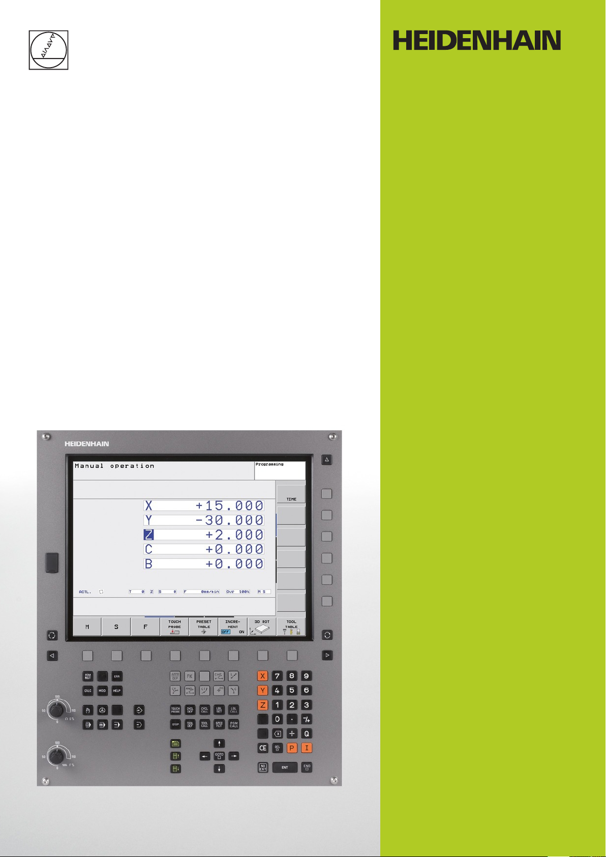
TNC 320
User’s Manual
DIN/ISO Programming
NC Software
340551-06
340554-06
English (en)
5/2013
Page 2
Controls of the TNC
Controls of the TNC
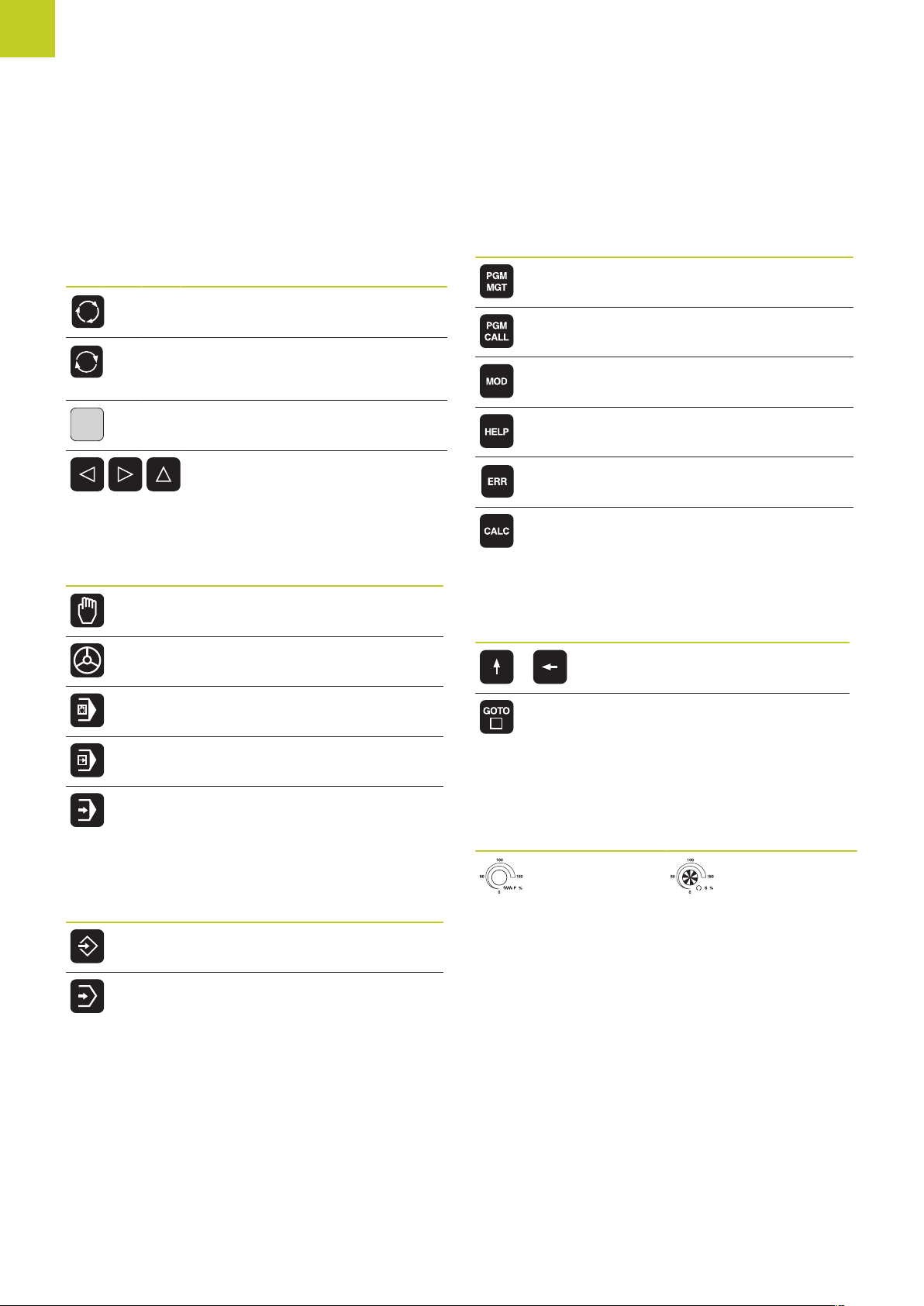
Keys on visual display unit
Key Function
Select split screen layout
Toggle the display between
machining and programming
modes
Soft keys for selecting functions on
screen
Shifting between soft-key rows
Machine operating modes
Key Function
Manual operation
Electronic handwheel
Program/file management, TNC functions
Key Function
Select or delete programs and files,
external data transfer
Define program call, select datum
and point tables
Select MOD functions
Display help text for NC error
messages, call TNCguide
Display all current error messages
Show calculator
Navigation keys
Key Function
Move highlight
Positioning with manual data input
Program run, single block
Program run, full sequence
Programming modes
Key Function
Programming
Test run
Go directly to blocks, cycles and
parameter functions
Potentiometer for feed rate and spindle speed
Feed rate Spindle speed
2
TNC 320 | User's Manual for DIN/ISO Programming | 5/2013
Page 3
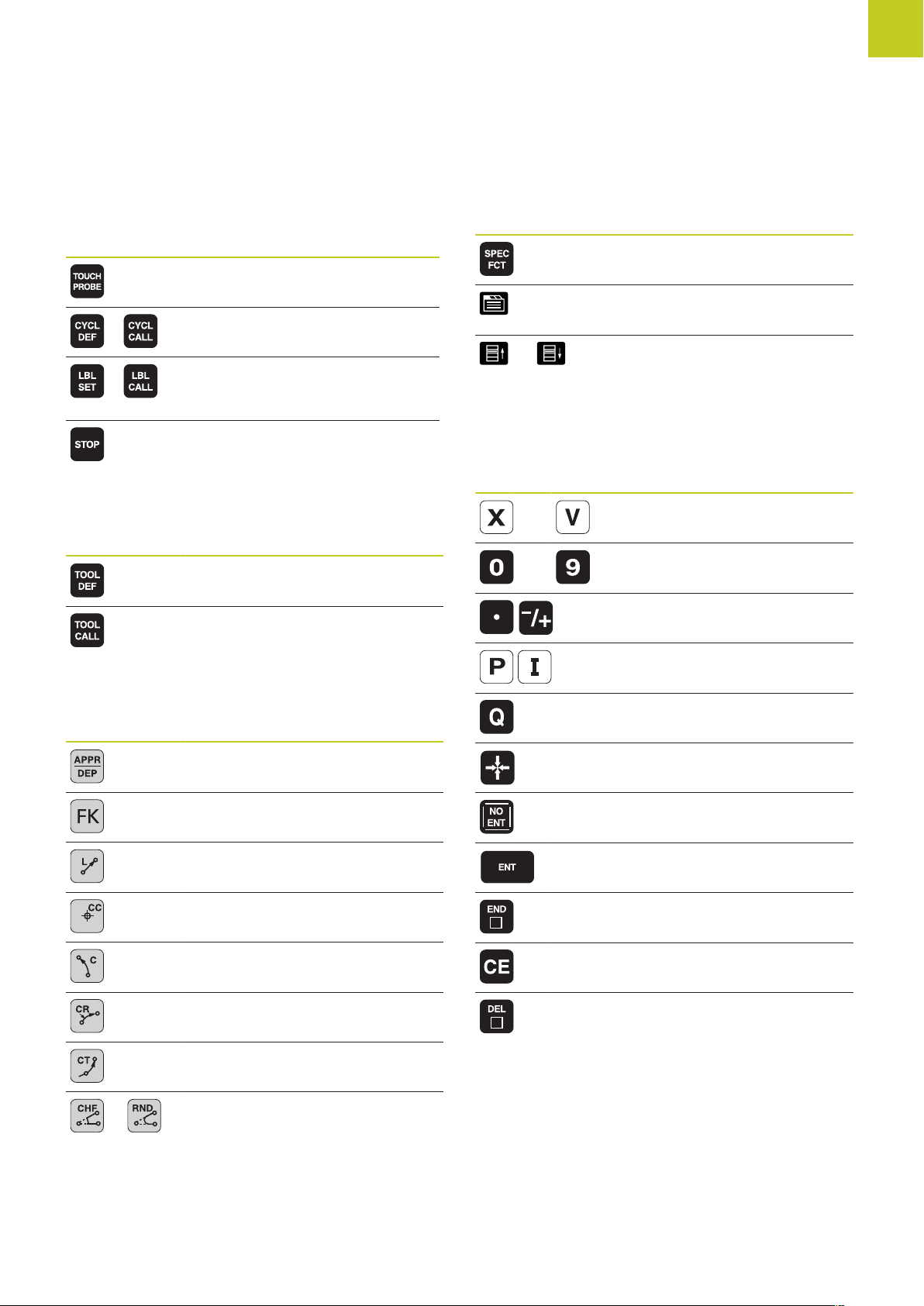
Cycles, subprograms and program section repeats
Key Function
Define touch probe cycles
Define and call cycles
Enter and call labels for
subprogramming and program
section repeats
Enter program stop in a program
Tool functions
Key Function
Define tool data in the program
Call tool data
Special functions
Key Function
Show special functions
Select the next tab in forms
Up/down one dialog box or button
Entering and editing coordinate axes and numbers
Key Function
Select coordinate axes or enter
. . . .
. . . .
them in a program
Numbers
Decimal point / Reverse algebraic
sign
Programming path movements
Key Function
Approach/depart contour
FK free contour programming
Straight line
Circle center/pole for polar
coordinates
Circular arc with center
Circle with radius
Circular arc with tangential
connection
Chamfer/Corner rounding
Polar coordinate input /
Incremental values
Q-parameter programming / Q
parameter status
Save actual position or values from
calculator
Skip dialog questions, delete
words
Confirm entry and resume dialog
Conclude block and exit entry
Clear numerical entry or TNC error
message
Abort dialog, delete program
section
TNC 320 | User's Manual for DIN/ISO Programming | 5/2013
3
Page 4

Controls of the TNC
4
TNC 320 | User's Manual for DIN/ISO Programming | 5/2013
Page 5

Fundamentals
Page 6

Fundamentals
About this manual
About this manual
The symbols used in this manual are described below.
This symbol indicates that important notes about the
function described must be regarded.
This symbol indicates that there is one or more
of the following risks when using the described
function:
Danger to workpiece
Danger to fixtures
Danger to tool
Danger to machine
Danger to operator
This symbol indicates a possibly dangerous situation
that may cause light injuries if not avoided.
This symbol indicates that the described function
must be adapted by the machine tool builder. The
function described may therefore vary depending on
the machine.
This symbol indicates that you can find detailed
information about a function in another manual.
Would you like any changes, or have you found any errors?
We are continuously striving to improve our documentation for you.
Please help us by sending your requests to the following e-mail
address: tnc-userdoc@heidenhain.de.
6
TNC 320 | User's Manual for DIN/ISO Programming | 5/2013
Page 7

TNC model, software and features
TNC model, software and features
This manual describes functions and features provided by TNCs as
of the following NC software numbers.
TNC model NC software number
TNC 320 340551-06
TNC 320 Programming Station 340554-06
The suffix E indicates the export version of the TNC. The export
version of the TNC has the following limitations:
Simultaneous linear movement in up to 4 axes
The machine tool builder adapts the usable features of the TNC to
his machine by setting machine parameters. Some of the functions
described in this manual may therefore not be among the features
provided by the TNC on your machine tool.
TNC functions that may not be available on your machine include:
Tool measurement with the TT
Please contact your machine tool builder to become familiar with
the features of your machine.
Many machine manufacturers, as well as HEIDENHAIN, offer
programming courses for the TNCs. We recommend these courses
as an effective way of improving your programming skill and
sharing information and ideas with other TNC users.
User's Manual for Cycle Programming:
All of the cycle functions (touch probe cycles and
fixed cycles) are described in the Cycle Programming
User’s Manual. Please contact HEIDENHAIN if you
require a copy of this User’s Manual. ID: 679 220-xx
TNC 320 | User's Manual for DIN/ISO Programming | 5/2013
7
Page 8

Fundamentals
TNC model, software and features
Software options
The TNC 320 features various software options that can be enabled by your machine tool builder. Each option is to
be enabled separately and contains the following respective functions:
Hardware, options
■
1st additional axis for 4 axes plus spindle
■
2nd additional axis for 5 axes plus spindle
Software option 1 (option number 08)
Rotary table machining
Coordinate transformation
Interpolation
HEIDENHAIN DNC (option number 18)
Software option for additional conversational languages (option number 41)
Additional conversational
languages
■
Programming of cylindrical contours as if in two axes
■
Feed rate in distance per minute
■
Working plane, tilting the ...
■
Circle in 3 axes with tilted working plane (spacial arc)
Communication with external PC applications over COM component
■
Slovenian
■
Norwegian
■
Slovak
■
Latvian
■
Korean
■
Estonian
■
Turkish
■
Romanian
■
Lithuanian
■
8
TNC 320 | User's Manual for DIN/ISO Programming | 5/2013
Page 9

TNC model, software and features
Feature Content Level (upgrade functions)
Along with software options, significant further improvements
of the TNC software are managed via the Feature Content Level
upgrade functions. Functions subject to the FCL are not available
simply by updating the software on your TNC.
All upgrade functions are available to you without
surcharge when you receive a new machine.
Upgrade functions are identified in the manual with FCL n, where n
indicates the sequential number of the feature content level.
You can purchase a code number in order to permanently enable
the FCL functions. For more information, contact your machine tool
builder or HEIDENHAIN.
Intended place of operation
The TNC complies with the limits for a Class A device in
accordance with the specifications in EN 55022, and is intended for
use primarily in industrially-zoned areas.
Legal information
This product uses open source software. Further information is
available on the control under
Programming and Editing operating mode
MOD function
LICENSE INFO soft key
TNC 320 | User's Manual for DIN/ISO Programming | 5/2013
9
Page 10

Fundamentals
TNC model, software and features
New functions
New functions 34055x-06
The active tool-axis direction can now be activated in manual
mode and during handwheel superimposition as a virtual tool axis
(Superimposing handwheel positioning during program run: M118 ,
page 286).
Writing and reading data in freely definable tables (Freely definable
tables, page 302).
New touch probe cycle 484 for calibrating the wireless TT 449 tool
touch probe (see User's Manual for Cycles).
The new HR 520 and HR 550 FS handwheels are supported
(Traverse with electronic handwheels, page 342).
New machining cycle 225 ENGRAVING (see User’s Manual for
Cycle Programming)
New manual probing cycle "Center line as datum" (Setting a center
line as datum , page 381).
New function for rounding corners (Rounding corners: M197,
page 292).
External access to the TNC can now be blocked with a MOD
function (External access).
10
TNC 320 | User's Manual for DIN/ISO Programming | 5/2013
Page 11

TNC model, software and features
Modified functions 34055x-06
The maximum number of characters for the NAME and DOC fields
in the tool table has been increased from 16 to 32 (Enter tool data
into the table, page 142).
Operation and position behavior of the manual probing cycles has
been improved (Using 3-D touch probes , page 361).
Predefined values can now be entered into a cycle parameter
with the PREDEF function in cycles (see User’s Manual for Cycle
Programming).
A new optimization algorithm is now used with the KinematicsOpt
cycles (see User’s Manual for Cycle Programming).
With Cycle 257, circular stud milling, a parameter is now available
with which you can determine the approach position on the stud
(see User's Manual for Cycle Programming)
With Cycle 256, rectangular stud, a parameter is now available with
which you can determine the approach position on the stud (see
User's Manual for Cycle Programming).
With the "Basic Rotation" probing cycle, workpiece misalignment
can now be compensated for via a table rotation (Compensation of
workpiece misalignment by rotating the table, page 374)
TNC 320 | User's Manual for DIN/ISO Programming | 5/2013
11
Page 12

Fundamentals
TNC model, software and features
12
TNC 320 | User's Manual for DIN/ISO Programming | 5/2013
Page 13

Contents
1 First Steps with the TNC 320......................................................................................................... 39
2 Introduction.......................................................................................................................................61
3 Programming: Fundamentals, file management...........................................................................77
4 Programming: Programming aids................................................................................................ 113
5 Programming: Tools....................................................................................................................... 137
6 Programming: Programming contours........................................................................................ 165
7 Programming: Subprograms and program section repeats...................................................... 193
8 Programming: Q Parameters.........................................................................................................209
9 Programming: Miscellaneous functions.......................................................................................273
10 Programming: Special functions.................................................................................................. 293
11 Programming: Multiple Axis Machining...................................................................................... 309
12 Manual operation and setup.........................................................................................................337
13 Positioning with Manual Data Input............................................................................................393
14 Test run and program run............................................................................................................. 399
15 MOD functions................................................................................................................................425
16 Tables and overviews.....................................................................................................................449
TNC 320 | User's Manual for DIN/ISO Programming | 5/2013
13
Page 14

Contents
14
TNC 320 | User's Manual for DIN/ISO Programming | 5/2013
Page 15

1 First Steps with the TNC 320......................................................................................................... 39
1.1 Overview................................................................................................................................................. 40
1.2 Machine switch-on.................................................................................................................................40
Acknowledging the power interruption and moving to the reference points........................................... 40
1.3 Programming the first part...................................................................................................................41
Selecting the correct operating mode..................................................................................................... 41
The most important TNC keys.................................................................................................................41
Creating a new program/file management.............................................................................................. 42
Defining a workpiece blank......................................................................................................................43
Program layout......................................................................................................................................... 44
Programming a simple contour................................................................................................................45
Creating a cycle program.........................................................................................................................48
1.4 Graphically testing the first part..........................................................................................................50
Selecting the correct operating mode..................................................................................................... 50
Selecting the tool table for the test run..................................................................................................50
Choosing the program you want to test................................................................................................. 51
Selecting the screen layout and the view............................................................................................... 51
Starting the test run.................................................................................................................................52
1.5 Setting up tools..................................................................................................................................... 53
Selecting the correct operating mode..................................................................................................... 53
Preparing and measuring tools................................................................................................................ 53
The tool table TOOL.T............................................................................................................................. 54
The pocket table TOOL_P.TCH.................................................................................................................55
1.6 Workpiece setup.....................................................................................................................................56
Selecting the correct operating mode..................................................................................................... 56
Clamping the workpiece.......................................................................................................................... 56
Workpiece alignment with 3-D touch probe............................................................................................57
Datum setting with 3-D touch probe.......................................................................................................58
1.7 Running the first program.................................................................................................................... 59
Selecting the correct operating mode..................................................................................................... 59
Choosing the program you want to run.................................................................................................. 59
Start the program.....................................................................................................................................59
TNC 320 | User's Manual for DIN/ISO Programming | 5/2013
15
Page 16

Contents
2 Introduction.......................................................................................................................................61
2.1 The TNC 320........................................................................................................................................... 62
Programming: HEIDENHAIN conversational and ISO formats.................................................................62
Compatibility.............................................................................................................................................62
2.2 Visual display unit and operating panel..............................................................................................63
Display screen..........................................................................................................................................63
Setting the screen layout.........................................................................................................................64
Control Panel............................................................................................................................................64
2.3 Modes of Operation...............................................................................................................................65
Manual Operation and El. Handwheel..................................................................................................... 65
Positioning with Manual Data Input.........................................................................................................65
Programming............................................................................................................................................ 65
Test Run................................................................................................................................................... 66
Program Run, Full Sequence and Program Run, Single Block.................................................................66
2.4 Status displays....................................................................................................................................... 67
"General" status display............................................................................................................................67
Additional status displays.........................................................................................................................68
2.5 Accessories: HEIDENHAIN 3-D Touch Probes and Electronic Handwheels.......................................74
3-D touch probes..................................................................................................................................... 74
HR electronic handwheels.......................................................................................................................75
16
TNC 320 | User's Manual for DIN/ISO Programming | 5/2013
Page 17

3 Programming: Fundamentals, file management...........................................................................77
3.1 Fundamentals......................................................................................................................................... 78
Position encoders and reference marks.................................................................................................. 78
Reference system.................................................................................................................................... 78
Reference system on milling machines...................................................................................................79
Designation of the axes on milling machines..........................................................................................79
Polar coordinates...................................................................................................................................... 80
Absolute and incremental workpiece positions.......................................................................................81
Selecting the datum.................................................................................................................................82
3.2 Opening programs and entering..........................................................................................................83
Organization of an NC program in DIN/ISO format................................................................................. 83
Define the blank: G30/G31...................................................................................................................... 83
Opening a new part program.................................................................................................................. 84
Programming tool movements in DIN/ISO.............................................................................................. 85
Actual position capture.............................................................................................................................86
Editing a program.....................................................................................................................................87
The TNC search function......................................................................................................................... 90
3.3 File manager: Fundamentals.................................................................................................................92
Files.......................................................................................................................................................... 92
Data Backup............................................................................................................................................. 94
TNC 320 | User's Manual for DIN/ISO Programming | 5/2013
17
Page 18

Contents
3.4 Working with the file manager............................................................................................................ 95
Directories................................................................................................................................................ 95
Paths.........................................................................................................................................................95
Overview: Functions of the file manager................................................................................................ 96
Calling the file manager........................................................................................................................... 97
Selecting drives, directories and files...................................................................................................... 98
Creating a new directory......................................................................................................................... 99
Creating a new file...................................................................................................................................99
Copying a single file.................................................................................................................................99
Copying files into another directory.......................................................................................................100
Copying a table...................................................................................................................................... 101
Copying a directory................................................................................................................................ 102
Choosing one of the last files selected.................................................................................................102
Deleting a file.........................................................................................................................................103
Deleting a directory................................................................................................................................103
Tagging files........................................................................................................................................... 104
Renaming a file...................................................................................................................................... 105
Sorting files............................................................................................................................................ 105
Additional functions................................................................................................................................106
Data transfer to/from an external data medium.................................................................................... 107
The TNC in a network............................................................................................................................109
USB devices on the TNC.......................................................................................................................110
18
TNC 320 | User's Manual for DIN/ISO Programming | 5/2013
Page 19

4 Programming: Programming aids................................................................................................ 113
4.1 Screen keyboard...................................................................................................................................114
Enter the text with the screen keyboard...............................................................................................114
4.2 Adding comments................................................................................................................................115
Application.............................................................................................................................................. 115
Entering comments during programming..............................................................................................115
Inserting comments after program entry.............................................................................................. 115
Entering a comment in a separate block...............................................................................................115
Functions for editing of the comment................................................................................................... 116
4.3 Structuring programs...........................................................................................................................117
Definition and applications.....................................................................................................................117
Displaying the program structure window / Changing the active window.............................................117
Inserting a structuring block in the (left) program window....................................................................117
Selecting blocks in the program structure window............................................................................... 117
4.4 Calculator.............................................................................................................................................. 118
Operation................................................................................................................................................118
4.5 Programming graphics........................................................................................................................ 120
Generating / not generating graphics during programming................................................................... 120
Generating a graphic for an existing program....................................................................................... 120
Block number display ON/OFF...............................................................................................................121
Erasing the graphic................................................................................................................................ 121
Showing grid lines..................................................................................................................................121
Magnification or reduction of details..................................................................................................... 122
TNC 320 | User's Manual for DIN/ISO Programming | 5/2013
19
Page 20

Contents
4.6 Error messages..................................................................................................................................... 123
Display of errors.....................................................................................................................................123
Open the error window......................................................................................................................... 123
Closing the error window...................................................................................................................... 123
Detailed error messages........................................................................................................................124
INTERNAL INFO soft key.......................................................................................................................124
Clearing errors........................................................................................................................................125
Error log..................................................................................................................................................125
Keystroke log..........................................................................................................................................126
Informational texts................................................................................................................................. 127
Saving service files................................................................................................................................ 127
Calling the TNCguide help system........................................................................................................ 128
4.7 TNCguide context-sensitive help system..........................................................................................129
Application.............................................................................................................................................. 129
Working with the TNCguide.................................................................................................................. 130
Downloading current help files.............................................................................................................. 134
20
TNC 320 | User's Manual for DIN/ISO Programming | 5/2013
Page 21

5 Programming: Tools....................................................................................................................... 137
5.1 Entering tool-related data................................................................................................................... 138
Feed rate F.............................................................................................................................................138
Spindle speed S..................................................................................................................................... 139
5.2 Tool data................................................................................................................................................140
Requirements for tool compensation.................................................................................................... 140
Tool number, tool name......................................................................................................................... 140
Tool length L.......................................................................................................................................... 140
Tool radius R.......................................................................................................................................... 140
Delta values for lengths and radii.......................................................................................................... 141
Entering tool data into the program...................................................................................................... 141
Enter tool data into the table.................................................................................................................142
Importing tool tables..............................................................................................................................150
Pocket table for tool changer.................................................................................................................151
Call tool data.......................................................................................................................................... 154
Tool change............................................................................................................................................ 156
Tool usage test.......................................................................................................................................159
5.3 Tool compensation...............................................................................................................................161
Introduction.............................................................................................................................................161
Tool length compensation...................................................................................................................... 161
Tool radius compensation...................................................................................................................... 162
TNC 320 | User's Manual for DIN/ISO Programming | 5/2013
21
Page 22

Contents
6 Programming: Programming contours........................................................................................ 165
6.1 Tool movements...................................................................................................................................166
Path functions........................................................................................................................................ 166
Miscellaneous functions M....................................................................................................................166
Subprograms and program section repeats.......................................................................................... 166
Programming with Q parameters.......................................................................................................... 166
6.2 Fundamentals of Path Functions........................................................................................................167
Programming tool movements for workpiece machining......................................................................167
6.3 Approaching and departing a contour...............................................................................................170
Starting point and end point.................................................................................................................. 170
Tangential approach and departure........................................................................................................ 172
6.4 Path contours - Cartesian coordinates...............................................................................................174
Overview of path functions................................................................................................................... 174
Programming path functions..................................................................................................................174
Straight line in rapid traverse G00 Straight line with feed rate G01 F................................................... 175
Inserting a chamfer between two straight lines....................................................................................176
Corner rounding G25..............................................................................................................................177
Circle center I, J.....................................................................................................................................178
Circular path C around circle center CC................................................................................................ 179
Circle G02/G03/G05 with defined radius............................................................................................... 180
Circle G06 with tangential connection...................................................................................................182
Example: Linear movements and chamfers with Cartesian coordinates............................................... 183
Example: Circular movements with Cartesian coordinates................................................................... 184
Example: Full circle with Cartesian coordinates.................................................................................... 185
6.5 Path contours – Polar coordinates..................................................................................................... 186
22
Overview................................................................................................................................................ 186
Zero point for polar coordinates: pole I, J............................................................................................. 187
Straight line in rapid traverse G10 Straight line with feed rate G11 F....................................................187
Circular path G12/G13/G15 around pole I, J.......................................................................................... 188
Circle G16 with tangential connection...................................................................................................188
Helix........................................................................................................................................................189
Example: Linear movement with polar coordinates.............................................................................. 191
Example: Helix........................................................................................................................................192
TNC 320 | User's Manual for DIN/ISO Programming | 5/2013
Page 23

7 Programming: Subprograms and program section repeats...................................................... 193
7.1 Labeling Subprograms and Program Section Repeats.................................................................... 194
Label....................................................................................................................................................... 194
7.2 Subprograms........................................................................................................................................ 195
Operating sequence...............................................................................................................................195
Programming notes................................................................................................................................195
Programming a subprogram...................................................................................................................195
Calling a subprogram............................................................................................................................. 196
7.3 Program-section repeats..................................................................................................................... 197
Label G98............................................................................................................................................... 197
Operating sequence...............................................................................................................................197
Programming notes................................................................................................................................197
Programming a program section repeat................................................................................................ 197
Calling a program section repeat........................................................................................................... 198
7.4 Any desired program as subprogram................................................................................................199
Operating sequence...............................................................................................................................199
Programming notes................................................................................................................................199
Calling any program as a subprogram................................................................................................... 200
7.5 Nesting.................................................................................................................................................. 201
Types of nesting.....................................................................................................................................201
Nesting depth.........................................................................................................................................201
Subprogram within a subprogram......................................................................................................... 202
Repeating program section repeats.......................................................................................................203
Repeating a subprogram........................................................................................................................204
7.6 Programming examples.......................................................................................................................205
Example: Milling a contour in several infeeds.......................................................................................205
Example: Groups of holes..................................................................................................................... 206
Example: Group of holes with several tools..........................................................................................207
TNC 320 | User's Manual for DIN/ISO Programming | 5/2013
23
Page 24

Contents
8 Programming: Q Parameters.........................................................................................................209
8.1 Principle and overview of functions.................................................................................................. 210
Programming notes................................................................................................................................211
Calling Q parameter functions............................................................................................................... 212
8.2 Part families—Q parameters in place of numerical values.............................................................. 213
Application.............................................................................................................................................. 213
8.3 Describing contours with mathematical functions.......................................................................... 214
Application.............................................................................................................................................. 214
Overview................................................................................................................................................ 214
Programming fundamental operations...................................................................................................215
8.4 Angle functions (trigonometry).......................................................................................................... 216
Definitions...............................................................................................................................................216
Programming trigonometric functions................................................................................................... 216
8.5 If-then decisions with Q parameters................................................................................................. 217
Application.............................................................................................................................................. 217
Unconditional jumps...............................................................................................................................217
Programming if-then decisions.............................................................................................................. 217
8.6 Checking and changing Q parameters...............................................................................................218
Procedure............................................................................................................................................... 218
8.7 Additional functions.............................................................................................................................220
Overview................................................................................................................................................ 220
D14: Displaying error messages............................................................................................................221
D18: Reading system data.....................................................................................................................225
24
D19: Transfer values to PLC.................................................................................................................. 234
D20: NC and PLC synchronization.........................................................................................................234
D29: Transfer values to the PLC............................................................................................................236
D37 EXPORT..........................................................................................................................................236
TNC 320 | User's Manual for DIN/ISO Programming | 5/2013
Page 25

8.8 Accessing tables with SQL commands............................................................................................. 237
Introduction.............................................................................................................................................237
A transaction.......................................................................................................................................... 238
Programming SQL commands...............................................................................................................240
Overview of the soft keys..................................................................................................................... 240
SQL BIND...............................................................................................................................................241
SQL SELECT.......................................................................................................................................... 242
SQL FETCH............................................................................................................................................ 244
SQL UPDATE..........................................................................................................................................245
SQL INSERT...........................................................................................................................................245
SQL COMMIT........................................................................................................................................ 246
SQL ROLLBACK..................................................................................................................................... 246
8.9 Entering formulas directly...................................................................................................................247
Entering formulas...................................................................................................................................247
Rules for formulas..................................................................................................................................249
Programming example........................................................................................................................... 250
8.10 String parameters................................................................................................................................ 251
String processing functions................................................................................................................... 251
Assigning string parameters.................................................................................................................. 252
Chain-linking string parameters..............................................................................................................252
Converting a numerical value to a string parameter..............................................................................253
Copying a substring from a string parameter........................................................................................254
Converting a string parameter to a numerical value..............................................................................255
Checking a string parameter..................................................................................................................256
Finding the length of a string parameter...............................................................................................257
Comparing alphabetic sequence............................................................................................................258
Reading machine parameters.................................................................................................................259
TNC 320 | User's Manual for DIN/ISO Programming | 5/2013
25
Page 26

Contents
8.11 Preassigned Q parameters.................................................................................................................. 262
Values from the PLC: Q100 to Q107.....................................................................................................262
Active tool radius: Q108.........................................................................................................................262
Tool axis: Q109.......................................................................................................................................262
Spindle status: Q110.............................................................................................................................. 263
Coolant on/off: Q111...............................................................................................................................263
Overlap factor: Q112.............................................................................................................................. 263
Unit of measurement for dimensions in the program: Q113.................................................................263
Tool length: Q114................................................................................................................................... 263
Coordinates after probing during program run.......................................................................................264
Deviation between actual value and nominal value during automatic tool measurement with the TT
130..........................................................................................................................................................264
Tilting the working plane with mathematical angles: rotary axis coordinates calculated by the TNC.....264
Measurement results from touch probe cycles (see also User’s Manual for Cycle Programming)........265
8.12 Programming examples.......................................................................................................................267
Example: Ellipse..................................................................................................................................... 267
Example: Concave cylinder machined with spherical cutter..................................................................269
Example: Convex sphere machined with end mill.................................................................................271
26
TNC 320 | User's Manual for DIN/ISO Programming | 5/2013
Page 27

9 Programming: Miscellaneous functions.......................................................................................273
9.1 Entering miscellaneous functions M and STOP................................................................................274
Fundamentals......................................................................................................................................... 274
9.2 M functions for program run inspection, spindle and coolant........................................................275
Overview................................................................................................................................................ 275
9.3 Miscellaneous functions for coordinate data....................................................................................276
Programming machine-referenced coordinates: M91/M92....................................................................276
Moving to positions in a non-tilted coordinate system with a tilted working plane: M130....................278
9.4 Miscellaneous functions for path behavior....................................................................................... 279
Machining small contour steps: M97.................................................................................................... 279
Machining open contour corners: M98..................................................................................................280
Feed rate factor for plunging movements: M103..................................................................................281
Feed rate in millimeters per spindle revolution: M136.......................................................................... 282
Feed rate for circular arcs: M109/M110/M111........................................................................................283
Calculating the radius-compensated path in advance (LOOK AHEAD): M120.......................................284
Superimposing handwheel positioning during program run: M118....................................................... 286
Retraction from the contour in the tool-axis direction: M140................................................................288
Suppressing touch probe monitoring: M141......................................................................................... 289
Deleting basic rotation: M143................................................................................................................290
Automatically retract tool from the contour at an NC stop: M148........................................................ 291
Rounding corners: M197........................................................................................................................292
TNC 320 | User's Manual for DIN/ISO Programming | 5/2013
27
Page 28

Contents
10 Programming: Special functions.................................................................................................. 293
10.1 Overview of special functions............................................................................................................ 294
Main menu for SPEC FCT special functions......................................................................................... 294
Program defaults menu..........................................................................................................................294
Functions for contour and point machining menu................................................................................. 295
Menu of various DIN/ISO functions.......................................................................................................296
10.2 Defining DIN/ISO Functions................................................................................................................297
Overview................................................................................................................................................ 297
10.3 Creating Text Files................................................................................................................................298
Application.............................................................................................................................................. 298
Opening and exiting text files................................................................................................................298
Editing texts........................................................................................................................................... 299
Deleting and re-inserting characters, words and lines...........................................................................299
Editing text blocks..................................................................................................................................300
Finding text sections..............................................................................................................................301
10.4 Freely definable tables.........................................................................................................................302
Fundamentals......................................................................................................................................... 302
Creating a freely definable table............................................................................................................302
Editing the table format......................................................................................................................... 303
Switching between table and form view...............................................................................................304
D26: TAPOPEN: Open a freely definable table..................................................................................... 305
D27: TAPWRITE: Write to a freely definable table................................................................................ 306
D28: TAPREAD: Read from a freely definable table..............................................................................307
28
TNC 320 | User's Manual for DIN/ISO Programming | 5/2013
Page 29

11 Programming: Multiple Axis Machining...................................................................................... 309
11.1 Functions for multiple axis machining.............................................................................................. 310
11.2 The PLANE Function: Tilting the Working Plane (Software Option 1)............................................311
Introduction.............................................................................................................................................311
Defining the PLANE function.................................................................................................................313
Position display.......................................................................................................................................313
Resetting the PLANE function...............................................................................................................314
Defining the working plane with the spatial angle: PLANE SPATIAL.................................................... 315
Defining the working plane with the projection angle: PLANE PROJECTED........................................ 317
Defining the working plane with the Euler angle: PLANE EULER.........................................................318
Defining the working plane with two vectors: PLANE VECTOR........................................................... 320
Defining the working plane via three points: PLANE POINTS...............................................................322
Defining the working plane via a single incremental spatial angle: PLANE SPATIAL.............................324
Tilting the working plane through axis angle: PLANE AXIAL (FCL 3 function)...................................... 325
Specifying the positioning behavior of the PLANE function.................................................................. 327
11.3 Miscellaneous functions for rotary axes........................................................................................... 332
Feed rate in mm/min on rotary axes A, B, C: M116 (software option 1)............................................... 332
Shortest-path traverse of rotary axes: M126.........................................................................................333
Reducing display of a rotary axis to a value less than 360°: M94.........................................................334
Selecting tilting axes: M138...................................................................................................................335
TNC 320 | User's Manual for DIN/ISO Programming | 5/2013
29
Page 30

Contents
12 Manual operation and setup.........................................................................................................337
12.1 Switch-on, switch-off...........................................................................................................................338
Switch-on................................................................................................................................................338
Switch-off................................................................................................................................................340
12.2 Moving the machine axes...................................................................................................................341
Note........................................................................................................................................................341
Moving the axis with the machine axis direction buttons..................................................................... 341
Incremental jog positioning....................................................................................................................341
Traverse with electronic handwheels.....................................................................................................342
12.3 Spindle speed S, feed rate F and miscellaneous function M.......................................................... 352
Application.............................................................................................................................................. 352
Entering values.......................................................................................................................................352
Adjusting spindle speed and feed rate.................................................................................................. 353
12.4 Datum setting without a 3-D touch probe........................................................................................354
Note........................................................................................................................................................354
Preparation..............................................................................................................................................354
Workpiece presetting with axis keys.....................................................................................................354
Datum management with the preset table........................................................................................... 355
12.5 Using 3-D touch probes.......................................................................................................................361
Overview................................................................................................................................................ 361
Functions in touch probe cycles............................................................................................................ 362
Selecting touch probe cycles.................................................................................................................364
Recording measured values from the touch-probe cycles.....................................................................365
Writing measured values from the touch probe cycles in a datum table.............................................. 366
Writing measured values from the touch probe cycles in the preset table........................................... 367
12.6 Calibrating a 3-D touch trigger probe................................................................................................368
Introduction.............................................................................................................................................368
Calibrating the effective length.............................................................................................................. 369
Calibrating the effective radius and compensating center misalignment.............................................. 370
Displaying calibration values.................................................................................................................. 372
30
TNC 320 | User's Manual for DIN/ISO Programming | 5/2013
Page 31

12.7 Compensating workpiece misalignment with 3-D touch probe......................................................373
Introduction.............................................................................................................................................373
Identifying basic rotation........................................................................................................................374
Saving a basic rotation in the preset table............................................................................................ 374
Compensation of workpiece misalignment by rotating the table.......................................................... 374
Displaying a basic rotation..................................................................................................................... 375
Canceling a basic rotation......................................................................................................................375
12.8 Datum Setting with 3-D Touch Probe................................................................................................376
Overview................................................................................................................................................ 376
Datum setting in any axis...................................................................................................................... 376
Corner as datum.................................................................................................................................... 377
Circle center as datum...........................................................................................................................379
Setting a center line as datum...............................................................................................................381
Measuring workpieces with a 3-D touch probe.....................................................................................382
Using touch probe functions with mechanical probes or measuring dials.............................................385
12.9 Tilting the working plane (software option 1)..................................................................................386
Application, function...............................................................................................................................386
Traversing reference points in tilted axes..............................................................................................388
Position display in a tilted system......................................................................................................... 388
Limitations on working with the tilting function....................................................................................388
To activate manual tilting:...................................................................................................................... 389
Setting the current tool-axis direction as the active machining direction...............................................390
Setting the datum in a tilted coordinate system................................................................................... 391
TNC 320 | User's Manual for DIN/ISO Programming | 5/2013
31
Page 32

Contents
13 Positioning with Manual Data Input............................................................................................393
13.1 Programming and executing simple machining operations............................................................394
Positioning with manual data input (MDI)............................................................................................. 394
Protecting and erasing programs in $MDI.............................................................................................397
32
TNC 320 | User's Manual for DIN/ISO Programming | 5/2013
Page 33

14 Test run and program run............................................................................................................. 399
14.1 Graphics.................................................................................................................................................400
Application.............................................................................................................................................. 400
Speed of the Setting test runs.............................................................................................................. 401
Overview: Display modes...................................................................................................................... 402
Plan view................................................................................................................................................403
Projection in three planes...................................................................................................................... 403
3-D view................................................................................................................................................. 404
Magnifying details.................................................................................................................................. 406
Repeating graphic simulation.................................................................................................................407
Tool display.............................................................................................................................................407
Measurement of machining time...........................................................................................................408
14.2 Showing the workpiece blank in the working space.......................................................................409
Application.............................................................................................................................................. 409
14.3 Functions for program display............................................................................................................410
Overview................................................................................................................................................ 410
14.4 Test Run.................................................................................................................................................411
Application.............................................................................................................................................. 411
14.5 Program run..........................................................................................................................................414
Application.............................................................................................................................................. 414
Running a part program......................................................................................................................... 415
Interrupt machining................................................................................................................................ 416
Moving the machine axes during an interruption.................................................................................. 417
Resuming program run after an interruption......................................................................................... 417
Any entry into program (mid-program startup)......................................................................................419
Returning to the contour........................................................................................................................421
14.6 Automatic program start.....................................................................................................................422
Application.............................................................................................................................................. 422
14.7 Optional block skip.............................................................................................................................. 423
Application.............................................................................................................................................. 423
Inserting the "/" character.......................................................................................................................423
Erasing the "/" character.........................................................................................................................423
TNC 320 | User's Manual for DIN/ISO Programming | 5/2013
33
Page 34

Contents
14.8 Optional program-run interruption.....................................................................................................424
Application.............................................................................................................................................. 424
34
TNC 320 | User's Manual for DIN/ISO Programming | 5/2013
Page 35

15 MOD functions................................................................................................................................425
15.1 MOD function....................................................................................................................................... 426
Selecting MOD functions.......................................................................................................................426
Changing the settings............................................................................................................................426
Exiting MOD functions...........................................................................................................................426
Overview of MOD functions..................................................................................................................427
15.2 Position Display Types.........................................................................................................................428
Application.............................................................................................................................................. 428
15.3 Unit of Measurement...........................................................................................................................429
Application.............................................................................................................................................. 429
15.4 Displaying operating times.................................................................................................................429
Application.............................................................................................................................................. 429
15.5 Software numbers................................................................................................................................430
Application.............................................................................................................................................. 430
15.6 Entering the code number.................................................................................................................. 430
Application.............................................................................................................................................. 430
15.7 External access..................................................................................................................................... 431
Application.............................................................................................................................................. 431
15.8 Setting up data interfaces...................................................................................................................432
Serial interfaces on the TNC 320.......................................................................................................... 432
Application.............................................................................................................................................. 432
Setting the RS-232 interface..................................................................................................................432
Setting the BAUD RATE (baudRate)...................................................................................................... 432
Setting the protocol (protocol)............................................................................................................... 433
Setting data bits (dataBits).....................................................................................................................433
Check parity (parity)............................................................................................................................... 433
Setting the stop bits (stopBits).............................................................................................................. 433
Setting handshaking (flowControl)......................................................................................................... 434
File system for file operations (fileSystem)........................................................................................... 434
Settings for data transfer with the TNCserver PC software..................................................................434
Setting the operating mode of the external device (fileSystem)........................................................... 435
Data transfer software...........................................................................................................................436
TNC 320 | User's Manual for DIN/ISO Programming | 5/2013
35
Page 36

Contents
15.9 Ethernet interface.................................................................................................................................438
Introduction.............................................................................................................................................438
Connection options................................................................................................................................ 438
Connecting the Control to the Network................................................................................................ 439
15.10 Configure HR 550 FS wireless handwheel........................................................................................ 445
Application.............................................................................................................................................. 445
Assigning the handwheel to a specific handwheel holder.................................................................... 445
Setting the transmission channel...........................................................................................................446
Selecting the transmitter power............................................................................................................ 446
Statistical data........................................................................................................................................ 447
36
TNC 320 | User's Manual for DIN/ISO Programming | 5/2013
Page 37

16 Tables and overviews.....................................................................................................................449
16.1 Machine-specific user parameters......................................................................................................450
Application.............................................................................................................................................. 450
16.2 Connector pin layout and connection cables for data interfaces....................................................460
RS-232-C/V.24 interface for HEIDENHAIN devices................................................................................ 460
Non-HEIDENHAIN devices.....................................................................................................................462
Ethernet interface RJ45 socket............................................................................................................. 462
16.3 Technical Information...........................................................................................................................463
16.4 Overview tables....................................................................................................................................469
Fixed cycles............................................................................................................................................469
Miscellaneous functions.........................................................................................................................470
16.5 Functions of the TNC 320 and the iTNC 530 compared.................................................................. 472
Comparison: Specifications....................................................................................................................472
Comparison: Data interfaces..................................................................................................................472
Comparison: Accessories.......................................................................................................................473
Comparison: PC software......................................................................................................................473
Comparison: Machine-specific functions............................................................................................... 474
Comparison: User functions.................................................................................................................. 474
Comparison: Cycles................................................................................................................................481
Comparison: Miscellaneous functions................................................................................................... 483
Comparison: Touch probe cycles in the Manual Operation and El. Handwheel modes.........................485
Comparison: Touch probe cycles for automatic workpiece inspection.................................................. 485
Comparison: Differences in programming............................................................................................. 487
Comparison: Differences in Test Run, functionality...............................................................................490
Comparison: Differences in Test Run, operation................................................................................... 490
Comparison: Differences in Manual Operation, functionality................................................................ 490
Comparison: Differences in Manual Operation, operation.....................................................................492
Comparison: Differences in Program Run, operation............................................................................ 492
Comparison: Differences in Program Run, traverse movements...........................................................493
Comparison: Differences in MDI operation........................................................................................... 497
Comparison: Differences in programming station................................................................................. 498
16.6 DIN/ISO Function Overview TNC 320................................................................................................499
TNC 320 | User's Manual for DIN/ISO Programming | 5/2013
37
Page 38

Page 39

1
First Steps with
the TNC 320
Page 40

1
First Steps with the TNC 320
1.1 Overview
1.1 Overview
This chapter is intended to help TNC beginners quickly learn to
handle the most important procedures. For more information on a
respective topic, see the section referred to in the text.
The following topics are included in this chapter:
Machine switch-on
Programming the first part
Graphically testing the first part
Setting up tools
Workpiece setup
Running the first program
1.2 Machine switch-on
Acknowledging the power interruption and moving to the reference points
Switch-on and crossing over the reference points can
vary depending on the machine tool. Refer to your
machine manual.
Switch on the power supply for control and machine. The TNC
starts the operating system. This process may take several
minutes. Then the TNC will display the message "Power
interrupted" in the screen header
Press the CE key: The TNC compiles the PLC
program
Switch on the control voltage: The TNC checks
operation of the emergency stop circuit and goes
into the reference run mode
Cross the reference points manually in the
displayed sequence: For each axis press the
machine START button. If you have absolute linear
and angle encoders on your machine there is no
need for a reference run
The TNC is now ready for operation in the Manual Operation
mode.
Further information on this topic
Traversing the reference marks: See "Switch-on", page 338
Operating modes: See "Programming", page 65
40
TNC 320 | User's Manual for DIN/ISO Programming | 5/2013
Page 41

1.3 Programming the first part
Selecting the correct operating mode
You can write programs only in Programming mode:
Press the Programming operating mode key: The
TNC switches to Programming mode
Further information on this topic
Operating modes: See "Programming", page 65
The most important TNC keys
Functions for conversational guidance Key
Confirm entry and activate the next dialog
prompt
1
Programming the first part 1.3
Ignore the dialog question
End the dialog immediately
Abort dialog, discard entries
Soft keys on the screen with which you select
functions appropriate to the active state
Further information on this topic
Writing and editing programs: See "Editing a program",
page 87
Overview of keys: See "Controls of the TNC", page 2
TNC 320 | User's Manual for DIN/ISO Programming | 5/2013
41
Page 42

1
First Steps with the TNC 320
1.3 Programming the first part
Creating a new program/file management
Press the PGM MGT key: The TNC opens the
file manager. The file management of the TNC is
arranged much like the file management on a PC
with the Windows Explorer. The file management
enables you to manipulate data on the TNC hard
disk
Use the arrow keys to select the folder in which
you want to open the new file
Enter a file name with the extension .I: The TNC
then automatically opens a program and asks for
the unit of measure for the new program
To select the unit of measure, press the MM
or INCH soft key: The TNC automatically starts
the workpiece blank definition (See "Defining a
workpiece blank", page 43)
The TNC automatically generates the first and last blocks of the
program. Afterwards you can no longer change these blocks.
Further information on this topic
File management: See "Working with the file manager",
page 95
Creating a new program: See "Opening programs and entering",
page 83
42
TNC 320 | User's Manual for DIN/ISO Programming | 5/2013
Page 43

Programming the first part 1.3
Defining a workpiece blank
Immediately after you have created a new program, the TNC starts
the dialog for entering the workpiece blank definition. Always
define the workpiece blank as a cuboid by entering the MIN and
MAX points, each with reference to the selected reference point.
After you have created a new program, the TNC automatically
initiates the workpiece blank definition and asks for the required
data:
Spindle axis Z – Plane XY: Enter the active spindle axis. G17 is
saved as default setting. Accept with the ENT key
Workpiece blank def.: minimum X: Smallest X coordinate of
the workpiece blank with respect to the reference point, e.g. 0.
Confirm with the ENT key
Workpiece blank def.: minimum Y: Smallest Y coordinate of
the workpiece blank with respect to the reference point, e.g. 0.
Confirm with the ENT key
1
Workpiece blank def.: minimum Z: Smallest Z coordinate of
the workpiece blank with respect to the reference point, e.g.
–40. Confirm with the ENT key
Workpiece blank def.: maximum X: Largest X coordinate of
the workpiece blank with respect to the reference point, e.g.
100. Confirm with the ENT key
Workpiece blank def.: maximum Y: Largest Y coordinate of
the workpiece blank with respect to the reference point, e.g.
100. Confirm with the ENT key
Workpiece blank def.: maximum Z: Largest Z coordinate of
the workpiece blank with respect to the reference point, e.g. 0.
Confirm with the ENT key. The TNC concludes the dialog
Example NC blocks
%NEW G71 *
N10 G30 G17 X+0 Y+0 Z-40 *
N20 G31 X+100 Y+100 Z+0 *
N99999999 %NEW G71 *
Further information on this topic
Defining the workpiece blank: page 84
TNC 320 | User's Manual for DIN/ISO Programming | 5/2013
43
Page 44

1
First Steps with the TNC 320
1.3 Programming the first part
Program layout
NC programs should be arranged consistently in a similar manner.
This makes it easier to find your place, accelerates programming
and reduces errors.
Recommended program layout for simple, conventional contour
machining
1 Call tool, define tool axis
2 Retract the tool
3 Pre-position the tool in the working plane near the contour starting
point
4 In the tool axis, position the tool above the workpiece, or
preposition immediately to workpiece depth. If required, switch on
the spindle/coolant
5 Contour approach
6 Contour machining
7 Contour departure
8 Retract the tool, end program
Further information on this topic
Contour programming: See "Tool movements", page 166
Layout of contour machining
programs
%BSPCONT G71 *
N10 G30 G71 X... Y... Z... *
N20 G31 X... Y... Z... *
N30 T5 G17 S5000 *
N40 G00 G40 G90 Z+250 *
N50 X... Y... *
N60 G01 Z+10 F3000 M13 *
N70 X... Y... RL F500 *
...
N160 G40 ... X... Y... F3000 M9 *
N170 G00 Z+250 M2 *
N99999999 BSPCONT G71 *
Recommended program layout for simple cycle programs
1 Call tool, define tool axis
2 Retract the tool
3 Define the fixed cycle
4 Move to the machining position
5 Call the cycle, switch on the spindle/coolant
6 Retract the tool, end program
Further information on this topic
Cycle programming: See User’s Manual for Cycles
Cycle program layout
%BSBCYC G71 *
N10 G30 G71 X... Y... Z... *
N20 G31 X... Y... Z... *
N30 T5 G17 S5000 *
N40 G00 G40 G90 Z+250 *
N50 G200... *
N60 X... Y... *
N70 G79 M13 *
N80 G00 Z+250 M2 *
N99999999 BSBCYC G71 *
44
TNC 320 | User's Manual for DIN/ISO Programming | 5/2013
Page 45

Programming the first part 1.3
Programming a simple contour
The contour shown to the right is to be milled once to a depth of
5 mm. You have already defined the workpiece blank. After you
have initiated a dialog through a function key, enter all the data
requested by the TNC in the screen header.
Call the tool: Enter the tool data. Confirm each of
your entries with the ENT key. Do not forget the
tool axis
Press the L key to open a program block for a
linear movement
Press the left arrow key to switch to the input
range for G codes
Press the G0 soft key if you want to enter a rapid
traverse motion
Retract the tool: Press the orange axis key Z in
order to get clear in the tool axis, and enter the
value for the position to be approached, e.g. 250.
Confirm with the ENT key
1
Confirm Radius comp.: RL/RR/no comp? by
pressing the ENT key: Do not activate the radius
compensation
Confirm the Miscellaneous function M? with
theEND key: The TNC saves the entered
positioning block
Press the L key to open a program block for a
linear movement
Press the left arrow key to switch to the input
range for G codes
Press the G0 soft key if you want to enter a rapid
traverse motion
Preposition the tool in the working plane: Press
the orange X axis key and enter the value for the
position to be approached, e.g. –20
Press the orange Y axis key and enter the value for
the position to be approached, e.g. –20. Confirm
with the ENT key
Confirm Radius comp.: RL/RR/no comp? by
pressing the ENT key: Do not activate the radius
compensation
Confirm the Miscellaneous function M? with the
END key: The TNC saves the entered positioning
block
TNC 320 | User's Manual for DIN/ISO Programming | 5/2013
45
Page 46

1
First Steps with the TNC 320
1.3 Programming the first part
Move the tool to workpiece depth: Press the
orange axis key and enter the value for the
position to be approached, e.g. –5. Confirm with
the ENT key
Confirm Radius comp.: RL/RR/no comp? by
pressing the ENT key: Do not activate the radius
compensation
Feed rate F=? Enter the positioning feed rate, e.g.
3000 mm/min and confirm with the ENT key
Miscellaneous function M? Switch on the spindle
and coolant, e.g. M13. Confirm with the END key:
The TNC saves the entered positioning block
Enter 26 to move to the contour: Define the
rounding radius of the approaching arc
Machine the contour and move to contour
point 2: You only need to enter the information
that changes. In other words, enter only the Y
coordinate 95 and save your entry with the END
key
Move to contour point 3: Enter the X coordinate 95
and save your entry with the END key
Define the chamfer at contour point 3: Enter the
chamfer width 10 mm and save with the END key
Move to contour point 4: Enter the Y coordinate 5
and save your entry with the END key
Define the chamfer at contour point 4: Enter the
chamfer width 20 mm and save with the END key
Move to contour point 1: Enter the X coordinate 5
and save your entry with the END key
Enter 27 to depart from the contour: Define the
rounding radius of the departing arc
Enter 0 to retract the tool: Press the orange axis
key Z in order to get clear in the tool axis, and
enter the value for the position to be approached,
e.g. 250. Confirm with the ENT key
46
Confirm Radius comp.: RL/RR/no comp? by
pressing the ENT key: Do not activate the radius
compensation
MISCELLANEOUS FUNCTION M? ENTER M2 to end
the program and confirm with the END key: The
TNC saves the entered positioning block
TNC 320 | User's Manual for DIN/ISO Programming | 5/2013
Page 47

Further information on this topic
Complete example with NC blocks: See "Example: Linear
movements and chamfers with Cartesian coordinates",
page 183
Creating a new program: See "Opening programs and entering",
page 83
Approaching/departing contours: See " Approaching and
departing a contour", page 170
Programming contours: See "Overview of path functions",
page 174
Tool radius compensation: See "Tool radius compensation",
page 162
Miscellaneous functions (M): See "M functions for program run
inspection, spindle and coolant ", page 275
1
Programming the first part 1.3
TNC 320 | User's Manual for DIN/ISO Programming | 5/2013
47
Page 48

1
First Steps with the TNC 320
1.3 Programming the first part
Creating a cycle program
The holes (depth of 20 mm) shown in the figure at right are to be
drilled with a standard drilling cycle. You have already defined the
workpiece blank.
Call the tool: Enter the tool data. Confirm each of
your entries with the ENT KEY. DO NOT FORGET
THE TOOL AXIS
Press the L key to open a program block for a
linear movement
Press the left arrow key to switch to the input
range for G codes
Press the G0 soft key if you want to enter a rapid
traverse motion
Retract the tool: Press the orange axis key Z in
order to get clear in the tool axis, and enter the
value for the position to be approached, e.g. 250.
Confirm with the ENT key
Confirm Radius comp.: RL/RR/no comp? by
pressing the ENT key: Do not activate the radius
compensation
Confirm the Miscellaneous function M? with
theEND key: The TNC saves the entered
positioning block
Call the cycle menu
Display the drilling cycles
Select the standard drilling cycle 200: The TNC
starts the dialog for cycle definition. Enter all
parameters requested by the TNC step by step
and conclude each entry with the ENT key. In the
screen to the right, the TNC also displays a graphic
showing the respective cycle parameter
Enter 0 to move to the first drilling position: Enter
the coordinates of the drilling position, switch on
the coolant and spindle, and call the cycle with
M99
Enter 0 to move to further drilling positions: Enter
the coordinates of the specific drilling positions,
and call the cycle with M99
Enter 0 to retract the tool: Press the orange axis
key Z in order to get clear in the tool axis, and
enter the value for the position to be approached,
e.g. 250. Confirm with the ENT key
48
Confirm Radius comp.: RL/RR/no comp? by
pressing the ENT key: Do not activate the radius
compensation
Miscellaneous function M? Enter M2 to end the
program and confirm with the END key: The TNC
saves the entered positioning block
TNC 320 | User's Manual for DIN/ISO Programming | 5/2013
Page 49

Example NC blocks
%C200 G71 *
N10 G30 G17 X+0 Y+0 Z-40 *
N20 G31 X+100 Y+100 Z+0 *
N30 T5 G17 S4500 *
N40 G00 G40 G90 Z+250 *
N50 G200 DRILLING
Q200=2 ;SET-UP CLEARANCE
Q201=-20 ;DEPTH
Q206=250 ;FEED RATE FOR PLNGNG
Q202=5 ;PLUNGING DEPTH
Q210=0 ;DWELL TIME AT TOP
Q203=-10 ;SURFACE COORDINATE
Q204=20 ;2ND SET-UP CLEARANCE
Q211=0.2 ;DWELL TIME AT BOTTOM
N60 X+10 Y+10 M13 M99 *
N70 X+10 Y+90 M99 *
N80 X+90 Y+10 M99 *
N90 X+90 Y+90 M99 *
N100 G00 Z+250 M2 *
N99999999 %C200 G71 *
1
Programming the first part 1.3
Definition of workpiece blank
Tool call
Retract the tool
Define the cycle
Spindle and coolant on, call the cycle
Call the cycle
Call the cycle
Call the cycle
Retract the tool, end program
Further information on this topic
Creating a new program: See "Opening programs and entering",
page 83
Cycle programming: See User’s Manual for Cycles
TNC 320 | User's Manual for DIN/ISO Programming | 5/2013
49
Page 50

1
First Steps with the TNC 320
1.4 Graphically testing the first part
1.4 Graphically testing the first part
Selecting the correct operating mode
You can test programs only in the Test Run mode:
Press the Test Run operating mode key: the TNC
switches to that mode
Further information on this topic
Operating modes of the TNC: See "Modes of Operation",
page 65
Testing programs: See "Test Run", page 411
Selecting the tool table for the test run
You only need to execute this step if you have not activated a tool
table in the Test Run mode.
Press the PGM MGT key: The TNC opens the file
manager
Press the SELECT TYPE soft key: The TNC shows
a soft-key menu for selection of the file type to be
displayed
Press the SHOW ALL soft key: The TNC shows all
saved files in the right window
Move the highlight to the left onto the directories
Move the highlight to the TNC:\ directory
Move the highlight to the right onto the files
Move the highlight to the file TOOL.T (active tool
table) and load with the ENT key: TOOL.T receives
the status S and is therefore active for the test run
Press the END key: Exit the file manager
Further information on this topic
Tool management: See "Enter tool data into the table",
page 142
Testing programs: See "Test Run", page 411
50
TNC 320 | User's Manual for DIN/ISO Programming | 5/2013
Page 51

Choosing the program you want to test
Press the PGM MGT key: The TNC opens the file
manager
Press the LAST FILES soft key: The TNC opens a
pop-up window with the most recently selected
files
Use the arrow keys to select the program that you
want to test. Load with the ENT key
Further information on this topic
Selecting a program: See "Working with the file manager",
page 95
Selecting the screen layout and the view
1
Graphically testing the first part 1.4
Press the key for selecting the screen layout. The
TNC shows all available alternatives in the soft-key
row
Press the PROGRAM + GRAPHICS soft key: In
the left half of the screen the TNC shows the
program; in the right half it shows the workpiece
blank
Select the desired view via soft key
Plan view
Projection in three planes
3-D view
Further information on this topic
Graphic functions: See "Graphics ", page 400
Running a test run: See "Test Run", page 411
TNC 320 | User's Manual for DIN/ISO Programming | 5/2013
51
Page 52

1
First Steps with the TNC 320
1.4 Graphically testing the first part
Starting the test run
Press the RESET + START soft key: The TNC
simulates the active program up to a programmed
break or to the program end
While the simulation is running, you can use the
soft keys to change views
Press the STOP soft key: The TNC interrupts the
test run
Press the START soft key: The TNC resumes the
test run after a break
Further information on this topic
Running a test run: See "Test Run", page 411
Graphic functions: See "Graphics ", page 400
Adjusting the test speed: See "Speed of the Setting test runs",
page 401
52
TNC 320 | User's Manual for DIN/ISO Programming | 5/2013
Page 53

1.5 Setting up tools
Selecting the correct operating mode
Tools are set up in the Manual Operation mode:
Press the Manual Operation operating mode key:
the TNC switches to that mode
Further information on this topic
Operating modes of the TNC: See "Modes of Operation",
page 65
1
Setting up tools 1.5
Preparing and measuring tools
Clamp the required tools in their chucks
When measuring with an external tool presetter: Measure the
tools, note down the length and radius, or transfer them directly
to the machine through a transfer program
When measuring on the machine: Place the tools into the tool
changer page 55
TNC 320 | User's Manual for DIN/ISO Programming | 5/2013
53
Page 54

1
First Steps with the TNC 320
1.5 Setting up tools
The tool table TOOL.T
In the tool table TOOL.T (permanently saved under TNC:\TABLE\),
save the tool data such as length and radius, but also further toolspecific information that the TNC needs to perform its functions.
To enter tool data in the tool table TOOL.T, proceed as follows:
Display the tool table
Edit the tool table: Set the EDITING soft key to ON
With the upward or downward arrow keys you can
select the tool number that you want to edit
With the rightward or leftward arrow keys you can
select the tool data that you want to edit
To exit the tool table, press the END key
Further information on this topic
Operating modes of the TNC: See "Modes of Operation",
page 65
Working with the tool table: See "Enter tool data into the table",
page 142
54
TNC 320 | User's Manual for DIN/ISO Programming | 5/2013
Page 55

The pocket table TOOL_P.TCH
The function of the pocket table depends on the
machine. Refer to your machine manual.
In the pocket table TOOL_P.TCH (permanently saved under TNC:
\TABLE\) you specify which tools your tool magazine contains.
To enter data in the pocket table TOOL_P.TCH, proceed as follows:
Display the tool table
Display the pocket table
Edit the pocket table: Set the EDITING soft key to
ON
1
Setting up tools 1.5
With the upward or downward arrow keys you can
select the pocket number that you want to edit
With the rightward or leftward arrow keys you can
select the data that you want to edit
To leave the pocket table, press the END key
Further information on this topic
Operating modes of the TNC: See "Modes of Operation",
page 65
Working with the pocket table: See "Pocket table for tool
changer", page 151
TNC 320 | User's Manual for DIN/ISO Programming | 5/2013
55
Page 56

1
First Steps with the TNC 320
1.6 Workpiece setup
1.6 Workpiece setup
Selecting the correct operating mode
Workpieces are set up in the Manual Operation or Electronic
Handwheel mode
Press the Manual Operation operating mode key:
the TNC switches to that mode
Further information on this topic
Manual Operation mode: See "Moving the machine axes",
page 341
Clamping the workpiece
Mount the workpiece with a fixture on the machine table. If you
have a 3-D touch probe on your machine, then you do not need to
clamp the workpiece parallel to the axes.
If you do not have a 3-D touch probe available, you have to align the
workpiece so that it is fixed with its edges parallel to the machine
axes.
56
TNC 320 | User's Manual for DIN/ISO Programming | 5/2013
Page 57

Workpiece alignment with 3-D touch probe
Insert the 3-D touch probe: In the Manual Data Input (MDI)
operating mode, run a TOOL CALL block containing the tool axis,
and then return to the Manual Operation mode (in MDI mode
you can run an individual NC block independently of the others)
Select the probing functions: The TNC displays the
available functions in the soft-key row
Measure the basic rotation: The TNC displays the
basic rotation menu. To identify the basic rotation,
probe two points on a straight surface of the
workpiece
Use the axis-direction keys to preposition the
touch probe to a position near the first contact
point
Select the probing direction via soft key
1
Workpiece setup 1.6
Press NC start: The touch probe moves in the
defined direction until it contacts the workpiece
and then automatically returns to its starting point
Use the axis-direction keys to preposition the
touch probe to a position near the second contact
point
Press NC start: The touch probe moves in the
defined direction until it contacts the workpiece
and then automatically returns to its starting point
Then the TNC shows the measured basic rotation
Press SET BASIC ROTATION soft key to select the
displayed value as the active rotation. Press the
END soft key to exit the menu
Further information on this topic
MDI operating mode: See "Programming and executing simple
machining operations", page 394
Workpiece alignment: See "Compensating workpiece
misalignment with 3-D touch probe ", page 373
TNC 320 | User's Manual for DIN/ISO Programming | 5/2013
57
Page 58

1
First Steps with the TNC 320
1.6 Workpiece setup
Datum setting with 3-D touch probe
Insert the 3-D touch probe: In the MDI mode, run a TOOL CALL
block containing the tool axis and then return to the Manual
Operation mode
Select the probing functions: The TNC displays the
available functions in the soft-key row
Set the datum at a workpiece corner, for example
Position the touch probe near the first touch point
on the first workpiece edge
Select the probing direction via soft key
Press NC start: The touch probe moves in the
defined direction until it contacts the workpiece
and then automatically returns to its starting point
Use the axis-direction keys to pre-position the
touch probe to a position near the second touch
point on the first workpiece edge
Press NC start: The touch probe moves in the
defined direction until it contacts the workpiece
and then automatically returns to its starting point
Use the axis-direction keys to pre-position the
touch probe to a position near the first touch point
on the second workpiece edge
Select the probing direction via soft key
Press NC start: The touch probe moves in the
defined direction until it contacts the workpiece
and then automatically returns to its starting point
Use the axis-direction keys to pre-position the
touch probe to a position near the second touch
point on the second workpiece edge
Press NC start: The touch probe moves in the
defined direction until it contacts the workpiece
and then automatically returns to its starting point
Then the TNC shows the coordinates of the
measured corner point
Set to 0: Press the SET DATUM soft key
Press the END soft key to close the menu
Further information on this topic
Datum setting: See "Datum Setting with 3-D Touch Probe ",
page 376
58
TNC 320 | User's Manual for DIN/ISO Programming | 5/2013
Page 59

1.7 Running the first program
Selecting the correct operating mode
You can run programs either in the Single Block or the Full
Sequence mode:
Press the operating mode key: The TNC goes into
the Program Run, Single Block mode and the
TNC executes the program block by block. You
have to confirm each block with the NC start key
Press the Program Run, Full Sequence operating
mode key: The TNC switches to that mode and
runs the program after NC start up to a program
interruption or to the end of the program
Further information on this topic
Operating modes of the TNC: See "Modes of Operation",
page 65
Running programs: See "Program run", page 414
1
Running the first program 1.7
Choosing the program you want to run
Press the PGM MGT key: The TNC opens the file
manager
Press the LAST FILES soft key: The TNC opens a
pop-up window with the most recently selected
files
If desired, use the arrow keys to select the
program that you want to run. Load with the ENT
key
Further information on this topic
File management: See "Working with the file manager",
page 95
Start the program
Press the NC start key: The TNC runs the active
program
Further information on this topic
Running programs: See "Program run", page 414
TNC 320 | User's Manual for DIN/ISO Programming | 5/2013
59
Page 60

Page 61

2
Introduction
Page 62

2
Introduction
2.1 The TNC 320
2.1 The TNC 320
HEIDENHAIN TNC controls are workshop-oriented contouring
controls that enable you to program conventional machining
operations right at the machine in an easy-to-use conversational
programming language. They are designed for milling and drilling
machines, as well as machining centers, with up to 5 axes. You
can also change the angular position of the spindle under program
control.
Keyboard and screen layout are clearly arranged in such a way that
the functions are fast and easy to use.
Programming: HEIDENHAIN conversational and ISO formats
The HEIDENHAIN conversational programming format is an
especially easy method of writing programs. Interactive graphics
illustrate the individual machining steps for programming the
contour. If a production drawing is not dimensioned for NC, the
FK free contour programming feature performs the necessary
calculations automatically. Workpiece machining can be graphically
simulated either during or before actual machining.
It is also possible to program the TNCs in ISO format or DNC
mode.
You can also enter and test one program while the control is
running another.
Compatibility
Machining programs created on HEIDENHAIN contouring controls
(starting from the TNC 150 B) may not always run on the TNC 320.
If NC blocks contain invalid elements, the TNC will mark them as
ERROR blocks when the file is opened.
See "Functions of the and the iTNC 530 compared".
Please also note the detailed description of the
differences between the iTNC 530 and the TNC 320
62
TNC 320 | User's Manual for DIN/ISO Programming | 5/2013
Page 63

2
3
4
5
8
9
6
7
1
4
Visual display unit and operating panel 2.2
2.2 Visual display unit and operating panel
Display screen
The TNC is available either as a compact version or with a separate
display unit and operating panel. Both TNC variants come with a 15inch TFT color flat-panel display.
1 Header
When the TNC is on, the selected operating modes are shown
in the screen header: the machining mode at the left and the
programming mode at right. The currently active operating
mode is displayed in the larger box, where the dialog prompts
and TNC messages also appear (unless the TNC is showing
only graphics).
2 Soft keys
In the footer the TNC indicates additional functions in a softkey row. You can select these functions by pressing the keys
immediately below them. The lines immediately above the
soft-key row indicate the number of soft-key rows that can be
called with the black arrow keys to the right and left. The bar
representing the active soft-key row is highlighted
2
3 Soft-key selection keys
4 Shifting between soft-key rows
5 Setting the screen layout
6 Shift key for switchover between machining and programming
modes
7 Soft-key selection keys for machine tool builders
8 Switching the soft-key rows for machine tool builders
9 USB connection
TNC 320 | User's Manual for DIN/ISO Programming | 5/2013
63
Page 64

2
2
3
4
5
6
7
Introduction
2.2 Visual display unit and operating panel
Setting the screen layout
You select the screen layout yourself: In the Programming
mode of operation, for example, you can have the TNC show
program blocks in the left window while the right window displays
programming graphics. You could also display the program
structure in the right window instead, or display only program
blocks in one large window. The available screen windows depend
on the selected operating mode.
To change the screen layout:
Press the screen layout key: The soft-key row
shows the available layout options, see "Operating
modes", page 62
Select the desired screen layout
Control Panel
The TNC 320 is delivered with an integrated keyboard.
1 Alphabetic keyboard for entering texts and file names, and for
ISO programming.
2
3 Programming modes
4 Machine operating modes
5 Initiation of programming dialogs
6 Navigation keys and GOTO jump command
7 Numerical input and axis selection
The functions of the individual keys are described on the inside
front cover.
File management
Calculator
MOD function
HELP function
Some machine manufacturers do not use the
standard operating panel from HEIDENHAIN. Refer
to your machine manual.
Machine panel buttons, e.g. NC START or NC STOP,
are described in the manual for your machine tool.
64
TNC 320 | User's Manual for DIN/ISO Programming | 5/2013
Page 65

2.3 Modes of Operation
Manual Operation and El. Handwheel
The Manual Operation mode is required for setting up the machine
tool. In this mode of operation, you can position the machine axes
manually or by increments, set the datums, and tilt the working
plane.
The El. Handwheel mode of operation allows you to move the
machine axes manually with the HR electronic handwheel.
Soft keys for selecting the screen layout (select as described
previously)
Window Soft key
Positions
2
Modes of Operation 2.3
Left: positions, right: status display
Positioning with Manual Data Input
This mode of operation is used for programming simple traversing
movements, such as for face milling or prepositioning.
Soft keys for selecting the screen layout
Window Soft key
Program
Left: program blocks, right: status display
Programming
In this mode of operation you can write your part programs.
The FK free programming feature, the various cycles and the
Q parameter functions help you with programming and add
necessary information. If desired, you can have the programming
graphics show the programmed paths of traverse.
Soft keys for selecting the screen layout
Window Soft key
Program
Left: program, right: program structure
Left: program, right: programming graphics
TNC 320 | User's Manual for DIN/ISO Programming | 5/2013
65
Page 66

2
Introduction
2.3 Modes of Operation
Test Run
In the Test Run mode of operation, the TNC checks programs and
program sections for errors, such as geometrical incompatibilities,
missing or incorrect data within the program or violations of the
working space. This simulation is supported graphically in different
display modes.
Soft keys for selecting the screen layout: See "Program Run, Full
Sequence and Program Run, Single Block", page 66.
Program Run, Full Sequence and Program Run, Single Block
In the Program Run, Full Sequence mode of operation the TNC
executes a part program continuously to its end or to a manual
or programmed stop. You can resume program run after an
interruption.
In the Program Run, Single Block mode of operation you execute
each block separately by pressing the machine START button.
Soft keys for selecting the screen layout
Window Soft key
Program
Left: program, right: program structure
Left: program, right: status
Left: program, right: graphics
Graphics
66
TNC 320 | User's Manual for DIN/ISO Programming | 5/2013
Page 67

2.4 Status displays
"General" status display
The status display in the lower part of the screen informs you of
the current state of the machine tool. It is displayed automatically in
the following modes of operation:
Program Run, Single Block and Program Run, Full Sequence,
except if the screen layout is set to display graphics only, and
Positioning with Manual Data Input (MDI).
In the Manual Operation and El. Handwheel modes the status
display appears in the large window.
Information in the status display
Icon Meaning
ACTL. Position display: Actual, nominal or distance-to-go
coordinates mode
Machine axes; the TNC displays auxiliary axes in
lower-case letters. The sequence and quantity of
displayed axes is determined by the machine tool
builder. Refer to your machine manual for more
information
Number of the active presets from the preset
table. If the datum was set manually, the TNC
displays the text MAN behind the symbol
F S M The displayed feed rate in inches corresponds to
one tenth of the effective value. Spindle speed S,
feed rate F and active M functions
Axis is clamped
2
Status displays 2.4
Axis can be moved with the handwheel
Axes are moving under a basic rotation
Axes are moving in a tilted working plane
No active program
TNC 320 | User's Manual for DIN/ISO Programming | 5/2013
67
Page 68

2
Introduction
2.4 Status displays
Icon Meaning
Program run has started
Program run is stopped
Program run is being aborted
Additional status displays
The additional status displays contain detailed information on the
program run. They can be called in all operating modes except for
the Programming and Editing mode of operation.
To switch on the additional status display:
Call the soft-key row for screen layout
Select the screen layout with additional status
display: In the right half of the screen, the TNC
shows the OVERVIEW status form
To select an additional status display:
Switch the soft-key rows until the STATUS soft
keys appear
Either select the additional status display directly
by soft key, e.g. positions and coordinates, or
use the switch-over soft keys to select the desired
view
The available status displays described below can be selected
either directly by soft key or with the switch-over soft keys.
Please note that some of the status information
described below is not available unless the
associated software option is enabled on your TNC.
68
TNC 320 | User's Manual for DIN/ISO Programming | 5/2013
Page 69

Overview
After switch-on, the TNC displays the Overview status form,
provided that you have selected the PROGRAM+STATUS screen
layout (or POSITION + STATUS). The overview form contains a
summary of the most important status information, which you can
also find on the various detail forms.
Soft key Meaning
Position display
Tool information
Active M functions
Active coordinate transformations
Active subprogram
Active program section repeat
Program called with PGM CALL
Current machining time
Name of the active main program
2
Status displays 2.4
General program information (PGM tab)
Soft key Meaning
No direct
selection
possible
Name of the active main program
Circle center CC (pole)
Dwell time counter
Machining time when the program was
completely simulated in the Test Run operating
mode
Current machining time in percent
Current time
Active programs
TNC 320 | User's Manual for DIN/ISO Programming | 5/2013
69
Page 70

2
Introduction
2.4 Status displays
Program section repeat/Subprograms (LBL tab)
Soft key Meaning
No direct
selection
possible
Information on standard cycles (CYC tab)
Soft key Meaning
No direct
selection
possible
Active program section repeats with block
number, label number, and number of
programmed repeats/repeats yet to be run
Active subprogram numbers with block number
in which the subprogram was called and the
label number that was called
Active machining cycle
Active values of Cycle 32 Tolerance
70
TNC 320 | User's Manual for DIN/ISO Programming | 5/2013
Page 71

Active miscellaneous functions M (M tab)
Soft key Meaning
2
Status displays 2.4
No direct
selection
possible
Positions and coordinates (POS tab)
Soft key Meaning
List of the active M functions with fixed
meaning
List of the active M functions that are adapted
by your machine manufacturer
Type of position display, e.g. actual position
Tilt angle of the working plane
Angle of a basic rotation
Active kinematics
TNC 320 | User's Manual for DIN/ISO Programming | 5/2013
71
Page 72

2
Introduction
2.4 Status displays
Information on tools (TOOL tab)
Soft key Meaning
Display of active tool:
T: Tool number and name
RT: Number and name of a replacement tool
Tool axis
Tool length and radii
Oversizes (delta values) from the tool table (TAB)
and the TOOL CALL (PGM)
Tool life, maximum tool life (TIME 1) and maximum
tool life for TOOL CALL (TIME 2)
Display of programmed tool and replacement tool
Tool measurement (TT tab)
The TNC displays the TT tab only if the function is
active on your machine.
Soft key Meaning
No direct
selection
possible
Number of the tool to be measured
Display whether the tool radius or the tool
length is being measured
MIN and MAX values of the individual cutting
edges and the result of measuring the rotating
tool (DYN = dynamic measurement)
Cutting edge number with the corresponding
measured value. If the measured value is
followed by an asterisk, the permissible
tolerance in the tool table was exceeded
72
TNC 320 | User's Manual for DIN/ISO Programming | 5/2013
Page 73

Coordinate transformations (TRANS tab)
Soft key Meaning
Name of the active datum table
Active datum number (#), comment from the
active line of the active datum number (DOC)
from Cycle G53
Active datum shift (Cycle G54); The TNC
displays an active datum shift in up to 8 axes
Mirrored axes (Cycle G28)
Active basic rotation
Active rotation angle (Cycle G73)
Active scaling factor/factors (Cycles G72); The
TNC displays an active scaling factor in up to 6
axes
Scaling datum
2
Status displays 2.4
For further information, refer to the User's Manual for Cycles,
"Coordinate Transformation Cycles."
Displaying Q parameters (QPARA tab)
Soft key Meaning
Display the current values of the defined Q
parameters
Display the character strings of the defined
string parameters
TNC 320 | User's Manual for DIN/ISO Programming | 5/2013
73
Page 74

2
Introduction
2.5 Accessories: HEIDENHAIN 3-D Touch Probes and Electronic
Handwheels
2.5 Accessories: HEIDENHAIN 3-D Touch
Probes and Electronic Handwheels
3-D touch probes
The various HEIDENHAIN 3-D touch probes enable you to:
Automatically align workpieces
Quickly and precisely set datums
Measure the workpiece during program run
Measure and inspect tools
All of the cycle functions (touch probe cycles and
fixed cycles) are described in the Cycle Programming
User’s Manual. Please contact HEIDENHAIN if you
require a copy of this User’s Manual. ID: 679 220-xx
TS 220, TS 440, TS 444, TS 640 und TS 740 touch trigger probes
These touch probes are particularly effective for automatic
workpiece alignment, datum setting and workpiece measurement.
The TS 220 transmits the triggering signals to the TNC via cable
and is a cost-effective alternative for applications where digitizing is
not frequently required.
The TS 640 (see figure) and the smaller TS 440 feature infrared
transmission of the triggering signal to the TNC. This makes
them highly convenient for use on machines with automatic tool
changers.
Principle of operation: HEIDENHAIN triggering touch probes feature
a wear resisting optical switch that generates an electrical signal
as soon as the stylus is deflected. This signal is transmitted to the
control, which stores the current position of the stylus as the actual
value.
TT 140 tool touch probe for tool measurement
The TT 140 is a triggering 3-D touch probe for tool measurement
and inspection. Your TNC provides three cycles for this touch
probe with which you can measure the tool length and radius
automatically either with the spindle rotating or stopped. The TT
140 features a particularly rugged design and a high degree of
protection, which make it insensitive to coolants and swarf. The
triggering signal is generated by a wear-resistant and highly reliable
optical switch.
74
TNC 320 | User's Manual for DIN/ISO Programming | 5/2013
Page 75

2
Accessories: HEIDENHAIN 3-D Touch Probes and Electronic
HR electronic handwheels
Electronic handwheels facilitate moving the axis slides precisely
by hand. A wide range of traverses per handwheel revolution
is available. Apart from the HR 130 and HR 150 panel-mounted
handwheels, HEIDENHAIN also offers the HR 410 portable
handwheel.
2.5
Handwheels
TNC 320 | User's Manual for DIN/ISO Programming | 5/2013
75
Page 76

Page 77

3
Programming:
Fundamentals, file
management
Page 78

3
Programming: Fundamentals, file management
3.1 Fundamentals
3.1 Fundamentals
Position encoders and reference marks
The machine axes are equipped with position encoders that
register the positions of the machine table or tool. Linear axes are
usually equipped with linear encoders, rotary tables and tilting axes
with angle encoders.
When a machine axis moves, the corresponding position encoder
generates an electrical signal. The TNC evaluates this signal and
calculates the precise actual position of the machine axis.
If there is a power interruption, the calculated position will no
longer correspond to the actual position of the machine slide.
To recover this association, incremental position encoders are
provided with reference marks. The scales of the position encoders
contain one or more reference marks that transmit a signal to the
TNC when they are crossed over. From that signal the TNC can
re-establish the assignment of displayed positions to machine
positions. For linear encoders with distance-coded reference
marks, the machine axes need to move by no more than 20 mm,
for angle encoders by no more than 20°.
With absolute encoders, an absolute position value is transmitted
to the control immediately upon switch-on. In this way the
assignment of the actual position to the machine slide position is
re-established directly after switch-on.
Reference system
A reference system is required to define positions in a plane or in
space. The position data are always referenced to a predetermined
point and are described through coordinates.
The Cartesian coordinate system (a rectangular coordinate system)
is based on the three coordinate axes X, Y and Z. The axes are
mutually perpendicular and intersect at one point called the datum.
A coordinate identifies the distance from the datum in one of these
directions. A position in a plane is thus described through two
coordinates, and a position in space through three coordinates.
Coordinates that are referenced to the datum are referred to
as absolute coordinates. Relative coordinates are referenced to
any other known position (reference point) you define within the
coordinate system. Relative coordinate values are also referred to
as incremental coordinate values.
78
TNC 320 | User's Manual for DIN/ISO Programming | 5/2013
Page 79

Reference system on milling machines
When using a milling machine, you orient tool movements to the
Cartesian coordinate system. The illustration at right shows how
the Cartesian coordinate system describes the machine axes. The
figure illustrates the right-hand rule for remembering the three
axis directions: the middle finger points in the positive direction of
the tool axis from the workpiece toward the tool (the Z axis), the
thumb points in the positive X direction, and the index finger in the
positive Y direction.
The TNC 320 can control up to 5 axes optionally. The axes U, V
and W are secondary linear axes parallel to the main axes X, Y
and Z, respectively. Rotary axes are designated as A, B and C. The
illustration at lower right shows the assignment of secondary axes
and rotary axes to the main axes.
3
Fundamentals 3.1
Designation of the axes on milling machines
The X, Y and Z axes on your milling machine are also referred to as
tool axis, principal axis (1st axis) and secondary axis (2nd axis). The
assignment of the tool axis is decisive for the assignment of the
principal and secondary axes.
Tool axis Principal axis Secondary axis
X Y Z
Y Z X
Z X Y
TNC 320 | User's Manual for DIN/ISO Programming | 5/2013
79
Page 80

3
Programming: Fundamentals, file management
3.1 Fundamentals
Polar coordinates
If the production drawing is dimensioned in Cartesian coordinates,
you also write the NC program using Cartesian coordinates. For
parts containing circular arcs or angles it is often simpler to give the
dimensions in polar coordinates.
While the Cartesian coordinates X, Y and Z are three-dimensional
and can describe points in space, polar coordinates are twodimensional and describe points in a plane. Polar coordinates have
their datum at a circle center (CC), or pole. A position in a plane can
be clearly defined by the:
Polar Radius, the distance from the circle center CC to the
position, and the
Polar Angle, the value of the angle between the angle reference
axis and the line that connects the circle center CC with the
position.
Setting the pole and the angle reference axis
The pole is set by entering two Cartesian coordinates in one of the
three planes. These coordinates also set the reference axis for the
polar angle H.
Coordinates of the pole
(plane)
X/Y +X
Y/Z +Y
Z/X +Z
Reference axis of the angle
80
TNC 320 | User's Manual for DIN/ISO Programming | 5/2013
Page 81

Absolute and incremental workpiece positions
Absolute workpiece positions
Absolute coordinates are position coordinates that are referenced
to the datum of the coordinate system (origin). Each position on the
workpiece is uniquely defined by its absolute coordinates.
Example 1: Holes dimensioned in absolute coordinates
Hole 1 Hole 2 Hole 3
X = 10 mm X = 30 mm X = 50 mm
Y = 10 mm Y = 20 mm Y = 30 mm
Incremental workpiece positions
Incremental coordinates are referenced to the last programmed
nominal position of the tool, which serves as the relative
(imaginary) datum. When you write an NC program in incremental
coordinates, you thus program the tool to move by the distance
between the previous and the subsequent nominal positions. This
is why they are also referred to as chain dimensions.
To program a position in incremental coordinates, enter the
function G91 before the axis.
Example 2: Holes dimensioned in incremental coordinates
3
Fundamentals 3.1
Absolute coordinates of hole 4
X = 10 mm
Y = 10 mm
Hole 5, with respect to 4 Hole 6, with respect to 5
G91 X = 20 mm G91 X = 20 mm
G91 Y = 10 mm G91 Y = 10 mm
Absolute and incremental polar coordinates
Absolute polar coordinates always refer to the pole and the angle
reference axis.
Incremental polar coordinates always refer to the last programmed
nominal position of the tool.
TNC 320 | User's Manual for DIN/ISO Programming | 5/2013
81
Page 82

3
Programming: Fundamentals, file management
3.1 Fundamentals
Selecting the datum
A production drawing identifies a certain form element of the
workpiece, usually a corner, as the absolute datum. When setting
the datum, you first align the workpiece along the machine axes,
and then move the tool in each axis to a defined position relative
to the workpiece. Set the display of the TNC either to zero or to
a known position value for each position. This establishes the
reference system for the workpiece, which will be used for the
TNC display and your part program.
If the production drawing is dimensioned in relative coordinates,
simply use the coordinate transformation cycles (see User’s
Manual for Cycles, Cycles for Coordinate Transformation).
If the production drawing is not dimensioned for NC, set the
datum at a position or corner on the workpiece from which the
dimensions of the remaining workpiece positions can be most
easily measured.
The fastest, easiest and most accurate way of setting the datum is
by using a 3-D touch probe from HEIDENHAIN. See “Setting the
Datum with a 3-D Touch Probe” in the Cycle Programming User’s
Manual.
Example
The workpiece drawing shows holes (1 to 4) whose dimensions are
shown with respect to an absolute datum with the coordinates X=0
Y=0. Holes 5 to 7 are dimensioned with respect to a relative datum
with the absolute coordinates X=450, Y=750. With the DATUM
SHIFT cycle you can temporarily set the datum to the position
X=450, Y=750, to be able to program holes 5 to 7 without further
calculations.
82
TNC 320 | User's Manual for DIN/ISO Programming | 5/2013
Page 83

Block number
Path function
Words
Block
Opening programs and entering 3.2
3.2 Opening programs and entering
Organization of an NC program in DIN/ISO format
A part program consists of a series of program blocks. The figure at
right illustrates the elements of a block.
The TNC numbers the blocks of a part program automatically
depending on machine parameter blockIncrement (105409). The
machine parameter blockIncrement (105409) defines the block
number increment.
The first block of a program is identified by %, the program name
and the active unit of measure.
The subsequent blocks contain information on:
The workpiece blank
Tool calls
Approaching a safe position
Feed rates and spindle speeds, as well as
Path contours, cycles and other functions
3
The last block of a program is identified by N99999999 the
program name and the active unit of measure.
After each tool call, HEIDENHAIN recommends
always traversing to a safe position from which the
TNC can position the tool for machining without
causing a collision!
Define the blank: G30/G31
Immediately after initiating a new program, you define a cuboid
workpiece blank. If you wish to define the blank at a later stage,
press the SPEC FCT key, the PROGRAM DEFAULTS soft key, and
then the BLK FORM soft key. This definition is needed for the
TNC’s graphic simulation feature. The sides of the workpiece blank
lie parallel to the X, Y and Z axes and can be up to 100 000 mm
long. The workpiece blank is defined by two of its corner points:
MIN point G30: the smallest X, Y and Z coordinates of the blank
form, entered as absolute values
MAX point G31: the largest X, Y and Z coordinates of the blank
form, entered as absolute or incremental values
You only need to define the workpiece blank if you
wish to run a graphic test for the program!
TNC 320 | User's Manual for DIN/ISO Programming | 5/2013
83
Page 84

3
Programming: Fundamentals, file management
3.2 Opening programs and entering
Opening a new part program
You always enter a part program in the PROGRAMMING AND
EDITING mode of operation. An example of program initiation:
Select the PROGRAMMING mode of operation
Call the file manager: Press the PGM MGT key
Select the directory in which you wish to store the new program:
.I
Enter the new program name and confirm your
entry with the ENT key.
Select the unit of measure: Press the MM or INCH
soft key. The TNC switches the screen layout and
initiates the dialog for defining the BLK FORM
(workpiece blank)
WORKING PLANE IN GRAPHIC: XY
Enter spindle axis, e.g. Z
WORKPIECE BLANK DEF.: MINIMUM
Enter in sequence the X, Y and Z coordinates of
the MIN point and confirm each of your entries
with the ENT key
WORKPIECE BLANK DEF.: MAXIMUM
Enter in sequence the X, Y and Z coordinates of
the MAX point and confirm each of your entries
with the ENT key
Example: Display the BLK form in the NC program
%NEW G71 *
N10 G30 G17 X+0 Y+0 Z-40 *
N20 G31 X+100 Y+100 Z+0 *
N99999999 %NEW G71 *
The TNC automatically generates the first and last blocks of the
program.
If you do not wish to define a blank form, cancel the
dialog at Working plane in graphic: XY by pressing
the DEL key.
The TNC can display the graphics only if the shortest
side is at least 50 µm long and the longest side is no
longer than 99 999.999 mm.
Program begin, name, unit of measure
Spindle axis, MIN point coordinates
MAX point coordinates
Program end, name, unit of measure
84
TNC 320 | User's Manual for DIN/ISO Programming | 5/2013
Page 85

Opening programs and entering 3.2
Programming tool movements in DIN/ISO
Press the SPEC FCT key to program a block. Press the PROGRAM
FUNCTIONS soft key, and then the DIN/ISO soft key. You can also
use the gray contouring keys to get the corresponding G code.
If you enter DIN/ISO functions via a connected USB
keyboard, make sure that capitalization is active.
Example of a positioning block
Enter 1 and press the ENT key to open the block
3
COORDINATES ?
10 (Enter the target coordinate for the X axis)
20 (Enter the target coordinate for the Y axis)
go to the next question with ENT.
MILLINGDEFINITIONPOINTPATH
Enter 40 and confirm with ENT to traverse without
tool radius compensation, or
Move the tool to the left or to the right of the
contour: Select function G41 (to the left) or G42 (to
the right) by soft key
FEED RATE F=?
100 (Enter a feed rate of 100 mm/min for this path contour)
go to the next question with ENT.
MISCELLANEOUS FUNCTION M ?
Enter 3 (miscellaneous function M3 "Spindle ON").
The TNC ends this dialog by pressing the ENT key.
The program-block window displays the following line:
N30 G01 G40 X+10 Y+5 F100 M3 *
TNC 320 | User's Manual for DIN/ISO Programming | 5/2013
85
Page 86

3
Programming: Fundamentals, file management
3.2 Opening programs and entering
Actual position capture
The TNC enables you to transfer the current tool position into the
program, for example during
Positioning-block programming
Cycle programming
To transfer the correct position values, proceed as follows:
Place the input box at the position in the block where you want
to insert a position value
Select the actual-position-capture function: In the
soft-key row the TNC displays the axes whose
positions can be transferred
Select the axis: The TNC writes the current
position of the selected axis into the active input
box
In the working plane the TNC always captures the
coordinates of the tool center, even though tool
radius compensation is active.
In the tool axis the TNC always captures the
coordinates of the tool tip and thus always takes the
active tool length compensation into account.
The TNC keeps the soft-key row for axis selection
active until you deactivate it by pressing the actualposition-capture key again. This behavior remains in
effect even if you save the current block and open
a new one with a path function key. If you select a
block element in which you must choose an input
alternative via soft key (e.g. for radius compensation),
then the TNC also closes the soft-key row for axis
selection.
The actual-position-capture function is not allowed if
the tilted working plane function is active.
86
TNC 320 | User's Manual for DIN/ISO Programming | 5/2013
Page 87

Opening programs and entering 3.2
Editing a program
You cannot edit a program while it is being run by the
TNC in a machine operating mode.
While you are creating or editing a part program, you can select any
desired line in the program or individual words in a block with the
arrow keys or the soft keys:
Function Soft key/Keys
Go to previous page
Go to next page
3
Go to beginning of program
Go to end of program
Change the position of the current block
on the screen. Press this soft key to
display additional program blocks that are
programmed before the current block
Change the position of the current block
on the screen. Press this soft key to
display additional program blocks that are
programmed after the current block
Move from one block to the next
Select individual words in a block
To select a certain block, press the GOTO
key, enter the desired block number, and
confirm with the ENT key. Or: Enter the
block number step and press the N LINES
soft key to jump over the entered number
of lines upward or downward
TNC 320 | User's Manual for DIN/ISO Programming | 5/2013
87
Page 88

3
Programming: Fundamentals, file management
3.2 Opening programs and entering
Function Soft key/Key
Set the selected word to zero
Erase an incorrect number
Clear a (non-blinking) error message
Delete the selected word
Delete the selected block
Erase cycles and program sections
Insert the block that you last edited or
deleted
Inserting blocks at any desired location
Select the block after which you want to insert a new block and
initiate the dialog
Editing and inserting words
Select a word in a block and overwrite it with the new one. The
plain-language dialog is available while the word is highlighted
To accept the change, press the END key
If you want to insert a word, press the horizontal arrow key
repeatedly until the desired dialog appears. You can then enter the
desired value.
Looking for the same words in different blocks
Set the AUTO DRAW soft key to OFF.
Select a word in a block: Press the arrow key
repeatedly until the highlight is on the desired
word
Select a block with the arrow keys
The word that is highlighted in the new block is the same as the
one you selected previously.
If you have started a search in a very long program,
the TNC shows a progress display window. You then
have the option of canceling the search via soft key.
88
TNC 320 | User's Manual for DIN/ISO Programming | 5/2013
Page 89

Opening programs and entering 3.2
Finding any text
Select the search function: Press the FIND soft key. The TNC
displays the Find text: dialog prompt
Enter the text that you wish to find
Find the text: Press the EXECUTE soft key
Marking, copying, deleting and inserting program sections
The TNC provides certain functions for copying program sections
within an NC program or into another NC program—see the table
below.
To copy a program section, proceed as follows:
Select the soft-key row containing the marking functions
Select the first (last) block of the section you wish to copy
To mark the first (last) block, press the SELECT BLOCK soft key.
The TNC then highlights the first character of the block and the
CANCEL SELECTION soft key appears
3
Move the highlight to the last (first) block of the program section
you wish to copy or delete. The TNC shows the marked blocks
in a different color. You can end the marking function at any time
by pressing the CANCEL SELECTION soft key
To copy the selected program section, press the COPY BLOCK
soft key. To delete the selected section, press the DELETE
BLOCK soft key. The TNC stores the selected block
Using the arrow keys, select the block after which you wish to
insert the copied (deleted) program section
To insert the section into another program, select the
corresponding program using the file manager and
then mark the block after which you wish to insert
the copied block.
To insert the block, press the INSERT BLOCK soft key
To end the marking function, press the CANCEL SELECTION
soft key
TNC 320 | User's Manual for DIN/ISO Programming | 5/2013
89
Page 90

3
Programming: Fundamentals, file management
3.2 Opening programs and entering
Function Soft key
Switch the marking function on
Switch the marking function off
Delete the marked block
Insert the block that is stored in the buffer
memory
Copy the marked block
The TNC search function
The search function of the TNC enables you to search for any text
within a program and replace it by a new text, if required.
Finding any text
If required, select the block containing the word you wish to find
Select the search function: The TNC superimposes
the search window and displays the available
search functions in the soft-key row (see table of
search functions)
+40 (Enter the text to be searched for. The search
is case-sensitive.)
Start the search process: The TNC moves to the
next block containing the text you are searching for
Repeat the search process: The TNC moves to the
next block containing the text you are searching for
End the search function
90
TNC 320 | User's Manual for DIN/ISO Programming | 5/2013
Page 91

Opening programs and entering 3.2
Finding/Replacing any text
The find/replace function is not possible if
a program is protected
the program is currently being run by the TNC
When using the REPLACE ALL function, ensure that
you do not accidentally replace text that you do not
want to change. Once replaced, such text cannot be
restored.
If required, select the block containing the word you wish to find
Select the Search function: The TNC
superimposes the search window and displays the
available search functions in the soft-key row
Enter the text to be searched for. Please note that
the search is case-sensitive. Then confirm with the
ENT key
Enter the text to be inserted. Please note that the
entry is case-sensitive
Start the search process: The TNC moves to the
next occurrence of the text you are searching for
To replace the text and then move to the next
occurrence of the text, press the REPLACE soft
key. To replace all text occurrences, press the
REPLACE ALL soft key. To skip the text and move
to its next occurrence press the FIND soft key
End the search function
3
TNC 320 | User's Manual for DIN/ISO Programming | 5/2013
91
Page 92

3
Programming: Fundamentals, file management
3.3 File manager: Fundamentals
3.3 File manager: Fundamentals
Files
Files in the TNC Type
Programs
in HEIDENHAIN format
in DIN/ISO format
Tables for
Tools
Tool changers
Datums
Points
Presets
Touch probes
Backup files
Dependent data (e.g. structure items)
.H
.I
.T
.TCH
.D
.PNT
.PR
.TP
.BAK
.DEP
Texts as
ASCII files
Protocol files
Help files
.A
.TXT
.CHM
92
TNC 320 | User's Manual for DIN/ISO Programming | 5/2013
Page 93

File manager: Fundamentals 3.3
When you write a part program on the TNC, you must first enter a
program name. The TNC saves the program to the hard disk as a
file with the same name. The TNC can also save texts and tables
as files.
The TNC provides a special file management window in which
you can easily find and manage your files. Here you can call, copy,
rename and erase files.
With the TNC you can manage and save files up to a total size of
2 GB.
Depending on the setting, the TNC generates a
backup file (*.bak) after editing and saving of NC
programs. This can reduce the memory space
available to you.
File names
When you store programs, tables and texts as files, the TNC adds
an extension to the file name, separated by a point. This extension
indicates the file type.
3
File name File type
PROG20 .H
File names should not exceed 25 characters, otherwise the TNC
cannot display the entire file name.
File names on the TNC must comply with this standard: The Open
Group Base Specifications Issue 6 IEEE Std 1003.1, 2004 Edition
(Posix-Standard). Accordingly, the file names may include the
characters below:
A B C D E F G H I J K L M N O P Q R S T U V W X Y Z a b c d e f g
h i j k l m n o p q r s t u v w x y z 0 1 2 3 4 5 6 7 8 9 . _ -
You should not use any other characters in file names in order to
prevent any file transfer problems.
The maximum limit for the path and file name
together is 82 characters, See "Paths".
TNC 320 | User's Manual for DIN/ISO Programming | 5/2013
93
Page 94

3
Programming: Fundamentals, file management
3.3 File manager: Fundamentals
Data Backup
We recommend saving newly written programs and files on a PC at
regular intervals.
The TNCremoNT data transmission freeware from HEIDENHAIN is
a simple and convenient method for backing up data stored on the
TNC.
You additionally need a data medium on which all machinespecific data, such as the PLC program, machine parameters,
etc., are stored. Ask your machine manufacturer for assistance, if
necessary.
Take the time occasionally to delete any unneeded
files so that the TNC always has enough hard-disk
space for system files (such as the tool table).
94
TNC 320 | User's Manual for DIN/ISO Programming | 5/2013
Page 95

Working with the file manager 3.4
3.4 Working with the file manager
Directories
To ensure that you can easily find your files, we recommend
that you organize your hard disk into directories. You can divide a
directory into further directories, which are called subdirectories.
With the –/+ key or ENT you can show or hide the subdirectories.
Paths
A path indicates the drive and all directories and subdirectories
under which a file is saved. The individual names are separated by a
backslash "\".
The path, including all drive characters, directory
and the file name, including the extension, must not
exceed 82 characters!
Drive designations must not include more than 8
uppercase letters.
3
Example
The directory AUFTR1 was created on the TNC:\ drive. Then, in the
AUFTR1 directory, the subdirectory NCPROG was created and the
part program PROG1.H was copied into it. The part program now
has the following path:
TNC:\AUFTR1\NCPROG\PROG1.H
The chart at right illustrates an example of a directory display with
different paths.
TNC 320 | User's Manual for DIN/ISO Programming | 5/2013
95
Page 96

3
Programming: Fundamentals, file management
3.4 Working with the file manager
Overview: Functions of the file manager
Function Soft key Page
Copy a single file 99
Display a specific file type 98
Create new file 99
Display the last 10 files that were
selected
Delete a file or directory 103
Tag a file 104
Rename a file 105
Protect a file against editing and
erasure
Cancel file protection 106
Importing tool tables 150
Manage network drives 109
Select the editor 106
Sort files by properties 105
102
106
Copy a directory 102
Delete directory with all its
subdirectories
Display all the directories of a
particular drive
Rename a directory
Create a new directory
96
TNC 320 | User's Manual for DIN/ISO Programming | 5/2013
Page 97

Working with the file manager 3.4
Calling the file manager
Press the PGM MGT key: The TNC displays the
file management window (see figure for default
setting. If the TNC displays a different screen
layout, press the WINDOW soft key)
The narrow window on the left shows the available drives and
directories. Drives designate devices with which data are stored or
transferred. One drive is the hard disk of the TNC. Other drives are
the interfaces (RS232, Ethernet), which can be used, for example,
for connecting a personal computer. A directory is always identified
by a folder symbol to the left and the directory name to the right.
Subdirectories are shown to the right of and below their parent
directories. A triangle in front of the folder symbol indicates that
there are further subdirectories, which can be shown with the –/+
or ENT keys.
The wide window on the right shows you all files that are stored
in the selected directory. Each file is shown with additional
information, illustrated in the table below.
3
Display Meaning
File name
Type
Bytes
Status
E Program is selected in the Programming
S Program is selected in the Test Run
M Program is selected in a Program Run
Date
Time
Name with max. 25 characters
File type
File size in bytes
File properties:
mode of operation
mode of operation
mode of operation
File is protected against erasing and
editing
File is protected against erasing and
editing, because it is being run
Date that the file was last edited
Time that the file was last edited
TNC 320 | User's Manual for DIN/ISO Programming | 5/2013
97
Page 98

3
Programming: Fundamentals, file management
3.4 Working with the file manager
Selecting drives, directories and files
Call the file manager
Use the arrow keys or the soft keys to move the highlight to the
desired position on the screen:
Moves the highlight from the left to the right
window, and vice versa
Moves the highlight up and down within a window
Moves the highlight one page up or down within a
window
Step 1: Select drive
Move the highlight to the desired drive in the left window
To select a drive, press the SELECT soft key, or
Press the ENT key
Step 2: Select a directory
Move the highlight to the desired directory in the left-hand
window—the right-hand window automatically shows all files
stored in the highlighted directory
Step 3: Select a file
Press the SELECT TYPE soft key
Press the soft key for the desired file type, or
To display all files, press the SHOW ALL soft key
or
Move the highlight to the desired file in the right window
Press the SELECT soft key, or
Press the ENT key
The TNC opens the selected file in the operating mode from which
you called the file manager
98
TNC 320 | User's Manual for DIN/ISO Programming | 5/2013
Page 99

Working with the file manager 3.4
Creating a new directory
Move the highlight in the left window to the directory in which you
want to create a subdirectory
NEW (enter the new directory name)
Press the ENT key
DIRECTORY \CREATE NEW ?
Press the YES soft key to confirm, or
Abort with the NO soft key.
Creating a new file
3
Select the directory in which you wish to create the new file.
NEW Enter the new file name with the file
extension, and confirm with ENT, or
Open a dialog to create a new file, NEW Enter the
new file name with the file extension, and confirm
with ENT.
Copying a single file
Move the highlight to the file you wish to copy
Press the COPY soft key to select the copy
function. The TNC opens a pop-up window
Enter the name of the target file and confirm
your entry with the ENT key or OK soft key: the
TNC copies the file to the active directory or to
the selected target directory. The original file is
retained, or
Press the Target Directory soft key to call a popup window in which you select the target directory
by pressing the ENT key or the OK soft key: the
TNC copies the file to the selected directory. The
original file is retained.
When the copying process has been started with
ENT or the OK soft key, the TNC displays a pop-up
window with a progress indicator.
TNC 320 | User's Manual for DIN/ISO Programming | 5/2013
99
Page 100

3
Programming: Fundamentals, file management
3.4 Working with the file manager
Copying files into another directory
Select a screen layout with two equally sized windows
To display directories in both windows, press the PATH soft key
In the right window
Move the highlight to the directory into which you wish to copy
the files, and display the files in this directory with the ENT key
In the left window
Select the directory containing the files that you wish to copy
and press ENT to display them
Call the file tagging functions
Move the highlight to the file you want to copy
and tag it. You can tag several files in this way, if
desired
Copy the tagged files into the target directory
Additional tagging functions: See "Tagging files", page 104.
If you have tagged files in both the left and right windows, the TNC
copies from the directory in which the highlight is located.
Overwriting files
If you copy files into a directory in which other files are stored
under the same name, the TNC will ask whether the files in the
target directory should be overwritten:
To overwrite all files ("Existing files" check box selected), press
the OK soft key, or
Press the CANCEL soft key if no file is to be overwritten
If you wish to overwrite a protected file, you need to select the
"Protected files" check box or cancel the copying process.
100
TNC 320 | User's Manual for DIN/ISO Programming | 5/2013
 Loading...