

Page 1

GAGE-CHEK 2000
Operating Instructions
Evaluation Unit
English (en)
12/2018
Page 2

Contents
Contents
1 Fundamentals..................................................................................................................................11
2 Safety...............................................................................................................................................21
3 Transport and storage....................................................................................................................27
4 Mounting......................................................................................................................................... 33
5 Installation.......................................................................................................................................39
6 Basic operation...............................................................................................................................51
7 Commissioning............................................................................................................................... 73
8 Setup..............................................................................................................................................107
9 Measuring......................................................................................................................................137
10 File management..........................................................................................................................147
11 Settings..........................................................................................................................................155
12 Service and maintenance............................................................................................................191
13 What to do if ............................................................................................................................... 199
14 Removal and disposal..................................................................................................................205
15 Specifications................................................................................................................................207
16 Index...............................................................................................................................................213
17 List of figures................................................................................................................................215
2
HEIDENHAIN | GAGE-CHEK 2000 | Operating Instructions | 12/2018
Page 3

Contents
1 Fundamentals..................................................................................................................................11
1.1 Overview............................................................................................................................................... 12
1.2 Information on the product................................................................................................................ 12
1.3 Demo software for the product..........................................................................................................12
1.4 Documentation on the product..........................................................................................................13
1.4.1 Validity of the documentation..................................................................................................13
1.4.2 Notes on reading the documentation......................................................................................14
1.4.3 Storage and distribution of the documentation.......................................................................15
1.5 About these instructions.....................................................................................................................15
1.5.1 Document category................................................................................................................. 15
1.5.2 Target groups for the instructions........................................................................................... 15
1.5.3 Target groups according to user types....................................................................................16
1.5.4 Contents of the chapters.........................................................................................................16
1.5.5 Notes in this documentation................................................................................................... 18
1.5.6 Symbols and fonts used for marking text............................................................................... 19
2 Safety...............................................................................................................................................21
2.1 Overview............................................................................................................................................... 22
2.2 General safety precautions................................................................................................................. 22
2.3 Intended use......................................................................................................................................... 22
2.4 Improper use........................................................................................................................................ 23
2.5 Personnel qualification........................................................................................................................ 23
2.6 Obligations of the operating company..............................................................................................24
2.7 General safety precautions................................................................................................................. 24
2.7.1 Symbols on the product.......................................................................................................... 24
2.7.2 Electrical safety precautions....................................................................................................25
HEIDENHAIN | GAGE-CHEK 2000 | Operating Instructions | 12/2018
3
Page 4

Contents
3 Transport and storage....................................................................................................................27
3.1 Overview............................................................................................................................................... 28
3.2 Unpacking............................................................................................................................................. 28
3.3 Items supplied and accessories..........................................................................................................28
3.3.1 Items supplied......................................................................................................................... 28
3.3.2 Accessories..............................................................................................................................29
3.4 In case of damage in transit...............................................................................................................31
3.5 Repackaging and storage....................................................................................................................32
3.5.1 Repackaging the product.........................................................................................................32
3.5.2 Storage of the product............................................................................................................ 32
4 Mounting......................................................................................................................................... 33
4.1 Overview............................................................................................................................................... 34
4.2 Assembly of the product.................................................................................................................... 34
4.2.1 Mounting on Multi-Pos stand.................................................................................................. 36
4.2.2 Mounting on Multi-Pos holder.................................................................................................37
5 Installation.......................................................................................................................................39
5.1 Overview............................................................................................................................................... 40
5.2 General information............................................................................................................................. 40
5.3 Product overview................................................................................................................................. 41
5.4 Connecting encoders........................................................................................................................... 43
5.5 Connecting touch probes.................................................................................................................... 44
5.6 Wiring switching inputs and outputs................................................................................................ 45
5.7 Connecting a printer............................................................................................................................47
5.8 Connecting input devices....................................................................................................................48
5.9 Connecting a network peripheral.......................................................................................................48
5.10 Connecting the line voltage................................................................................................................49
4
HEIDENHAIN | GAGE-CHEK 2000 | Operating Instructions | 12/2018
Page 5

Contents
6 Basic operation...............................................................................................................................51
6.1 Overview............................................................................................................................................... 52
6.2 Using the touchscreen and input devices......................................................................................... 52
6.2.1 Touchscreen and input devices............................................................................................... 52
6.2.2 Gestures and mouse actions...................................................................................................52
6.3 General operating elements and functions.......................................................................................54
6.4 GAGE-CHEK 2000 – switch-on and switch-off.................................................................................. 56
6.4.1 Switching on GAGE-CHEK 2000..............................................................................................56
6.4.2 Activating and deactivating the energy saving mode..............................................................56
6.4.3 Switching off GAGE-CHEK 2000...............................................................................................57
6.5 User login and logout......................................................................................................................... 57
6.5.1 User login.................................................................................................................................58
6.5.2 User logout.............................................................................................................................. 58
6.6 Setting the language........................................................................................................................... 59
6.7 Performing the reference mark search after startup........................................................................ 59
6.8 User interface....................................................................................................................................... 60
6.8.1 User interface after switch-on................................................................................................. 60
6.8.2 Main menu of the user interface............................................................................................ 61
6.8.3 Measure menu.........................................................................................................................62
6.8.4 File management menu...........................................................................................................63
6.8.5 User login menu...................................................................................................................... 64
6.8.6 Settings menu..........................................................................................................................65
6.8.7 Switch-off menu....................................................................................................................... 66
6.9 Position display.................................................................................................................................... 66
6.9.1 Operating elements of the position display............................................................................ 66
6.10 Working in the workspace..................................................................................................................67
6.10.1 Adjusting the display of the workspace.................................................................................. 67
6.11 Using the Inspector............................................................................................................................. 68
6.11.1 Operating elements of the Inspector...................................................................................... 68
6.11.2 Function elements................................................................................................................... 68
6.11.3 Adjusting settings in the quick access menu..........................................................................69
6.12 Messages and audio feedback............................................................................................................70
6.12.1 Messages.................................................................................................................................70
6.12.2 Wizard...................................................................................................................................... 71
6.12.3 Audio feedback.........................................................................................................................72
HEIDENHAIN | GAGE-CHEK 2000 | Operating Instructions | 12/2018
5
Page 6

Contents
7 Commissioning............................................................................................................................... 73
7.1 Overview............................................................................................................................................... 74
7.2 Logging in for commissioning............................................................................................................74
7.2.1 User login.................................................................................................................................74
7.2.2 Performing the reference mark search after startup............................................................... 75
7.2.3 Setting the language................................................................................................................75
7.2.4 Changing the password...........................................................................................................76
7.3 Steps for commissioning.................................................................................................................... 76
7.3.1 Basic settings...........................................................................................................................76
7.3.2 Configuring the axes................................................................................................................81
7.3.3 Configuring a touch probe..................................................................................................... 100
7.4 OEM area............................................................................................................................................ 101
7.4.1 Adding documentation...........................................................................................................101
7.4.2 Adding a startup screen........................................................................................................ 102
7.4.3 Configuring the unit for screenshots.....................................................................................103
7.5 Back up settings.................................................................................................................................104
7.6 Back up user files...............................................................................................................................104
8 Setup..............................................................................................................................................107
8.1 Overview............................................................................................................................................. 108
8.2 Logging in for setup.......................................................................................................................... 108
8.2.1 User login...............................................................................................................................108
8.2.2 Performing the reference mark search after startup............................................................. 109
8.2.3 Setting the language..............................................................................................................109
8.2.4 Changing the password.........................................................................................................110
8.3 Single steps for setup....................................................................................................................... 110
8.3.1 Basic settings.........................................................................................................................110
8.3.2 Adding function elements......................................................................................................123
8.3.3 Creating a preset table.......................................................................................................... 124
8.3.4 Configuring the MinMax function..........................................................................................126
8.3.5 Configuring the measured value output................................................................................ 127
8.4 Back up settings.................................................................................................................................135
8.5 Back up user files...............................................................................................................................136
6
HEIDENHAIN | GAGE-CHEK 2000 | Operating Instructions | 12/2018
Page 7

Contents
9 Measuring......................................................................................................................................137
9.1 Overview............................................................................................................................................. 138
9.2 Conducting a measurement............................................................................................................. 138
9.2.1 Preparing a measurement..................................................................................................... 138
9.2.2 Selecting a preset..................................................................................................................140
9.2.3 Measuring lengths and angles.............................................................................................. 142
9.2.4 Measuring with a touch probe.............................................................................................. 143
9.2.5 Capturing the minimum, maximum, and range.....................................................................144
9.2.6 Sending measured values to a computer..............................................................................145
10 File management..........................................................................................................................147
10.1 Overview............................................................................................................................................. 148
10.2 File types.............................................................................................................................................149
10.3 Managing folders and files............................................................................................................... 149
10.4 Opening and viewing files................................................................................................................ 152
10.5 Exporting files.................................................................................................................................... 153
10.6 Importing files.................................................................................................................................... 154
HEIDENHAIN | GAGE-CHEK 2000 | Operating Instructions | 12/2018
7
Page 8

Contents
11 Settings..........................................................................................................................................155
11.1 Overview............................................................................................................................................. 156
11.1.1 Overview of the Settings menu............................................................................................ 157
11.2 General................................................................................................................................................ 158
11.2.1 Device information.................................................................................................................158
11.2.2 Screen.................................................................................................................................... 158
11.2.3 Display....................................................................................................................................159
11.2.4 Input devices..........................................................................................................................159
11.2.5 Sounds................................................................................................................................... 160
11.2.6 Printers................................................................................................................................... 160
11.2.7 Properties............................................................................................................................... 161
11.2.8 Add printer............................................................................................................................. 161
11.2.9 Remove printer...................................................................................................................... 162
11.2.10 Date and time........................................................................................................................162
11.2.11 Units.......................................................................................................................................163
11.2.12 Copyrights.............................................................................................................................. 164
11.2.13 Service info............................................................................................................................164
11.2.14 Documentation.......................................................................................................................164
11.3 Sensors................................................................................................................................................165
11.3.1 Touch probe............................................................................................................................165
11.4 Interfaces.............................................................................................................................................166
11.4.1 Network..................................................................................................................................166
11.4.2 Network drive........................................................................................................................ 167
11.4.3 USB........................................................................................................................................ 168
11.4.4 RS-232....................................................................................................................................168
11.4.5 Data transfer.......................................................................................................................... 169
11.4.6 Wireless LAN hotspot........................................................................................................... 169
11.4.7 Switching functions................................................................................................................170
11.5 User......................................................................................................................................................171
11.5.1 OEM....................................................................................................................................... 171
11.5.2 Setup...................................................................................................................................... 172
11.5.3 Operator................................................................................................................................. 173
11.5.4 Adding a User........................................................................................................................ 173
11.6 Axes..................................................................................................................................................... 174
11.6.1 Reference marks....................................................................................................................174
11.6.2 Information............................................................................................................................. 175
11.6.3 Error compensation................................................................................................................175
11.6.4 Nonlinear error compensation (NLEC)................................................................................... 176
11.6.5 Squareness error compensation (SEC)..................................................................................176
11.6.6 Axes X, Y .............................................................................................................................. 177
11.6.7 Axis Q.................................................................................................................................... 177
8
HEIDENHAIN | GAGE-CHEK 2000 | Operating Instructions | 12/2018
Page 9

Contents
11.6.8 Encoder.................................................................................................................................. 178
11.6.9 Reference marks (Encoder)....................................................................................................182
11.6.10 Reference point displacement............................................................................................... 183
11.6.11 Linear error compensation (LEC)...........................................................................................183
11.6.12 Segmented linear error compensation (SLEC)...................................................................... 184
11.6.13 Create table of supporting points..........................................................................................184
11.7 Service................................................................................................................................................. 185
11.7.1 Firmware information.............................................................................................................185
11.7.2 Back up and restore.............................................................................................................. 186
11.7.3 Firmware update....................................................................................................................187
11.7.4 Reset......................................................................................................................................187
11.7.5 OEM area...............................................................................................................................188
11.7.6 Documentation.......................................................................................................................188
11.7.7 Software options....................................................................................................................189
12 Service and maintenance............................................................................................................191
12.1 Overview............................................................................................................................................. 192
12.2 Cleaning...............................................................................................................................................192
12.3 Maintenance plan...............................................................................................................................193
12.4 Resuming operation...........................................................................................................................193
12.5 Updating the firmware......................................................................................................................194
12.6 Restore settings................................................................................................................................. 196
12.7 Restore user files............................................................................................................................... 197
12.8 Reset all settings................................................................................................................................198
12.9 Reset to shipping conditions............................................................................................................198
13 What to do if ............................................................................................................................... 199
13.1 Overview............................................................................................................................................. 200
13.2 System or power failure....................................................................................................................200
13.2.1 Restoring the firmware..........................................................................................................200
13.2.2 Restore settings.....................................................................................................................201
13.3 Malfunctions....................................................................................................................................... 201
13.3.1 Troubleshooting...................................................................................................................... 202
HEIDENHAIN | GAGE-CHEK 2000 | Operating Instructions | 12/2018
9
Page 10

Contents
14 Removal and disposal..................................................................................................................205
14.1 Overview............................................................................................................................................. 206
14.2 Removal...............................................................................................................................................206
14.3 Disposal...............................................................................................................................................206
15 Specifications................................................................................................................................207
15.1 Overview............................................................................................................................................. 208
15.2 Product data....................................................................................................................................... 208
15.3 Product dimensions and mating dimensions................................................................................. 210
15.3.1 Product dimensions with Duo-Pos stand.............................................................................. 211
15.3.2 Product dimensions with Multi-Pos stand.............................................................................211
15.3.3 Product dimensions with Multi-Pos holder............................................................................212
16 Index...............................................................................................................................................213
17 List of figures................................................................................................................................215
10
HEIDENHAIN | GAGE-CHEK 2000 | Operating Instructions | 12/2018
Page 11

1
Fundamentals
Page 12

1
GAGE-CHEK xxxx
2
3
1
Fundamentals | Overview
1.1 Overview
This chapter contains information about the product and these instructions.
1.2 Information on the product
Product designation ID Firmware version Index
GAGE-CHEK 2000 1089181-xx 1248580.1.0.x ---
The ID label is provided on the back of the product.
Example:
1
Product designation
2
Index
3
Part number (ID)
1.3 Demo software for the product
GAGE-CHEK 2000 Demo is software you can install on a computer independently
of the device. GAGE-CHEK 2000 Demo helps you to become familiar with, try out
or present the functions of the device.
You can download the current version of the software here: www.heidenhain.de
To download the installation file from the HEIDENHAIN Portal, you
need access rights to the Software portal folder in the directory of the
appropriate product.
If you do not have access rights to the Portal's Software folder, you can
request the access rights from your HEIDENHAIN contact person.
12
HEIDENHAIN | GAGE-CHEK 2000 | Operating Instructions | 12/2018
Page 13

Fundamentals | Documentation on the product
1.4 Documentation on the product
1.4.1 Validity of the documentation
Before using the documentation and the product, you need to verify that the
documentation matches the product.
Compare the ID number and the index indicated in the documentation with the
corresponding data given on the ID label of the product
Compare the firmware version given in the documentation with the firmware
version of the product
Further information: "Device information", Page 158
If the ID numbers and indexes as well as the firmware versions match, the
documentation is valid
If the ID numbers and indexes do not match, so that the documentation
is not valid, you will find the current documentation for the product at
www.heidenhain.de.
1
HEIDENHAIN | GAGE-CHEK 2000 | Operating Instructions | 12/2018
13
Page 14

1
Fundamentals | Documentation on the product
1.4.2 Notes on reading the documentation
WARNING
Fatal accidents, personal injury or property damage caused by noncompliance with the documentation!
Failure to comply with the documentation may result in fatal accidents, personal
injury or property damage.
Read the documentation carefully from beginning to end
Keep the documentation for future reference
The table below lists the components of the documentation in the order of priority
for reading.
Documentation Description
Addendum An addendum supplements or supersedes
the corresponding contents of the Operating
Instructions and, if applicable, of the Installation
Instructions.
If an addendum is included in the shipment, it has
the highest priority for reading. All other contents
of the documentation retain their validity.
Installation Instructions The Installation Instructions contain all of the infor-
mation and safety precautions needed for the
proper mounting and installation of the product.
The Installation Instructions are contained as an
excerpt from the Operating Instructions in every
delivery.
The Installation Instructions have the second
highest level of priority for reading.
Operating Instructions The Operating Instructions contain all the infor-
mation and safety precautions needed for the
proper operation of the product according to its
intended use. The Operating Instructions are
included on the supplied storage medium and can
also be downloaded in the download area from
www.heidenhain.de. The Operating Instructions
must be read before the unit is put into service.
The Operating Instructions have the third highest
level of priority for reading.
14
Have you found any errors or would you like to suggest changes?
We are continuously striving to improve our documentation for you. Please help us
by sending your suggestions to the following e-mail address:
userdoc@heidenhain.de
HEIDENHAIN | GAGE-CHEK 2000 | Operating Instructions | 12/2018
Page 15

Fundamentals | Documentation on the product
1.4.3 Storage and distribution of the documentation
The instructions must be kept in the immediate vicinity of the workplace and must
be available to all personnel at all times. The operating company must inform the
personnel where these instructions are kept. If the instructions have become
illegible, the operating company must obtain a new copy from the manufacturer.
If the product is given or resold to any other party, the following documents must
be passed on to the new owner:
Addendum (if supplied)
Installation Instructions
Operating Instructions
1.5 About these instructions
These instructions provide all the information and safety precautions needed for
the safe operation of the product.
1
1.5.1 Document category
Operating Instructions
These instructions are the Operating Instructions for the product.
The Operating Instructions
Are oriented to the product life cycle
Contain all information and safety precautions needed for the proper operation
of the product according to its intended use
1.5.2 Target groups for the instructions
These instructions must be read and observed by every person who performs any
of the following tasks:
Mounting
Installation
Commissioning and configuration
Operation
Service, cleaning and maintenance
Troubleshooting
Removal and disposal
HEIDENHAIN | GAGE-CHEK 2000 | Operating Instructions | 12/2018
15
Page 16

1
Fundamentals | About these instructions
1.5.3 Target groups according to user types
The target groups of these instructions refer to the various user types of the
product and their authorizations.
The product features the following user types:
OEM user
The OEM (Original Equipment Manufacturer) user has the highest level of
permissions. This user is allowed to configure the product's hardware (e.g.
connection of encoders and sensors). He can create Setup and Operator-type
users, and configure the Setup and Operator users. The OEM user cannot be
duplicated or deleted. This user cannot be logged in automatically.
Setup user
The Setup user configures the product for use at the place of operation. This user
can create Operator-type users. The Setup user cannot be duplicated or deleted.
This user cannot be logged in automatically.
Operator user
The Operator user is permitted to use the basic functions of the product.
An Operator-type user cannot create additional users, but is allowed to edit
various operator-specific settings, such as his name or the language. A user of the
Operator group can be logged in automatically as soon as the product is switched
on.
1.5.4 Contents of the chapters
The table below shows:
from which chapters these instructions are derived from
which information the chapters of the instructions contain
to which target groups the chapters of the instructions mainly apply
Section Contents
1 "Fundamentals"
This chapter contains information about…
... this product
... these instructions
Target
group
OEM
Setup
✓ ✓ ✓
Operator
16
2 "Safety"
3 "Transport and storage"
4 "Mounting"
5 "Installation"
... Safety regulations and safety measures
for mounting the product
for installing the product
for operating the product
... transporting the product
... storing the product
... items supplied with the product
... accessories for the product
... correct mounting of the product
... correct installation of the product
HEIDENHAIN | GAGE-CHEK 2000 | Operating Instructions | 12/2018
✓ ✓ ✓
✓ ✓
✓ ✓
✓ ✓
Page 17

Fundamentals | About these instructions
1
Section Contents
This chapter contains information about…
... the operating elements of the product user
6 "Basic operation"
7 "Commissioning"
8 "Setup"
9 "Measuring"
10 "File management"
11 "Settings"
12 "Service and
maintenance"
interface
... the user interface of the product
... basic functions of the product
... commissioning the product
... correct setup of the product
... the performance of a measurement
... the transmission of measured values to a computer
(measured value output)
... the functions of the "File management" menu
... setting options and associated setting parameters
for the product
... general maintenance work on the product
Target
group
OEM
Setup
✓ ✓ ✓
✓
✓
✓ ✓ ✓
✓ ✓ ✓
✓ ✓ ✓
Operator
✓
13 "What to do if ..."
14 "Removal and disposal"
15 "Specifications"
16 "Index"
... causes of faults or malfunctions of the product
... corrective actions for faults or malfunctions of the
product
... disassembly and disposal of the product
... environment protection specifications
... the technical data of the product
... product dimensions and mating dimensions
(drawings)
This chapter enables accessing the content of these
instructions according to specific topics.
✓ ✓ ✓
✓ ✓ ✓
✓ ✓ ✓
✓ ✓ ✓
HEIDENHAIN | GAGE-CHEK 2000 | Operating Instructions | 12/2018
17
Page 18

1
Fundamentals | About these instructions
1.5.5 Notes in this documentation
Safety precautions
Precautionary statements warn of hazards in handling the product and provide
information on their prevention. Precautionary statements are classified by hazard
severity and divided into the following groups:
DANGER
Danger indicates hazards for persons. If you do not follow the avoidance
instructions, the hazard will result in death or severe injury.
WARNING
Warning indicates hazards for persons. If you do not follow the avoidance
instructions, the hazard could result in death or serious injury.
CAUTION
Caution indicates hazards for persons. If you do not follow the avoidance
instructions, the hazard could result in minor or moderate injury.
NOTICE
Notice indicates danger to material or data. If you do not follow the avoidance
instructions, the hazard could result in things other than personal injury,
such as property damage.
Informational notes
Informational notes ensure reliable and efficient operation of the product.
Informational notes are divided into the following groups:
The information symbol indicates a tip.
A tip provides additional or supplementary information.
The gear symbol indicates that the function described depends on the
machine, e.g.
Your machine must feature a certain software or hardware option
The behavior of the functions depends on the configurable machine
settings
18
The book symbol represents a cross reference to external
documentation, e.g. the documentation of your machine tool builder or
other supplier.
HEIDENHAIN | GAGE-CHEK 2000 | Operating Instructions | 12/2018
Page 19

Fundamentals | About these instructions
1.5.6 Symbols and fonts used for marking text
In these instructions the following symbols and fonts are used for marking text:
Depiction Meaning
1
Bold
...
...
...
...
Identifies an action and the result of this action
Example:
Tap OK
The message is closed
Identifies an item of a list
Example:
TTL interface
EnDat interface
...
Identifies menus, displays and buttons
Example:
Tap Shut down
The operating system shuts down
Turn the power switch off
HEIDENHAIN | GAGE-CHEK 2000 | Operating Instructions | 12/2018
19
Page 20

Page 21

2
Safety
Page 22

2
Safety | Overview
2.1 Overview
This chapter provides important safety information needed for the proper operation
of the unit.
2.2 General safety precautions
General accepted safety precautions, in particular the applicable precautions
relating to the handling of live electrical equipment, must be followed when
operating the system. Failure to observe these safety precautions may result in
personal injury or damage to the product.
It is understood that safety rules within individual companies vary. If a conflict
exists between the material contained in these instructions and the rules of a
company using this system, the more stringent rules take precedence.
2.3 Intended use
The products of the GAGE-CHEK 2000 series are advanced digital evaluation
electronics for the measurement of exact measured values and for positioning
tasks in metrology applications. The products are used primarily on measuring
machines, and positioning equipment.
The products of this series
must only be used in commercial applications and in an industrial environment
must be mounted on a suitable stand or holder to ensure the correct and
intended operation of the product
are intended for indoor use in an environment in which the contamination
caused by humidity, dirt, oil and lubricants complies with the requirements of
the specifications
The products support the use of peripheral devices from different
manufacturers. HEIDENHAIN cannot make any statements on the
intended use of these devices. The information on their intended use,
which is provided in the respective documentation, must be observed.
22
HEIDENHAIN | GAGE-CHEK 2000 | Operating Instructions | 12/2018
Page 23

Safety | Improper use
2.4 Improper use
In particular, the products of the GAGE-CHEK 2000 series must not be used in the
following applications:
Use and storage outside the operating conditions specified in "Specifications"
Outdoor use
Use in potentially explosive atmospheres
Use of the products of the GAGE-CHEK 2000 series as part of a safety function
2.5 Personnel qualification
The personnel for mounting, installation, operation, service, maintenance and
removal must be appropriately qualified for this work and must have obtained
sufficient information from the documentation supplied with the product and with
the connected peripherals.
The personnel required for the individual activities to be performed on the product
are indicated in the respective sections of these instructions.
The personnel groups are specified in detail as follows with regard to their
qualifications and tasks.
2
Operator
The operator uses and operates the product within the framework specified for the
intended use. He is informed by the operating company about the special tasks
and the potential hazards resulting from incorrect behavior.
Qualified personnel
The qualified personnel are trained by the operating company to perform advanced
operation and parameterization. The qualified personnel have the required technical
training, knowledge and experience and know the applicable regulations, and are
thus capable of performing the assigned work regarding the application concerned
and of proactively identifying and avoiding potential risks.
Electrical specialist
The electrical specialist has the required technical training, knowledge and
experience and knows the applicable standards and regulations, and is thus
capable of performing work on electrical systems and of proactively identifying and
avoiding potential risks. Electrical specialists have been specially trained for the
environment they work in.
Electrical specialists must comply with the provisions of the applicable legal
regulations on accident prevention.
HEIDENHAIN | GAGE-CHEK 2000 | Operating Instructions | 12/2018
23
Page 24

2
Safety | Obligations of the operating company
2.6 Obligations of the operating company
The operating company owns or leases the product and the peripherals. At all
times, the operating company is responsible for ensuring that the intended use is
complied with.
The operating company must:
Assign the different tasks to be performed on the product to suitable, qualified
and authorized personnel
Verifiably train the personnel in the authorizations and tasks
Provide all materials and means necessary in order for the personnel to
complete the assigned tasks
Ensure that the product is operated only when in perfect technical condition
Ensure that the product is protected from unauthorized use
2.7 General safety precautions
The safety of any system incorporating the use of this product is the
responsibility of the assembler or installer of the system.
The product supports the use of a wide variety of peripheral devices
from different manufacturers. HEIDENHAIN cannot make any
statements on the specific safety precautions to be taken for
these devices. The safety precautions provided in the respective
documentation must be observed. If there is no documentation at
hand, it must be obtained from the manufacturers concerned.
The specific safety precautions required for the individual activities to be
performed on the product are indicated in the respective sections of these
instructions.
2.7.1 Symbols on the product
The following symbols are used to identify the product:
Symbol Meaning
Observe the safety precautions regarding electricity and the
power connection before you connect the product.
24
Functional ground connection as per IEC/EN 60204-1. Observe
the information on installation.
Product seal. Breaking or removing the product seal will result
in forfeiture of warranty and guarantee.
HEIDENHAIN | GAGE-CHEK 2000 | Operating Instructions | 12/2018
Page 25

Safety | General safety precautions
2.7.2 Electrical safety precautions
Hazard of contact with live parts when opening the unit.
This may result in electric shock, burns or death.
Never open the housing
Only the manufacturer is permitted to access the inside of the product
Hazard of dangerous amount of electricity passing through the human
body upon direct or indirect contact with live electrical parts.
This may result in electric shock, burns or death.
2
WARNING
WARNING
Work on the electrical system and live electrical components is to be
performed only by trained specialists
For power connection and all interface connections, use only cables and
connectors that comply with applicable standards
Have the manufacturer exchange defective electrical components
immediately
Regularly inspect all connected cables and all connections on the product.
Defects, such as loose connections or scorched cables, must be removed
immediately
NOTICE
Damage to internal parts of the product!
If you open the product, the warranty and the guarantee will be void.
Never open the housing
Only the product manufacturer is permitted to access the inside of the
product
HEIDENHAIN | GAGE-CHEK 2000 | Operating Instructions | 12/2018
25
Page 26

Page 27

3
Transport and
storage
Page 28

3
Transport and storage | Overview
3.1 Overview
This chapter contains information on the transportation and storage of the product
and provides an overview of the items supplied and the available accessories for
the product.
The following steps must be performed only by qualified personnel.
Further information: "Personnel qualification", Page 23
3.2 Unpacking
Open the top lid of the box
Remove the packaging materials
Unpack the contents
Check the delivery for completeness
Check the delivery for damage
3.3 Items supplied and accessories
3.3.1 Items supplied
The following items are included in delivery:
Name Description
Addendum (optional) Supplements or supersedes the contents of
the Operating Instructions and, if applicable,
of the Installation Instructions.
Operating Instructions PDF issue of the Operating Instructions on
a memory medium in the currently available
languages
Product Evaluation Unit GAGE-CHEK 2000
Installation Instructions Printed issue of the Installation Instructions
in the currently available languages
28
HEIDENHAIN | GAGE-CHEK 2000 | Operating Instructions | 12/2018
Page 29

Transport and storage | Items supplied and accessories
3.3.2 Accessories
Software options need to be enabled on the product via a license key.
Before you can use the associated hardware components, you need to
enable the respective software option.
Further information: "Activating the Software options", Page 78
The following accessories are optionally available and can be ordered from
HEIDENHAIN:
3
Accessories
For operation
For installation
Name Description ID
GAGE-CHEK 2000 AEI1
software option
GAGE-CHEK 2000 AEI1
Trial software option
Foot switch Foot switch for external
KT 130 edge finder Touch probe for probing
Power cable Power cable with European
RS-232 connecting cable RS-232 connecting cable,
Enabling of an additional
encoder input
Enabling of an additional
encoder input, test version
for a limited time (60 days)
operation with two freely
assignable keys; cable
length 2.4 m
a workpiece (for setting
presets)
plug (type F), length: 3 m
complete with two 9-pin Dsub connectors (female)
1089226-01
1089226-51
681041-04
283273-xx
223775-01
366964-xx
Adapter cable for touchprobe connection, DIN 5pin female
Adapter connector 11
µApp
Adapter connector 1 Vpp Conversion of the 1 V
TS 248 touch probe Touch probe for probing
HEIDENHAIN | GAGE-CHEK 2000 | Operating Instructions | 12/2018
Conversion of the pin layout
from HEIDENHAIN touch
probe interface to Renishaw
touch probe interface
Conversion of the 11 µA
interface from installa-
tion in D-sub connector,
2-row, female, 9-pin to Dsub connector, 2-row, with
locking screws, male, 15-pin
interface from installation in D-sub connector,
2-row, male, 15-pin to Dsub connector, 2-row, with
locking screws, male, 15-pin
a workpiece (for setting
presets), axial cable outlet
PP
PP
1095709-xx
1089213-01
1089214-01
683110-xx
29
Page 30

3
Transport and storage | Items supplied and accessories
Accessories
For mounting
Name Description ID
TS 248 touch probe Touch probe for probing
USB connecting cable USB connecting cable for
2 Vpp adapter connector Pin layout conversion from
Adapter connector for
TTL
Cables For information on connect-
Multi-Pos holder Holder for fastening the
a workpiece (for setting
presets), radial cable outlet
connector type A to type B
HEIDENHAIN 1 VPP to
Mitutoyo-2 V
Conversion of the pin layout
from HEIDENHAIN TTL to
RSF TTL and Renishaw TTL
ing cables, see "Cables
and Connectors for
HEIDENHAIN Products"
brochure.
device on an arm, continuously tiltable within an
angle of 90°, fixing hole
pattern 50 mm x 50 mm
PP
683112-xx
354770-xx
1089216-01
1089210-01
---
1089230-08
Duo-Pos stand Stand for rigid mounting,
inclination angle 20° or 45°,
fixing hole pattern 50 mm x
50 mm
Multi-Pos stand Stand for continuously
variable tilting with a tilting
range of 90°, fixing hole
pattern 50 mm x 50 mm
1089230-06
1089230-07
30
HEIDENHAIN | GAGE-CHEK 2000 | Operating Instructions | 12/2018
Page 31

Transport and storage | Items supplied and accessories
Recommended RS-232 adapters
The product supports only RS-232 adapters of the DIGITUS® brand
from the manufacturer ASSMANN Electronic GmbH.
HEIDENHAIN recommends the following RS-232 adapters from ASSMANN
Electronic GmbH:
Part no. Model designation Interface Conversion
DA-70156 DIGITUS USB serial adapter USB 2.0 Serial
3.4 In case of damage in transit
Have the shipping agent confirm the damage
Keep the packaging materials for inspection
Notify the sender of the damage
Contact the distributor or machine manufacturer for replacement parts
3
If damage occurred during transit:
Keep the packaging materials for inspection
Contact HEIDENHAIN or the machine manufacturer
This applies also if damage occurred to requested replacement parts
during transit.
HEIDENHAIN | GAGE-CHEK 2000 | Operating Instructions | 12/2018
31
Page 32

3
Transport and storage | Repackaging and storage
3.5 Repackaging and storage
Repackage and store the product carefully in accordance with the conditions
stated below.
3.5.1 Repackaging the product
Repackaging should correspond to the original packaging as closely as possible.
Re-attach all mounting parts and dust protection caps to the product as
received from the factory, or repackage them in the original packaging as
received from the factory
Repackage the product in such a way that
it is protected from impact and vibration during transit
it is protected from the ingress of dust or humidity
Place all accessories that were included in the shipment in the original
packaging
Further information: "Items supplied and accessories", Page 28
Enclose all the documentation that was included in the original packaging
Further information: "Storage and distribution of the documentation", Page 15
If the product is returned for repair to the Service Department:
Ship the product without accessories, without encoders and without
peripherals
3.5.2 Storage of the product
Package the product as described above
Observe the specified ambient conditions
Further information: "Specifications", Page 207
Inspect the product for damage after any transport or longer storage times
32
HEIDENHAIN | GAGE-CHEK 2000 | Operating Instructions | 12/2018
Page 33

4
Mounting
Page 34

4
50
50
Mounting | Overview
4.1 Overview
This chapter describes the mounting of the product. It contains instructions about
how to correctly mount the product on stands or holders.
The following steps must be performed only by qualified personnel.
Further information: "Personnel qualification", Page 23
4.2 Assembly of the product
General mounting information
The mount for the mounting variants is provided on the rear panel. The mounting
hole pattern corresponds to a grid of 50 mm x 50 mm.
34
Figure 1: Dimensions of rear panel of the product
The material for attachment of the mounting variants on the device is included in
delivery.
You will also need the following:
Torx T20 screwdriver
Torx T25 screwdriver
Allen key, size 2.5 (Duo-Pos stand)
Material for mounting on supporting surface
The unit must be mounted to a stand or a holder to ensure the correct
and intended use of the product.
HEIDENHAIN | GAGE-CHEK 2000 | Operating Instructions | 12/2018
Page 35

Mounting | Assembly of the product
Mounting on Duo-Pos stand
You can fasten the Duo-Pos stand to the product at a 20° or 45° angle.
If you screw the Duo-Pos stand into the product at a 45° angle, you
must attach the product at the upper end of the mounting slots. Use a
power cable cable with an angled connector.
Use the provided M4 x 8 ISO 7380 hexagon socket screws to fasten the stand
to the lower threaded holes on the rear panel
Comply with the permissible tightening torque of 2.6 Nm
Using the mounting slots (width = 4.5 mm), screw the stand to a supporting
surface
or
Set up the device freely at the desired location
Route the cable from behind through the two supports of the stand and then
through the lateral openings to the connections
4
Figure 2: Product mounted on Duo-Pos
stand Figure 3: Cable routing on Duo-Pos stand
Further information: "Product dimensions with Duo-Pos stand", Page 211
HEIDENHAIN | GAGE-CHEK 2000 | Operating Instructions | 12/2018
35
Page 36

4
Mounting | Assembly of the product
4.2.1 Mounting on Multi-Pos stand
Use the provided M4 x 8 ISO 14581 countersunk head screws (black) to fasten
the stand to the threaded holes on the rear panel
Comply with the permissible tightening torque of 2.6 Nm
Using two M5 screws, you can also optionally screw the stand to a supporting
surface from the bottom
Adjust the desired angle of inclination
To fix the stand: Tighten the T25 screw
Comply with the tightening torque for screw T25
Recommended tightening torque: 5.0 Nm
Maximum permissible tightening torque: 15.0 Nm
Route the cable from behind through the two supports of the stand and then
through the lateral openings to the connections
Figure 4: Product mounted on Multi-Pos
stand Figure 5: Cable routing on Multi-Pos stand
Further information: "Product dimensions with Multi-Pos stand", Page 211
36
HEIDENHAIN | GAGE-CHEK 2000 | Operating Instructions | 12/2018
Page 37

Mounting | Assembly of the product
4.2.2 Mounting on Multi-Pos holder
Use the provided M4 x 8 ISO 14581 countersunk head screws (black) to fasten
the holder to the threaded holes on the rear panel
Comply with the permissible tightening torque of 2.6 Nm
Mount the holder with the supplied M8 screw, the washers, the handle and the
M8 hexagon nut to an arm
Adjust the desired angle of inclination
To fix the holder in place: Tighten the T25 screw
Comply with the tightening torque for screw T25
Recommended tightening torque: 5.0 Nm
Maximum permissible tightening torque: 15.0 Nm
4
Route the cable from behind through the two supports of the holder and then
through the lateral openings to the connections
Figure 6: Product mounted on Multi-Pos
holder
Further information: "Product dimensions with Multi-Pos holder", Page 212
Figure 7: Cable routing on Multi-Pos
holder
HEIDENHAIN | GAGE-CHEK 2000 | Operating Instructions | 12/2018
37
Page 38

Page 39

5
Installation
Page 40

5
Installation | Overview
5.1 Overview
This chapter describes the Installation of the product. It contains information about
the product's connections and instructions about how to correctly connect the
peripheral devices.
The following steps must be performed only by qualified personnel.
Further information: "Personnel qualification", Page 23
5.2 General information
NOTICE
Interference from sources of high electromagnetic emission!
Peripheral devices, such as frequency inverters or servo drives, may cause
interference.
To increase the noise immunity to electromagnetic influences:
Use the optional functional ground connection as per IEC/EN 60204-1
Use only USB peripherals with continuous shielding, e.g. by metalized film
and metal braiding or a metal housing. The degree of coverage provided by
the braiding must be 85 % or higher. The shield must be connected around
the entire circumference of the connectors (360° connection).
NOTICE
Damage to the device from the engaging and disengaging of connecting
elements during operation!
Damage to internal components may result.
Do not engage or disengage any connecting elements while the unit is under
power
NOTICE
Electrostatic discharge (ESD)!
40
This product contains electrostatic sensitive components that can be destroyed
by electrostatic discharge (ESD).
It is essential to observe the safety precautions for handling ESD-sensitive
components
Never touch connector pins without ensuring proper grounding
Wear a grounded ESD wristband when handling product connections
HEIDENHAIN | GAGE-CHEK 2000 | Operating Instructions | 12/2018
Page 41

Installation |
Damage to the product due to incorrect wiring!
The incorrect wiring of inputs or outputs can cause damage to the unit or to
peripheral devices.
Comply with the pin layouts and specifications of the product
Assign only pins or wires that will be used
Further information: "Specifications", Page 207
5.3 Product overview
The connections on the rear panel of the device are protected by dust protection
caps from contamination and damage.
5
NOTICE
NOTICE
Contamination or damage may result if the dust protection caps are
missing!
If no dust protection caps are fitted to unused connections, this may impair the
proper functioning of the contacts or destroy them.
Remove dust protection caps only when connecting measuring devices or
peripherals
If you remove a measuring device or peripheral, re-attach the dust protection
cap to the connection
The type of connections for encoders may vary depending on the
product version.
HEIDENHAIN | GAGE-CHEK 2000 | Operating Instructions | 12/2018
41
Page 42

5
AC 100 V ... 240 V
50 Hz ... 60 Hz
(max. 38 W)
HEIDENHAIN
X113
X3
X2
X1
X116
X10 0
X32
4
5
6
7
89
10
Installation | Product overview
Rear panel without dust protection caps
Figure 8: Rear panel on devices with ID 1089181-01
Connections:
5 D-sub connections for encoders, one input enabled by default, another two inputs can
be enabled optionally
X1 to X3: device variant with 15-pin D-sub connections for encoders with 1 VPP,
11 μAPP or EnDat 2.2 interface
X21 to X23: Device variant with 9-pin D-sub connections for encoders with a
TTL interface
X1, X2, X21: Device variant with two 15-pin D-sub connections for encoders with
1 VPP interface and one 9-pin D-sub connection for encoders with TTL interface
7 X32: USB 2.0 Hi-speed connection (type A) for printers, input devices or USB mass
storage
10 Speaker
8 Functional ground connection as per IEC/EN 60204-1
6 X116: RJ45 Ethernet connection for communication and data exchange with subse-
quent systems or PC
4 X113: 15-pin D sub connection for touch probes (e.g., HEIDENHAIN touch probe)
9 X100: Power switch and power connection
42
HEIDENHAIN | GAGE-CHEK 2000 | Operating Instructions | 12/2018
Page 43

Installation | Connecting encoders
5.4 Connecting encoders
For encoders with an EnDat 2.2 interface: If the corresponding encoder
input has already been assigned to an axis in the device settings, then
the encoder is automatically detected upon restart, and the settings are
adapted. Alternatively, you can assign the encoder input after you have
connected the encoder.
Comply with the pin layout
Remove and save the dust protection cap
Route the cables depending on the mounting variant
Further information: "Assembly of the product", Page 34
Connect the encoder cables tightly to the respective connections
Further information: "Product overview", Page 41
If the cable connectors include mounting screws, do not overtighten them
5
Pin layout of X1, X2, X3
1 VPP, 11 µAPP, EnDat 2.2
1 2 3 4 5 6 7 8
1 V
PP
11 μA
A+ B+ / / R– /
I
PP
1+
0 V
EnDat /
9 10 11 12 13 14 15
1 V
PP
A– B- / R+ /
Sense
0 V
11 μA
PP
I
1-
EnDat /
Pin layout of X21, X22, X23
U
P
I
2+
/ I
Inter-
0+
/
nal
/
DATA
shield
/ CLOCK
Sense
U
I
2-
/
P
/ I
DATA / CLOCK
0+
/
TTL
1 2 3 4 5 6 7 8 9
/ U
HEIDENHAIN | GAGE-CHEK 2000 | Operating Instructions | 12/2018
a1
U
a1
U
a2
U
a2
0 V U
p
U
a0
U
a0
43
Page 44

5
Din 0...3
X113
GND
DC 5 V
Dout 0
GND
X113
DC 5 V
TTL
TP
X113
GND
DC 5 V
Installation | Connecting touch probes
5.5 Connecting touch probes
The following touch probes can be connected to the unit:
HEIDENHAIN TS 248 touch probe
HEIDENHAIN KT 130 edge finder
Renishaw touch trigger probe
Further information: "Items supplied and accessories", Page 28
Comply with the pin layout
Remove and save the dust protection cap
Route the cables depending on the mounting variant
Further information: "Assembly of the product", Page 34
Connect the touch probe firmly
Further information: "Product overview", Page 41
If the cable connectors include mounting screws, do not overtighten them
Pin layout of X 113
1 2 3 4 5 6 7 8
LED+ B 5 V B 12 V Dout 0 DC 12 V DC 5 V Din 0 GND
9 10 11 12 13 14 15
Din 1 Din 2 TP GND TP Din 3 LED–
B – Probe signals, readiness
TP – Touch Probe, normally closed
Digital inputs: Digital outputs:
44
Touch probe:
HEIDENHAIN | GAGE-CHEK 2000 | Operating Instructions | 12/2018
Page 45

Installation | Wiring switching inputs and outputs
5.6 Wiring switching inputs and outputs
Depending on the peripherals to be connected, the connection work
may need to be carried out by an electrical specialist.
Example: Safety Extra Low Voltage (SELV) exceeded
Further information: "Personnel qualification", Page 23
The product fulfills the requirements of standard IEC 61010-1 only if the
power to the peripheral devices is supplied from a secondary circuit
with current limitation as per IEC 61010-1
power limitation as per IEC 60950-1
secondary circuit as specified in UL1310.
In place of IEC 61010-1
of standards DIN EN 61010-1, EN 61010-1, UL 61010-1 and CAN/CSAC22.2 No. 61010-1can be used, and, in place of IEC 60950-1
Section 2.5, the corresponding sections of standards DIN EN 60950-1,
EN 60950-1, UL 60950-1, CAN/CSA-C22.2 No. 60950-1 can be applied.
3rd Ed.
, Section 9.4, the corresponding sections
3rd Ed.
2nd Ed.
, Section 2.5 or from a Class 2
, Section 9.4 or with
2nd Ed.
5
,
Wire switching inputs and outputs in accordance with the following pin layout
Remove and save the dust protection cap
Route the cables depending on the mounting variant
Further information: "Assembly of the product", Page 34
Connect the connecting cables of the peripherals tightly to their connectors
Further information: "Product overview", Page 41
If the cable connectors include mounting screws, do not overtighten them
The digital or analog inputs and outputs must be assigned in the device
settings of the respective switching function.
HEIDENHAIN | GAGE-CHEK 2000 | Operating Instructions | 12/2018
45
Page 46

5
Din 0...3
X113
GND
DC 5 V
Dout 0
GND
X113
DC 5 V
TTL
TP
X113
GND
DC 5 V
Installation | Wiring switching inputs and outputs
Pin layout of X 113
1 2 3 4 5 6 7 8
LED+ B 5 V B 12 V Dout 0 DC 12 V DC 5 V Din 0 GND
9 10 11 12 13 14 15
Din 1 Din 2 TP GND TP Din 3 LED–
B – Probe signals, readiness
TP – Touch Probe, normally closed
Digital inputs: Digital outputs:
Touch probe:
46
HEIDENHAIN | GAGE-CHEK 2000 | Operating Instructions | 12/2018
Page 47

Installation | Connecting a printer
4
3 2 1
1 2 3 4 5 6 7 8
5.7 Connecting a printer
Connecting a USB printer
Comply with the pin layout
Remove and save the dust protection cap
Route the cables based on the mounting variant
Further information: "Assembly of the product", Page 34
Connect USB printer to USB Type-A port (X32). Make sure the USB cable
connector is fully inserted
Further information: "Product overview", Page 41
Pin layout X32
5
1 2 3 4
DC 5 V Data (–) Data (+) GND
Connecting an Ethernet printer
Comply with the pin layout
Remove and save the dust protection cap
Route the cables based on the mounting variant
Further information: "Assembly of the product", Page 34
Connect the Ethernet printer to the Ethernet port X116 using a standard CAT.5
cable. The cable connector must firmly engage in the port
Further information: "Product overview", Page 41
Pin layout of X116
1 2 3 4 5 6 7 8
D1+
(TX+)
D1-
(TX-)
D2+
(RX+)
D3+ D3– D2–
(RX–)
D4+ D4–
HEIDENHAIN | GAGE-CHEK 2000 | Operating Instructions | 12/2018
47
Page 48

5
4
3 2 1
1 2 3 4 5 6 7 8
Installation | Connecting input devices
5.8 Connecting input devices
Comply with the pin layout
Remove and save the dust protection cap
Route the cables based on the mounting variant
Further information: "Assembly of the product", Page 34
Connect USB mouse or USB keyboard to USB Type-A port (X32). Make sure the
USB cable connector is fully inserted
Further information: "Product overview", Page 41
Pin layout X32
1 2 3 4
DC 5 V Data (–) Data (+) GND
5.9 Connecting a network peripheral
Comply with the pin layout
Remove and save the dust protection cap
Route the cables depending on the mounting variant
Further information: "Assembly of the product", Page 34
Connect the network peripheral to Ethernet port X116 using a standard CAT.5
cable. The cable connector must firmly engage in the port
Further information: "Product overview", Page 41
Pin layout of X116
1 2 3 4 5 6 7 8
D1+
(TX+)
D1-
(TX-)
D2+
(RX+)
D3+ D3– D2–
D4+ D4–
(RX–)
48
HEIDENHAIN | GAGE-CHEK 2000 | Operating Instructions | 12/2018
Page 49

Installation | Connecting the line voltage
5.10 Connecting the line voltage
WARNING
Risk of electric shock!
Improper grounding of electrical devices may result in serious personal injury or
death by electric shock.
Always use 3-wire power cables
Make sure the ground wire is correctly connected to the ground of the
building's electrical installations
WARNING
Fire hazard due to wrong power cable!
5
Use of a power cable that does not meet the requirements of the mounting
location may cause a fire hazard.
Use only a power cable that meets at least the national requirements of the
respective country in which the product is mounted
Comply with the pin layout
Connect the power connection to a 3-wire grounded power outlet using a
power cable that meets requirements
Further information: "Product overview", Page 41
Pin layout X100
1 2 3
L/N N/L
HEIDENHAIN | GAGE-CHEK 2000 | Operating Instructions | 12/2018
49
Page 50

Page 51

6
Basic operation
Page 52

6
Basic operation | Overview
6.1 Overview
This chapter describes the user interface, operating elements, and basic functions
of the unit.
6.2 Using the touchscreen and input devices
6.2.1 Touchscreen and input devices
The operating elements on the user interface of the unit are operated via a
touchscreen or a connected USB mouse.
To enter data, you can use the screen keyboard of the touchscreen or a connected
USB keyboard.
NOTICE
Malfunctions of the touchscreen caused by humidity or contact with
water!
Humidity or water can impair the proper functioning of the touchscreen.
Protect the touchscreen from humidity or contact with water
Further information: "Product data", Page 208
6.2.2 Gestures and mouse actions
To activate, switch or move the operating elements of the user interface, you
can use the unit's touchscreen or a mouse. Gestures are used to operate the
touchscreen and the mouse.
The gestures for operating the touchscreen may differ from the
gestures for operating the mouse.
If the gestures for operating the touchscreen differ from those for
operating the mouse, then these instructions describe both operating
options as alternative actions.
The alternative actions for operating the touchscreen or the mouse are
identified by the following symbols:
Operation using the touchscreen
52
Operation using the mouse
The following overview describes the different gestures for operating the
touchscreen or the mouse:
HEIDENHAIN | GAGE-CHEK 2000 | Operating Instructions | 12/2018
Page 53

Basic operation | Using the touchscreen and input devices
Tapping
Means touching the screen briefly with your fingertip
Means pressing the left mouse button once
The actions initiated by tapping include
Selection of menus, features or parameters
Entering characters with the screen keyboard
Closing dialogs
Displaying and hiding the main menu in the Measure menu
Displaying and hiding the Inspector in the Measure menu
6
Holding (long press)
Means touching the screen and holding your finger(s) on it for a
few seconds
Means pressing the left mouse button once and holding it
down
The actions initiated by holding are
Quickly changing the values in input fields with plus and
minus buttons
Dragging
Is a combination of long press and then swipe, moving a finger
over the touchscreen when at least the starting point of motion
is defined
Means pressing the left mouse button once and holding it
down while moving the mouse; at least the starting point of the
motion is defined
The actions initiated by dragging include
Scrolling through lists and texts
HEIDENHAIN | GAGE-CHEK 2000 | Operating Instructions | 12/2018
53
Page 54

6
Basic operation | General operating elements and functions
6.3 General operating elements and functions
The operating elements described below are available for configuration and
operating the product via the touchscreen or input devices.
Screen keyboard
With the screen keyboard, you can enter text into the input fields of the user
interface. The displayed screen keyboard is either numeric or alphanumeric,
depending on the input field.
Figure 9: Screen keyboard
To enter values, tap an input field
The input field is highlighted
The screen keyboard is displayed
Enter text or numbers
In some input fields, a green check mark indicates that the entry is correct
If the entry is incomplete or incorrect, a red exclamation mark is displayed. The
entry cannot be concluded in this case
To apply the values, confirm the entry with RET
The values are displayed
The screen keyboard disappears
Input fields with plus and minus buttons
To adjust a numerical value, use the + (plus) and – (minus) buttons to the left and
right of the numerical value.
Tap + or – until the desired value is displayed
Long-press + or – to scroll through the values more
quickly
The selected value is displayed
Toggle switch
Use the toggle switch to switch between functions.
54
Tap the desired function
The active function is shown in green
The inactive function is shown in light gray
HEIDENHAIN | GAGE-CHEK 2000 | Operating Instructions | 12/2018
Page 55

Basic operation | General operating elements and functions
Slide switch
With the sliding switch, you can activate or deactivate a function.
Drag the sliding switch to the desired position or tap the
sliding switch
The function is activated or deactivated
Slider
Use the slider (horizontal or vertical) to continuously adjust values.
Drag the slider to the desired position
The selected value is displayed graphically or in percent
Drop-down list
Buttons that open drop-down lists are indicated by a triangle pointing down.
Tap the button
The drop-down list opens
The active entry is highlighted in green
Tap the desired entry
The selected entry is applied
6
Undo
With this button, you can undo the last action.
Processes that have already been concluded cannot be undone.
Tap Undo
The last action is undone
Add
To add a feature, tap Add
The new feature is added
Close
Tap Close to close a dialog
Confirm
Tap Confirm to conclude an activity
Back
Tap Back to return to the higher level in the menu
structure
HEIDENHAIN | GAGE-CHEK 2000 | Operating Instructions | 12/2018
55
Page 56

6
Basic operation | GAGE-CHEK 2000 – switch-on and switch-off
6.4 GAGE-CHEK 2000 – switch-on and switch-off
6.4.1 Switching on GAGE-CHEK 2000
Before using the product, you need to perform the commissioning
and setup steps. Depending on the purpose of use, you may have to
configure additional setup parameters.
Further information: "Commissioning", Page 73
Turn the power switch on
The power switch is on the rear side of the unit
The unit powers up. This can take a moment
If automatic user login is active and the last user who logged in was of the
Operator type, the user interface opens with the Measure menu
If automatic user login is not active, the User login menu is displayed
Further information: "User login and logout", Page 57
6.4.2 Activating and deactivating the energy saving mode
If you will not be using the unit for a while, you should activate the energy-saving
mode. This switches the unit to an inactive state without interrupting the power
supply. The screen is switched off in this state.
Activating energy-saving mode
Tap Switch off in the main menu
Tap Energy-saving mode
The screen switches off
Deactivating energy-saving mode
Tap anywhere on the touchscreen
An arrow appears at the bottom of the screen
Drag the arrow up
The screen is switched on and shows the user interface last
displayed
56
HEIDENHAIN | GAGE-CHEK 2000 | Operating Instructions | 12/2018
Page 57

Basic operation | GAGE-CHEK 2000 – switch-on and switch-off
6.4.3 Switching off GAGE-CHEK 2000
NOTICE
Damage to the operating system!
Disconnecting the power source while the product is on can damage the
operating system of the product.
Use the Switch-off menu to shut down the product
Do not disconnect the power source while the product is on
Do not turn the power switch off until the product has shut down
Tap Switch off in the main menu
6
Tap Shut down
The operating system shuts down
Wait until the following message appears on the screen:
You can switch off the device now.
Turn the GAGE-CHEK 2000 off at the power switch
6.5 User login and logout
In the User login menu, you can log in and out of the product as a user.
Only one user can be logged in to the product at a time. The logged-in user is
displayed. Before a new user can log in, the logged-in user has to log out.
The product provides various authorization levels that grant the user full
or restricted access to management and operation functionality.
HEIDENHAIN | GAGE-CHEK 2000 | Operating Instructions | 12/2018
57
Page 58

6
Basic operation | User login and logout
6.5.1 User login
Tap User login in the main menu
Select the user in the drop-down list
Tap the Password input field
Enter the user's password
User Default password Target group
6.5.2 User logout
OEM
Setup
Operator
If the password does not match the default
password, ask a Setup user or OEM user for the
assigned password.
If the password is no longer known, contact a
HEIDENHAIN service agency.
Confirm entry with RET
Tap Log in
The user is logged in and the Measure menu is displayed
Tap User login in the main menu
oem Commissioner,
machine tool builder
setup Setup engineer,
system configurer
operator Operator
58
Tap Log out
The user is logged out
All functions of the main menu are inactive, except for Switch
off
The product can only be used again after a user has logged in
HEIDENHAIN | GAGE-CHEK 2000 | Operating Instructions | 12/2018
Page 59

Basic operation | Setting the language
6.6 Setting the language
The default language for the user interface is English. You can switch the user
interface to the desired language.
Tap Settings in the main menu
Tap User
The logged-in user is indicated by a check mark
Select the logged-in user
The language selected for the user is indicated by a national
flag in the Language drop-down list
Select the flag for the desired language in the Language
drop-down list
The user interface is displayed in the selected language
6
6.7 Performing the reference mark search after startup
If the reference mark search after unit start is active, then all of the
unit’s functions will be disabled until the reference mark search has
been successfully completed.
Further information: "Reference marks (Encoder)", Page 182
The reference mark search does not need to be performed for serial
encoders with EnDat interface, because the axes are automatically
homed.
If the reference mark search is active on the unit, then a wizard will ask you to
traverse the reference marks of the axes.
After logging in, follow the instructions of the wizard
The Reference symbol stops blinking upon successful completion of the
reference mark search
Further information: "Operating elements of the position display", Page 66
Further information: "Activating the reference mark search", Page 83
HEIDENHAIN | GAGE-CHEK 2000 | Operating Instructions | 12/2018
59
Page 60

6
Basic operation | User interface
6.8 User interface
6.8.1 User interface after switch-on
Factory default user interface
The illustration shows the user interface the way it looks when you switch on the
product for the first time.
This user interface will also be displayed after resetting the product to the factory
defaults.
Figure 10: The user interface in the unit’s factory default setting
User interface after startup
If automatic user login is active and the last user who logged in was of the
Operator type, the Measure menu with the workspace and the Inspector is
displayed after the product has started up.
Further information: "Measure menu", Page 62
If automatic user login is not active, the product opens the User login menu.
Further information: "User login menu", Page 64
60
HEIDENHAIN | GAGE-CHEK 2000 | Operating Instructions | 12/2018
Page 61

Basic operation | User interface
1
2
3
6.8.2 Main menu of the user interface
User interface
6
Figure 11: User interface
1
Message display area, which displays the time and the number of unclosed
messages
2
Main menu with operating elements
Operating elements of the main menu
The main menu is displayed regardless of the activated software options.
Operating
element
Function
Message
Display of an overview of all messages as well as the
number of messages that have not been closed
Further information: "Messages", Page 70
Measure
Positioning and measurement of minimum, maximum, and
range
Further information: "Measure menu", Page 62
File management
Management of the files that are available on the product
Further information: "File management menu",
Page 63
User login
Login and logout of the user
Further information: "User login menu", Page 64
Settings
Settings of the unit, such as setting up users, configuring
sensors, and updating the firmware
Further information: "Settings menu ", Page 65
HEIDENHAIN | GAGE-CHEK 2000 | Operating Instructions | 12/2018
61
Page 62
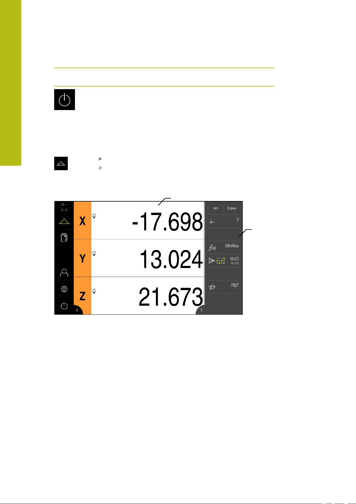
6
1
2
Basic operation | User interface
Operating
element
6.8.3 Measure menu
Activation
Short description
Function
Switch-off
Shutdown of the operating system or activation of energysaving mode
Further information: "Switch-off menu", Page 66
Tap Measure in the main menu
The user interface for measuring and positioning appears
Figure 12: Measure menu
1
The workspace shows the current position of the measuring plate
2
The Inspector contains the quick access menu and the function elements
62
HEIDENHAIN | GAGE-CHEK 2000 | Operating Instructions | 12/2018
Page 63

Basic operation | User interface
1
2
6.8.4 File management menu
Activation
Tap File management in the main menu
The user interface for file management is displayed
Short description
6
Figure 13: File management menu
1
List of available storage locations
2
List of folders in the selected storage location
The File management menu shows an overview of the files stored in the unit’s
memory.
Any connected USB mass storage devices (FAT32 format) or available network
drives are shown in the list of storage locations. The USB mass storage devices
and the network drives are displayed with their names or drive designations.
Further information: "File management", Page 147
HEIDENHAIN | GAGE-CHEK 2000 | Operating Instructions | 12/2018
63
Page 64

6
1
2
Basic operation | User interface
6.8.5 User login menu
Activation
Tap User login in the main menu
The user interface for user login and logout is displayed
Short description
Figure 14: User login menu
1
Display of the logged-in user
2
User login
The User login menu shows the logged-in user in the column on the left. The login
of a new user is displayed in the right-hand column.
To log in another user, the logged-in user must first log out.
Further information: "User login and logout", Page 57
64
HEIDENHAIN | GAGE-CHEK 2000 | Operating Instructions | 12/2018
Page 65

Basic operation | User interface
1 2
6.8.6 Settings menu
Activation
Tap Settings in the main menu
The user interface for the product settings is displayed
Short description
6
Figure 15: Settings menu
1
List of setting options
2
List of setting parameters
The Settings menu shows all options for configuring the product. With the setting
parameters, you can adapt the product to on-site requirements.
Further information: "Settings", Page 155
The product provides various authorization levels that grant the user full
or restricted access to management and operation functionality.
HEIDENHAIN | GAGE-CHEK 2000 | Operating Instructions | 12/2018
65
Page 66

6
X
R
R
Basic operation | User interface
6.8.7 Switch-off menu
Activation
Tap Switch off in the main menu
The operating elements for shutting down the operating
system, for activating the energy-saving mode and for
activating the cleaning mode are displayed
Short description
The Switch off menu provides the following options:
Operating
element
Further information: "GAGE-CHEK 2000 – switch-on and switch-off", Page 56
Further information: "Cleaning the screen", Page 192
Function
Shut down
Shuts down the operating system
Energy saving mode
Switches the screen off and puts the operating system into
energy-saving mode
Cleaning mode
Switches the screen off; the operating system continues
unchanged
6.9 Position display
The unit’s position display shows the axis positions and additional information
about the configured axes (if applicable).
6.9.1 Operating elements of the position display
Symbol Meaning
Axis key
Axis key functions:
Tapping the axis key: Opens the input field for position value
Holding down the axis key: sets the current position as zero
point
Reference mark search performed successfully
Reference mark search not performed or no reference mark
detected
66
HEIDENHAIN | GAGE-CHEK 2000 | Operating Instructions | 12/2018
Page 67

Basic operation | Working in the workspace
Symbol Meaning
Minimum: Lowest measured value (if the MinMax function is
active)
Maximum: Highest measured value (if the MinMax function is
active)
Range: Difference between the maximum and minimum (if the
MinMax function is active)
6.10 Working in the workspace
The workspace is only available in the Measure menu.
6
Activation
Tap Measure in the main menu
The user interface for measuring and positioning appears
6.10.1 Adjusting the display of the workspace
In the Measure menu, you can enlarge the workspace by hiding the main menu or
the Inspector.
Hiding and showing the main menu
Tap the tab
The main menu is hidden
The arrow changes direction
To show the main menu, tap the tab again
Hiding or displaying the Inspector
Tap the tab
The Inspector is hidden
The arrow changes direction
To display the Inspector, tap the tab
HEIDENHAIN | GAGE-CHEK 2000 | Operating Instructions | 12/2018
67
Page 68

6
Basic operation | Using the Inspector
6.11 Using the Inspector
The Inspector is only available in the Measure menu.
Activation
Tap Measure in the main menu
The user interface for measuring and positioning appears
6.11.1 Operating elements of the Inspector
The Inspector contains the following areas and operating elements:
Operating
element
Short description
Quick access menu
The quick access menu displays the current settings:
Further information: "Adjusting settings in the quick
access menu", Page 69
6.11.2 Function elements
Function elements are operating elements that you can add to the Inspector and
configure individually.
The following function elements are available:
Function element Short description
Presets
Display of the current preset; tapping opens the preset
table
Further information: "Activating the preset", Page 140
Unit for linear values (Millimeters or Inch)
Unit for angular values (Radian, Decimal degrees, or
Deg-Min-Sec)
To adjust the settings of the quick access menu, tap the
quick access menu
68
Calculator
Tapping opens a calculator with basic mathematical
functions, the last result is shown in the calculator and the
Inspector
Reference mark search (REF)
Tapping starts the reference mark search
MinMax
Captures the minimum, maximum, and range; tapping
starts the capture of measured values according to the
configuration
Further information: "Capturing the minimum, maximum,
and range", Page 144
HEIDENHAIN | GAGE-CHEK 2000 | Operating Instructions | 12/2018
Page 69

Basic operation | Using the Inspector
Function element Short description
Manual output of measured values
Send measured values to computer; tapping starts the data
transfer according to the configuration
Further information: "Sending measured values to a
computer", Page 145
Touch-probe triggered output of measured values
Send measured values to computer; tapping activates the
automatic output of measured values according to the
configuration; the data is transferred when the stylus is
deflected
Further information: "Sending measured values to a
computer", Page 145
Continuous output of measured values
Send measured values to computer; tapping activates the
automatic output of measured values according to the
configuration; the data is transferred continuously at intervals of approx. 200 ms
Further information: "Sending measured values to a
computer", Page 145
6
6.11.3 Adjusting settings in the quick access menu
With the quick access menu, you can adjust the following settings:
Unit for linear values (Millimeters or Inch)
Unit for angular values (Radian, Decimal degrees or Deg-Min-Sec)
Setting the units of measure
Before you start measuring, you need to set the desired units of measure in the
Inspector's quick access menu.
Tap the Quick access menu in the Inspector
Select the desired Unit for linear values
Select the desired Unit for angular values
Tap Close to close the quick access menu
The selected units are displayed in the quick access menu
HEIDENHAIN | GAGE-CHEK 2000 | Operating Instructions | 12/2018
69
Page 70

6
1
2
3
Basic operation | Messages and audio feedback
6.12 Messages and audio feedback
6.12.1 Messages
Figure 16: Display of messages in the workspace
1
Message display area, which displays the time and the number of unclosed
messages
2
Message list
The messages that appear at the top of the workspace are triggered by, for
example, operator errors or uncompleted processes.
The messages are displayed upon occurrence of the message cause or when you
tap the Messages display area at the top left of the screen.
Viewing messages
Tap Messages
The message list opens
Resizing the display area
To resize the message display area, drag the handle up or
down
To close the display area, drag the handle up out of the
screen
The number of unclosed messages is indicated in Messages
70
HEIDENHAIN | GAGE-CHEK 2000 | Operating Instructions | 12/2018
Page 71

Basic operation | Messages and audio feedback
1
Closing messages
Depending on the content of the messages, you can close messages by means of
the following operating elements:
To close an informational message, tap Close
The message disappears
or
To close a message that potentially has an effect on the
application, tap OK
If applicable, the message will now be taken into account by
the application
The message disappears
6.12.2 Wizard
6
Figure 17: Display of messages in the wizards
1
Wizard (example)
The wizard assists you in performing work steps or teach-in processes, and in
executing programs.
You can move the wizard in the workspace .
The following operating elements provided by the wizard depend on the work step
or process:
To return to the last work step or repeat the process, tap
Undo
To confirm the displayed work step, tap Confirm
The wizard proceeds to the next step or concludes the
process
Tap Close to close the wizard
HEIDENHAIN | GAGE-CHEK 2000 | Operating Instructions | 12/2018
71
Page 72

6
Basic operation | Messages and audio feedback
6.12.3 Audio feedback
The product can provide audio feedback to indicate user actions, completed
processes or malfunctions.
The available sounds are grouped into categories. The sounds differ within a
category.
You can define the audio feedback settings in the Settings menu.
Further information: "Sounds", Page 160
72
HEIDENHAIN | GAGE-CHEK 2000 | Operating Instructions | 12/2018
Page 73

7
Commissioning
Page 74

7
Commissioning | Overview
7.1 Overview
This chapter contains all the information necessary for commissioning the product.
During commissioning, the machine manufacturer's commissioning engineer
(OEM) configures the product for use on the specific measuring machine.
The settings can be reset to the factory defaults.
Further information: "Reset", Page 187
Make sure that you have read and understood the "Basic operation"
chapter before carrying out the actions described below.
Further information: "Basic operation", Page 51
The following steps must be performed only by qualified personnel.
Further information: "Personnel qualification", Page 23
7.2 Logging in for commissioning
7.2.1 User login
To commission the product, the OEM user must log in.
Tap User login in the main menu
If required, log out the user who is currently logged in
Select the OEM user
Tap the Password input field
Enter the password "oem"
If the password does not match the default
password, ask a Setup user or OEM user for the
assigned password.
If the password is no longer known, contact a
HEIDENHAIN service agency.
Confirm the entry with RET
Tap Log in
The user is logged in
The product opens the Measure menu
74
HEIDENHAIN | GAGE-CHEK 2000 | Operating Instructions | 12/2018
Page 75

Commissioning | Logging in for commissioning
7.2.2 Performing the reference mark search after startup
If the reference mark search after unit start is active, then all of the
unit’s functions will be disabled until the reference mark search has
been successfully completed.
Further information: "Reference marks (Encoder)", Page 182
The reference mark search does not need to be performed for serial
encoders with EnDat interface, because the axes are automatically
homed.
If the reference mark search is active on the unit, then a wizard will ask you to
traverse the reference marks of the axes.
After logging in, follow the instructions of the wizard
The Reference symbol stops blinking upon successful completion of the
reference mark search
Further information: "Operating elements of the position display", Page 66
Further information: "Activating the reference mark search", Page 83
7
7.2.3 Setting the language
The default language for the user interface is English. You can switch the user
interface to the desired language.
Tap Settings in the main menu
Tap User
The logged-in user is indicated by a check mark
Select the logged-in user
The language selected for the user is indicated by a national
flag in the Language drop-down list
Select the flag for the desired language in the Language
drop-down list
The user interface is displayed in the selected language
HEIDENHAIN | GAGE-CHEK 2000 | Operating Instructions | 12/2018
75
Page 76

7
Commissioning | Logging in for commissioning
7.2.4 Changing the password
You must change the password to prevent unauthorized configuration.
The password is confidential and must not be disclosed to any other person.
Tap Settings in the main menu
Tap User
The logged-in user is indicated by a check mark
Select the logged-in user
Tap Password
Enter the current password
Confirm entry with RET
Enter the new password and repeat it
Confirm entry with RET
Tap OK
Close the message with OK
The new password is available the next time the user logs in
7.3 Steps for commissioning
NOTICE
Loss of or damage to configuration data!
If the product is disconnected from the power source while it is on, the
configuration data can be lost or corrupted.
Back up the configuration data and keep the backup for recovery purposes
7.3.1 Basic settings
Setting the date and time
Tap Settings in the main menu
Tap General
Tap Date and time
The set values are displayed in the following format: Year,
month, day, hour, minute
To set the date and time in the middle line, drag the columns
up or down
Tap Set to confirm
Select the desired format in the Date format list:
MM-DD-YYYY: Display as month, day, year
DD-MM-YYYY: Display as day, month, year
YYYY-MM-DD: Display as year, month, day
76
Further information: "Date and time", Page 162
HEIDENHAIN | GAGE-CHEK 2000 | Operating Instructions | 12/2018
Page 77

Commissioning | Steps for commissioning
Setting the units of measure
You can set various parameters to define the units of measure, rounding methods
and decimal places.
Tap Settings in the main menu
Tap General
Tap Units
To set a unit of measure, tap the corresponding drop-down
list and select the unit
To set the rounding method, tap the corresponding drop-
down list and select the rounding method
To set the number of decimal places displayed, tap – or +
Further information: "Units", Page 163
7
HEIDENHAIN | GAGE-CHEK 2000 | Operating Instructions | 12/2018
77
Page 78

7
Commissioning | Steps for commissioning
Activating the Software options
Additional Software options can be enabled on the unit via a License key.
You can view the enabled Software options on the overview page.
Further information: "Checking the Software options", Page 80
Requesting license key
You can request a license key by using the following procedure:
Reading out device information for the license key request
Creating a license key request
Reading out device information for the license key request
Tap Settings in the main menu
Tap General
Tap Device information
An overview of the device information appears
The product designation, ID number, serial number, and
firmware version are displayed
Contact a HEIDENHAIN service agency and submit the
displayed device information in order to request a license key
for the product
The license key and the license file are generated and sent by
e-mail
78
HEIDENHAIN | GAGE-CHEK 2000 | Operating Instructions | 12/2018
Page 79

Commissioning | Steps for commissioning
Creating a license key request
Tap Settings in the main menu
Tap Service
Tap Software options
To request a software option that is available for a fee, tap
Request options
To request a free trial option, tap Request trial options
Select the desired software option
Tap Creating a request
In the dialog, select the storage location in which you want to
save the license key request
Enter a suitable file name
Confirm entry with RET
Tap Save as
The license key request is created and saved in the selected
folder
If the license key request is stored on the unit, move the file
to a connected USB mass storage device (FAT32 format) or
to the network drive
Further information: "Moving a file", Page 150
Contact a HEIDENHAIN service agency and submit the file
you created in order to request a license key for the product
The license key and the license file are generated and sent by
e-mail
7
To deselect an entry, tap the check mark for
the respective software option
Activating a license key
You can activate a license key by
Reading the license key from the provided license file into the product
Entering the license key manually into the product
HEIDENHAIN | GAGE-CHEK 2000 | Operating Instructions | 12/2018
79
Page 80

7
Commissioning | Steps for commissioning
Uploading license key from license file
Tap Settings in the main menu
Tap Service
Open in the sequence
Software options
Activate options
Tap Read license file
Select the license file in the file system, on the USB mass
storage device or on the network drive
Confirm your selection with Select
Tap OK
The license key is activated
Tap OK
You may need to restart the product, depending on the
software option
Confirm the restart with OK
The activated software option is available
Entering license key manually
Tap Settings in the main menu
Tap Service
Open in the sequence
Software options
Activate options
Enter the license key into the License key input field
Confirm the entry with RET
Tap OK
The license key is activated
Tap OK
You may need to restart the product, depending on the
software option
Confirm the restart with OK
The activated software option is available
Checking the Software options
On the overview page, you can check which Software options are enabled for the
product.
80
Tap Settings in the main menu
Tap Service
Open in the sequence
Software options
Overview
A list of enabled Software options is displayed
HEIDENHAIN | GAGE-CHEK 2000 | Operating Instructions | 12/2018
Page 81

Commissioning | Steps for commissioning
7.3.2 Configuring the axes
The procedure varies depending on the interface type of the connected encoder:
Encoders with EnDat interface:
The encoder applies the parameters automatically
Further information: "Configuring axes for encoders with EnDat interface",
Page 81
Encoders with 1 VPP or 11 µAPP or TTL interface:
The parameters must be configured manually
For the parameters of HEIDENHAIN encoders that are typically connected to the
product, refer to the overview of typical encoders.
Further information: "Overview of typical encoders", Page 88
Configuring axes for encoders with EnDat interface
If the corresponding encoder input has already been assigned to an axis, a
connected encoder with EnDat interface is automatically detected upon restart,
and the settings are adapted. Alternatively, you can assign the encoder input after
you have connected the encoder.
Requirement: An encoder with EnDat interface is connected to the product.
7
The configuration procedure is the same for each axis. The following
section describes only the configuration of the X axis.
Tap Settings in the main menu
HEIDENHAIN | GAGE-CHEK 2000 | Operating Instructions | 12/2018
81
Page 82

7
Commissioning | Steps for commissioning
Tap Axes
Tap X or, if applicable, Not defined
If applicable, select the name of the axis in the Axis name
drop-down list
Tap Encoder
Specify the connection for the corresponding encoder in the
Encoder input drop-down list:
X1
X2
X3
The available encoder information is transmitted to the
product
The settings are updated
For encoders with an EnDat 2.2 interface: If the
corresponding encoder input has already been
assigned to an axis in the device settings, then the
encoder is automatically detected upon restart, and
the settings are adapted. Alternatively, you can assign
the encoder input after you have connected the
encoder.
Select the type of encoder in the Encoder model drop-down
list:
Linear encoder
Angle encoder
Angle encoder as linear encoder
If Angle encoder as linear encoder is selected, enter the
Mechanical ratio
Tap Reference point displacement
Use the ON/OFF slide switch to activate or deactivate
Reference point displacement (calculation of the offset
between the reference mark and the machine zero point)
If activated, enter the offset value for Reference point
displacement
Confirm the entry with RET
As an alternative, you can tap Apply in Current position for
reference point shift in order to apply the current position
as the offset value
To switch to the previous display, tap Back
To view the electronic ID label of the encoder, tap
Identification label
In order to see the results of the encoder diagnosis, tap
Diagnosis
82
Further information: "Axes X, Y ...", Page 177
HEIDENHAIN | GAGE-CHEK 2000 | Operating Instructions | 12/2018
Page 83

Commissioning | Steps for commissioning
Activating the reference mark search
The product uses the reference marks to reference the machine table to the
machine, for example. If the reference mark search has been activated, a wizard
appears on startup of the product and asks the user to move the axes for the
reference mark search.
Requirement: The installed encoders have reference marks that have been
configured in the axis parameters.
The reference mark search does not need to be performed for serial
encoders with EnDat interface, because the axes are automatically
homed.
The automatic reference mark search on startup of the product can be
canceled depending on the configuration.
Further information: "Reference marks (Encoder)", Page 182
7
Tap Settings in the main menu
Tap Axes
Open in the sequence
General settings
Reference marks
Use the ON/OFF sliding switch to activate Reference mark
search after unit start
The reference marks must be traversed every time the
product is started
The functions of the product will only be available after the
reference mark search has been completed
The Reference symbol stops blinking upon successful
completion of the reference mark search
Further information: "Operating elements of the position
display", Page 66
HEIDENHAIN | GAGE-CHEK 2000 | Operating Instructions | 12/2018
83
Page 84

7
Commissioning | Steps for commissioning
Configuring the axes for encoders with 1 VPP or 11 µAPP interface
The configuration procedure is the same for each axis. The following
section describes only the configuration of the X axis.
Tap Settings in the main menu
Tap Axes
Tap X or, if applicable, Not defined
If applicable, select the name of the axis in the Axis name
drop-down list
Tap Encoder
Specify the connection for the corresponding encoder in the
Encoder input drop-down list:
X1
X2
X3
Select the type of incremental signal in the Incremental
signal drop-down list:
1 Vpp: Sinusoidal voltage signal
11 µApp: Sinusoidal current signal
Select the type of encoder in the Encoder model drop-down
list:
Linear encoder: Linear axis
Angle encoder: Rotary axis
Angle encoder as linear encoder: Rotary axis is
displayed as linear axis
Depending on the selection, enter further parameters:
For Linear encoder, enter the Signal period
(see " Linear encoders", Page 88)
For Angle encoder, enter the Line count (see "Angle
encoders", Page 90)
For an Angle encoder as linear encoder, enter the Line
count and the Mechanical ratio
Confirm the entry with RET
Tap Reference marks
Select the reference mark in the Reference mark drop-down
list:
None: There is no reference mark
One: The encoder has one reference mark
Coded: The encoder has distance-coded reference marks
If the linear encoder has coded reference marks, enter the
Maximum traverse path
(see " Linear encoders", Page 88)
If the angle encoder has coded reference marks, enter the
parameter for the Nominal increment (see "Angle encoders",
Page 90)
Confirm the entry with RET
84
HEIDENHAIN | GAGE-CHEK 2000 | Operating Instructions | 12/2018
Page 85

Commissioning | Steps for commissioning
Use the ON/OFF sliding switch to activate or deactivate
Inversion of reference mark pulses
Tap Reference point displacement
Use the ON/OFF slide switch to activate or deactivate
Reference point displacement (calculation of the offset
between the reference mark and the machine zero point)
If activated, enter the offset value for Reference point
displacement
Confirm the entry with RET
As an alternative, you can tap Apply in Current position for
reference point shift in order to apply the current position
as the offset value
In order to switch to the previous display, tap Back twice
In the Analog filter frequency drop-down list, select
the frequency of the low-pass filter for suppressing highfrequency interference signals:
33 kHz: Interference frequencies above 33 kHz
400 kHz: Interference frequencies above 400 kHz
Use the ON/OFF sliding switch to activate or deactivate the
Terminating resistor
7
The terminating resistor is automatically deactivated
for incremental signals of the current signal type
(11 μAPP)
Select the type of error monitoring in the Error monitor
drop-down list:
Off: Error monitoring not active
Amplitude: Error monitoring of signal amplitude
Frequency: Error monitoring of signal frequency
Frequency & amplitude: Error monitoring of signal
amplitude and signal frequency
Select the desired counting direction in the Counting
direction drop-down list:
Positive: The direction of traverse is in the counting
direction of the encoder
Negative: The direction of traverse is opposite to the
counting direction of the encoder
Further information: "Axes X, Y ...", Page 177
HEIDENHAIN | GAGE-CHEK 2000 | Operating Instructions | 12/2018
85
Page 86

7
Commissioning | Steps for commissioning
Configuring axes for encoders with TTL interface
The configuration procedure is the same for each axis. The following
section describes only the configuration of the X axis.
Tap Settings in the main menu
Tap Axes
Tap X or, if applicable, Not defined
If applicable, select the name of the axis in the Axis name
drop-down list
Tap Encoder
Specify the connection for the corresponding encoder in the
Encoder input drop-down list:
X21
X22
X23
Select the type of encoder in the Encoder model drop-down
list:
Linear encoder: Linear axis
Angle encoder: Rotary axis
Angle encoder as linear encoder: Rotary axis is
displayed as linear axis
Depending on the selection, enter further parameters:
For Linear encoder, enter the Signal period
(see " Linear encoders", Page 88)
For Angle encoder, enter the Output signals per
revolution (see "Angle encoders", Page 90)
For an Angle encoder as linear encoder, enter the
Output signals per revolution and the Mechanical ratio
Confirm the entry with RET
In the Interpolation drop-down list, select the type of
interpolation:
None
2-fold
5-fold
10-fold
20-fold
50-fold
Tap Reference marks
Select the reference mark in the Reference mark drop-down
list:
None: There is no reference mark
One: The encoder has one reference mark
Coded: The encoder has distance-coded reference marks
Reverse coded: The encoder has inverse-coded reference
marks
86
HEIDENHAIN | GAGE-CHEK 2000 | Operating Instructions | 12/2018
Page 87

Commissioning | Steps for commissioning
If the linear encoder has coded reference marks, enter
the Maximum traverse path (see " Linear encoders",
Page 88)
If the angle encoder has coded reference marks, enter the
parameter for the Nominal increment (see "Angle encoders",
Page 90)
Confirm the entry with RET
Use the ON/OFF sliding switch to activate or deactivate
Inversion of reference mark pulses
Tap Reference point displacement
Use the ON/OFF slide switch to activate or deactivate
Reference point displacement (calculation of the offset
between the reference mark and the machine zero point)
If activated, enter the offset value for Reference point
displacement
Confirm the entry with RET
As an alternative, you can tap Apply in Current position for
reference point shift in order to apply the current position
as the offset value
In order to switch to the previous display, tap Back twice
Use the ON/OFF sliding switch to activate or deactivate the
Terminating resistor
Select the type of error monitoring in the Error monitor
drop-down list:
Off: Error monitoring not active
Frequency: Error monitoring of signal frequency
Select the desired counting direction in the Counting
direction drop-down list:
Positive: The direction of traverse is in the counting
direction of the encoder
Negative: The direction of traverse is opposite to the
counting direction of the encoder
7
Further information: "Axes X, Y ...", Page 177
HEIDENHAIN | GAGE-CHEK 2000 | Operating Instructions | 12/2018
87
Page 88

7
Commissioning | Steps for commissioning
Overview of typical encoders
The following overview lists the parameters of the HEIDENHAIN encoders that are
typically connected to the product.
When connecting other encoders, refer to the encoder's
documentation for the required parameters.
Linear encoders
Encoder series Interface Signal period Reference mark Maximum
traverse path
LS 328C TTL
AK LIDA 27 TTL
20 μm
20 μm
4 μm
2 μm
AK LIDA 47 TTL
4 μm
4 μm
2 μm
2 μm
LS 388C 1 V
AK LIDA 28 1 V
AK LIDA 48 1 V
AK LIF 48 1 V
*)
“Coded / 1000” only in conjunction with the LIDA 4x3C scale
PP
PP
PP
PP
20 μm
200 μm
20 μm
4 μm
Coded / 1000 20 mm
One -
One -
Coded / 1000
*)
20 mm
One -
Coded / 1000
*)
20 mm
Coded / 1000 20 mm
One -
One -
One -
88
HEIDENHAIN | GAGE-CHEK 2000 | Operating Instructions | 12/2018
Page 89

Commissioning | Steps for commissioning
Length gauges
7
Length
Interface Signal period Reference mark Maximum
gaugeseries
CT 250x
CT 600x
11 μA
11 μA
PP
PP
MT 1271 TTL
MT 128x 1 V
PP
MT 2571 TTL
MT 258x 1 V
MT 60x
MT 101x
PP
11 μA
11 μA
PP
PP
ST 127x TTL
ST 128x 1 V
PP
ST 307x TTL
ST 308x 1 V
*)
0.2 μm or 2 μm with 10-fold evaluation
PP
0.4 μm or 4 μm with 5-fold evaluation
2 μm
2 μm
0.4 μm, 0.2 μm
2 μ
0.4 μm, 0.2 μm
2 μm
10 μm
10 μm
4 μm, 2 μm
*)
20 μm
4 μm, 2 μm
*)
20 μm
traverse path
One 25 mm
One 60 mm
*)
One 12 mm
One 12 mm
*)
One 25 mm
One 25 mm
One 60 mm
One 100 mm
One 12 mm
One 12 mm
One 30 mm
One 30 mm
Length
gaugeseries
Interface Measuring step Maximum
traverse path
AT 121x EnDat 2.2 23 nm 12 mm
AT 301x EnDat 2.2 368 nm 30 mm
HEIDENHAIN | GAGE-CHEK 2000 | Operating Instructions | 12/2018
89
Page 90

7
Commissioning | Steps for commissioning
Angle encoders
Encoder series Interface Line count/
Reference mark Nominal
outputs signals per
revolution
RON 225 TTLx2 18000 One -
RON 285 1 V
RON 285C 1 V
RON 785 1 V
RON 785C 1 V
RON 786 1 V
RON 786C 1 V
PP
PP
PP
PP
PP
PP
18000 One -
18000 Coded 20°
18000 One -
18000 Coded 20°
18000 One -
18000 Coded 20°
ROD 220 TTLx2 18000 One -
ROD 280 1 V
ROD 280C 1 V
PP
PP
18000 One -
18000 Coded 20°
The formulae below enable you to calculate the nominal increment of
the distance-coded reference marks with angle encoders:
Nominal increment = 360° number of reference marks × 2
Nominal increment = (360° × nominal increment in signal periods) line
count
increment
Performing error compensation
Mechanical influences such as guideway error, tilting in the end positions,
mounting surface tolerances, or poor mounting (Abbe error) can cause measuring
errors. With error compensation, the unit can automatically compensate for
systematic measuring errors during measuring point acquisition. Through the
comparison of nominal and actual values, one or more compensation factors can
be defined and applied during subsequent measurements.
A distinction is made between the following methods:
Configuring error compensation for individual axes
Linear error compensation (LEC): The compensation factor is calculated based
on the specified length of a calibration standard (nominal length) and the actual
distance traversed (actual length). The compensation factor is applied linearly to
the entire measuring range.
Segmented linear error compensation (SLEC): The axis is divided into multiple
segments with the help of a maximum of 200 supporting points. A distinct
compensation factor is defined and applied for every segment.
90
HEIDENHAIN | GAGE-CHEK 2000 | Operating Instructions | 12/2018
Page 91

Commissioning | Steps for commissioning
Configuring error compensation across axes
Nonlinear error compensation (NLEC): By means of a maximum of a 99
supporting points, the measuring range is divided into a grid with multiple
subareas. For every subarea, a distinct compensation factor is determined and
applied.
Squareness error compensation: The compensation factor is determined by
comparing the nominal angle of the spatial axes with the measurement result.
The compensation factor is applied to the entire measuring range.
Subsequent modifications to the encoder settings can result in measuring
errors
If encoder settings such as the encoder input, encoder model, signal period, or
reference marks are changed, previously determined compensation factors may
no longer apply.
7
NOTICE
If the encoder settings are changed, reconfigure the error compensation
For all methods, the actual error curve must be exactly measured (e.g.,
with the help of a comparator measuring device or calibration standard).
Linear error compensation and segmented linear error compensation
cannot be combined with each other.
Configuring linear error compensation (LEC)
With linear error compensation (LEC) the product applies a compensation factor
that is calculated from the specified length of a reference standard (nominal
length) and the actual traverse path (actual length). The compensation factor is
applied to the complete measuring range.
Tap Settings in the main menu
Tap Axes
Select the axis
Open in the sequence
Error compensation
Linear error compensation (LEC)
Enter the length of the reference standard (nominal length)
Confirm the entry with RET
Enter the length of the actual traverse path determined by
measure (actual length)
Confirm the entry with RET
Activate Compensation with the ON/OFF sliding switch
Further information: "Linear error compensation (LEC)", Page 183
HEIDENHAIN | GAGE-CHEK 2000 | Operating Instructions | 12/2018
91
Page 92

7
Commissioning | Steps for commissioning
Configuring segmented linear error compensation (SLEC)
For a segmented linear error compensation (SLEC), you divide the axis into short
segments by defining up to 200 supporting points. The deviations between the
actual distance traversed and the segment length in the individual segments
determine the compensation values that compensate the mechanical influences
acting on the axis.
Tap Settings in the main menu
Tap Axes
Select the axis
Open in the sequence
Error compensation
Segmented linear error compensation (SLEC)
Deactivate Compensation with the ON/OFF sliding switch
Tap Create table of supporting points
Tap + or – to set the desired Number of supporting points
(max. 200)
Enter the desired Spacing of the supporting points
Confirm the entry with RET
Enter the Start point
Confirm the entry with RET
Tap Create to create the table of supporting points
The table of supporting points is created
The table lists the supporting point positions (P) and the
compensation values (D) of the individual segments
Enter the compensation value (D) "0.0" for supporting point 0
Confirm the entry with RET
Enter the measured compensation value into the
compensation value (D) input field for each supporting point
created
Confirm the entry with RET
To switch to the previous display, tap Back twice
Activate Compensation with the ON/OFF sliding switch
The error compensation for the axis is applied
92
Further information: "Segmented linear error compensation (SLEC)", Page 184
HEIDENHAIN | GAGE-CHEK 2000 | Operating Instructions | 12/2018
Page 93

Commissioning | Steps for commissioning
Adjusting an existing table of supporting points
After a table of supporting points for segmented linear error compensation has
been created, this table can then be modified as needed.
Tap Settings in the main menu
Tap Axes
Select the axis
Open in the sequence
Error compensation
Segmented linear error compensation (SLEC)
Deactivate Compensation with the ON/OFF sliding switch
Tap Table of supporting points
The table lists the supporting point positions (P) and the
compensation values (D) of the individual segments
Adjust the compensation value (D) for the supporting points
Confirm the entries with RET
To switch to the previous display, tap Back
Activate Compensation with the ON/OFF sliding switch
The adjusted error compensation for the axis is applied
7
Further information: "Segmented linear error compensation (SLEC)", Page 184
HEIDENHAIN | GAGE-CHEK 2000 | Operating Instructions | 12/2018
93
Page 94

7
Commissioning | Steps for commissioning
Nonlinear error compensation (NLEC)
For Nonlinear error compensation (NLEC) the measuring range is divided into a
grid by defining up to 99 supporting points. For each of the identically-sized surface
segments a specific compensation factor is determined by comparing nominal and
actual values (the measured values).
The following options are available for measuring the nominal and actual values of
the supporting points:
Create the table of supporting points manually and enter actual values
Create the table of supporting points manually and determine actual values in a
teach sequence
Read deviations of the calibration standard and enter actual values, determine
these in a teach sequence or import the values (.txt)
Import formats:
.txt format: contains actual values of the supporting points
Extended .txt format: contains deviations of the theoretical nominal value
Import a table of supporting points with nominal and actual values (.xml)
Import format
.xml format: corresponds to the standard export format of the product
If you read the deviations of a calibration standard or import a table of
supporting points and the number or distances of the supporting points
are different from the existing table of supporting points, a new table of
supporting points is generated. The original table of supporting points is
overwritten.
Tap Settings in the main menu
Open in the sequence
Axes
General settings
Error compensation
Nonlinear error compensation (NLEC)
Deactivate Compensation with the ON/OFF sliding switch
Enter the Number of supporting points for each axis
Enter the Spacing of the supporting points for each axis
To import existing calibration data, tap Read deviations of
calibration standard
Further information: "Measuring calibration data in .acf
format", Page 95
Navigate to the desired folder
Tap the desired file (.acf)
Tap Select
The calibration data of the calibration standard are read
To import a table of supporting points, tap Import table of
supporting points
Further information: "Measuring the table of supporting
points in .txt format", Page 96
Navigate to the desired folder
Tap the desired file (.xml or .txt)
94
HEIDENHAIN | GAGE-CHEK 2000 | Operating Instructions | 12/2018
Page 95

Commissioning | Steps for commissioning
Tap Select
The table of supporting points is imported
To manually adjust the table of supporting points, tap Table
of supporting points
Adjust the actual values of the axes
The start the teach sequence, tap Start
The teach sequence is started and the wizard is displayed in
the Measure menu
Follow the instructions of the wizard
Values measured in the teach sequence are adopted as
actual values in the table of supporting points
After the teach sequence is complete, the Measure menu
continues to be displayed
Recall the Nonlinear error compensation (NLEC) menu
Activate Compensation with the ON/OFF sliding switch
The error compensation is applied from the next
measurement
7
Further information: "Nonlinear error compensation (NLEC)", Page 176
Measuring calibration data in .acf format
The manufacturer of the calibration standard usually provides you with the
calibration data and specifications about the deviations. To read the calibration data
into the product you must measure these in .acf format.
Open a new file in the text editor of your computer
Save the file under a unique name and the file extension *.acf
Measure the calibration data with tab stops separated according to the
following schema
Schema of the calibration data in .acf format
Unit of measure Directional axis
Spacing of supporting points on the X
axis
Number of supporting points on the X
axis
X value of the first supporting point Y value of the first supporting point
X value of the second supporting point Y value of the second supporting point
... ...
X value of the last supporting point Y value of the last supporting point
Spacing of supporting points on the Y
axis
Number of supporting points on the Y
axis
Select either X or Y as the directional axis.
HEIDENHAIN | GAGE-CHEK 2000 | Operating Instructions | 12/2018
95
Page 96

7
Commissioning | Steps for commissioning
Example:
The example shows a grid with 5 x 5 supporting points with spacing of 25 mm on
the X axis and 20 mm on the Y axis, oriented on the X axis.
Figure 18: Example of calibration data in .acf format
Measuring the table of supporting points in .txt format
You can generate the import file for the table of supporting points in .txt format:
Open a new file in the text editor of your computer
Save the file under a unique name and the file extension *.txt
Measure the data with tab stops separated according to the following schema
Data schema in .txt format
The .txt file contains the actual values of the supporting points (in X and Y) and
must be constructed according to the following schema:
Unit of measure Directional axis
Spacing of supporting points on the X
axis
Number of supporting points on the X
axis
X value of the first supporting point Y value of the first supporting point
X value of the second supporting point Y value of the second supporting point
... ...
X value of the last supporting point Y value of the last supporting point
Spacing of supporting points on the Y
axis
Number of supporting points on the Y
axis
96
Select either X or Y as the directional axis.
HEIDENHAIN | GAGE-CHEK 2000 | Operating Instructions | 12/2018
Page 97

Commissioning | Steps for commissioning
Example:
The example shows a grid with 5 x 5 supporting points with spacing of 25 mm on
the X axis and 20 mm on the Y axis, oriented on the X axis.
7
Figure 19: Example for .txt import format
HEIDENHAIN | GAGE-CHEK 2000 | Operating Instructions | 12/2018
97
Page 98

7
Commissioning | Steps for commissioning
Data schema in extended .txt format
The .txt file contains the deviations of the supporting points (in X and Y) from their
nominal values and must be constructed according to the following schema:
NLEC Data File (required text)
0.91 (required text)
// Serial Number = xx-xxxx-xxxx-xxxx (comment, optional)
mm (unit of measure)
ON (required text)
Number of Grid Points (x, y): (required text)
x
(number of supporting points on the X
axis)
Grid Block Size (x, y): (required text)
x.x
(spacing of supporting points on the Y
axis)
Offset: (required text)
0 0
Station (x1, y1) (required text)
x.xxxx
(deviation of the first supporting point
on the X axis)
Station (x2, y1) (required text)
x.xxxx
(deviation of the second supporting
point on the X axis)
... ...
x
(number of supporting points on the Y
axis)
x.x
(spacing of supporting points on the X
axis)
x.xxxx
(deviation of the first supporting point
on the Y axis)
x.xxxx
(deviation of the second supporting
point on the Y axis)
98
HEIDENHAIN | GAGE-CHEK 2000 | Operating Instructions | 12/2018
Page 99

Commissioning | Steps for commissioning
Example:
The example shows a grid with 5 x 5 supporting points with spacing of 25 mm on
the X axis and 20 mm on the Y axis.
7
Figure 20: Example for extended .txt import format
HEIDENHAIN | GAGE-CHEK 2000 | Operating Instructions | 12/2018
99
Page 100

7
Commissioning | Steps for commissioning
Squareness error compensation (SEC)
Squareness error compensation (SEC) enables angular errors to be compensated
during measuring point acquisition. The compensation factor is determined
by comparing the deviation of the nominal angle of the spatial axes with the
actual measurement result. The compensation factor is applied to the complete
measuring range.
Tap Settings in the main menu
Open in the sequence
Axes
General settings
Error compensation
Squareness error compensation (SEC)
The measured values (M) and nominal values (S) of the three
spatial axes are displayed
Enter the measured values of the reference standard
(= nominal values)
Squareness error compensation is applied from the next
measurement
Further information: "Squareness error compensation (SEC)", Page 176
7.3.3 Configuring a touch probe
You can use a touch probe to probe points on a workpiece. The stylus of the touch
probe can be additionally fitted with a ruby ball tip. In order to use a touch probe,
you need to configure the relevant parameters.
Tap Settings in the main menu
Tap Sensors
Tap Touch probe
Use the ON/OFF sliding switch to activate or deactivate the
touch probe
Enter the length difference of the touch probe in the Length
input field
Confirm the entry with RET
Enter the stylus diameter of the touch probe in the Diameter
input field
Confirm the entry with RET
Use the touch-probe triggered output of measured values to
automatically send the measured values to a computer when the stylus
is deflected.
Further information: "Configuring the measured value output",
Page 127
100
HEIDENHAIN | GAGE-CHEK 2000 | Operating Instructions | 12/2018
 Loading...