


AVR 132
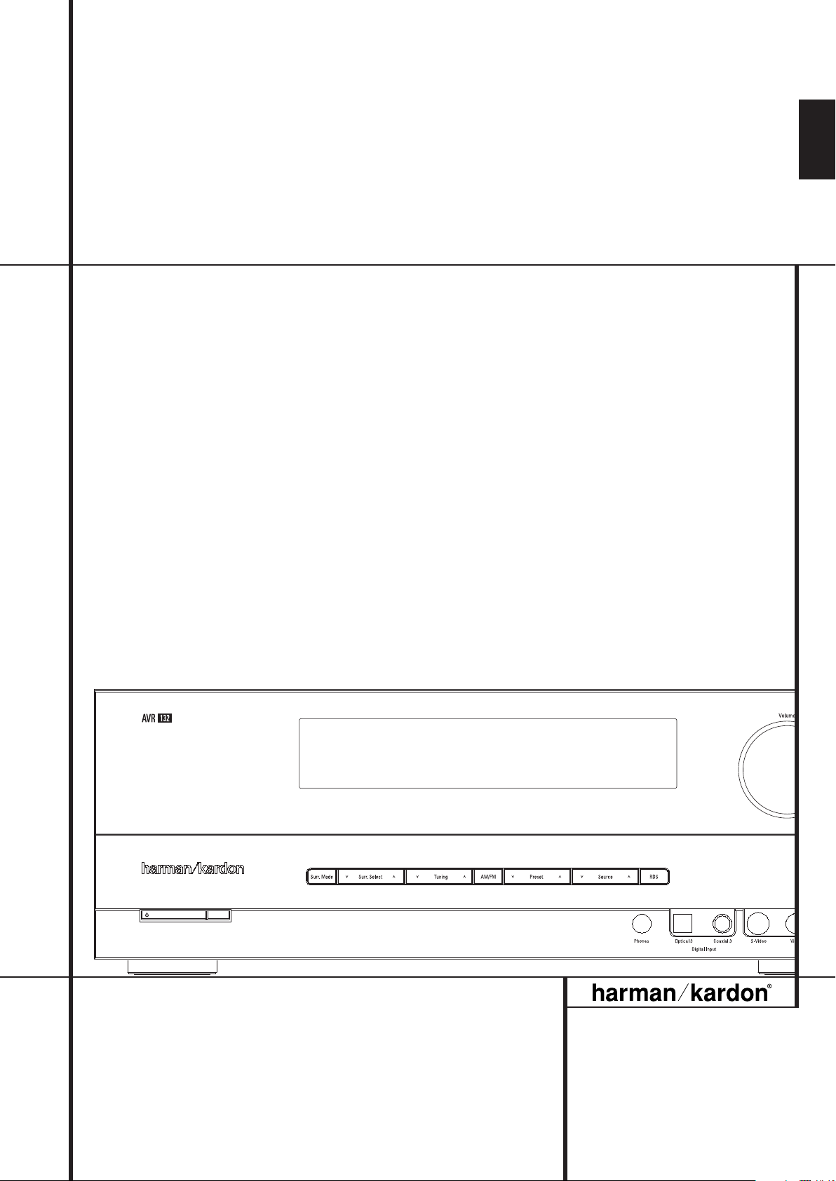
AVR 132 Audio/ VideoReceiver
OWNER’S MANUAL
ENGLISH
Table of Contents
3 Introduction
4 Safety Information
4 Unpacking
5 Front Panel Controls
7 Rear Panel Connections
9 Remote Control Functions
12 Installation and Connections
12 Audio Equipment Connections
13 Video Equipment Connections
14 SCART A/V Connections
14 AC Power Connections
15 Speaker Selection and Placement
16 System Configuration
16 First Turn On
16 Settings to be Made
With Each Input Used
16 Input Setup
16 Speaker Setup
17 Triple Crossover Setting
18 Surround Setup
18 Configuring the Surround Off
(Stereo) Modes
18 Stereo-Direct (Bypass) Mode
19 Stereo Digital Mode
19 Delay Settings
19 Night Mode Settings
19 Output Level Adjustment
21 Operation
21 Basic Operation
21 Source Selection
21 Controls and Use of Headphones
21 Surround Mode Selection
22 Surround Mode Chart
24 Digital Audio Playback
25 Selecting a Digital Source
25 Digital Status Indicators
25 Surround Mode Types
26 Night Mode
26 Tape Recording
26 Output Level Trim Adjustment
27 6-Channel Direct Input
27 Display Brigthness
27 Memory Backup
27 Tuner Operation
28 RDS Operation
29 Programming the Remote
29 Programming the Remote with Codes
29 Code Readout
30 Programmed Device Functions
30 Macro Programming
31 Volume Punch-Through
31
Channel Control Punch-Through
31 Transport Control Punch-Through
31 Resetting the Remote Memory
32 Function List
34 Troubleshooting Guide
34 Processor Reset
35 Technical Specifications
Declaration of Conformity
We, Harman Consumer Group International
2, route de Tours
72500 Château-du-Loir,
FRANCE
declare in own responsibility, that the product described in
this owner’s manual is in compliance with technical
standards:
EN 55013:2001 + A1:2003
EN 55020:2002 + A1:2003
EN 61000-3-2:2000
EN 61000-3-3:1995 + A1:2001
EN 60065:2002
Jurjen Amsterdam
Harman Consumer Group International
07/06
Typographical Conventions
In order to help you use this manual with the remote control, front-panel controls and rear-panel
connections, certain conventions have been used.
EXAMPLE – (bold type) indicates a specific remote control or front-panel button, or rear-panel
connection jack
EXAMPLE – – (OCR type) indicates a message that is visible on the front-panel information display
– (number in a square) indicates a specific front-panel control
0
– (number in a circle) indicates a rear-panel connection
0
– (number in an oval) indicates a button or indicator on the remote.
2 TABLE OF CONTENTS
Introduction
Thank you for choosing Harman Kardon!
With the purchase of a Harman Kardon
AVR 132 you are about to begin many years of
listening enjoyment. The AVR 132 has been
custom designed to provide all the excitement
and detail of movie sound tracks and every
nuance of musical selections.With onboard
Dolby* Digital and DTS
†
decoding, the AVR 132
delivers six discrete channels of audio that take
advantage of the digital sound tracks from the
latest DVD and LD releases and Digital Television
broadcasts.
While complex digital systems are hard at work
within the AVR 132 to make all of this happen,
hookup and operation are simple. Color-keyed
connections and a programmable remote control make the AVR easy to use. To obtain the
maximum enjoyment from your new receiver,
we urge you to take the time to read through
this manual. This will ensure that connections to
speakers, source playback units and other external devices are made properly. In addition, a
few minutes spent learning the functions of the
various controls will enable you to take
advantage of all the power the AVR 132 is able
to deliver.
If you have any questions about this product,
its installation or its operation, please contact
your dealer. He is your best local source of
information.
Description and Features
The AVR 132 is among the most versatile and
multi-featured A/V receivers available,
incorporating a wide range of listening options.
In addition to Dolby Digital and DTS decoding
for digital sources, a broad choice of analog
surround modes are available for use with
sources such as CD,VCR,TV broadcasts and the
AVR’s own FM/AM tuner. Along with the latest
Dolby ProLogicII
®
decoding technology, Dolby 3
Stereo, 5 Ch Stereo and custom Hall and Theater
modes, only Harman Kardon receivers offer Logic
®
7
to create a wider, more enveloping field
environment and more defined fly-overs and
pans.
In addition to providing a wide range of listening
options, the AVR 132 is easy to configure so that
it provides the best results with your speakers
and specific listening-room environment.
A Stereo-Direct mode bypasses the digital
processor to preserve all of the subtleties of
older analog, two-channel materials, while bass
management, available in the surround and
Stereo-Digital modes,improves your ability to
tailor the sound to suit your room acoustics or
taste.
For the ultimate in flexibility, the AVR 132
features connections for four video devices, all
with both composite and S-Video inputs,
including the front-panel inputs.Two additional
audio inputs are available, and a total of six
digital inputs make the AVR 132 capable of
handling all the latest digital audio sources.
A video recording output and a six-channel
input make the AVR 132 virtually future-proof,
with everything needed to accommodate
tomorrow’s new formats right on board.
The AVR 132’s powerful amplifier uses
traditional Harman Kardon high-current design
technologies to meet the wide dynamic range of
any program selection.
Harman Kardon invented the high-fidelity
receiver fifty years ago.With state-of-the-art circuitry and time-honored circuit designs, the
AVR 132 is one of the finest receivers ever
offered by Harman Kardon within its price range.
■ Onboard Dolby Digital and DTS
Decoding Using Crystal
®
Chip
Technology
■ Harman Kardon’s exclusive Logic 7
®
processing, along with a choice of
Dolby Virtual Speaker processing for
use when only two speakers are
available
■ Dolby Headphone to create spacious,
open sound fields when using headphones
■ Dolby Laboratory's latest ProLogic II
decoding technology.
■ Stereo-Direct Mode for Two-Channel
Sources Bypasses DSP Processing to
Preserve the Integrity of Analog
Materials
■ Stereo-Digital Mode for Programmable
Bass Management of Low Frequencies
Between Main Speakers and
Subwoofer
■ Front panel digital inputs for easy
connection to portable digital devices
and the latest video game consoles
■ Multiple Digital Inputs
■ 6-Channel Direct Input for Use With
DVD-Audio or SACD Players and Other
Products With Internal Surround
Decoders
■ Color-Coded Input,Output and Speaker
Terminals Comply With CEA Standards
for Easy Installation
■ Remote with Internal Codes Capability
■ High-bandwidth, HDTV-compatible
component video switching
■ Input titling for all input sources
(except tuner)
ENGLISH
INTRODUCTION 3

Safety Information
Important Safety Information
READ THIS BEFORE OPERATING
YOUR UNIT.
Do not install this equipment in a confined space
such as a case or similar – away from direct
sunlight, heat sources, vibration, dust, moisture,
and/or cold.
Avoid installing this unit where foreign object
may fall onto this unit and/or this unit may be
exposed to liquid dripping or splashing. On the
top of this unit, do not place:
– Burning objects (i.e. candles), as they may
cause fire, damage to this unit, and/or
personal injury.
– Containers with liquid in them, as they may
fall and liquid may cause electrical shock to
the user and/or damage to this unit.
Do not cover this unit with a newspaper, tablecloth, curtain, etc. in order not to obstruct heat
radiation. If the temperature inside this unit
rises, it may cause fire, damage to this unit,
and/or personal injury.
Install this unit near the AC outlet and where the
AC power plug can be reached easily.
This unit is not disconnected from the AC power
source as long as it is connected to the wall outlet, even if this unit itself is turned off. This state
is called the standby mode. In this state, this unit
is designed to consume a very small quantity of
power.
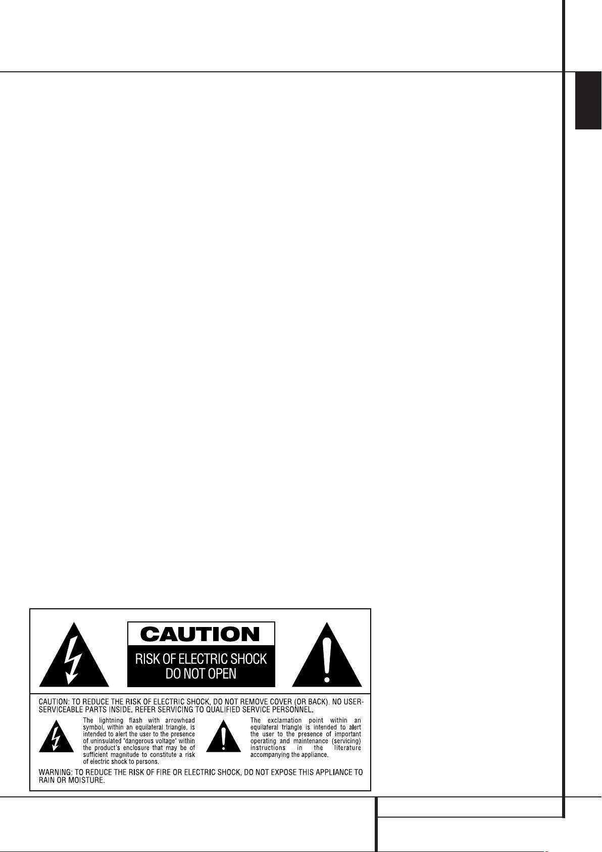
WARNING
TO REDUCE THE RISK OF FIRE OR ELECTRIC
SHOCK, DO NOT EXPOSE THIS APPLIANCE
TO RAIN OR MOISTURE.
Verify Line Voltage Before Use
Your AVR 132 has been designed for use with
220-240-Volt AC current. Connection to a line
voltage other than that for which it is intended
can create a safety and fire hazard and may
damage the unit.
If you have any questions about the voltage
requirements for your specific model, or about
the line voltage in your area, contact your dealer
before plugging the unit into a wall outlet.
Do Not Use Extension Cords
To avoid safety hazards, use only the power cord
attached to your unit. We do not recommend
that extension cords be used with this product.
As with all electrical devices, do not run power
cords under rugs or carpets or place heavy
objects on them. Damaged power cords should
be replaced immediately by an authorized service depot with a cord meeting factory specifications.
Handle the AC Power Cord Gently
When disconnecting the power cord from an AC
outlet, always pull the plug, never pull the cord.
If you do not intend to use the unit for any
considerable length of time, disconnect the plug
from the AC outlet.
Do Not Open the Cabinet
There are no user-serviceable components inside
this product. Opening the cabinet may present a
shock hazard, and any modification to the product will void your guarantee. If water or any
metal object such as a paper clip, wire or a
staple accidentally falls inside the unit, disconnect it from the AC power source immediately,
and consult an authorized service station.
Installation Location
■ To assure proper operation and to avoid the
potential for safety hazards, place the unit on
a firm and level surface.When placing the
unit on a shelf, be certain that the shelf and
any mounting hardware can support the
weight of the product.
■ Make certain that proper space is provided
both above and below the unit for ventilation.
If this product will be installed in a cabinet or
other enclosed area, make certain that there
is sufficient air movement within the cabinet.
Under some circumstances a fan may be
required.
■ Do not place the unit directly on a carpeted
surface.
■ Avoid installation in extremely hot or cold
locations, or an area that is exposed to direct
sunlight or heating equipment.
■ Avoid moist or humid locations.
■ Do not obstruct the ventilation slots on the
top of the unit, or place objects directly over
them.
Cleaning
When the unit gets dirty, wipe it with a clean,
soft, dry cloth. If necessary, wipe it with a soft
cloth dampened with mild soapy water, then a
fresh cloth with clean water. Wipe dry immediately with a dry cloth. NEVER use benzene,
aerosol cleaners, thinner, alcohol or any other
volatile cleaning agent. Do not use abrasive
cleaners, as they may damage the finish of metal
parts.Avoid spraying insecticide near the unit.
Moving the Unit
Before moving the unit, be certain to disconnect
any interconnection cords with other components, and make certain that you disconnect the
unit from the AC outlet.
Unpacking
The carton and shipping materials used to protect your new receiver during shipment were
specially designed to cushion it from shock and
vibration. We suggest that you save the carton
and packing materials for use in shipping if you
move, or should the unit ever need repair.
To minimize the size of the carton in storage,
you may wish to flatten it. This is done by carefully slitting the tape seams on the bottom and
collapsing the carton. Other cardboard inserts
may be stored in the same manner. Packing
materials that cannot be collapsed should be
saved along with the carton in a plastic bag.
If you do not wish to save the packaging materials, please note that the carton and other sections of the shipping protection are recyclable.
Please respect the environment and discard
those materials at a local recycling center.
4 SAFETY INFORMATION
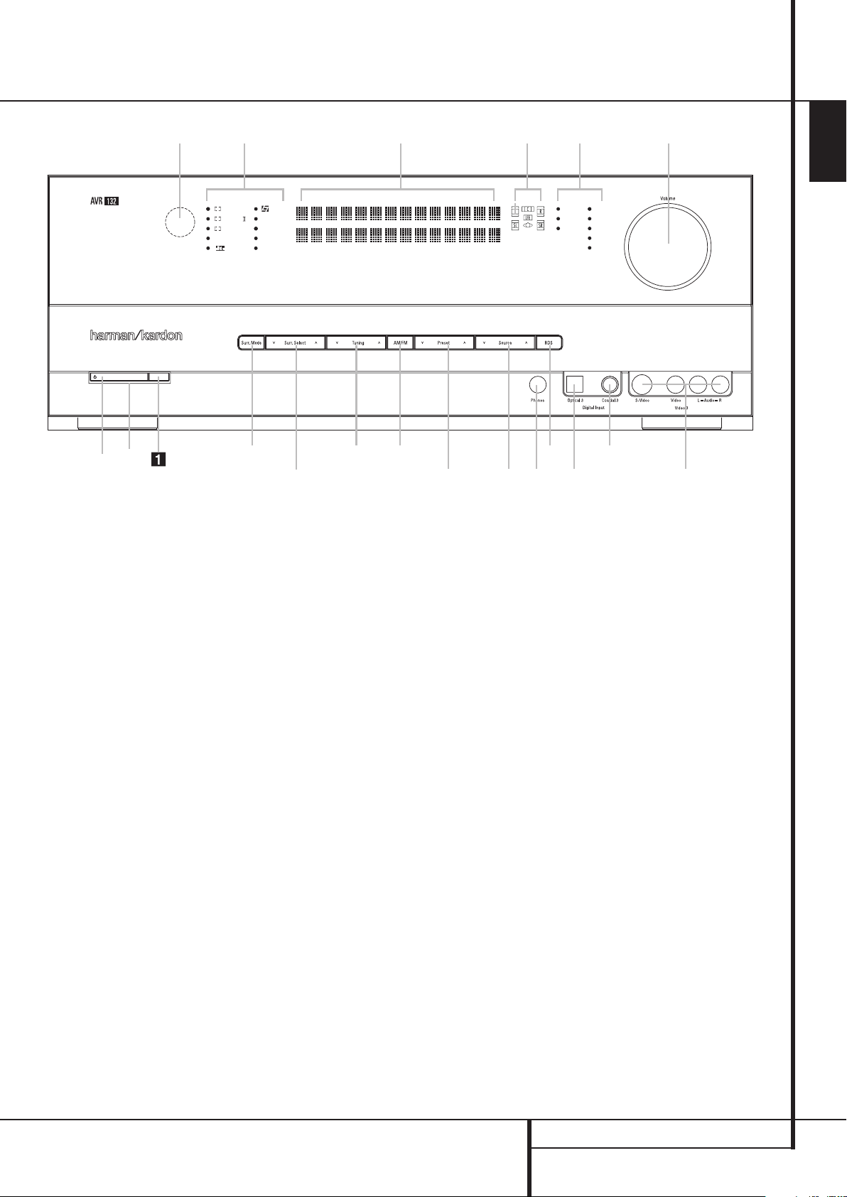
Front Panel Controls
1
67
G
9
D
F
I
J
C
8
B
H
2
4
A
5
E
3
DIGITAL LOGIC 7
VID 1 DVD
CD
FMAM
TAPE
VID 2
VID 3
PRO LOGIC
3 STEREO DSP
5 CH. STEREO
SURR. OFF
6 CH
ENGLISH
Main Power Switch
1
System Power Control
2
Power Indicator
3
Headphone Jack
4
Digital Optical 3 Input
5
Speaker/Channel Input Indicator
6
Surround Mode Group Selector
Main Power Switch: Press this button to
apply power to the AVR. When the switch is
pressed in, the unit is placed in a Standby
mode, as indicated by the orange LED
2
. This
button MUST be pressed in to operate the unit.
To turn the unit off completely and prevent the
use of the remote control, this switch should be
pressed until it pops out from the front panel
so that the word “OFF” may be read at the top
of the switch.
NOTE: This switch is normally left in the “ON”
position.
7
Tuning
8
Tuner Band Selector
9
Preset Stations Selector
A
Input Source Selector
B
RDS Select Button
C
Surround Mode Selector
D
Surround Mode Indicators
1
System Power Control: When the Main
Power Switch
is “ON,” press this button to
turn on the AVR; press it again to turn the unit
off (to Standby). Note that the Power
Indicator
2
nated in orange when the unit is in the Standby
2
will turn blue when the unit is on.
Power Indicator: This LED will be illumi-
mode to signal that the unit is ready to be
turned on. When the unit is in operation, the
indicator will turn blue.
3
Headphone Jack: This jack may be used to
listen to the AVR’s output through a pair of
headphones. Be certain that the headphones
have a standard 6.3 mm stereo phone plug.
Note that the speakers will automatically be
turned off when the headphones are connected.
4
Digital Optical 3 Input: Connect the optical digital audio output of an audio or video product to this jack. When the Input is not in use, be
certain to keep the plastic cap installed to avoid
dust contamination that might degrade future
performance.
E
Remote Sensor Window
F
Main Information Display
G
Digital Coax 3 Input
H
Video 3 input jacks
I
Volume Control
J
Input Indicators
5
Speaker/Channel Input Indicators: These
indicators are multipurpose, indicating either the
speaker type selected for each channel or the
incoming data-signal configuration.The left, center, right, right surround and left surround speaker
indicators are composed of three boxes, while the
subwoofer is a single box. The center box lights
when a “Small” speaker is selected, and the two
outer boxes light when “Large” speakers are
selected. When none of the boxes are lit for the
center, surround or subwoofer channels,no
speaker has been selected for that position. (See
page 16 for more information on configuring
speakers.) The letters inside each of the center
boxes display active input channels. For standard
analog inputs, only the L and R will light,indicating a stereo input. When a digital source is playing, the indicators will light to display the channels begin received at the digital input. When the
letters flash, the digital input has been interrupted. (See page 20 for more information on the
Channel Indicators).
FRONT PANEL CONTROLS 5

•
¡
™
Front Panel Controls
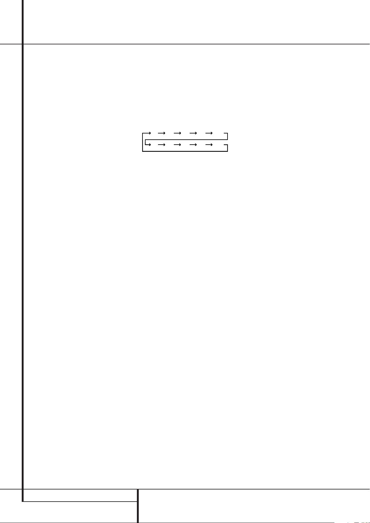
6
Surround Mode Group Selector: Press
this button to select the top-level group of
surround modes. Each press of the button will
select a major mode grouping in the following
order:
Dolby Modes ➜ DTS Digital Modes ➜ DSP
Modes ➜ Stereo Modes ➜ Logic 7 Modes
Once the button is pressed so that the name of
the desired surround mode group appears in the
Lower Display Line
Mode Selector
vidual modes available. For example, press this
button to select Dolby modes, and then press
the Surround Mode Selector
from the various mode options.
7
Tuning Selector: Press the left side of the
button to tune lower frequency stations and the
right side of the button to tune higher frequency
stations.When a station with a strong signal is
reached,
MANUAL TUNED or AUTO
TUNED
Display
on tuning stations).
8
will automatically switch the AVR to the Tuner
mode. Pressing it again will switch between the
AM and FM frequency bands, holding it pressed
for some seconds will switch between stereo
and mono receiving and between automatic and
manual tuning mode (See page 27 for more
information on the tuner).
will appear in the Main Information
F
(see page 27 for more information
Tuner Band Selector: Pressing this button
F
, press the Surround
C
to cycle through the indi-
C
to choose
9
Preset Stations Selector: Press this
button to scroll up or down through the list of
stations that have been entered into the preset
memory. (See page 27 for more information on
tuner programming.)
A
Input Source Selector: Press this button
to change the input by scrolling through the list
of input sources.
B
RDS Select Button: Press this button to
display the various messages that are part of the
RDS data system of the AVR’s tuner. (See page 28
for more information on RDS).
C
Surround Mode Selector: Press this button to select from among the available surround
mode options for the mode group selected. The
specific modes will vary based on the number of
speakers available, the mode group and if the
input source is digital or analog. For example,
press the Surround Mode Group Selector
6
to select a mode grouping such as Dolby or
Logic 7, and then press this button to see the
mode choices available. For more information on
mode selection, see page 21.
D
Surround Mode Indicators: Indicator will
illuminate in front of the surround mode that is
currently in use.
E
Remote Sensor Window:The sensor
behind this window receives infrared signals
from the remote control. Aim the remote at this
area and do not block or cover it unless an
external remote sensor is installed.
F
Main Information Display: This display
delivers messages and status indications to help
you operate the receiver.
G
Digital Coax 3 Input: This jack is normally
used for connection to the output of portable
digital audio devices, video game consoles or
other products that have a coax digital jack.
H
Video 3 Input Jacks: These audio/video
jacks may be used for temporary connection to
video games or portable audio/video products
such as camcorders and portable audio players.
I
Volume Control:Turn this knob clockwise
to increase the volume, counterclockwise to
decrease the volume. If the AVR is muted,
adjusting volume control will automatically
release the unit from the silenced condition.
J
Input indicators: Indicator will illuminate
in front of the input that is currently being used
as the source for the AVR.
6 FRONT PANEL CONTROLS
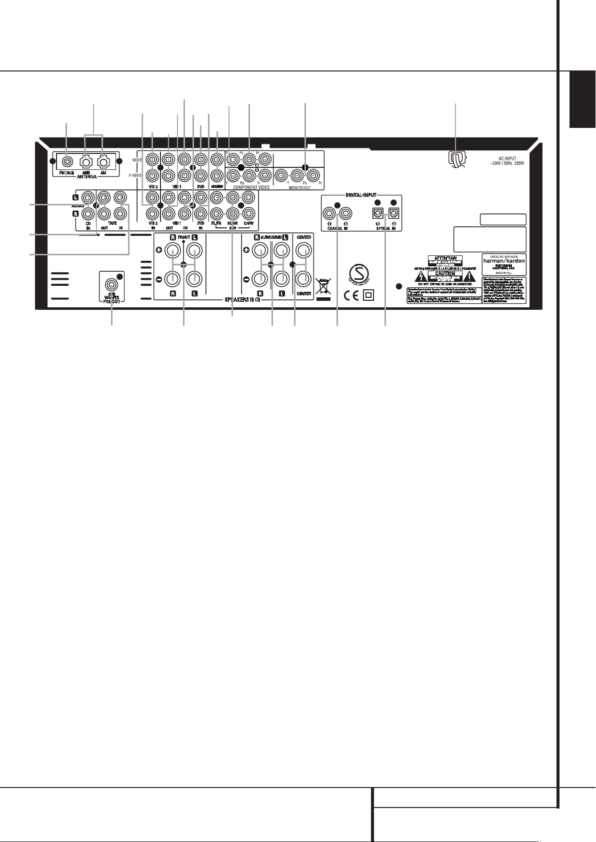
Rear Panel Connections
•
¢
°
¶
c
⁄
B
fi
‚
d
e
¡
™
b
·
‡
fl
›
‹
ª
‹
a
§
£
∞
ENGLISH
0
Tape Inputs
1
Tape Outputs
2
Video 1 Audio Inputs
3
AM Antenna
4
Video 1 Audio Outputs
5
DVD Audio Inputs
6
FM Antenna
7
CD Inputs
8
Video 2 Component Video Inputs
0
Tape Inputs: Connect these jacks to the
PLAY/OUT jacks of an audio recorder.
1
Tape Outputs: Connect these jacks to the
RECORD/INPUT jacks of an audio recorder.
2
Video 1 Audio Inputs: Connect these jacks
to the PLAY/OUT audio jacks on a VCR or other
video source.
3
AM Antenna: Connect theAM loop antenna
supplied with the receiver to these terminals.If an
external AM antenna is used, make connections to
the AM and GND terminals in accordance with
the instructions supplied with the antenna.
9
Coaxial Digital Inputs
A
Subwoofer Output
B
Video Monitor Outputs
C
Front/Center Speaker Outputs
D
Surround Speaker Outputs
E
Component Video Outputs
F
Video 1 Component Video Inputs
G
AC Power Cord
H
DVD Video Inputs
4
Video 1 Audio Outputs: Connect these
jacks to the RECORD/INPUT audio jacks on
a VCR or any other Audio recorder.
5
DVD Audio Inputs: Connect these jacks to
the analog audio jacks on a DVD or other video
source.
6
FM Antenna: Connect the supplied indoor or
an optional external FM antenna to this terminal.
7
CD Inputs: Connect these jacks to the analog output of a compact disc player or CD
changer.
I
Video 1 Video Outputs
J
Video 2 Audio Inputs
K
Video 2 Video Inputs
L
Optical Digital Inputs
M
Video 1 Video Inputs
N
6-Channel Direct Inputs
8
Video 2 Component Video Inputs:
Connect the Y/Pr/Pb component video outputs of
an HDTV Set-top convertor, satellite receiver, or
other video source device with component video
outputs to these jacks.
9
Coaxial Digital Inputs: Connect the coax
digital output from a DVD player, HDTV receiver,
LD player, MD player or CD player to these jacks.
The signal may be either a Dolby Digital signal,
DTS signal or a standard PCM digital source. Do
not connect the RF digital output of an LD player to these jacks.
A
Subwoofer Output: Connect this jack to
the line-level input of a powered subwoofer. If
an external subwoofer amplifier is used, connect
this jack to the subwoofer amplifier input.
REAR PANEL CONNECTIONS 7

Rear Panel Connections
B
Video Monitor Outputs: Connect these
jacks to the composite and/or S-Video input of a
TV monitor or video projector to view the output
of any video source selected by the receiver’s
video switcher.
C
Front/Center Speaker Outputs: Connect
these outputs to the matching + or – terminals
on your front/center speakers.When making
speaker connections, always make certain to
maintain correct polarity by connecting the red
(+) terminals on the AVR to the red (+) terminals
on the speaker and the black (–) terminals on
the AVR to the black (–) terminals on the speakers. (See page 12 for more information on
speaker polarity.)
D
Surround Speaker Outputs: Connect
these outputs to the matching + or – terminals
on your left and right surround speakers.When
making speaker connections always make certain to maintain correct polarity by connecting
the red (+) terminals on the AVR to the red (+)
terminals on the speakers and the black (–) terminals on the AVR to the black (–) terminals on
the speakers. See page 12 for more information
on speaker polarity.
E
Monitor Component Video Outputs:
Connect these outputs to the component video
inputs of a video projector or monitor. When a
source connected to one of the two
Component Video Inputs
the signal will be sent to these jacks.
8F
is selected
F
Video 1 Component Video Inputs:
Connect the Y/Pr/Pb component video outputs of
a DVD player to these jacks.
Note: All component inputs/outputs can be
used for RGB signals too, in the same way as
described for the Y/Pr/Pb signals, then connected
to the jacks with the corresponding color.
RGB connection is not possible if the source outputs a separate sync signal (see page 13).
G
AC Power Cord: Connect the AC plug to an
unswitched AC wall output.
H
DVD Video Inputs: Connect these jacks to
the composite or S-Video output jacks on a DVD
player or other video source.
I
Video 1 Video Outputs: Connect these
jacks to the RECORD/INPUT composite or
S-Video jack on a VCR.
J
Video 2 Audio Inputs: Connect these jacks
to the PLAY/OUT audio jacks on a VCR or other
video source.
K
Video 2 Video Inputs: Connect these jacks
to the PLAY/OUT composite or S-Video jacks on
a second VCR or other video source.
L
Optical Digital Inputs: Connect the optical
digital output from a DVD player, HDTV receiver,
LD player, MD player or CD player to these jacks.
The signal may be either a Dolby Digital signal, a
DTS signal or a standard PCM digital source.
M
Video 1 Video Inputs: Connect these jacks
to the PLAY/OUT composite or S-Video jacks on
a VCR or other video source.
Note: Either the Video or S-Video output of any
S-Video source must be connected to the
AVR, not both in parallel, otherwise the video
may be disturbed or its performance be
adversely effected.
N
6-Channel Direct Inputs: These jacks are
used for connection to source devices such as
DVD-Audio or SACD players with discrete analog
outputs.
8 REAR PANEL CONNECTIONS
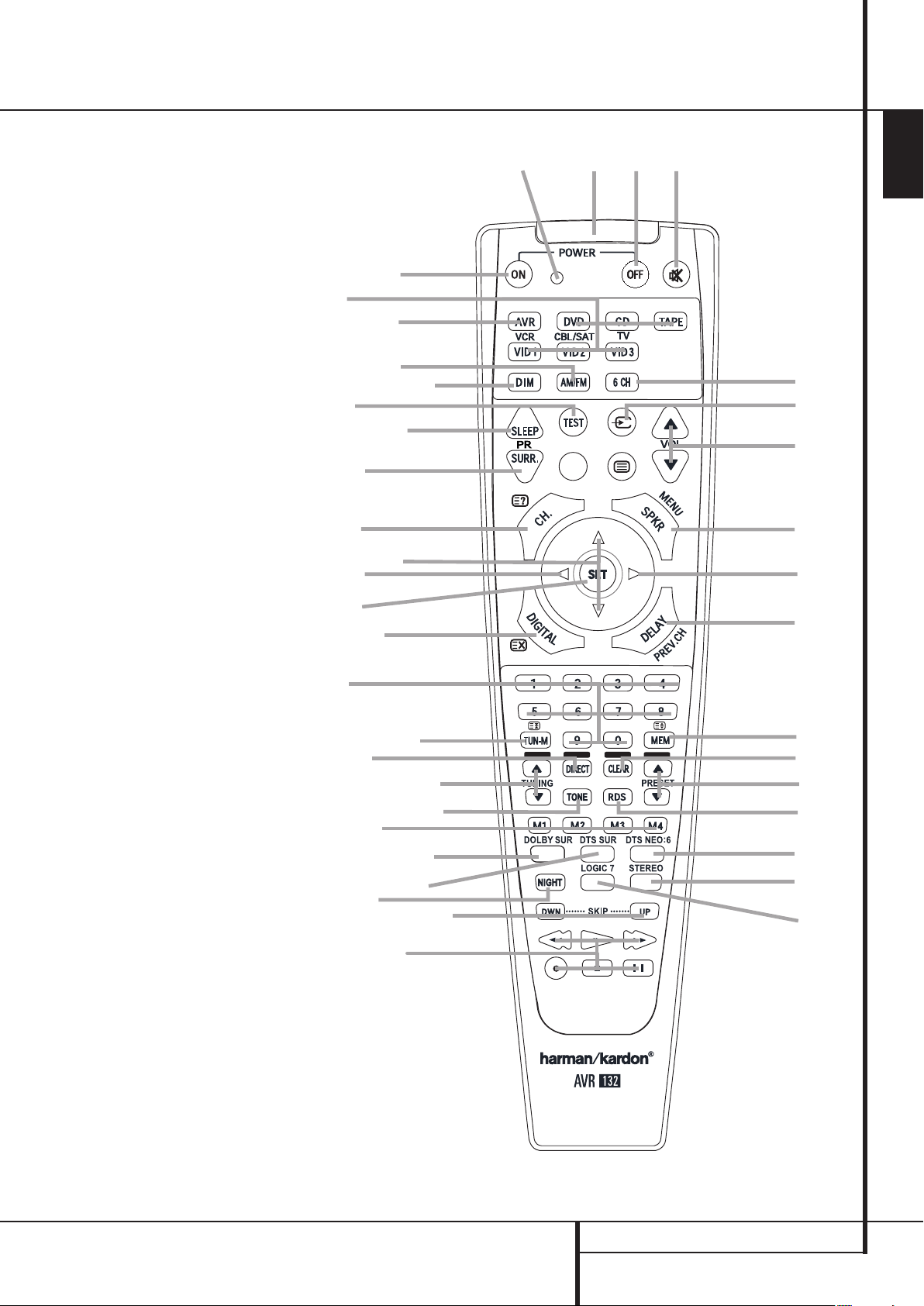
Remote Control Functions
a
e
7
l
q
r
t
`
z
x
y
p
8
g
j
k
m
n
o
s
u
w
v
b
d
c
f
0
Power On Button
1
IR Transmitter Window
2
Program Indicator
3
Power Off Button
4
Input Selectors
5
AVR Selector
6
AM/FM Tuner Select
7
Test Button
8
Sleep Button
9
Surround Mode Selector
A
Night Mode
B
Channel Select Button
K/L
C
D
E
F
G
H
I
J
K
L
M
N
O
P
Q
Buttons
A
Button
Set Button
Digital Select
Numeric Keys
Tuner Mode
Direct Button
Tuning Up/Down
Macro Buttons
Transport Controls
Skip Up/Down Buttons
RDS Select Button
Preset Up/Down
Clear Button
Memory Button
Delay/Prev. Ch.
B
Button
Speaker Select
Tone Mode Button
Volume Up/Down
TV/Video Selector
Mute
Dim Button
Dolby Mode Select Button
DTS Digital Mode Select Button
Logic 7 Mode Select Button
Stereo Mode Select Button
DTS Neo:6 Mode Select Button
6-Channel Direct Input
ENGLISH
NOTE: The function names shown here are each
button’s feature when used with the AVR. Most
buttons have additional functions when used
with other devices. See page 32 and 33 for a list
of these functions.
REMOTE CONTROL FUNCTIONS 9
Remote Control Functions
90
min80min70min60min50min
40
min
30
min20min10min
OFF
IMPORTANT NOTE: The AVR’s remote may be
programmed to control up to seven devices,
including the AVR. Before using the remote, it is
important to remember to press the Input
Selector button
4
that corresponds to the
unit you wish to operate. In addition, the AVR’s
remote is shipped from the factory to operate the
AVR and most Harman Kardon CD or DVD players and cassette decks.The remote is also capable of operating a wide variety of other products
using the control codes that are part of the
remote. Before using the remote with other products, follow the instructions on page 29 to program the proper codes for the products in your
system.
It is also important to remember that many of the
buttons on the remote take on different functions, depending on the product selected using
the Input Selectors.The descriptions shown here
primarily detail the functions of the remote when
it is used to operate the AVR. (See page 32 and
33 for information about alternate functions for
the remote’s buttons.)
0
Power On Button: Press this button to
turn on the power to a device selected by pressing
one of the Input Selectors
1
IR Transmitter Window: Point this window
4
(except Tape).
towards the AVR when pressing buttons on the
remote to make certain that infrared commands
are properly received.
2
Program Indicator: This three-color indicator is used to guide you through the process of
programming the remote. See page 29 for information on programming the remote.
3
Power Off Button: Press this button to
place the AVR or a selected device unit in the
Standby mode.
4
Input Selectors: Pressing one of these
buttons will perform three actions at the same
time. First, if the AVR is not turned on, this will
power up the unit. Next, it will select the source
shown on the button as the input to the AVR.
Finally, it will change the remote control so that
it controls the device selected. After pressing one
of these buttons you must press the
AVR Selector button
5
again to operate the
AVR’s functions with the remote.
5
AVR Selector: Pressing this button will
switch the remote so that it will operate the AVR’s
functions. If the AVR is in the Standby mode, it will
also turn the AVR on.
6
AM/FM Tuner Select: Press this button to
select the AVR’s tuner as the listening choice.
Pressing this button when the tuner is in use will
select between the AM and FM bands.
7
Test Tone: Press this button to begin the
sequence used to calibrate the AVR’s output levels. (See page 19 for more information on
calibrating the AVR.)
8
Sleep Button: Press this button to place
the unit in the Sleep mode.After the time shown
in the display, the AVR will automatically go into
the Standby mode. Each press of the button
changes the time until turn-off in the
following order:
Hold the button pressed for two seconds to turn
off the Sleep mode setting.
Note that this button is also used to change
channels on your TV, VCR and SAT receiver when
selected.
9
Surround Mode Selector: Press this
button to begin the process of changing
the surround mode. After the button has
been pressed, use the
K/L
buttons Cto
select the desired surround mode (See page 21
for more information). Note that this button is
also used to tune channels when the TV, VCR
and SAT receiver is selected using the Input
Selector
A
4
.
Night Mode: Press this button to activate
the Night mode.This mode is available only with
Dolby Digital encoded digital sources, and it preserves dialog (center channel) intelligibilty at low
volume levels (See page 26 for more information).
B
Channel Select Button: This button is
used to start the process of setting the AVR ’s output levels with an external source. Once this button
is pressed, use the
K/L
buttonsCto select the
channel being adjusted, then press the Set button
E
, followed by the
K/L
buttons again, to
change the level setting. (See page 27 for more
information.)
K/L
C
Buttons: These are multi-purpose
buttons. They will be used most frequently to select
a surround mode.These buttons are also used to
increase or decrease output levels when configuring the unit, to select speaker configuration or
to select the digital inputs.They are also used to
enter delay time settings after the Delay button
has been pressed.
When the AVR remote is being programmed for
the codes of another device, these buttons are
also used in the “Auto Search” process (See page
29 for more information on programming the
remote.)
DAButton: This button does not have a
function with the AVR. When a DVD player or TV
is selected, it may be used to navigate the menus
of those devices.
E
Set Button: This button is used to enter
settings into the AVR ’s memory. It is also used in
the setup procedures for delay time, speaker
configuration and channel output level adjustment.
F
Digital Select: Press this button to assign
one of the digital inputs
4G9L
to a
source. (See page 25 for more information on
using digital inputs.)
G
Numeric Keys: These buttons serve as a
ten-button numeric keypad to enter tuner preset
positions.They are also used to select channel
numbers when TV, VCR or Sat receiver has
been selected on the remote, or to select track
numbers on a CD, DVD or LD player, depending
on how the remote has been programmed.
H
Tuner Mode: Press this button when the
tuner is in use to select between automatic
tuning and manual tuning. When the button is
pressed so
Information Display
buttons
MANUAL appears in the Main
F
, pressing the Tuning
J7will move the frequency up or
down in single-step increments.When the FM
band is in use and
Information Display
AUTO appears in the Main
F
, pressing this button
will change to monaural reception making even
week stations audible. (See page 27 for more
information.)
I
Direct Button: Press this button when the
tuner is in use to start the sequence for direct
entry of a station’s frequency. After pressing the
button simply press the proper Numeric Keys
G
to select a station (See page 27 for more
information on the tuner).
J
Tuning Up/Down: When the tuner is in use,
these buttons will tune up or down through the
selected frequency band. If the Tuner Mode but-
ton
H
has been pressed or the Band button
8
on the front panel was held pressed so that
AUTO appears in the Main Information
Display
F
, pressing either of the buttons will
cause the tuner to seek the next station with
acceptable signal strength for quality reception.
When the
Information Display
MANUAL appears in the Main
F
, pressing these buttons will tune stations in single-step increments.
(See page 27 for more information.)
10 REMOTE CONTROL FUNCTIONS
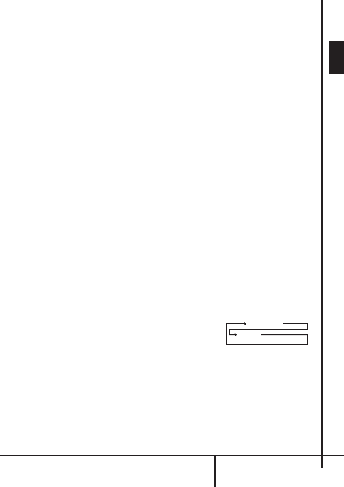
Remote Control Functions
DTS Neo:6 MUSIC
DTS Neo:6
CINEMA
K
Macro Buttons: Press these buttons
to store or recall a “Macro”, which is a
pre-programmed sequence of commands
stored in the remote. (See page 30 for more
information on storing and recalling macros.)
L
Transport Buttons: These buttons do not
have any functions for the AVR, but they may be
programmed for the forward/reverse play operation of a wide variety of CD or DVD players, and
audio or video- cassette recorders. (See page 29
for more information on programming the
remote.)
M
Skip Up/Down Buttons: These buttons
do not have a direct function with the AVR, but
when used with a compatibly programmed CD
or DVD changer they will change the tracks on
the disc currently being played in the changer.
N
RDS Select Button: Press this button to
display the various messages that are part of the
RDS data system of the AVR ’s tuner. (See page
28 for more information on RDS).
O
Preset Up/Down: When the tuner is in
use, press these buttons to scroll through the
stations programmed into the AVR ’s memory.
When CD or DVD is selected using the Input
Selector button
4
, these buttons may func-
tion as Slow Fwd/Rev (DVD) or ”+10” (CD).
P
Clear Button: Press this button to clear
incorrect entries when using the remote to
directly enter a radio station’s frequency.
Q
Memory Button: Press this button to enter
a radio station into the AVR ’s preset memory.Two
underline indicators will flash at the right side of
the Main Information Display
F
, you then
have five seconds to enter a preset memory
location using the Numeric Keys
G
. (See
page 27 for more information.)
Delay/Prev Ch.: Press this button to begin
the process for setting the delay times used by
the AVR when processing surround sound. After
pressing this button, the delay times are entered
by pressing the Set button
K/L
the
buttons Cto change the setting.
E
and then using
Press the Set button again to complete the
process. (See page 19 for more information.)
BButton: This button does not have a
function with the AVR. When a DVD player or TV
is selected, it may be used to navigate the menus
of those devices.
Speaker Select: Press this button to
begin the process of configuring the AVR’s Bass
Management System for use with the type of
speakers used in your system. Once the button
has been pressed, use the
K/L
buttons Cto
select the channel you wish to set up. Press the
Set button
E
and then select the speaker
type (see page 16 for more information.)
Tone Mode: Pressing this button enables
or disables the Balance, Bass and Treble tone
controls.When the button is pressed so that the
words
TONE I N appear in the Main
Information Display
F
, the settings of the
Bass and Treble controls and of the Balance
control will affect the output signals.When the
button is pressed so that the words
OUT
appear in the Main Information
Display
F
, the output signal will be “flat,”
TONE
without any balance, bass or treble alteration.
Volume Up/Down: Press these buttons to
raise or lower the system volume.
TV/Video Button: This button does not
have a direct function on the AVR, but when
used with a compatibly programmed VCR, DVD
or satellite receiver that has a “TV/Video” function, pressing this button will switch between
the output of the player or receiver and the
external video input to that player. Consult the
Owner’s Manual for your specific player or
receiver for the details of how it implements this
function.
Mute: Press this button to momentarily
silence the AVR or TV set being controlled,
depending on which device has been selected.
When the AVR remote is being programmed to
operate another device, this button is pressed
with the Input Selector button
4
to begin
the programming process. (See page 29 for more
information on programming the remote.)
NOTE: As any of the remote buttons pressed is
active with the device selected, the corresponding Selector button
45
will briefly flash
red to confirm your selection.
Dim Button: Press this button to activate
the Dimmer function, which reduces the brightness of the front panel display, or turn it off
entirely.The first press of the button shows the
default state, which is full brightness by indicating
VFD FULL in the Main Information
Display
F
. Press the button again within five
seconds to reduce the brightness by 50%, as
indicated by
VFD HALF. Press the button
again within five seconds and the main display
will go completely dark. Note that this setting is
temporary; the display will always return to full
brightness when the AVR is turned on. In addition,both the Power Indicator
2
and the blue
accent lighting inside the volume control will
always remain at full brightness regardless of
the setting. This is to remind you that the AVR is
still turned on.
Dolby Mode Selector: This button is used
to select one of the available Dolby Surround
processing modes. Each press of this button will
select one of the Dolby Pro Logic II modes, Dolby
3 Stereo or Dolby Digital. Note that the Dolby
Digital mode is only available with a digital input
selected and the other modes only as long as a
Dolby Digital source is not playing. See page 22
for the available Dolby surround mode options.
DTS Digital Mode Selector: When a DTS
source is in use the AVR will select the appropriate mode automatically and no other mode will
be available. Pressing this button will display the
mode currently selected by the AVR´s decoder,
depending on the surround material played and
the speaker setting.
Logic 7 Selector: Press this button to
select one of the available Logic 7 surround
modes. (See page 22 for the available Logic 7
options).
Stereo Mode Selector: Press this button to
select a stereo playback mode.When the button
is pressed so that
in the Main Information Display
DSP SURR OFF appears
F
, the AVR
will operate in a bypass mode with true fully
analog, two-channel left/right stereo mode with
no surround processing or bass management as
opposed to other modes where digital processing is used. When the button is pressed so that
SURROUND OFF appears in the Main
Information Display
F
, you may enjoy a
two-channel presentation of the sound along
with the benefits of bass management. When
the button is pressed so that
5 C H STEREO
appears, the stereo signal is routed to all five
speakers, if installed.(See page 18 for more
information on stereo playback modes).
DTS Neo:6 Mode Selector: Pressing this
selector button cycles the AVR through the
various DTS Neo:6 modes, which extract a fivechannel surround field from two-channel program material (from PCM source or analog input
signal). The first press selects the last DTS Neo:6
surround mode that was in use, and each
subsequent press selects the next mode in the
following order:
6-Channel Direct Input: Press this button
to select the component connected to the
6-Channel Direct Input
N
as the audio.
Note that when you wish to use the Six Channel
Direct Input in conjunction with a video source,
you must first select the video source by pressing
one of the Input Selectors
4
. Then press this
button to choose the 6-Channel Direct Input
N
as the audio source.
ENGLISH
REMOTE CONTROL FUNCTIONS 11
 Loading...