

Page 1
Page 2

This user manual describes all proceedings concerning the
operations of this CNC system in detail as much as possible. However, it is
impractical to give particular descriptions for all unnecessary or unallowable
system operations due to the manual text limit, product specific applications
and other causes. Therefore, the proceedings not indicated herein should
be considered impractical or unallowable.
This user manual is the property of GSK CNC Equipment Co., Ltd. All
rights are reserved. It is against the law for any organization or individual
to publish or reprint this manual without the express written permission of
GSK and the latter reserves the right to ascertain their legal liability.
- -
I
Page 3

Installation and Connection Manual of GSK218MC CNC System
Preface
Your Excellency,
It’s our pleasure for your patronage and purchase of this
GSK218MC Series Machining Center CNC System made by GSK CNC
Equipment Co., Ltd.
This manual is the part of the “Installation and Connection”, which
is introduced the installation and connection and the PLC
programming method of the machining center CNC of the
GSK218MC.
In order to guarantee the product is operated with a safe, normal and
effective situation, it is necessary to carefully read this manual before installing
and using this product.
Chinese version of all technical documents in Chinese and English
languages is regarded as final.
II
Page 4

Preface and Precaution
Security Precaution
Accident may occur by improper connection and operation !This
system only can be operated by authorized and qualified personnel.
Please carefully read this manual before using!
Especially prompt: The power installed on/inside the main cabinet
is a special one offering by our company CNC system.
Never attempt to use for other purposes by this power.
Otherwise, huge hazard may occur.
III
Page 5

Installation and Connection Manual of GSK218MC CNC System
Warning, Notice and Explanation
Statement!
z In this manual we have tried as much as possible to describe all
various matters. However, we cannot describe all the matters which
must not be done, or which cannot be done, because there are so
many possibilities. Therefore, matters which are not especially
described as possible in this manual should be regarded as
“impossible”.
Warning!
z Before installing, programming and operating the machine, thoroughly
read this manual and user manual issued by the machine
manufacturer, and rigidly operate the machine based upon the
requirement of this manual, otherwise, possibly causing damage to
the workpiece and/or machine itself, or injury to the user.
z The product functions and technical indexes (such as accuracy,
velocity) described in this manual are only for this machine, which
installs the CNC system of this product. The actual function
configuration and technical capacity are determined by the machine
manufacturer, and the function configurations of the CNC machine
and technical indexes are subjected on the manual issued by the
machine builder.
All specifications and designs are subject to change without notice.
Notice!
IV
Page 6

Preface and Precaution
Safety Precautions
■ Transportation and Storage
z Do not pile up the carton over 6 layers.
z Do not climb, stand on the carton, and as well not place the heave objects on it.
z Do not drag or move the product using the cables connected with the product.
z Do not crash or scratch the panel and display screen.
z Avoid damp, sunshine and raining on the product carton.
■ Open carton to inspect
z Ensure that it is your purchased product after opening the carton.
z Check whether the product is damaged during transporting.
z Confirm whether each part is prepared or damaged based upon the packing list.
z Contact our company immediately if the product type is inconsistent with the
packing list, lack of accessories or damage in transportation.
■ Wiring
z The person who attends the wiring and check should have the corresponding
professional capacity.
z The product should be reliably grounded, and its resistance should be less than
0.1Ω and can not be used the neutral conductor (zero cable) to replace the
ground wire.
z The wiring should be correct and firm, otherwise, possibly causing the
malfunction in product or unexpectable result.
z The surge absorb diode connected with the product should be linked based upon
the described direction, otherwise, it may damage the product.
z Before Inserting/pulling out the plug or opening the main cabinet of the product, it
is important to cut off the product’s power.
■ Inspection and maintenance
z Cut off the power before inspecting and maintaining or changing the
components.
z Check the malfunction when the short-circuit or overloading occurs. The
computer can be started after the malfunction is eliminated.
z Do not power ON/OFF frequently for the product, if you want to turn on the
power again after power off, its interval time is 1min. at least.
V
Page 7

Installation and Connection Manual of GSK218MC CNC System
Volume Ⅰ Programming Description
Introduce the technical specification, product type series and parameter
configuration, command code and program format of 218MC series machining center
CNC system.
Volume Ⅱ Function Description
Introduce the main function of the GSK218MC series machining center CNC
system.
Volume Ⅲ Operation Description
Introduce the operations of the GSK218MC series machining center CNC
system
Volume Ⅳ Installation and Connection
Introduce the installation, connection and setting methods of the GSK218MC
series machining center CNC system.
Appendix
Introduce the use explanations of the GSK218MC series machining center CNC
system and the appendix
VI
Page 8

Preface and Precaution
Security Responsibility
Security responsibility of the manufacturer
——Manufacturer should take responsibility for the design and structure danger of the
motor and the accessories which have been eliminated and/or controlled.
——Manufacturer should take responsibility for the security of the motor and
accessories.
——Manufacturer should take responsibility for the offered information and
suggestions for the user.
Security responsibility of the users
——User should know and understand about the contents of security operations by
learning and training the security operations of the motor.
——User should take responsibility for the security and danger because of increasing,
changing or modifying the original motor or accessory by themselves.
——User should take responsibility for the danger without following the operations,
maintenances, installations and storages described in the manual.
This manual is stored by the last user.
Sincerely thanks for your friendly supporting of GSK’s
products!
VII
Page 9

Installation and Connection Manual of GSK218MC CNC System
VIII
Page 10

Contents
CONTENTS
VOlUME Ⅰ PROGRAMMING......................................................................................0H1
CHAPTER ONE THE COMPILATION SCHEDULE OF SEQUENCE PROGRAMMING ...........
1.1 GSK218MC Series PLC Specification .....................................................................................
1.2 The Concept of the Sequence Programming ......................................................................... 3H3
1.3 Distribution Interface (Step one) ...............................................................................................
1.4 Ladder Diagram Programming (Step two)............................................................................... 5H4
1.5 Sequence Programming Debugging (Step 3)......................................................................... 6H4
CHAPTER TWO SEQUENCE PROGRAMMING.......................................................................
2.1 Performance Process of Sequence Programming ................................................................
2.2 The Performance of the Cycle ..................................................................................................
2.3 The Priority Sequence of the Performance (the 1st Level, the 2nd level).......................... 10H6
2.4 Sequence Programming Structure ...........................................................................................
2.5 The Treatment of the Input/output Signal ................................................................................ 12H8
2.6 Interlocking.................................................................................................................................
CHAPTER THREE PLC ADDRESS.........................................................................................
3.1 Machine → PLC address (X)..................................................................................................
3.2 PLC → Address of the Machine Tool Side (Y) .................................................................
3.3 PLC →CNC Address (G) ........................................................................................................
3.4 CNC →PLC Address (F) .........................................................................................................
3.5 Internal Replay Address (R) ....................................................................................................
3.6 Nonvolatile Relay Address (K) ................................................................................................
3.7 Information Display Request Address (A) ............................................................................. 21H16
3.8 Counter Timer (C) ..................................................................................................................... 22H17
3.9 Counter Preset Value Address (DC) ......................................................................................
3.10 Timer Address (T) ................................................................................................................... 24H17
3.11 Presetting Value Address of the Timer (DT)........................................................................
3.12 Data Table Address (D) ..........................................................................................................
3.13 Sign Address (L)......................................................................................................................
3.14 Subprogram Number (P) .......................................................................................................
CHAPTER FOUR PLC BASIS CODE......................................................................................
4.1 RD, RD.NOT, WRT, and WRT.NOT Codes...........................................................................
4.2 AND, AND.NOT Codes............................................................................................................. 31H19
4.3 OR, OR.NOT Codes.................................................................................................................
4.4 OR. STK Code........................................................................................................................... 33H20
4.5 AND. STK Code ........................................................................................................................ 34H20
CHAPTER FIVE PLC FUNCTION CODE ................................................................................
st
5.1 END1 (End of the 1
5.2 END2 (The End of the 2
Level Sequence Program) ................................................................. 36H22
nd
Sequence Program) ................................................................... 37H23
5.3 CALL (Call Subprogram)..........................................................................................................
5.4 CALLU (Call Subprogram Without Condition) ......................................................................
5.5 SP (Subprogram) ......................................................................................................................
5.6 SPE (End of Subprogram).......................................................................................................
1H3
2H3
4H4
7H5
8H5
9H6
11H7
13H10
14H11
15H11
16H13
17H14
18H15
19H15
20H16
23H17
25H17
26H17
27H17
28H17
29H18
30H18
32H19
35H22
38H23
39H23
40H24
41H24
IX
Page 11

Installation and Connection Manual of GSK218MC CNC System
5.7 SET (Replacement/Setting) .....................................................................................................42H25
5.8 RST (Resetting) .........................................................................................................................43H25
5.9 JMPB (Mark Number Skip) ......................................................................................................44H26
5.10 LBL (Mark Number).................................................................................................................
45H26
5.11 TMR (Timer) .............................................................................................................................46H27
5.12 TMRB (Fixed Timer)................................................................................................................47H28
5.13 TMRC (TIMER)........................................................................................................................
48H28
5.14 CRT (Binary Counter).............................................................................................................49H29
5.15 DEC (Binary Decoding) ..........................................................................................................50H30
5.16 COD (Binary System Code Conversion) .............................................................................51H31
5.17 COM (Concentric Line Control).............................................................................................
52H33
5.18 COME (Concentric Line Control End)..................................................................................53H33
5.19 ROT (Binary Rotation Control) ..............................................................................................54H33
5.20 SFT (Register Displacement/Shifting)..................................................................................
55H35
5.21 DIFU (Rising Edge Detection)...............................................................................................56H36
5.22 DIFD (Descending Edge Detection) .....................................................................................57H37
5.23 COMP (The Comparison of the Binary Number)................................................................
58H38
5.24 COIN (Consistency Comparison) ......................................................................................... 59H38
5.25 MOVN (Data Transmission)...................................................................................................60H39
5.26 MOVB (Transmission of 1 Byte)............................................................................................
61H40
5.27 MOVW (Transmission of Two Bytes) ...................................................................................62H40
5.28 XMOV (Binary Indexed Data Transmission) .......................................................................63H41
5.29 DSCH (Binary Data Index).....................................................................................................
64H42
5.30 ADD (Binary Addition).............................................................................................................65H43
5.31 SUB (Binary Subtraction).......................................................................................................66H44
5.32 ANDF (Bit-by-bit AND)............................................................................................................67H45
5.34 NOT (Bit-by-bit NOT)..............................................................................................................
68H47
5.35 EOR (Exclusive OR) ...............................................................................................................69H47
CHAPTER SIX THE COMPILATION LIMIT OF THE LADDER DIAGRAM ..............................
70H49
VOLUME II FUNCTION EXPLANATION.................................................................... 71H51
CHAPTER ONE CONTROLLABLE AXIS ................................................................................
1.1 The output of the axis movement............................................................................................
1.2 Servo Ready Signal ..................................................................................................................
CHAPTER TWO READY FOR OPERATION...........................................................................
2.1 ESP..............................................................................................................................................
2.2 CNC Overtravel Signal .............................................................................................................
2.3 Alarm Signal ...............................................................................................................................
2.4 Selection of the Operation Method .........................................................................................79H56
2.5 State Output Signal ................................................................................................................80H57
CHAPTER THREE MANUAL OPERATION.............................................................................
3.1 JOG Feed/Incremental Feed ...................................................................................................
3.2 MPG (Manual Pulse Generator) / Single Step Feed............................................................
CHAPTER FOUR REFERENCE POSITION RETURN ...........................................................
4.1 Manual Reference Position Return.........................................................................................
4.2 Return to the Reference Position Detection Signal..............................................................
4.3 Area Detection Signal ...............................................................................................................87H62
X
72H53
73H53
74H54
75H55
76H55
77H55
78H56
81H58
82H58
83H59
84H60
85H60
86H61
Page 12

Contents
CHAPTER FIVE AUTOMATICAL OPERATION .......................................................................88H64
5.1 Cycle Start/ Feed Hold .............................................................................................................
5.2 Reset...........................................................................................................................................
5.3 Program test .............................................................................................................................. 91H66
5.4 Skip Optional Block................................................................................................................... 92H68
CHAPTER SIX FEEDRATE CONTROL...................................................................................
6.1 Rapid Traverse Rate.................................................................................................................
6.2 Feedrate Override..................................................................................................................... 95H71
6.3 Override Cancellation...............................................................................................................
CHAPTER SEVEN MISCELLANEOUS FUNCTION................................................................
7.1 M Code Miscellaneous Function.............................................................................................
7.2 S Code Miscellaneous Function .............................................................................................
7.3 T Code Miscellaneous Function.............................................................................................. 100H74
7.4 Miscellaneous Function Lock .................................................................................................. 101H76
CHAPTER EIGHT SPINDLE SPEED FUNCTION...................................................................
8.1 Spindle Speed Control Method ...............................................................................................
8.2 Rigid Tapping .............................................................................................................................
CHAPTER NINE PROGRAMMING CODE ..............................................................................
9.1 User Macro Program ................................................................................................................
9.2 Canned Cycle ............................................................................................................................
CHAPTER TEN DISPLAY/SETTING .......................................................................................
10.1 Clock Function.........................................................................................................................
10.2 Display the Operation Record............................................................................................... 110H85
10.3 Help Function .......................................................................................................................... 111H85
CHAPTER ELEVEN MEASURING ..........................................................................................
11.1 Skip Function ...........................................................................................................................
CHAPTER TWELVE PANEL LOCK SETTING.........................................................................
89H64
90H65
93H70
94H70
96H71
97H72
98H72
99H72
102H78
103H78
104H80
105H81
106H81
107H83
108H85
109H85
112H86
113H86
114H87
VOLUME III OPERATION EXPLANATION.................................................................115H93
CHAPTER ONE PLC INTERFACE DISPLAY ..........................................................................
1.1 GSK218MC The Automatic Operation in PLC ON............................................................
1.2 Programmable Interface Display ............................................................................................ 118H95
CHAPTER TWO PLC PROGRAMMING OPERATION ..........................................................
2.2 Basis Code...............................................................................................................................
2.3 The Operation Explanation of the Ladder Diagram ...........................................................
2.4 Function Code .........................................................................................................................
2.5 Command Table ...................................................................................................................... 123H108
2.6 Compilation Command........................................................................................................... 124H109
2.7 PLC Operation Steps..............................................................................................................
CHAPTER THREE PLC ADDRESS AND PARAMETER SETTING.......................................
3.1 Nonvolatile/Hold Relay............................................................................................................
3.2 Timer ............................................................................................................................... ...........128H112
3.3 Data List ....................................................................................................................................129H113
3.4 Counter ......................................................................................................................................130H114
3.5 M function corresponding to the F address..........................................................................
CHAPTER FOUR THE USER EXPLANATION OF THE LADDER DIAGRAM SOFTWARE
EDIT .........................................................................................................................................
116H95
117H95
119H103
120H104
121H105
122H107
125H109
126H111
127H111
131H115
132H117
XI
Page 13

Installation and Connection Manual of GSK218MC CNC System
4.1 Brief ............................................................................................................................... ............ 133H117
4.2 Software Introduction.............................................................................................................. 134H117
4.3 Software Operation ................................................................................................................. 135H119
VOLUME Ⅳ INSTALLATION AND CONNCETION................................................. 136H127
CHAPTER ONE THE SYSTEM CONFIGURATION AND INSTALLATION.............. 137H129
1.1 Composition of the System ................................................................................................
1.2 The System Installation and Connection ............................................................................139H129
1.3 CNC System Installation Dimension Figure .......................................................................
1.4 The Additional Panel Figure ...............................................................................................
138H129
140H131
141H136
CHAPTER TWO CONNECTION BETWEEN EQUIPMENTS .................................. 142H137
2.1 Connection Diagram of the External System......................................................................143H137
2.1.1 The Layout of Interface Position ........................................................................................
2.1.2 The Connection Diagram ....................................................................................................
2.2 Connection between the System and the Drive Unit ..........................................................
2.2.1 The System Interface Figure ..............................................................................................
2.2.2 The Interface Signal List .....................................................................................................148H140
2.2.3 Introduction of Signals.........................................................................................................149H140
2.2.4 The Cable Connection Diagram.........................................................................................
2.3 RS232 Standard Series Interfaces .....................................................................................
2.4 Connection between MPG and Handhold Unit...................................................................
2.4.1 Interface Signal Diagram ....................................................................................................
2.4.2 Introduction of Interface Signals ........................................................................................154H145
2.5 Connection of the Spindle Units .........................................................................................
2.5.1 List of the Interface Signals ................................................................................................
2.5.3 The Connection Circuit of DAP03 Interfaces ................................................................... 157H148
2.6 The System Power Supply Interface ..................................................................................
2.7 The Control Interface of the External Power Supply...........................................................
144H137
145H138
146H139
147H139
150H142
151H144
152H144
153H144
155H147
156H147
158H149
159H149
CHAPTER THREE THE MACHINE CONTROL I/O INTERFACE ............................ 160H150
3.1 The Interface Signal List.....................................................................................................
3.2 The Input Interfaces ...........................................................................................................
3.2.1 The Circuit Principle of the Input Interface .......................................................................
3.2.2 The Interface Definition of the Input Signals....................................................................
3.3 The Output Interface ..........................................................................................................
3.3.1 The Circuit Principle of the Output Interface....................................................................
3.3.2 The Definitions of the Output Signal Interfaces...............................................................167H155
161H150
162H151
163H151
164H152
165H154
166H154
CHAPTER FOUR MACHINE DEBUGGING............................................................. 168H157
4.1 Debugging Ready...............................................................................................................
4.2 System Power-on ...............................................................................................................
4.3 Emergency Stop and Limit .................................................................................................
4.4 Changing the Gear Ratio....................................................................................................
4.5 Backlash Compensation.....................................................................................................173H162
4.6 Setting the Drive Unit .........................................................................................................
XII
169H157
170H158
171H158
172H161
174H164
Page 14

Contents
4.7 The Machine Screw Pitch Compensation...........................................................................175H165
4.8 Mechanical Zero Return (Machine Zero Return) ................................................................
176H167
4.9 Controlling the Input and Output Signals during the Spindle CW and CCW Rotation.........177H171
4.10 The Spindle Automatic Gear Change Control ...................................................................
178H172
4.11 The External Cycle Start and Feed Hold...........................................................................179H173
4.12 The External Editing Lock and the External Operation Panel Lock ..................................
180H174
4.13 Cooling, Lubricating and Chip Removal Control...............................................................181H175
4.14 Setting the Relative Feedrate ...........................................................................................
182H176
4.15 Setting the Relative Tapping Parameters .........................................................................183H178
APPENDIX ..................................................................................................................184H181
APPENDIX ONE THE USAGE GUIDE OF THE LADDER DIAGRAM OF GSK218MC
WITH THE TURRET MAGAZINE ................................................................................
185H183
1. Points for Attention during Using the Ladder Diagram when GSK218MC with the Turret
Magazine..................................................................................................................................186H183
2. The Allocation and Definitions of I/O Address and Internal Software Components in CNC PLC
of GSK218MC ..........................................................................................................................
3. Usage and Maintenance of GSK218MC CNC System with the Turret Magazine......................
187H183
188H212
APPENDIX TWO THE USAGE GUIDE OF LADDER DIAGRAM OF GSK218MC WITH
THE DISC MAGAZINE ................................................................................................189H221
1. Points for Attention of Using the Disc Magazine: ..................................................................190H221
2. The Allocation and Definition of PMC, I/O Address and the Internal Software Components in
GSK218MC CNC System.........................................................................................................
3. Usage and Maintenance of GSK218MC CNC SYSTEM with the Disc Magazine ................
191H222
192H254
4. Note of GSK218MC CNC System with the Disc Magazine Macro Program.........................193H262
APPENDIX THREE THE ALLOCATED FILE FORMAT OF THE LADDER DIAGRAM
....................................................................................................................................194H263
1. M Code M00—Meaning of F Signal in M99..........................................................................
2. “%” in a Single Line Meaning Saving M Code Information End ............................................196H263
3. X signal X0.0---The Code and Meaning of X6.7 ...................................................................
4. Y Signal Y0.0—The Code and Meaning of Y5.7...................................................................198H263
5. K signal K6.0---The Code and Meaning of K63.7 .................................................................
6. A signal A0.0---The Code and Meaning of A31.7..................................................................200H264
7. End// End Symbol.................................................................................................................201H264
195H263
197H263
199H264
XIII
Page 15

Installation and Connection Manual of GSK218MC CNC System
XIV
Page 16

Chapter One The Compilation Schedule of the Sequence Programming
Volume I Programming
VOlUME Ⅰ PROGRAMMING
1
Page 17

Installation and Connection Manual of GSK218MC CNC System
Volume I Programming
VolumI Programming
2
Page 18

Chapter One The Compilation Schedule of the Sequence Programming
CHAPTER ONE THE COMPILATION SCHEDULE OF SEQUENCE
PROGRAMMING
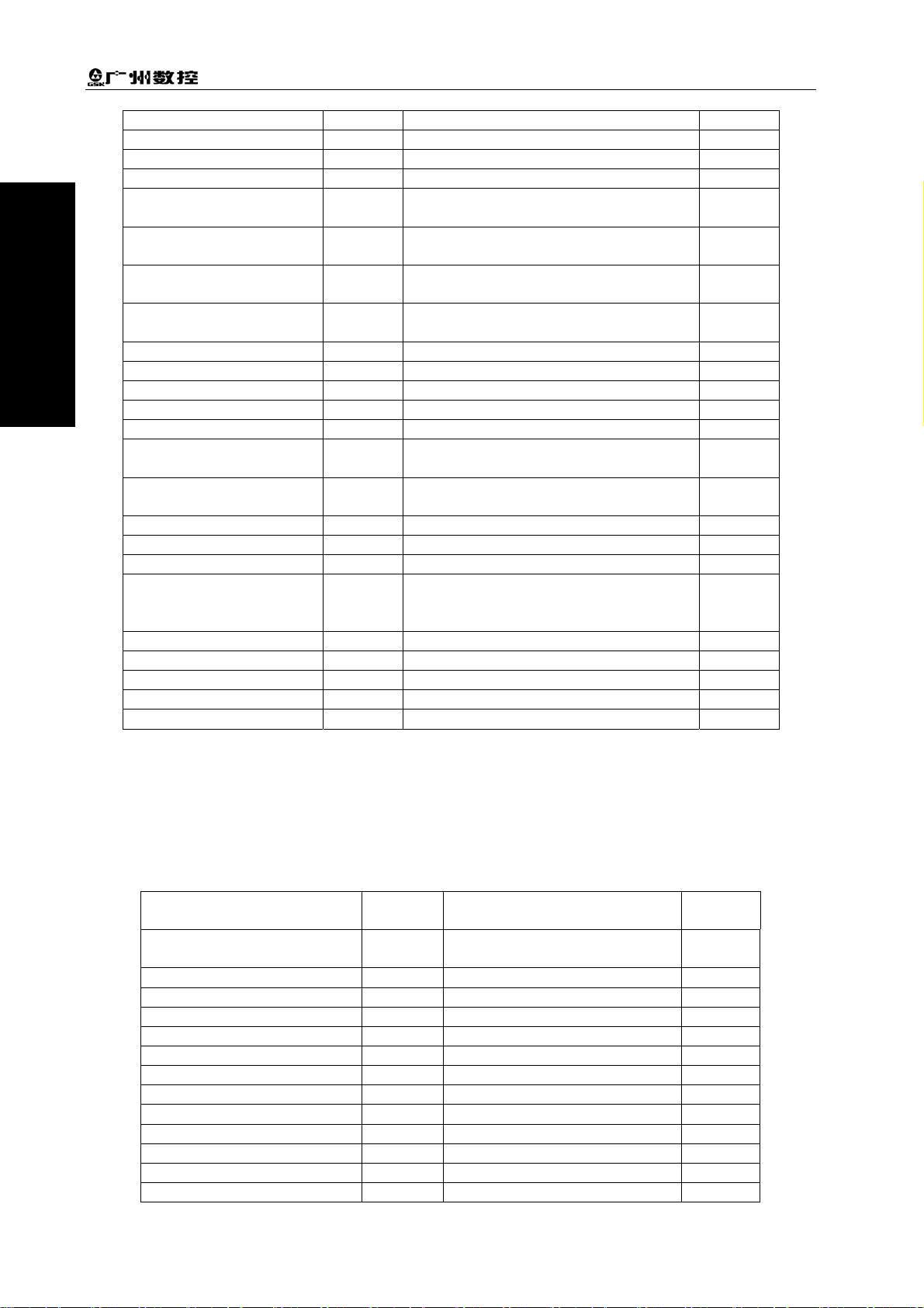
1.1 GSK218MC Series PLC Specification
GSK218MC series PLC specification is shown below:
Table 1-1-1
Specification GSK218MC Series PLC
Programming language Ladder
Program level 2
The 1st level program execution cycle 8ms
Basis code average treatment time 5μs
Programming capacity 4700 steps
Code Basis code + function code
Internal relay (R)
PLC alarm detection (A)
Nonvolatile memory area
Timer (T)
Counter (C)
Data base (D)
Nonvolatile relay (K)
Counter prevalue data register (DC)
Timer prevalue data register (DT)
Subprogram (P)
Mark (L)
Input signal of NC side (F)
Signal outputs to the NC side (G)
Volume I Programming
0~511 (byte)
0~31 (byte)
0~127 (word)
0~127 (word)
0~255 (word)
0~63 (byte)
0~127 (word)
0~127 (word)
0~99
0~99
0~63 (byte)
0~63 (byte)
I/O module (X)
(Y)
0~63 (byte)
0~47 (byte)
1.2 The Concept of the Sequence Programming
The programming is performed a logic control to the machine tool and its relative equipments, which
is called sequence programming.
After the programming is converted into some kind of format, CPU can be performed the code and
calculation treatment for it, and its fruits can be memorized to RAM. CPU can be rapidly read each
code stored in the memory, which can be performed the programming according to the calculation
operation.
The compiling of the sequence programming starts with developing of the ladder diagram
3
Page 19

Installation and Connection Manual of GSK218MC CNC System
1.3 Distribution Interface (Step one)
The interface can be distributed after confirming the controlled object and calculating the points of the
Volume I Programming
corresponding input/output signal.
Refer to the Chapter Four Input/output interface signal table in the part of the Installation and
Connection when distributing the interface.
VolumI Programming
1.4 Ladder Diagram Programming (Step two)
The control operation required by the machine tool can be expressed by the ladder diagram with the
on-line compiling of the GSK218MC. The functions, such as the timer and counter, can not be
expressed by relay symbols, which can be indicated by the specified function code symbols.
The compiled ladder diagram should be stored and converted into the corresponding PLC codes
before operating, namely, the so-called instruction list.
1.5 Sequence Programming Debugging (Step 3)
The sequence programming can be debugged using the following methods:
1) Debugging with emulator
The machine tool can be replaced by an emulator (it composes of the lights and switches). The
input signal state of the machine tool can be expressed by the ON or OFF of the switches; and
the output signal state can be indicated by the ON or OFF of the light.
2) Debugging with actual operation
Debug on the actual machine tool. It is better to prepare the precautions before debugging, due
to an unexpected behavior may occur.
4
Page 20
Chapter Two Sequence Programming
CHAPTER TWO SEQUENCE PROGRAMMING
The operating principle is different with the common relay, because the PLC sequence controlling is
carried out by compiling the on-line diagram. And therefore, it is better to thoroughly understand the
sequence controlling principle when designing the PLC sequence programming.
2.1 Performance Process of Sequence Programming
In the general relay controlling circuits, each of them can be simultaneously operated. When the relay
A is operated in the following figure, the replay D and E can be operated (when the contactor A and B
are closed) at the same. Each replay in the PLC sequence control is operated in turn. The relay D is
operated before relay A, and then the relay E operates (refer to the following figure). Namely, each
relay is operated based upon the sequence of the ladder diagram (compiling sequence).
A
A
Fig. 2.1 (a) Circuit illustration
B
D
C
E
Volume I Programming
The differences between the relay circuit and PLC programming operation are shown below in the Fig.
2.1 (b) and Fig. 2.1 (c).
A
A
C
B
C
Fig. 2.1 (b)
A
C
A
C
B
Fig. 2.1 (c)
(1) Relay circuit
Both Fig. 2.1 (b) and Fig. 2.1 (c) are shared a same operation. B and C are switched on after A is
turned on. B is cut off after C is ON.
5
Page 21
Installation and Connection Manual of GSK218MC CNC System
(2) PLC program
A same relay is shared a same circuit, refer to the Fig. 2.1 (b); B and C are switched on after A is
turned on. B is cut off after one cycle of the PLC program is performed. In the Fig. 2.1 (c), C is ON
instead of B, after C is turned on.
Volume I Programming
2.2 The Performance of the Cycle
VolumI Programming
PLC performs from the beginning to the end of the ladder diagram. It performs again from the
beginning of the ladder diagram after this diagram is performed, which is called cycle performance.
The performance time from the beginning to the end of the ladder diagram is abbreviated as a period
of a cycle treatment. The shorter of the treatment period is, the stronger of the response capacity of
the signal is.
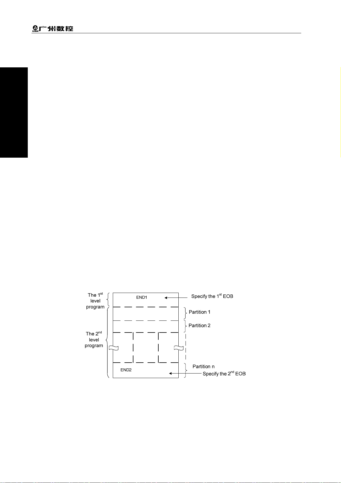
2.3 The Priority Sequence of the Performance (the 1st Level, the 2nd
level)
GSK218MC PLC program are composed of two parts: the 1st level program and the 2nd level program,
which are inconsistent with the performance period.
st
The 1
level program performs once each 8ms, which can be treated some fast corresponding and
short pulse.
nd
The 2
may divide the 2
program performs once each 8*nms. N is the partition value of the 2nd level program. PLC
nd
level program into N parts when the 2nd level program is executed. It is performed
one part for each 8ms.
Fig. 2-3-1
PLC in the GSK218MC is separately performed in the PLC-AVR SCM. The 1ms of each 8ms is the
communication time for reading the PLC data from the CNC. The 5ms is that the PLC gains the
system control signal (F. X), and uploads the control result data (G, Y parameter) external port I/O.
PLC is always performed the ladder diagram calculation other than the interruption of the response
exchange data.
6
Page 22
Chapter Two Sequence Programming
Fig. 2-3-2
nd
When the last partition value of the 2
executed from the beginning of the program. In this case, when the partition value is n, the
performance time of one cycle is 8*n ms. The 1
program performs once each 8*n ms. If its steps of the 1
the steps of the 2
nd
level program within 8ms should be reduced correspondingly; the partition value
may be increased, and the treatment time of the overall program will be longer. So, the compiling of
st
level program should be shorter.
the 1
level program of the n is performed, the program is then
st
level program performs once each 8ms; the 2nd level
st
level program is increased, and therefore
Volume I Programming
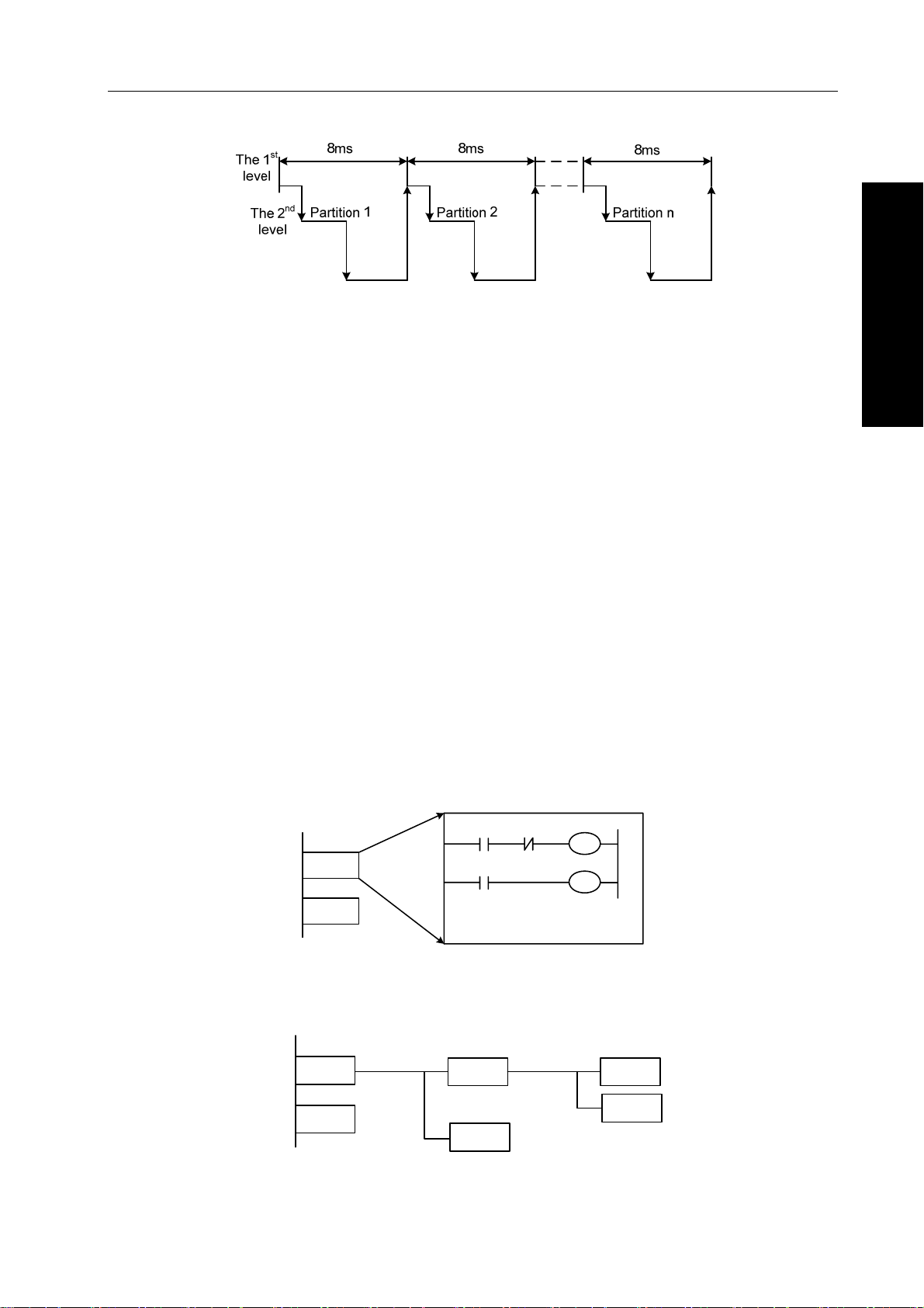
2.4 Sequence Programming Structure
The ladder diagram is compiled with sequence in the traditional PLC. It owns the following
advantages in the ladder diagram language allowing the structured programming:
1. The program is easy to comprehend and compile.
2. It is more convenient to find the faults during the programming.
3. It is easy to find some reasons when the operation malfunction occurs.
The methods of the main structure programming are shown below:
1) Sub-program
The subprogram is regarded as a treatment unit based on the ladder diagram.
C
A
Task A
Task B
A
.
.
.
.
Fig. 2-4-1
2) Nesting
One subprogram can be performed the task by calling another one.
B
C
Main program
Task A
Task B
Subprogram 1 Subprogram 2
Task A1
Task An
Task A11
Task A12
Fig. 2-4-2
7
Page 23

Installation and Connection Manual of GSK218MC CNC System
3) Conditional branch
The main program is performed circularly, and checks whether its conditions are suitable. The
corresponding subprograms are performed under these conditions, vice versa.
Volume I Programming
VolumI Programming
Fig. 2-4-3
2.5 The Treatment of the Input/output Signal
The treatment of the input signal:
CNC
CNC—PLC
Shared register
Latched at the
beginning of the
nd
level
2
nd
The 2
program input
signal latch
Machine tool
input register
8ms
IO terminal
Fig. 2-5-1
The 1stlevel
program
The 2ndlevel
program
The treatment of the output signal:
8
Fig. 2-5-2
Page 24

Chapter Two Sequence Programming
2.5.1 Input Signal Treatment
(1) NC input register
The NC input signals from the NC are memorized into the NC input register, which are transferred to
st
PLC each 8ms. The 1
signals.
(2) Machine tool input register
The machine tool input register is scanned and memorized its input signal from the machine each
8ms. The 1st level program is also performed the corresponding treatment by using this signals
directly.
nd
(3) The 2
level program input register
The 2nd level program input signal register is also called the 2nd level program synchronic input signal
register. Wherein, the stored input signal is treated by the 2nd level program. This signal state in the
register is synchronic with the 2
The signals both in the NC and machine tool input register can be locked to the 2
input latch, as long as the 2nd level program performs. The signal state in this latch keeps invariable
during the performance of the 2
level program performs the corresponding treatment using state of these
nd
level one.
nd
level program
nd
level program.
Volume I Programming
2.5.2 The Treatment of the Output Signal
(1) NC output register
The output signal transfers to the NC output register from the PLC each 8ms.
(2) Machine tool output register
The signal memorized in the machine tool output register conveys to the machine tool each 8ms.
Note: The signal states, such as the NC input register, NC output register, machine input register and machine output
register, which can be displayed by the self-diagnosis function. The diagnosis number is the address number in
the sequence programming.
2.5.3 The Distinguish of the Signal State Between the 1st Level and the
2nd Level Program
As for the same input signal, their states may different between the 1st and 2nd level programming,
that is the reason that different registers are used between two levels programming. Namely, the input
nd
signal used with the 2
signal in the 2nd level program is later than the 1st level one. At the worst case, one 2nd level program
performance cycle can be lagged.
It is better to remember this point when programming the ladder diagram.
level program is the one of the 1st level who is locked. And therefore, the
A
A
.
.
.
.
END1
.
.
.
.
B
C
It belongs to the 2nd partition
of the 2
nd
level program
Fig. 2-5-3-1
9
Page 25

Installation and Connection Manual of GSK218MC CNC System
A=1 performs the 1st level program when the 1st 8ms is performed, then B=1. And therefore, the 2nd
nd
level program is performed, the A=1 is latched to the 2
level program, and then the first partition of
the 2nd level program is completed.
Volume I Programming
A turns into 0 to perform the 1
nd
therefore, the 2
partition of the 2nd level program is performed; in this case, the state of the A is still
st
level program when the 2nd 8ms is performed, then B=0. And
latched as the one last time. So, C=1.
VolumI Programming
In this way, the state both B and C are different.
2.6 Interlocking
In the sequence control, the interlocking is very important from the safety issue.
It is necessary to use the interlocking in the sequence control programming. Simultaneously, the hard
interlocking is used in the relay control circuit of the strong electric cabinet of the machine tool sides.
This is the reason that the interlocking is disabled when the hardware of the performance sequence
programming malfunctions, even if the interlocking is logically used in the sequence program
(software). And therefore, the interlocking can be ensured the safety for the user, and prevent the
machine tool from damaging in the strong electric cabinet of the machine sides.
10
Page 26

Chapter Three PLC Address
CHAPTER THREE PLC ADDRESS
Address distinguishes signal. Different address is separately corresponding to the I/O signal at the
side of the machine tool, the I/O signal at the side of the CNC, the internal relay, the counter, the timer,
the keep relay and the data list. Each address is composed of the address number and bit number,
and its number is as shown below:
Address number rules:
Address number consists of address type, address number and bit number.
Type Address number Bit number
Address type: X, Y, R, F, G, K, A, D, C and T
Address number: Decimal number means one byte.
Bit number: Octonary number system, 0~7 are separately indicated the bytes (0~7 bits) in the front
of the address number.
The address type of the GSK218MC PLC is shown below:
Address Address explanation Length
X Machine →PLC (64 bytes) INT8U
Y PLC → machine tool (48 bytes) INT8U
F CNC → PLC (64 bytes) INT8U
G PLC → CNC (64 bytes) INT8U
R Intermediate relay (512 bytes) INT8U
D
DC
C
A PLC alarm detection INT8U
T
DT
K Keep relay (64 types) INT8U
Data register (0~255)
The data register of the counter
preset value
Counter (0~127)
Timer (0~127)
The data register of the timer preset
value
X 000 . 6
Table 3-1
INT16U
INT16U
INT16U
INT16U
INT16U
Volume I Programming
INT8U data type is 8-bit character type without symbol, INT16U data type is 16-bit integral type
without symbol.
3.1 Machine → PLC address (X)
The X address of the GSK218MC PLC composes of two types:
1. The X address is assorted with the three I/O input terminals, namely, XS40, XS41 and XS42.
2. The X address is assorted with the input button on the MDI panel of the system.
3.1.1 X Address on the I/O Input
The addresses (48 addresses) are defined as INT8U from X0 to X5, which are distributed on the
three I/O input terminals, for example, XS40, XS41 and XS42.
11
Page 27

Installation and Connection Manual of GSK218MC CNC System
Users can define the signal significance of the X address of the I/O ports based upon the actual cases,
which can be connected the machine tool and compiled the corresponding ladder diagram. Refer to
the appendix one (GSK218MC CNC system PLC I/O address) and the configuration and definition of
the internal software components for the initial definition of the input address.
Volume I Programming
3.1.2 X Address on the MDI Panel
There are 11 types from the addresses X20 ~ X30 of which these addresses are corresponding with
the button input on the MDI panel one by one. User can not modify its signal definition. The buttons
VolumI Programming
on the MDI panel should be firstly responded by CNC, and then conveys the X signal to PLC.
The corresponding relationships are shown below:
Table 3-1-2-1
Button input
Edit X20.0 Rapid Fo X25.0
Auto X20.1 Rapid 25% X25.1
MDI X20.2 Rapid 50% X25.2
Zero return X20.3 Rapid 100% X25.3
Single step X20.4 Increment step 0.001 X26.0
Manual X20.5 Increment step 0.01 X26.1
MPG X20.6 Increment step 0.1 X26.2
DNC X20.7 Increment step 1 X26.3
Skip X21.0 Manual feed shaft +X X27.0
Single step X21.1 Manual feed shaft +Y X27.1
Dry run X21.2 Manual feed shaft +Z X27.2
M.S.T Lock X21.3 Manual feed shaft +Nth X27.3
Machine tool lock X21.4
Selection stop X21.5 Manual feed shaft -X X28.0
Program restart X21.6 Manual feed shaft -Y X28.1
Working light X21.7 Manual feed shaft -Z X28.2
Spindle CCW X22.0 Manual feed shaft -Nth X28.3
Spindle stop X22.1
Spindle CW X22.2
Spindle negative override
(218MC integration)
Spindle override
cancellation
(218MC integration)
Spindle positive override
(218MC integration)
Spindle JOG X22.6 Tool magazine CW X29.3
Spindle override
cancellation (218MC-H/-V
is the channel selection)
Lubrication X23.0 Tool pivoting (tool infeed) X29.5
Cooling X23.1 Tool back (tool retracting) X29.6
Chip-removal X23.2 Tool changer X29.7
ESP X23.5 Overtravel release X30.0
Cycle start X23.6
Feed hold X23.7 Spindle override cancellation X31.1
PLC
address
Spindle positive override
(218MC-H/-V is N axis +)
Spindle negative override
(218MC-H/-V is N axis -)
Spindle blowing (218MC 一
integration)
X22.3 Spindle orientation X29.0
X22.4 Tool magazine zero return X29.1
X22.5 Tool clamping/releasing X29.2
X22.7 Tool magazine CCW X29.4
Spindle negative override
(218MC-H/-V is the spindle override
SOV1)
Button input
PLC
address
X27.4
X28.4
X28.7
X31.0
12
Page 28

Chapter Three PLC Address
(218 MC-H/-V is spindle override SOV2)
User 1 X24.0
User 2 X24.1
User 3 X24.2
User 4 X24.3
User 5 X24.4
Rapid switch X24.7
Spindle positive override
(218MC-H/-V is spindle override SOV4)
Feed negative override
(218MC-H/-V is the feed override FOV1)
Feed override cancellation
(218MC-H/-V is the feed override FOV2)
Feed positive override
(218MC-H/-V is the feed override FOV4)
Feed override FOV8
(218MC-H/-V)
Feed override FOV16
(218MC-H/-V)
X31.2
X31.3
X31.4
X31.5
X31.6
X31.7
3.2 PLC → Address of the Machine Tool Side (Y)
The Y address of the GSK218MC PLC composes of two types:
1. The Y address is assorted with the three I/O input terminals, namely, XS43, XS44 and XS45.
2. The Y address is assorted with the indicator on the MDI panel of the system.
3.2.1 Y Address on the I/O Output Port
Volume I Programming
The addresses (48 addresses) are defined as INT8U from Y0 to Y5, which are distributed on the
three I/O input terminals, for example, XS43, XS44 and XS45.
Users can define the signal significance of the Y address of the I/O ports based upon the actual cases,
which can be connected the machine tool and compiled the corresponding ladder diagram. Refer to
the appendix one (GSK218MC CNC system PLC I/O address) and the configuration and definition of
the internal software components for the initial definition of the input address.
3.2.2 Y Address on the MDI Panel
There are 8 types from the addresses Y12 ~ Y19 of which these addresses are corresponding with
the button input on the MDI panel one by one. User can not modify its signal definition. PLC system
reports to the CNC system keyboard module after calculating, and it is used for displaying the
indicator signal.
The corresponding relationships of each prompt light:
Table 3-2-2-1
Key-board indicator
output
Edit key indicator Y12.0 Spindle orientation indicator Y15.7
Auto key indicator Y12.1 Tool magazine zero return indicator Y16.0
MDI key indicator Y12.2 Tool magazine CW indicator Y16.1
Zero return key
indicator
Single step key
indicator
Manual key indicator
MPG key indicator
DNC key indicator Y12.7 Tool magazine tool changer Y16.6
PLC
address
Y12.3 Tool magazine CCW indicator Y16.2
Y12.4
Y12.5
Y12.6
Key-board indicator output
Tool magazine (tool pivoting) (tool
infeed) indicator
Tool magazine (tool retraction)
indicator
Tool magazine clamping/releasing
indicator
PLC
address
Y16.3
Y16.4
Y16.5
13
Page 29
Installation and Connection Manual of GSK218MC CNC System
Spindle CCW indicator Y13.0 USER3 indicator Y16.7
Spindle CW indicator Y13.1 +X key indicator Y17.0
Volume I Programming
VolumI Programming
Spindle stop indicator Y13.2 +Y key indicator Y17.1
Y axis zero return
indicator
Y axis zero return
indicator
Z axis zero return
indicator
The 4th axis zero return
indicator
DEF indicator Y13.7 (218MC integration) Y17.7
Skip indicator Y14.0 -X key indicator Y18.0
Single-step indicator Y14.1 -Y key indicator Y18.1
Dry run indicator Y14.2 -Z key indicator Y18.2
M.S.T lock indicator Y14.3 -4TH key indicator Y18.3
Machine tool lock
indicator
Machine tool lighting
indicator
Lubrication indicator Y14.6 Tunnel selection key indicator Y18.6
Cooling indicator Y14.7 JOG key indicator Y18.7
Chip-removal indicator Y15.0 Overtravel end key indicator Y19.0
The indicator of feed
override cancellation
key
Rapid switch indicator Y15.2 Cycle start key indicator Y19.2
0.001/F0 key indicator Y15.3 Tool magazine zero point indicator Y19.3
0.01/25% key indicator Y15.4 Selection stop indicator Y19.4
0.1/50% key indicator Y15.5 Program re-start indicator Y19.5
1/100% key indicator Y15.6
indicator
Y13.3 +Z key indicator Y17.2
Y13.4 +4TH key indicator Y17.3
Y13.5 USER1 key indicator Y17.4
Y13.6 N axis + key indicator Y17.5
Y14.4 USER2 key indicator Y18.4
Y14.5 N axis - key indicator Y18.5
Y15.1 Feed dwell key indicator Y19.1
3.3 PLC →CNC Address (G)
The addresses from G0 to G63, its definition type: INT8U, totally 64 bytes.
The operation panel key signal is shown below:
Table 3-3-1
Operation panel key signal PLC
address
Edit mode G20.0
Auto mode G20.1 Rapid switch G24.7
MDI mode G20.2 Rapid Fo G25.0
Zero return mode G20.3 Rapid 25% G25.1
Single step mode G20.4 Rapid 50% G25.2
Manual mode G20.5 Rapid 100% G25.3
MPG mode G20.6 Increment step length 0.001 G26.0
DNC mode G20.7 Increment step length 0.01 G261
Skip G21.0 Increment step length 0.1 G26.2
Single block G21.1 Increment length 1 G26.3
Dry run G21.2 MPG step length 0.001 G26.4
M.S.T lock G21.3 MPG step length 0.01 G26.5
Machine lock G21.4 MPG step length 0.1 G26.6
Operation panel key signal
Feed negative override
(218MC integration)
PLC
address
G24.2
14
Page 30

Chapter Three PLC Address
o
Selection stop G21.5 Manual feed axis + X G27.0
Program re-start G21.6 Manual feed axis +Y G27.1
Spindle CCW (positive) G22.0 Manual feed axis +Z G27.2
Spindle stop G22.1 Manual feed axis +4Th G27.3
Spindle CW (negative) G22.2 Manual feed axis –X G28.0
Spindle negative override
(218MC integration)
Spindle override cancellati
(218MC integration)
Spindle positive override
(218MC integration)
Spindle JOG G22.6 Spindle orientation G29.0
Tunnel selection signal G22.7 Tool magazine zero return G29.1
Lubrication G23.0 Tool clamping/release G29.2
Cooling G23.1 Tool magazine positive G29.3
Chip removal G23.2 Tool magazine negative G29.4
Cycle start G23.6 Tool pivoting (Tool infeed) G29.5
Feed hold G23.7 Tool return (tool retraction ) G29.6
Feed positive override
(218MC integration)
Feed override cancellation
(218MC integration)
G22.3 Manual feed axis -Y G28.1
G22.4 Manual feed axis -Z G28.2
Th
G22.5 Manual feed axis -4
G28.3
G24.0 Tool changer G29.7
G24.1 Overtravel release G30.0
Volume I Programming
The signal of G63 bytes are used inside the system, the G63.0, G63.1 and G63.2 are the answer
signal inside the system separately performed by M, S and T.
3.4 CNC →PLC Address (F)
The addresses from F0 to F63 are defined as: INT9U, totally 64 bytes.
Refer to the Chapter Two Function for details.
3.5 Internal Replay Address (R)
The address area is reset when the system is turned on. R510 and R511 are used by the system.
Its definition type is: INT8U, totally 512 bytes.
Address
number
R0
6
7
3
45
012
R511
Fig. 3-5-1
System program administration area
R510
The signal of R510.0 address is set to 1 when PLC starts and restarts, which is used the signal set by
the initial user. The R510.0 is reset to 0 after the ladder diagram is performed once.
15
Page 31

Installation and Connection Manual of GSK218MC CNC System
R511 (System timer) The following four signals can be used for system timer:
R511
Volume I Programming
76 5
432
1
0
Always cut off
Always power on
VolumI Programming
(104ms ON, 96ms OFF)
(504ms ON, 496ms OFF)
200ms period
signal
1s period signal
Fig. 3-5-2
3.6 Nonvolatile Relay Address (K)
This address area is used for nonvolatile replay and PLC parameter setting. This area is called
nonvolatile relay area, namely, the content inside the register will not lose even if the system is turned
off. K000~~K005 are used by the system, which is used to protect the PLC system parameter, it is
very convenient for user to control PLC in the CNC system.
Its definition type: INT8U, totally 64 bytes.
Address
number
K0
K1
K63
Note: When PLC address K005.2 =1, PLC enters the debugging mode. All of the external alarms are cancelled, and
the machine interlocking signals are then cancelled, the tool-change code can not be performed. The parameter
can be modified only when comprehending the parameter, so that the damage in the machine tool or injury of
the person may occur.
6
7
3
45
Fig. 3-6-1
012
K relay
area
3.7 Information Display Request Address (A)
This address area is reset when the system is turned on
Its definition type: INT8U, totally 32 bytes.
Fig. 3-7-1
16
Page 32

Chapter Three PLC Address
3.8 Counter Timer (C)
This area is used for placing the current count value of the counter. The data is reset after the system
is turned off.
Its definition type: 128 addresses.
3.9 Counter Preset Value Address (DC)
This address area is used for storing the counter preset, which is a nonvolatile storage area, that is,
the memorized content may not loose even the system is power off.
Its definition type: 128 addresses. The setting value of the DC is only read instead of writing.
3.10 Timer Address (T)
This address area is used for storing the current numerical value of the timer. The data initial is
presetting value after the system is power off. Current data is presetting value when it is set to 0.
Its definition type: 128 addresses
3.11 Presetting Value Address of the Timer (DT)
Volume I Programming
This address area is used for placing the timer preset value. This area is nonvolatile register area,
namely, the content inside the register will not lose even if the power of the system is turned off.
Its definition type: 128 addresses. The setting value of the DT is only read instead of writing.
3.12 Data Table Address (D)
The content inside the memory will not lose even if the power of the system is turned off.
Its definition type: totally 256 addresses. Wherein, D240~247 are used by the system, users can not
define by themselves.
3.13 Sign Address (L)
It is used to specify signs both skip object and the LBL code in the JMPB code.
Its range: 0~99
3.14 Subprogram Number (P)
It is used to specify the called object subprogram number in the CALL code and the subprogram
number in the SP code.
Its range: 0~99
17
Page 33

Installation and Connection Manual of GSK218MC CNC System
CHAPTER FOUR PLC BASIS CODE
Volume I Programming
The design of the sequence program begins from the compiling of the ladder diagram. The ladder
diagram consists of relay contact and function code. The logic relationship in the ladder diagram
composes of sequence program. There are two methods of the sequence program input: one is that
the input method uses the mnemonic symbol language (The system is not temporarily supported the
VolumI Programming
PLC command code of the RD, AND and OR); the other one that is used the relay symbol. The
programming can be compiled using ladder diagram, and do not comprehend the PLC code based
upon the latter.
Actually, the sequence program inside the system can be converted into corresponding PLC code
even if it is input by the relay symbol.
The basis codes are commonly used codes when designing the sequence programming, which are
performed one-digit calculation.
The basis command codes of the GSK218MC are shown below:
Table 4-1
Code name Function
RD Left shift one bit of the content of the register, the signal state specified by
address set to ST0
RD.NOT Left shift one bit of the content of the register, the signal state specified by
address is set to ST0 after its state is set to NOT.
WRT Output the logic calculation result to the specified address
WRT.NOT Output the logic calculation result after NOT to the specified address.
AND Logic AND
AND.NOT Logic AND after the specified state is set to NOT.
OR Logic OR
OR.NOT Logic OR after the specified state is set to NOT.
OR. STK Right shift one bit of the stacked memory after ST0 and ST1 logic OR
AND.STK Right shift one bit of the stacked memory after ST0 and ST1 logic AND
4.1 RD, RD.NOT, WRT, and WRT.NOT Codes
Mnemonic symbol and function
Table 4-1-1
Mnemonic
symbol
RD Left shift one bit of the content of the register, the signal state specified by
address is set to ST0.
RD.NOT Left shift one bit of the content of the register, the signal state specified by
address is set to ST0 after it is set to NOT.
WRT Output the logic calculation result to the specified address
Function
WRT.NOT Output the logic calculation result after NOT to the specified address
18
Page 34

Chapter Four PLC Basis Code
Code explanation
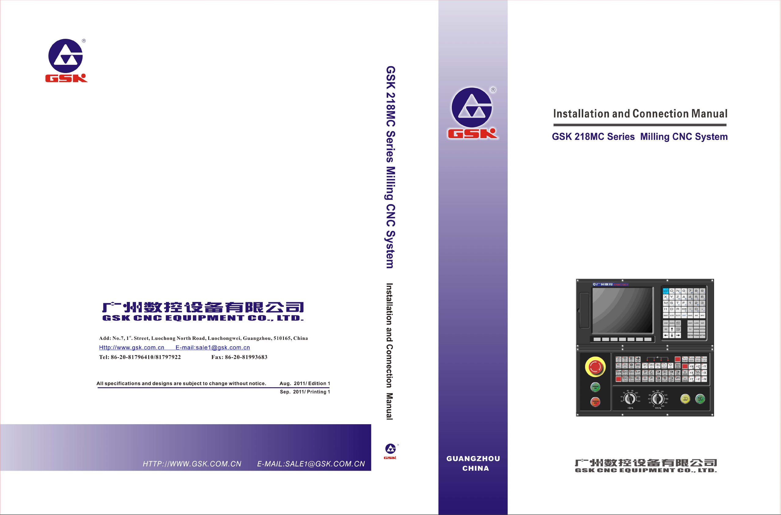
z WRT and WRT.NOT codes are the coil drive code of the output relay and internal relay, but
the input relay can not be used.
z The paratactic WRT command can be used multiply, but it can not output with double coil.
Refer to the following programming:
RD X002.1
X002.1 Y003.7
( )
F100.3 G120.0
( )
WRT Y003.7
RD.NOT F100.3
WRT G120.0
Fig. 4-1-1
4.2 AND, AND.NOT Codes
Mnemonic symbol and function
Table 4-2-1
Volume I Programming
Mnemonic symbol Function
AND Logic AND
AND.NOT Logic AND after the specified
state is NOT
Code explanation
z Connect 1 contact with series connection by using AND, AND.NOT code. The numbers of
series connection contacts are unconstrained, and this code can be used for dozens of times.
Refer to the following programming:
RD X002.1
X002.1 Y003.7
F100.3 X008.6
( )
AND.NOT F100.3
AND X008.6
WRT Y003.7
Fig. 4-2-1
4.3 OR, OR.NOT Codes
Mnemonic symbol and function
Table 4-3-1
Mnemonic symbol Function
OR Logic OR
OR.NOT Logic OR after the specified state is NOT
Code explanation
z Connect 1 contact with series connection using the OR and OR.NOT code.
19
Page 35

Installation and Connection Manual of GSK218MC CNC System
z OR, OR.NOT is started from the step of this code; it can be connected with series connection
with the abovementioned RD, RD.NOT code step.
Refer to the following programming:
Volume I Programming
X002.1 Y003.7
F100.3
VolumI Programming
4.4 OR. STK Code
Mnemonic symbol and function
Mnemonic symbol Function
OR. STK
Code explanation
z OR.STK code is the separate code without any address.
Refer to the following programming:
X002.1 Y003.7
1
F100.3
2
R022.1
3
X002.2
F100.6
( )
RD X002.1
OR.NOT F100.3
WRT Y003.7
Fig. 4-3-1
Table 4-4-1
Right shift one bit of the stacked register after
ST0 and ST1 logic OR
( )
Node N1
OR.STK
OR
RD X002.1
AND.NOT X002.2
RD.NOT F100.3
AND F100.6
OR.STK
OR R 022 .1
W R T Y 003.7
Fig. 4-4-1
There are three branches , and from the left bus to the node N1. The branches and are ①② ③ ① ②
series connection circuit block. When the series connection circuit block is performed between bus to
node or among the nodes, other than the first branch, use the RD code when the following branch is
ended. The branch is not a series connection circuit block, which can be used by the OR code.③
OR. STK and AND. STK are the code without operation component, which indicates the OR , AND
relationships between circuit blocks.
4.5 AND. STK Code
Mnemonic symbol and function
Table 4-5-1
Mnemonic symbol Function
AND.STK
Code explanation
Right shift one bit of the stacked memory after ST0 and
ST1 logic AND
20
Page 36

Chapter Four PLC Basis Code
z Use the AND. STK coded when the branch circuit (parallel circuit block) is connected with
series connection with the front of the circuit. The start of the branch is used RD, RD.NOT
code. Use the AND. STK code is connected with series connection with the front of the circuit
Volume I Programming
after the series connection circuit block is executed.
z AND. STK code is the separate code without any address.
Refer to the following programming:
X002.1 Y003.7
R100.0
R100.3
( )
F100.3
G003.3
R009.7
X011.0
Block
1
Block
2
RD X 002 .1
OR.NOT F100.3
OR.NOT X011.0
RD R 10 0.0
AND.NOT R100.3
RD G 00 3.3
AND R009.7
OR .S T K (1)
AND.STK (2)
Fig. 4-5-1
As for the abovementioned ladder diagram and command table, OR.STK indicates parallel ⑴
connection of the series connection circuit block in the block , AND.STK expresses the series ②⑵
connection between circuit block and .①②
21
Page 37

Installation and Connection Manual of GSK218MC CNC System
CHAPTER FIVE PLC FUNCTION CODE
Volume I Programming
When the basis command code is not easy to compile some operations of the machine tool, the
function command codes can be simplified it.
Table 5-1 (218MC PLC function command code)
VolumI Programming
Serial
number
1 END1
2 END2
3 CALL Call subprogram 21 DIFU Rising edge detection
4 CALLU
5 SP Subprogram 23 COMP Binary number comparison
6 SPE End of subprogram 24 COIN Consistency comparison
7 SET Setting 25 MOVN Data transfer
8 RST Resetting 26 MOVB Transfer of one byte
9 JMPB Sign skip 27 MOVW Transfer of two bytes
10 LBL Sign 28 XMOV
11 TMR Timer 29 DSCH Binary data search
12 TMRB Regular timer 30 ADD Binary addition
13 TMRC Timer 31 SUB Binary subtraction
Name Function
st
The 1
program end
The 2
level sequence
nd
level sequence
program end
Call the subprogram
without any condition
Serial
number
Name Function
19 ROT Binary rotation control
20 SFT Register shift
22 DIFD Trailing edge detection
Binary indexed data
transfer
14 CTR Binary counter 32 ANDF Logic AND
15 DEC Binary decode 33 ORF Logic OR
16 COD Binary code conversion 34 NOT Logic NOT
17 COM
18 COME
Control of the concentric
line
End of the concentric line
control
35 EOR Exclusive OR/ XOR
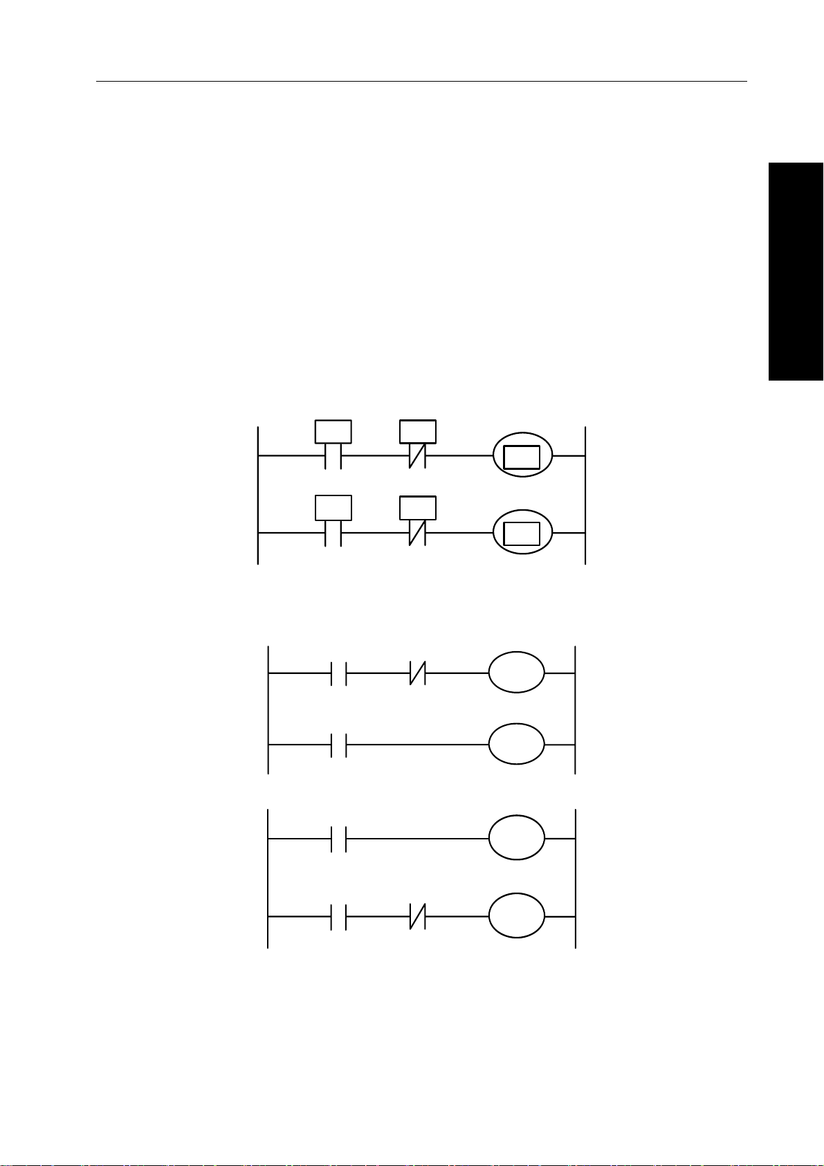
5.1 END1 (End of the 1st Level Sequence Program)
Function
This function can be specified once in sequence program at the end of the 1
can be performed at the beginning of the 2
nd
level program when the 1st level program does not
execute. The first program can be compiled up to 500 steps.
st
level program, or it
22
Page 38

Format
Chapter Five PLC Function Code
Fig. 5-1-1
5.2 END2 (The End of the 2nd Sequence Program)
Function
It specifies at the end of the 2nd level program.
Format
END2
Fig. 5-2-1
5.3 CALL (Call Subprogram)
Function
Call one specified subprogram
It owns the following characters and limitations:
Subprogram can be nested and called other subprograms up to 18 layers, as for the endless
repetition caused by the closure call, the system may alarm. The system allows that the maximum
subprogram call number is 100 for controlling the performance data value. The subprogram call can
st
not be performed at the 1
SPE, or before SP, the system can not be performed, and then alarms.
level program. The code or network wrote between END2 AND SP, or after
Volume I Programming
Format
Control condition
Parameter
indicated as 0~99.
ACT
CALL
ACT=0, next code after performing CALL
ACT=1, call subprogram of the specified subprogram number
Subprogram
number
Fig. 5-3-1
Subprogram number: specify the called subprogram number. The subprogram number is
5.4 CALLU (Call Subprogram Without Condition)
Function
Call one specified subprogram without any condition
23
Page 39

Installation and Connection Manual of GSK218MC CNC System
It owns the following characters and limitations:
Subprogram can be nested and called other subprograms up to 18 layers, as for the endless
repetition caused by the closure call, the system may alarm. The system allows that the maximum
subprogram call number is 100 for controlling the performance data value. The subprogram call can
Volume I Programming
not be performed at the 1
SPE, or before SP, the system can not be performed, and then alarms.
st
level program. The code or network wrote between END2 AND SP, or after
Format
VolumI Programming
CALLU
Parameter
Subprogram serial number: specify the called subprogram number, its range is 0~99.
Subprogram
number
Fig. 5-4-1
5.5 SP (Subprogram)
Function
SP is used to generate a subprogram. The subprogram number is regarded as its name. The range of
the subprogram is specified by the SP code and the aftermentioned SPE code together.
Notice
1. The subprogram should be compiled after END2.
2. Another subprogram can not be set inside one subprogram.
Format
SP
Parameter
Subprogram number: specify a called subprogram mark number, its range is 0~99.
Subprogram
number
Fig. 5-5-1
5.6 SPE (End of Subprogram)
Function
* Specify the range of the subprogram when the SPE and SP are used together.
* The control will return to the main program of the called subprogram when this function code
is performed.
* The subprogram should be compiled after END2.
Figure format
SPE
Fig. 5-6-1
24
Page 40

For example
Chapter Five PLC Function Code
CALL P33
END2
SP P33
SPE
5.7 SET (Replacement/Setting)
Function:
Set 1 in the specified address.
Format:
Volume I Programming
Fig. 5-6-2
ACT
SET
Controllable condition
ACT=0, the state of the add.b remains invariable.
ACT=1, the add.b is set to 1.
Parameter
Add.b: setting component address bit can be treated as the output coil, Add = Y, G, R, K and A.
Add.b
Fig. 5-7-1
(Address)
5.8 RST (Resetting)
Function:
Set 0 on the specifying place.
Format:
ACT
RST
Add.b
(Address)
Fig. 5-8-1
Controllable condition
ACT=0, the state of the add.b remains invariable.
ACT=1, add.b is set to 0.
25
Page 41

Installation and Connection Manual of GSK218MC CNC System
Parameter
Add.b: resetting component address can be treated as output coil, Add = Y, G, R, K and A.
5.9 JMPB (Mark Number Skip)
Volume I Programming
Function:
JMPB immediately transfers the control to program following with mark number in the ladder diagram
programming.
VolumI Programming
The characters and limitations are shown below:
* Multiple skip codes can be shared with the same mark number.
st
* The skip can not be performed each other between the 1
* The skip can not be performed among the subprograms.
* Rebound is allowable, but users that should hold the endless cycle may be caused by it.
* The skip can not be performed between main program and subprogram.
Format:
level and the 2nd level programmes.
ACT
JMPB
Destination
mark number
Fig. 5-9-1
Controllable condition
ACT=0, Do not skip, it performs the next code after JMPB.
ACT=1, Perform the next code after the mark number when the skip jumps to the specified mark
number.
Parameter
Lx: Specify a skip object mark number. Any value (from 0 to 99) can be specified.
5.10 LBL (Mark Number)
Function
Specify one mark number in the ladder diagram, namely, JMPB specifies a skip object.
It is very important to notice that one mark number with xx only can be specified once using LBL. It
may alarm if it uses repeatedly.
Format
LBL
Mark number
Fig. 5-10-1
Parameter
xx: Specify a skip object mark number, its range is 0~99.
26
Page 42

For example
Chapter Five PLC Function Code
5.11 TMR (Timer)
Function
Delay conducting timer.
Format
ACT
JMPB 33
LBL 33
JMPB 33
Fig. 5-10-2
TMR
TIMER (Timer
Fig. 5-11-1
number)
Volume I Programming
(W)
Controllable condition
ACT=0, close the timer.
=1, start the timer.
ACT
Refer to the following figure for details:
ACT
W
TIMER= Setting time
Fig. 5-11-2
Parameter
TIMER: The timer number indicates by xxx (it expresses by numbers from 0 to 127).
Output
W: Output coil. W=1 when it reaches to the resetting value, W=0 means it does not reach to it.
Note: TIMER performs once each 8ms, its setting unit is ms, and 8ms is the performance radix, complete 8ms if it is
insufficient. For example: the setting is 54ms, 54=6*8+6, complete 2ms, the actual performance is 56ms. The
time of the timer is set in the [TMR] of the [PLCPAR] under the program-controlled interface. The sequence
number of the timer may be detected its range by the system directly. The alarm may occur when the sequence
number repeats or exceeds its range.
27
Page 43

Installation and Connection Manual of GSK218MC CNC System
5.12 TMRB (Fixed Timer)
Function
Volume I Programming
Delay conducting timer.
Format
VolumI Programming
Controllable condition
ACT=0, close the timer
=1, start the timer
ACT
Refer to the figure for details:
ACT
TMRB
ACT
W
Timer
accuracy
Timer
number
Fig. 5-12-1
TIMER=Setting time
Fig. 5-12-2
Presetting
time
(W)
Parameter:
TIMER: Fix the timer number, it is indicates by xxx (it expresses by number from 0 to 127).
Table 5-12-1 (Timer accuracy)
Timer
accuracy
Setting
number
Setting time range Error range
8ms 0 From 8ms to 524.280s Scan period from 0 to the 1st level program
48ms 1 From 48ms to 31.456min Scan period from 0 to the 1st level program
1s 2 From 1s to 546 min Scan period from 0 to the 1st level program
10s 3 From 10s to 182 h Scan period from 0 to the 1st level program
1min 4 From 1min to 1092 h From 0 to 1s
1ms 5 From 1ms to 65.4s Scan period from 0 to the 1st level program
Presetting time
The time setting of the fixed timer, its numerical range is: 0~65535.
Output
W: Output coil. W=1, when it reaches to the presetting. W=0, when it does not reach.
Note: As for the sequence of the timer, the system may check its range automatically, if the repeated sequence or out
of the range, the system may alarm. The presetting time in timer is solidified in the ROM along with the ladder
diagram, so, the time of the timer only can be changed by modifying the ladder diagram file.
5.13 TMRC (TIMER)
Function
Delay conducting timer
Format
28
ACT
TMRC
Timer
accuracy
Fig. 5-13-1
Timer
number
(W )
Page 44

Controllable condition
ACT=0, close the timer
=1, start the timer
ACT
Refer to the following figure for details:
ACT
W
TIM E R =Setting tim e
Chapter Five PLC Function Code
Volume I Programming
Fig. 5-13-2
Parameter
TIMER: The timer number indicates by xxx (xxx expresses by numbers from 0 to 127).
Table 5-12-1 (Timer accuracy)
Timer
accuracy
Setting
number
The range of setting time Error range
8ms 0 From 8ms to 524.280s Scan period from 0 to the 1st level program
48ms 1 From 48ms to 31.456 min Scan period from 0 to the 1st level program
1s 2 From 1s to 546 min Scan period from 0 to the 1st level program
10s 3 From 10s to 182 h Scan period from 0 to the 1st level program
1min 4 From 1min to 1092 h From 0 to 1s
1ms 5 From 1ms to 65.4s Scan period from 0 to the 1st level program
Output
W: Output coil. W=1, when it reaches to the presetting, W=0, when it does not reach to it.
Note: The time of the timer is set in the [TMR] in the [PLCPAR] controlling by the program surface. TMRC and TMR
timers are shared with a same address, so, the TMRC and TMR timers can not be repeatedly used. The system
may automatically check the range of the sequence of the timer. It may alarm when the sequence number is
repeated or exceeded its range.
5.14 CRT (Binary Counter)
Function
The data in the counter are binary system, which have the following functions based upon the
applications
1) Presetting counter
If the count reaches to the output signal of presetting value, preset the numerical value.
2) Ring-counter
When the counter reaches to the presetting value, it inputs the count signal and resets the
initial value and performs the count again.
3) Addition and subtraction counter
This is treated as the forward-backward counter, which can be used both addition and
subtraction.
4) The selection of the initial value
The initial value can be regarded as 0 or 1.
29
Page 45

Installation and Connection Manual of GSK218MC CNC System
Format
CNO
COUNTER
Counter
number
(W )
Volume I Programming
VolumI Programming
CTR
UPDOWN
RST
ACT
Fig. 5-14-1
Controllable condition
Specify initial value (CN0)
CN0=0, counter begins with 0.
CN0=1, counter begins with 1.
Specify rising or descending counter (UPDOWN):
UPDONW=1, subtraction counter
UPDOWN=0, addition counter
Reset (RST):
RST=0, release the reset
RST=1, reset: W resets to 0, and the counter value reset to initial value. The RST is set
to 1, as long as the reset is required.
ACT=1: Count performs when ACT is at the rising edge.
ACT=0: Counter does not operate, W will not change.
Parameter
COUNTER: Specify the number of the counter, which is indicated by xxx (it expresses by the
numbers from 0 to 127).
Output
W: Coil output, W=1, when it reaches to the presetting value.
Note 1: The system may automatically check its range of the sequence number of the timer, it may alarm if the
sequence is repeated or exceeded its range.
Note 2: The current value of the timer may automatically reset, after the ladder diagram is converted and downloaded.
Reset the counter by the pulse signal before counting for ensuring the reliable of the counter.
5.15 DEC (Binary Decoding)
Function
DEC can be decoded for the binary system code data, one of the consecutive data of the specified
8-bit (1 type) or 16-bit (2 types) is same as the code data. The corresponding output data bit is 1; the
output data is 0 without any same number.This code is used for the data decode of M or T function.
Format
30
ACT
DEC
Length
Format
specifying
S1 code
data
address
S2
decode
specifying
number
Fig. 5-15-1
S3
decode
result
address
Page 46

Controllable condition
ACT=0: Reset all of the output bits.
=1: Perform the data decode; the treatment result is set at the output data address.
ACT
Parameter
Length: Set the dimension of the code data at the 1
0001: The code data is binary system code data of one byte.
0002: The code data is binary system code data of two bytes.
S1: Code data address. Supply an address of the storage code data.
S2: Decoding specifying number. Specify the 1
be decoded (1 byte) or 16-bit (two bytes).
S3: Decode result address. Specify an address output the decoding result. The register area
must be output with one byte or two bytes areas.
For example:
ACT
DEC
Chapter Five PLC Function Code
st
bit data of the parameter.
st
bit with the consecutive number of the 8-bit to
1 F10 8 R4
Fig. 5-15-2
Volume I Programming
When ACT
When ACT
=1, F10=8, R4=0000,0001;
=1, F10=9, R4=0000,0010;
………………………….
When ACT
=1,F10=15, R4=1000,0000;
5.16 COD (Binary System Code Conversion)
Function:
COD code may automatically produce a corresponding table under its function block when it inputs
the data capacity, which is used for inputting the conversion table data for the user. 10 grids of each
row in this table, it calculates based upon the quotient +1 if it can not be exactly divided, but the
capacity data does not change, and then the address of the table number may not display.
Format
Length1
format
RST
ACT
COD
specifying
table
Length2 data
capacity of the
conversion
S1 conversion
input data
address
S2 conversion
output data
address
(W)
Fig. 5-16-1
Table 5-16-2
S1
S2
S1
S2
012 9
XXX YYY AAA
10 11 12 N-1
………
………
………
……………… ……… ………
………
UUU
31
Page 47

Installation and Connection Manual of GSK218MC CNC System
Controllable condition
Reset (RST):
RST=0, Do not reset.
Volume I Programming
RST=1, W resets, the error may output.
Working code (ACT):
=0: Do not perform the COD.
ACT
=1: Perform the COD. The value of the “conversion input data address (S1)” is regarded as
ACT
VolumI Programming
the table number of the conversion table, the corresponding conversion data of the table number
is taken out from conversion table to output the “output address to the conversion data (S2)”.
Conversion
input data
address
(S1)
Conversion table
0
1
Conversion
data
XXX
YYY
Table
number
1 YYY
Conversion
data output
address (S2)
2
……
N-1
AAA
……
UUU
Fig. 5-16-2
Parameter
Length1: Specify the byte number of the binary system data of the conversion data in the conversion
table.
1: Binary system of 1 byte.
2: Binary system of 2 bytes.
Length2: The capacity of the conversion table data. Each conversion table capacity can not more
than 100, it is 100 bytes when 1 type format is specified; it is 100 bits when 2 bytes format are
specified. The total capacity of the entire COD codes conversion table should be less than 512 bytes.
S1: The data in the conversion table can be taken out by the specifying table number, and the
address of the specifying table number is regarded as the input address of the conversion data. This
address should be supplied a register with one byte.
S2: The output address of the conversion data. Specify the byte numbers of the register in the form
specification beginning with the address.
Output
If the abnormal occurs during the COD code performs, W=1, it indicates that the error issues.
Note: The capacity of the conversion data table is up to 100 bytes (bits), this table is compiled between the parameter
conversion data output address and error output (W).
32
Page 48

5.17 COM (Concentric Line Control)
Chapter Five PLC Function Code
Function
COM specifies the control until the coil working within the public end code COME range. The system
may alarm if the public end code does not specified.
Format
ACT
COM
COME
( W )
( W )
The performance
range of the COM
command
Fig. 5-17-1
Controllable condition
When ACT=0, the coil within the specified range is cut off without any condition (W=0).
When ACT=1, it is same as the COM code that does not perform any operation.
Note 1: Do not specify another COM code within the range of one COM code.
Note 2: When the ACT = 0 of the COM, the coil within the specified range WRT NOT is set to 1 at any time (WRT NOT
= 1).
Note 3: The function codes, such as JMPB, END1, END2, CALL, CALLU, LBL, SP, SPE, COM and COME, can not be
used between COM and COME, otherwise the system may alarm.
Volume I Programming
5.18 COME (Concentric Line Control End)
Function
This code is specified the controllable range of the concentric control line code (COM), which can not
be used separately; it must be used with COM together.
Format
COME
Fig. 5-18-1
5.19 ROT (Binary Rotation Control)
Function
It is used for the revolving control, such as the tool post and rotation workpiece. The code is with
some functions, refer to the following:
1. Select the revolving direction with the short path.
2. Count the steps from the current position to the objective one; or count the steps from the previous
position of the current one to the previous position of the objective one.
3. Count the position number at the objective previous position or the steps at the objective previous
position.
33
Page 49

Installation and Connection Manual of GSK218MC CNC System
Format
Volume I Programming
CNO
DIR
POS
INC
ROT
position address
Rotary table
Current position
address
S1
S2
Objective position
address
S3
Calculation result
output address
(W)
S4
VolumI Programming
ACT
Fig. 5-19-1
Controllable condition
Specify the initial number of the rotary table (CN0):
CNO=0, counter begins with 0.
CNO=1, counter begins with 1.
Check whether the short path can be selected the rotation direction (DIR)
DIR=0, do not select, the selection direction is only positive.
DIR=1, select, the selection direction can be divided into positive or negative.
Specify the operation condition (POS):
POS=0, counting objective position
POS=1 the previous position of the counting object
Specify the position numbers and steps (INC):
INC=0, counting position number. Specify INC=0 and POS=1 if the previous position of the
objective one is to be calculated.
INC=1 counting steps. Perform the code (ACT) when the code INC=1 and POS=0, if the distance
between the current position and the objective one is to be calculated.
Performance code (ACT):
ACT= 0, do not perform the ROT code. W is without change.
=1, perform the ROT code. Generally, set the ACT=0, if the operation is to be required, set
ACT
the ACT=1.
Parameter
S1: Supply the rotary position number.
S2: Supply the address storing the current position.
S3: Specify the address (or code value) storing the objective position. For example, store the address
of the T code outputting from the CNC.
S4: The calculation outputs to address, compute the steps to be rotated of the rotary, which reaches
to the objective position or the previous position. Always check whether the ACT is 1 when using the
calculation result.
Output
W: Rotation direction output. It outputs to the W by the short-circuit rotation direction, its direction is
positive (FOR) when W=0; it is the negative direction (REV) when W=1. The definitions of the FOR
and REV are shown below, the increase direction of the position number of the revolving table is
positive (FOR); it is the negative direction in the decrease state. The address of W can be selected
freely, however, if the W results should be used, always check the condition of the ACT=1.
34
Page 50

For example: One revolving table is shown below:
Current position
1
2
3
Position D
-+
4
Chapter Five PLC Function Code
12
11
10
Position A
Volume I Programming
5
Position C
6
Position B
9
8
Fig. 5-19-2
CNO
ROT
DIR
POS
INC
ACT
W
Fig. 5-19-3
The short path rotation is performed, and the numbers of the previous position of the objective one is
then calculated.
Current position number S2=1, revolving index position number S1
=12, CNO=1, DIR=1, POS=1 and
INC=0
Wherein:
S3=10, S4
S3=8, S4
S3=5, S4
S3=3, S4
=11, W=1, when the objective position is A in the ACT = 1.
=9, W=1, when the objective position is B in the ACT = 1.
=4 and W=0, when the objective position is C in ACT = 1.
=2 and W=0 when the objective position is D in the ACT = 1.
5.20 SFT (Register Displacement/Shifting)
Function:
This code can be shifted 1 byte (8-bit) based upon the digits specifying by the code parameter each
time. The “1” overflown from cycle shifting will be added from the negative direction, for example, the
top bit “1” is overflown when shifting to left, the lowest bit supplies “1”, vise versa.
Format:
Fig. 5-20-1
35
Page 51

Installation and Connection Manual of GSK218MC CNC System
Controllable condition
Specify the shifting direction (DIR)
DIR=0, left shift
Volume I Programming
DIR=1, right shift
State specifying (CONT)
CONT=0, do not perform the cycle shifting
CONT=1, perform the cycle shifting
Reset (RST)
VolumI Programming
Reset shifting output data (W=1) is (W=0)
RST=0, W does not reset
RST=1, W resets (W=0)
Performance condition (ACT)
ACT=0, do not perform the SFT code.
ACT=1, perform the shifting, set ACT to 0 after the code is performed, if only 1 bit is moved.
Parameter
S1: Set the shifting data address, it composes of one storage area by 1 byte.
Length: it is a 4-digit, which is shown in the following figure:
0 0A
L
L Moving digit
each time
A Moving state
Fig. 5-20-2
L: its range is 0~8
A: it is treated as bit-parameter, it is always shifted when ACT =1 during A =0, and it moves once each
period.
ACT is regarded as the pulse signal when A = 1, and when the value turns into 1 from 0, it moves
once.
Output
W: “1” state does not move out when the W = 0 shifting operation is performed.
“1” state moves out when the W = 1 shifting operation is performed.
5.21 DIFU (Rising Edge Detection)
Function:
This code is set the output signal to 1 during the scan period of the input signal rising edge.
Format
ACT
DIFU
L Rising edge
number
( W )
36
Fig. 5-21-1
Page 52

Chapter Five PLC Function Code
Controllable condition
Input signal: The output signal is set to 1 at the rising edge (01) of the input signal.
Output signal: The output signal keeps to 1 during one scan period of the ladder diagram when the
function code is performed.
Parameter:
L: The range of the rising number is 0~255. The system alarm may occur when another DIFU code or
DIFD code is used the same number in the ladder diagram.
Operation
12 34
ACT
Performance
period
Volume I Programming
OUT
Fig. 5-21-2
The system may automatically check the range of the series number of the rising edge, as for the
repeated series number or the exceeding range, the system alarm may occur.
5.22 DIFD (Descending Edge Detection)
Function:
This code outputs 1 signal of one scan period when inputting the signal descending edge.
Format
ACT
DIFD
Controllable condition:
Input signal: The output signal is set to 1 at the descending edge (10) of the input signal.
Output signal: The state in the output signal keeps one scan period of the ladder diagram when this
function code is performed.
Parameter:
L: The range of the descending edge number is 0~255. The system alarm may occur when another
DIFU code or DIFD code is used the same number in the ladder diagram.
Operation:
L Descending
edge number
Fig. 5-22-1
(W )
12 34
ACT
OUT
Performance
period
Fig. 5-22-2
The system may automatically check the range of the series number of the descending edge, as for
the repeated series number or the exceeding range, the system alarm may occur.
37
Page 53

Installation and Connection Manual of GSK218MC CNC System
5.23 COMP (The Comparison of the Binary Number)
Function:
Volume I Programming
Compare the dimensions of two binary number data. Specify the enough bytes to store the input data
and comparison data in the memory block.
Format:
VolumI Programming
Controlled condition
ACT=0, Do not perform the COMP code. W value is invariable
=1, Perform the COMP code
ACT
Parameter
Length: Input the specified format (constant or address) and the specified data length (1 byte or 2
bytes) of the data.
ACT
COMP
Length
format
specifying
Fig. 5-23-1
S1 input
data
address
S2
comparison
data address
(W)
0 0
Format
specifying
0: Constant
1: Address
Data length
Specifying
1: 1 byte length
2: 2 bytes length
Fig. 5-23-2
S1, S2: The contents both the comparison 1 and comparison 2 can be regarded as constant and
address number.
Address number: R, X, Y, F, G, K, A, D and C
Output:
W =0: Inputting data
> comparison data
W = 1: Inputting data ≤ comparison data
5.24 COIN (Consistency Comparison)
Function:
This code can be detected whether the input value and comparison value are consistent.
Format:
ACT
COIN
Controllable condition:
ACT=0, Do not perform the COIN code. W value is invariable.
=1, Perform the COIN code.
ACT
Parameter
Length: Input the specified format (constant or address) and the specified data length (1 byte or 2
Length
format
specifying
Fig. 5-24-1
S1
Input value
S2
Comparison
value address
(W)
38
Page 54

bytes) of the data.
Chapter Five PLC Function Code
0 0
Format
specifying
0: Consta n t
1: Address
Data le n g th
specifying
1: 1 byte length
2: 2 bytes length
Fig. 5-24-2
S1: The input data can be specified both the constant and storage address.
S2: Compare the storage address of the data.
Output:
W: W = 0: input value ≠ comparison value
W = 1: input value = comparison value
5.25 MOVN (Data Transmission)
Function:
The data of the source address or the specified binary data is transferred to the destination address.
Format of the figure:
ACT
MOVN
Length
new byte
number
Fig. 5-25-1
S1
transfer the
resource
address
S2
transfer the
destination
address
(W)
Volume I Programming
Controllable condition
ACT=0, No data.
=1, the byte specified by the quantity is transferred.
ACT
Parameter:
Length: the byte numbers or data number to be transferred.
S1: Resource start address or constant.
Select the transfer form based upon the S1:
1. If the S2 is single byte address, S1 is the constant, the resolution of the S1 based upon the byte is
copied to the address where it is corresponding Length type at the beginning with S2; the S1
should be evaluated based upon the bit, if S2 is the bit address; the bit address corresponding
Length begins with the S2 address.
2. The address type both S1 and S2 will not be considered whether it is matched, which is transferred
the data by the byte address.
S2: Destination start address.
39
Page 55

Installation and Connection Manual of GSK218MC CNC System
For example:
ACT
MOVN
2 S1 S2
( W )
Volume I Programming
Fig. 5-25-2
1. When S1 is regarded as constant 5, and the S2 is treated as R60, then R60=00000101,
R61=00000101.
2. When S1 is regarded as constant 5, and the S2 is treated as D60, then D60=5, D61=5
VolumI Programming
3. When S1 is address D50, and S2 is treated as D60, then D60=D50.
W=1, the specified quantity bytes are transferred.
W=0 No data transfer
The quantity range that exceeds the parameter type is detected when transferring, the system alarm
may occur.
5.26 MOVB (Transmission of 1 Byte)
Function:
The MOVB code transfers the 1 byte data to a specified destination address from a specified
resource address.
Figure format:
ACT
MOVB
S1
transfer the
resource
address
Fig. 5-26-1
S2
transfer the
destination
address
( W )
Controllable condition:
ACT=0, No data transfers
=1, 1 byte is transferred.
ACT
Parameter
S1: Resource address or constant
If the S2 is single byte address, the S1 should be copied to the S2 address based upon the byte value;
if S2 is bit address, the S1 should be copied to the S2 lower byte address based upon the byte value.
S2: Destination address
5.27 MOVW (Transmission of Two Bytes)
Function
MOVW code transfers the 2 bytes data to a specified destination address from a specified resource
address.
Figure format
ACT
MOVW
S1
transfer
resource
address
Fig. 5-27-1
S2
transfer
destination
address
(W)
40
Page 56

Chapter Five PLC Function Code
Controllable condition
ACT=0, No data transfers.
=1, 1 byte is transferred.
ACT
Parameter
S1: Resource address or constant
S2: Destination address
5.28 XMOV (Binary Indexed Data Transmission)
Function
This function code is used to read or write the data from the data table. The data number
(tablecapacity) in this table can be specified by address; the data table can be operated by PLC
based upon the user’s setting during operating.
Format:
RW
XMOV
RST
format specifying
Length
data table capacity
storage address
S1
table head
S2
the address of data
S3
input/output data
address
S4
the storage address
of the table number
( W )
Volume I Programming
ACT
Fig. 5-28-1
Controllable condition
Specify the operation (read or write) (RW)
RW=0: Read the data from the data table.
RW=1: Write the data to the data table.
Reset (RST)
RST=0: Release the reset
RST=1: Reset W=0.
Perform the code (ACT)
ACT
=0: Do not perform the XMOV code, W keeps invariable.
=1: Perform XMOV code.
ACT
Parameter
Length: The format specifies the length of the transmission data.
1: 1 byte length.
2: 2 bytes length.
S1: The data capacity storage address of the data table is used to store the data capacity of the data
table; the occupied byte number should be suitable for the specified length of the Length. The valid
range of the data is determined by the specified byte length of the Length 1 format.
1 byte length: from 1 to 512.
2 byte length: from 1 to 256, that is, 256×2
=512 bytes, which is the capacity of the PLC data table.
S2: Set the address of the data table head. The storage area of the data table = byte length × data
number of its table. The address of the table head should be the value in which is set inside the data
table.
S3: Input/output address. Set and place the address from the reading when the data is read. Set and
place the address from writing when the data is write. Its byte numbers should be suitable from the
41
Page 57

Installation and Connection Manual of GSK218MC CNC System
setting of the Length format. This address is defined as D register.
S4: Storage address of the table number. It is used to store the table number to be read or write. It
occupied bytes should be suitable for the specifying in the Length. If the setting of the table number is
Volume I Programming
more than the data registered in the S1, it outputs W=1 in a wrong way.
Actual transmission address = head address + table number, the table number is 0 (S1-1); The actual
transmission address can not be exceeded the data list.
Output:
VolumI Programming
When the value in the table number exceeds the S1, W=1, the read or write of the data table does not
perform.
W=0, without error
W=1, with error
5.29 DSCH (Binary Data Index)
Function:
This function code can be use for indexing the binary data in the data table. The data number (table
capacity) in the data table can be specified by address. In this case, the table capacity still can be
changed even if the program is written into ROM.
Format
REP
DSCH
format specifying
Length
data table capacity
storage address
S1
S2
data head address
S3
index data address
S4
index result output
address
(W )
RST
ACT
Fig. 5-29-1
Controllable condition
Detection repetition (REP)
REP=0: Perform DSCH code, start to search it from the first address of the data table, it will not
consider the destination data may generate repeatedly; it may stop the search outputting its address
when detecting the destination data at the first time. W=1, if the indexed data does not find.
REP=1: Perform DSCH code. If the indexed data does not find or it has two or above data, W=1.
Reset (RST)
RST=0, Release the reset.
RST=0: Reset W=0.
Performance code (ACT)
=0: Do not perform DSCH code, W keeps invariable.
ACT
ACT
=1: Perform DSCH code. Output its table number if the indexed data is found; if it is
not found or it has two more above data, W=1.
42
Page 58

Chapter Five PLC Function Code
Parameter
Length: Format specifies the length of the index data.
1: 1 byte length
2: 2 bytes length
S1: Data number storage address of the data table. The byte length specified by this address is
distributed the storage area for the requirement of the byte. The data number of the data table is
n+1 (table head is 0, the end of the table is n).
S2: Set the data table head address.
S3: Set the input address of the index address.
S4: The address output of the index result. Actual address = head address + table number, table
number is 0
~(S1-1), the actual address can not exceed the data table. After indexing: output
its number from the list if the index data is found. The table number is outputted to the index result
output address of which the required storage byte number should be suitable for the specified format.
Output
W=0, Find the indexed data.
W=1, Do not find the indexed data.
5.30 ADD (Binary Addition)
Volume I Programming
Function:
This function code is used for the add operation of the 1 byte or 2 bytes binary data. The addend data
and the add operation output the data should be set the storage address with the corresponding byte
length.
Format
RST
ACT
ADD
Length1
format
specifying
S1
addend
address
(address or
constant)
address
S2
addition
S3
calculation
result output
(W)
Fig. 5-30-1
Controllable condition
Reset (RST):
RST=0: Release the reset.
RST=1: Reset W=0.
Performance code (ACT)
=0: Do not perform ADD code, W keeps invariable.
ACT
ACT
=1: Perform ADD code.
Parameter:
Length: Specify the data length (1 byte or 2 bytes) and the specifying method of the addend (constant
or address).
0 0
Format
specifying
0: Constant
1: Address
Fig. 5-30-2
Data length
specifying
1: 1 byte length
2: 2 bytes length
43
Page 59

Installation and Connection Manual of GSK218MC CNC System
S1: Specify the storage addend address.
S2: The specifying method of the addend is determined by the specification of the Length.
S3: Specify the output operation address.
Output
Volume I Programming
W=0: Operation is normal.
W=1: Operation is abnormal.
When the add operation result exceeds the specified data length, W=1
VolumI Programming
5.31 SUB (Binary Subtraction)
Function
This function code is used for the subtraction of the 1 byte or 2 bytes binary data. The minuend data
and the subtraction output data should be set the storage address with the corresponding byte length.
Format
RST
ACT
SUB
specifying
Length1
format
address
S1
minuend
(address or
constant)
address
S2
Subtrahend
S3
Operation
result output
(W)
Fig. 5-31-1
Controllable condition
Reset (RST):
RST=0: Release the resetting.
RST=1: Reset W=0.
Performance code (ACT):
ACT
=0: Do not perform the SUB code, W keeps invariable.
=1: Perform the SUB code.
ACT
Parameter:
Length: Data length specified (1 or 2 bytes) and the addend specifying method (constant or address).
0 0
Format
specifying
0: Constant
1: Address
Data length
specifying
1: 1 byte length
2: 2 bytes length
Fig. 5-31-2
S1: Specify and store the minuend address.
S2: The specifying method of the subtractor is determined by Length.
S3: Specify and output the address of the operation result.
Output
W=0: Normal operation.
W=1: Abnormal operation.
The subtraction result exceeds the specified data length, W=1
44
Page 60

5.32 ANDF (Bit-by-bit AND)
Chapter Five PLC Function Code
Function
This code is performed the AND with a constant (or the content from the address B) from the content
of the address A, and its result is stored to address C.
Format
ACT
ANDF
Length
Format
specifying
S1
Address A
S2
Constant or
address B
S3
Address C
Fig. 5-32-1
Controllable condition
ACT=0: Do not perform ANDF code.
=1: Perform the ANDF code.
ACT
Parameter
Length: Specify the data length (1 byte or 2 bytes), input the data format (constant or address).
0 0
Format
specifying
0: Constant
1: Address
Data len gth
specifying
1: 1 byte length
2: 2 bytes lenght
Fig. 5-32-2
Volume I Programming
S1: Specify the input data that will to be performed by AND. The address is then begins and the data
length is consistent with the Length.
S2: The input data is performed with the one of the AND. When the format specifying is selected the
address, the address is then started, and the data length is consistent with the length.
S3: It is used for storing the address of ANDF operational result. The result from the ANDF is stored
from this address, and the data length is consistent with the one of the Length.
For example: When the address A and B have the following data, which are shown below:
Address A
1 1 1 0 0 0 1 1
Address B
0 1 0 1 0 1 0 1
The operational result of the ANDF is shown below:
Address C
0 1 0 0 0 0 0 1
45
Page 61

Installation and Connection Manual of GSK218MC CNC System
5.33 ORF (Bit-by-bit OR)
Function
This code is performed the OR with a constant (or the content from the address B) from the content of
Volume I Programming
the address A, and its result is stored to address C.
Format
VolumI Programming
ACT
ORF
Length
format
specifying
S1
Address A
S2
Constant or
address B
S3
Address C
Fig. 5-33-1
Controllable condition
ACT=0: Do not perform the ORF code.
=1: Perform the ORF code.
ACT
Parameter
0 0
Format
specifying
0: Constant
1: Address
Data length
specifying
1: 1 byte length
2: 2 bytes length
Fig. 5-33-2
Length: Specify the data length (1 byte or 2 bytes), input the data format (constant or address).
S1: Specify the input data that will to be performed by NOT. The address is then begins and the data
length is consistent with the length.
S2: The input data is performed with the one of the OR. When the format specifying is selected the
address, the address is then started, and the data length is consistent with the.ength.
S3: It is used for storing the address of ORF operational result. The result from the ORF is stored
from this address, and the data length is consistent with the one of the length..
For example: When the address A and B have the following data, which are shown below:
Address A
1 1 1 0 0 0 1 1
Address B
0 1 0 1 0 1 0 1
The operational result of the ORF is shown below:
Address C
1 1 1 1 0 1 1 1
46
Page 62

5.34 NOT (Bit-by-bit NOT)
Chapter Five PLC Function Code
Function: This code is reversed to each content in address A, and store the result to the address B.
Format:
ACT
NOT
Length
format
specifying
S1
Address AS2Address B
Fig. 5-34-1
Controllable condition
ACT=0, Do not perform the NOT code.
ACT
=1, Perform the NOT code.
Parameter
Length: Specify the data length (1 byte or 2 bytes)
0 00
Data length
specifying
1: 1 byte length
2: 2 bytes length
Fig. 5-34-2
S1: The input data is reversed bit-by-bit. The address is started and the data length is consistent with
the length.
S2: It is used for outputting NOT operational result. The result of the NOT operation starts to store
from this address, and the length of the data is consistent with the one of the length.
For example:
When the address A and B have the following data, which are shown below:
Address A
Volume I Programming
1 1 1 0 0 0 1 1
The operation result of the NOT is shown below:
Address B
0 0 0 1 1 1 0 0
5.35 EOR (Exclusive OR)
Function:
This code is performed the Exclusive OR with a constant (or the content from the address B) from the
content of the address A, and its result is stored to address C
Format
ACT
EOR
Length
Format
specifying
S1
Address A
Fig. 5-35-1
S2
Constant or
address B
S3
Address C
47
Page 63

Installation and Connection Manual of GSK218MC CNC System
Controllable condition
ACT=0: Do not perform the EOR code.
=1: Perform the EOR code.
ACT
Volume I Programming
Parameter
Length: Specify the data length (1 byte or 2 bytes), input the data format (constant or address).
0 0
VolumI Programming
S1: Specify the input data that will to be performed by Exclusive OR. The address is then begins
and the data length is consistent with the length.
S2: The input data is performed with the one of the Exclusive OR. When the format specifying is
selected the address, the address is then started, and the data length is consistent with the length.
S3: It is used for storing the address of EOR operational result. The result from the EOR is stored
from this address, and the data length is consistent with the one of the length
For example: When the address A and B have the following data, which are shown below:
Address A
Address B
The operational result of the EOR is shown below
Address C
Format
specifying
0: Constant
1: Address
Data length
specifying
1: 1 byte length
2: 2 bytes length
Fig. 5-35-2
1 1 1 0 0 0 1 1
0 1 0 1 0 1 0 1
1 0 1 1 0 1 1 0
48
Page 64

Chapter Six The Compilation Limit of the Ladder Diagram
CHAPTER SIX THE COMPILATION LIMIT OF THE LADDER
DIAGRAM
1. The program should with the codes END1 and END2, which is regarded as the end symbol of
2. The parallel output is only output instead of multi-level output.
3. The result output address in the overall basis code, output function code can not be set to the
4. The vertical hovering, the node point does not connect to the following node and the parallel
5. The start network does not connect directly between different vertical lines in the same row;
6. The upper embossment can not be accepted inside the network, that is, the parallel network
This is regarded as syntax error, and the system alarm may occur, which is as follow:
st
the 1
level and 2nd level program, and the END1 should be performed before END2.
following address:
1) Counter presetting address DC, timer presetting address DT.
2) The address systems from K0 to K5 are used, user can not define it.
3) The address systems among the GA63, R510 and R511 are used, user can not define
it.
4) X address and F address on the I/O input port.
conducting line is performed the parallel connection to the node network, will generate the
node or network, which can not be performed. So, the system alarm occurs.
one of row does not consecutively connect to the vertical line. As for this case, the system can
not be treated, and therefore the system alarm occurs.
generates on several nodes on one certain row, and any row of it can not be connected to this
parallel network. The system alarm may issue.
(W)
Volume I Programming
Fig. 6.1
(W)
(W)
(W)
(W)
(W)
(W)
49
Page 65

Installation and Connection Manual of GSK218MC CNC System
Volume I Programming
50
Page 66

Chapter One Controllable Axis
Volum e Ⅱ Function
VOLUME II FUNCTION EXPLANATION
51
Page 67

Installation and Connection Manual of GSK218MC CNC System
Volum e Ⅱ Function
52
Page 68

Chapter One Controllable Axis
CHAPTER ONE CONTROLLABLE AXIS
1.1 The output of the axis movement
Brief The movement state of each axis can be output to the PLC.
Signal Axis movement signal
MV1~MV4 (F017#0~F017#3)
[Type] Output signal
[Function] These signals are indicated that one controllable axis is being moved.
MV1: X axis is being moved.
MV2: Y axis is being moved.
MV3: Z axis is being moved.
MV4: A axis is being moved.
[Output condition]
The signal turns into 1 in the following case:
z The corresponding axis has been moved.
The signal turns into 0 in the following case:
z The corresponding axis has been stopped.
The signal of the axis movement direction
MVD1~MVD4(F019#0~F019#3)
[Type] Output signal
[Function] These signals are indicated as the movement direction of one controllable
axis.
MVD1: The movement direction of X axis
MVD2: The movement direction of Y axis
MVD3: The movement direction of Z axis
MVD4: The movement direction of A axis
[Output condition] “0” indicates the corresponding axis moves along with the negative
direction, “1” indicates the corresponding axis moves along with the positive
direction.
Note:
These signals are kept invariable during stopping, which indicates the axis movement direction
before stopping.
Signal address
F017
F019
#7 #6 #5 #4 #3 #2 #1 #0
MV4 MV3 MV2 MV1
MVD4 MVD3 MVD2 MVD1
Volum e Ⅱ Function
53
Page 69

Installation and Connection Manual of GSK218MC CNC System
1.2 Servo Ready Signal
Signal Servo ready signal
SA(F000#6)
[Type] Output signal
[Function] SA signal turns into 1 after the servo is ready. As for the axis that with brake, the brake is
released when the signal is outputted. It is braked when this signal does not output.
Signal address
F000
Volum e Ⅱ Function
#7 #6 #5 #4 #3 #2 #1 #0
SA
54
Page 70

Chapter Two Ready for Operation
CHAPTER TWO READY FOR OPERATION
2.1 ESP
Brief: The machine immediately stops by pressing the ESP button on the operation panel of the
machine tool.
Red
ESP button
Fig. 2-1
The button is locked after pressing; the releasing methods are differing from the manufactures.
Usually, the button can be released by left-rotation.
Signal ESP Signal
ESP ( G001.0 )
[Type] Input signal
[Function] The machine immediately stops after inputting the ESP signal.
[Function] The CNC is reset and in the ESP state when the ESP signal becomes 1.
Signal address
G001
ESP
2.2 CNC Overtravel Signal
Brief: The limit switch operates, and the tool decelerates and stops when the tool movement exceeds
the stroke end set by the machine tool limit switch, the overtravel alarm is then displayed.
Signal Overtravel signal
L1~+L5(G012#0~G012#4)
+
Volum e Ⅱ Function
-L1~-L5(G013#0~G013#4)
[Type] Input signal
[Function] It indicates the controllable axis has been reached to the stroke limit. Each direction of
each controllable axis has this signal. The + and – are expressed the direction of the signal name, the
digit is corresponding with the controllable axis.
L
1: the Xth axis overtravel
2: the Y
3: the Z
4: the 4
5: the 5
th
axis overtravel
th
axis overtravel
th
axis overtravel
th
axis overtravel
+ overtravel
- overtravel
55
Page 71

Installation and Connection Manual of GSK218MC CNC System
[Operation] When the signal is “0”, the operations of the controllable unit are shown below:
* All of the axes are decelerated in the automatical operation, even if only the overtravel
signal of one axis turns into 1, the alarm occurs and stops.
* The axis with movement signal 1 is decelerated and stopped in the manual operation,
the axis after stopping can be moved along with the negative direction.
* The movement direction of the axis is memorized once its overtravel signal turns into 1.
Before eliminating the alarm, this signal axis can not moved along with this direction, even if the
signal becomes 0.
Signal address
G012
+L5
+L4 +L3 +L2 +L1
G013
Volum e Ⅱ Function
2.3 Alarm Signal
-L5
-L4 -L3 -L2 -L1
Brief: When the alarm occurs in the CNC, which displays on the screen, and its alarm signal is set to
1.
Signal Alarm signal
AL(F001#0)
[Type] Output signal
[Function] The alarm signal indicates that the following alarms are displayed when the CNC is in the
alarm state:
a) P/S alarm
b) Overtravel alarm
c) Servo alarm
[Output condition] The alarm signal is 1 in the following conditions:
―― CNC is in the alarm state
The alarm signal is 0 in the following situation:
―― Clear the alarm by the CNC resetting
Signal address
#7 #6 #5 #4 #3 #2 #1 #0
F001
AL
2.4 Selection of the Operation Method
Signal Detection signal in the operation method
F003#0~F003#7
[Type] Output signal
[Function] It indicates the selected operation method.
Signal address
#7 #6 #5 #4 #3 #2 #1 #0
F003
56
MZRO MEDT MMEM MRMT MMDI MJ MH MINC
Page 72

Chapter Two Ready for Operation
2.5 State Output Signal
Cutting feed signal
CUT(F002#6)
[Type] Output signal
[Function] This signal indicates that it is being performed the automatical cutting feed.
[Output condition] The signal is set to 1 in the following conditions:
In the automatical cutting feed (linear interpolation, arc interpolation, helical interpolation, thread
cutting, skip cutting or cutting in the canned cycle)
Notice:
1. This signal does not output when the feed is in the dwell state.
2. This signal can be outputted during interlocking or the federate is 0.
Signal address
F002
#7 #6 #5 #4 #3 #2 #1 #0
CUT
Volum e Ⅱ Function
57
Page 73

JOG feed The feed axis and direction selection signal on the operation panel is set to 1 in the JOG
Volum e Ⅱ Function
Installation and Connection Manual of GSK218MC CNC System
CHAPTER THREE MANUAL OPERATION
3.1 JOG Feed/Incremental Feed
Brief
mode. The machine is consecutively moved along the selected axis in its direction.
Incremental feed The feed axis and direction selection signal on the operation panel is set to 1 in
the incremental feed mode. The machine moves one step along the selected axis in its direction; the
least distance of the machine movement is the least input increment, each step has the least input
increment with 10, 100 or 1000 folds.
JOG feed and incremental feed are absolutely same, other than the feed distance selection method.
In JOG feed, the machine can be consecutively feed when the feed axis (
J3 and -J3) and direction selection signal are set to 1. In incremental feed, the machine is single
step feed. The JOG feedrate can be adjusted by its override disk.
The single-step distance can be selected by the incremental step
G026#0~G026#3.
Signal Feed axis and direction selection
+J1~+J4(G27#0~G27#3)
-J1~-J4(G28#0~G28#3)
[Type] Input signal
[Function] Select the required feed axis and direction in the JOG feed or incremental feed. The +
and – in the signal name are indicated as feed direction, the digit is corresponding with the
controllable axis.
+J1, -J1, +J2, -J2, +
J
1: the Xth axis feed
2: the Y
3: the Z
4: the A
[Operation] When the signal is set to 1, the controllable unit is shown below:
* The controllable unit can be moved the specified axis along the specified direction when the JOG
feed or incremental feed is enabled.
In JOG feed, the controllable unit consecutively moves the controllable axis when the signal is set to
1.
* In the incremental feed, the controllable unit makes that the specified axis feeds based upon the
specified step distance, and then it stops. The controllable unit may not stop feeding even if this
signal is set to 0 during the axis feed. Move the axis again, and the signal will be set to 0 then to 1.
Manual rapid feed selection signal
RT(G024#7)
[Type] Input signal
[Function] Select the rapid traverse rate of the JOG feed or increment feed.
58
th
axis feed
th
axis feed
th
axis feed
+ Feed
- Feed
Page 74

Chapter Three Manual Operation
When the signal turns into 1, the operation of the controllable unit is shown below:
z The controllable unit performs the JOG feed or increment feed at the rapid traverse rate. The
rapid traverse override is enabled.
z The signal shifts to 0 from 1 or is reverse, and its feedrate decreases to 0 during the JOG feed
or increment feed. The feed axis and the direction selection signal can be kept to 1 during the
acceleration or deceleration.
Signal address
G024
#7 #6 #5 #4 #3 #2 #1 #0
RT
G027
+J4 +J3 +J2 +J1
G028
-J4 -J3 -J2 -J1
3.2 MPG (Manual Pulse Generator) / Single Step Feed
Volum e Ⅱ Function
Brief In the MPG/single step feed mode, the machine tool can be slightly moved by rotating the
MPG or single-stop operation. The machine tool movement axis can be selected by the MPG
feed axis signal or axis movement signal.
Signal Single-step feed amount signal selection
G026#0~G026#3)
[Type] Input signal
[Function] The move distance from the pulse is generated by pressing the axis movement
key once during this signal is selected the single-step feed.
Signal MPG feed amount signal selection
(G026#4~G026#6)
[Type] Input signal
[Function] The move distance from a pulse is generated by rotating each unit from the MPG.
59
Page 75

Installation and Connection Manual of GSK218MC CNC System
CHAPTER FOUR REFERENCE POSITION RETURN
4.1 Manual Reference Position Return
Brief The machine tool moves along with the specified direction and returns to the reference
position by setting the parameter No. 7#3~#7 in the mode of the manual reference position return.
The selected axis from the panel buttons is only indicated the one of the specified zero return and it is
regardless of the axis move.
The following signals are related with the manual reference position return:
Table 4-1-1
Volum e Ⅱ Function
Deceleration signal of reference position return
End signal of reference position return
Signal
End signal of reference position return
ZP1~ZP4(F016#0~F016#3)
[Type] Output signal
[Function] This signal shows that the machine tool has been held in the reference position
of the controllable axis.These signals are one-to-one corresponding with the axes.
ZP1 End signal of reference position return along with X axis
ZP2 End signal of reference position return along with Y axis
ZP3 End signal of reference position return along with Z axis
ZP4 End signal of reference position return along with A axis
[Output condition] The signal becomes 1 when the following states are displayed:
z The manual reference position return has been completed, and its current position is performed
in the in-position area.
z The automatical reference position return (G28) has been completed, and its current position is
performed in the in-position area.
z The detection of the reference position return has been completed, and its current position is
performed in the in-position area.
The signal becomes 0 when the following states are displayed:
z When the machine tool moves from the reference position.
z When the ESP signal occurs
z When the servo alarm generates.
Return to the zero deceleration signal detection
DECX(G017#0)DECY(G017#1) DECZ(G017#2)DECA(G017#3)
[Type] Input signal
[Function] These signal decreases the move speed of the manual reference position return, so that
it approximates to the reference position at the low speed.
Manual reference position return
DECX
、DECY、DECZ、DECA
ZP1
、ZP2、ZP3、ZP4
Table 4-1-2
60
Page 76

Chapter Four Reference Position Return
4.2 Return to the Reference Position Detection Signal
The detection allowance signal of the 1st reference position
PREF10---PREF13 (G056#0----#3)
The detection allowance signal of the 2
PREF20---PREF23 (G057#0----#3)
The detection allowance signal of the 3
PREF30---PREF33 (G058#0----#3)
The detection allowance signal of the 4
PREF40---PREF43 (G059#0----#3)
[Type] Input signal
[Function] When this signal is set to 1, the end signal (F42, F43 and F44) of the reference
position return is enabled.
These signals are one-to-one corresponding with the axes.
PREF*0 Allowance signal of reference position detection along with X axis
PREF*1 Allowance signal of reference position detection along with Y axis
PREF*2 Allowance signal of reference position detection along with Z axis
PREF*3 Allowance signal of reference position detection along with A axis
nd
reference position
rd
reference position
th
reference position
Table 4-2-1
Volum e Ⅱ Function
End signal of the 1st reference position return
ZP11---ZP14 (F041#0---#3)
End signal of the 2
nd
reference position return
ZP21---ZP24 (F042#0---#3)
End signal of the 3rd reference position return
ZP31---ZP34 (F043#0---#3)
th
End signal of the 4
reference position return
ZP41---ZP44 (F044#0---#3)
[Type] Output signal
[Function] This signal shows that the machine tool has been held in the reference position of
the controllable axis.
These signals are one-to-one corresponding with the axes.
Table 4-2-2
ZP*1 End signal of reference position return along with X axis
ZP*2 End signal of reference position return along with Y axis
ZP*3 End signal of reference position return along with Z axis
ZP*4 End signal of reference position return along with A axis
[Output condition] This signal is enabled when the detection allowance signal (G57, G58 and
G59) of the reference position is set to 1. The signal becomes 1 when the following states are
displayed.
z The manual reference position return has been completed, and its current position is
performed in the in-position area.
61
Page 77

Installation and Connection Manual of GSK218MC CNC System
z The automatical reference position return (G30) has been completed, and its current
position is performed in the in-position area
z The detection of the reference position return has been completed, and its current position
is performed in the in-position area.
The signal becomes 0 when the following states are displayed:
z The detection allowance signal (G57, G58 and G59) of the reference position is set to 0
z The machine tool moves from the reference position.
z The ESP signal occurs
z The servo alarm generates.
4.3 Area Detection Signal
Volum e Ⅱ Function
Area detection signal
AQ1—AQ3 (F045#0---#2)
[Type] Output signal
[Function] This signal shows that the machine tool has been held in the area range of the
controllable axis
These signals are one-to-one corresponding with the axes.
Table 4-3-1
nd
AQ1 Detection signal of the 2
reference position area along with Z axis
AQ2 Detection signal of the 3rd reference position area along with Z axis
AQ3 Detection signal of the 4th reference position area along with Z axis
[Output condition]
When the machine tool position is within the area of the stored stroke check 1 (Data parameter
P66~P75 is set the boundary), and without the area of the stored stroke check 2 (Data parameter
P76~P85 or program code can be set this boundary), the signal is then turned into 1; otherwise, it
turns into 0.
Signal address
#7 #6 #5 #4 #3 #2 #1 #0
F016
ZP4 ZP3 ZP2 ZP1
F041
ZP14 ZP13 ZP12 ZP11
F042
ZP24 ZP23 ZP22 ZP21
F043
F044
F045
ZP34 ZP33 ZP32 ZP31
ZP44 ZP43 ZP42 ZP41
AQ3 AQ2 AQ1
G017
DECA DECZ DECY DECX
62
Page 78

G057
G058
G059
Chapter Four Reference Position Return
PREF33 PREF32 PREF31 PREF30
PREF23 PREF22 PREF21 PREF20
PREF43 PREF42 PREF41 PREF40
Volum e Ⅱ Function
63
Page 79

Installation and Connection Manual of GSK218MC CNC System
CHAPTER FIVE AUTOMATICAL OPERATION
5.1 Cycle Start/ Feed Hold
Brief Start the automatical operation (Cycle start): In the storage mode, the automatic operation
start signal ST is set to 1 during the DNC or MDI mode; the CNC enters into the automatic operation
start state, then operates.
Signal ST is ignored in the following conditions:
1. The ST signal is ignored other than the mode of the Auto, DNC and MDI
2. The ST signal is ignored when the feed dwell signal (SP) is set to 1.
3. The ST signal is ignored when the ESP signal (ESP) is set to 1.
4. The ST signal is ignored when the <RESET> key on the MDI is pressed.
Volum e Ⅱ Function
5. The ST signal is ignored when the CNC is in the alarm state.
6. The ST signal is ignored when the automatic operation has been started.
7. The ST signal is ignored when the program restart signal is set to 1.
8. The ST signal is ignored when the CNC is being searched a sequence number.
In the automatic operation, the CNC enters into the feed hold state and stops in the following states:
1. When the feed hold signal (SP) is set to 1.
2. Single block code is ended during the single block operates.
3. MDI operation has been completed.
4. The alarm occurs in the CNC.
5. The single block code has been completed after it becomes the other automatic operations or edit
mode.
In the automatic operation, the CNC enters into the reset state and stops in the following states.
1. When the ESP signal is set to 1.
2. Press the <RESET> key on the MDI.
Automatic operation interruption: The feed hold signal SP is set to 1 during the automatic operation,
the CNC enters into the dwell state and stops. At the same time, the cycle start light STL is cleared to
0, and the feed hold indicator SPL is set to 1. The automatic operation will not restart even if the SP
signal is cleared to 0 again. If the restart automatic operation should be performed again, the SP
signal should be cleared to 0, and then the ST signal is set to 1, then clears to 0.
Signal Cycle start signal
ST(G023#6)
[Type] Input signal
[Type] Start the automatic operation
[Operation] ST is set to 1 in DNC or MDI mode during the automatic operation, the CNC then enters
into the cycle start state and starts to operate,
Feed hold signal
SP(G023#7)
[Type] Input signal
[Function] Automatic operation interruption
[Operation] SP signal is set to 1, and CNC enters into the feed hold state and stops during the
automatic operation. When the SP signal is set to 0, the automatic operation can not be started.
64
Page 80

Chapter Five Automatical Operation
Cycle start indicator signal
STL(F000#5)
[Type] Output signal
[Function] The PLC is entered into the automatic operation start already.
[Output condition] The signal can be set to 1 or 0, which is determined by CNC state, refer to the Fig.
5.1.
Feed hold indicator signal
SPL(F000#4)
[Type] Output signal
[Function] The PLC is entered into the feed hold state already.
[Output condition] The signal can be set to 1 or 0, which is determined by CNC state, refer to the Fig.
5.1.
Automatic operation signal
OP(F000#7)
[Type] Output signal
[Function] The PLC automatic operation is being performed.
[Output condition] This signal can be set to 1 or 0, which is determined by CNC state, refer to the
Fig. 5.1.
Table 5-1
Volum e Ⅱ Function
Cycle start LED
STL
Feed hold LED
SPL
Auto operation LED
OP
Cycle start state 1 0 1
Feed hold state 0 1 1
Auto operation stop state 0 0 0
Reset state 0 0 0
Signal address
G023
#7 #6 #5 #4 #3 #2 #1 #0
SP ST
F000
OP STL SPL
5.2 Reset
Brief: The CNC is reset and entered into the reset state in the following conditions:
1. The ESP signal is set to 1.
2. Press the <RESET> key on MDI
The reset signal RST outputs to PLC when CNC is reset. After the abovementioned conditions are
released, the reset signal RST is set to 0 when it outputs the time set by parameter No.203.
RST
=T
(Reset treatment time) + the setting value of the parameter No.203
reset
Reset
treatm ent
Reset
signal
The setting value of the
T
reset
parameter No.203
Fig. 5-2
In the automatic operation, the automatic operation stops when CNC is reset, and the operation axis
65
Page 81

Installation and Connection Manual of GSK218MC CNC System
decelerates then stops.
The CNC is reset during performing the M, S, T function, the MF, SF and TF signals are set to 0 within
16ms.
RST(F001#1)
[Type] Output signal
[Function] PLC and CNC is already reset, this signal is used for treating the PLC reset.
[Output condition] This signal is set to 1 based upon the following conditions:
1. ESP signal is set to 1.
2. Press the <RESET> key on MDI.
This signal is set to 0 in the following case:
After the abovementioned conditions are released, and then the CNC is reset. The reset signal output
time set by parameter No.203 has been ended.
Signal address
Volum e Ⅱ Function
#7 #6 #5 #4 #3 #2 #1 #0
F001
RST
5.3 Program test
Brief: The automatic operation detection should be firstly performed before machining, which is
tested whether the generated program is correct. When the machine does not operate, the detection
is performed by the change viewing the position display or the actual operation machine tool.
5.3.1 Machine Tool Lock
Brief: Do not move the change of the machine tool monitoring position display.
When all axes of the machine tool lock signal MMLK is set to 1, stop to output pulse to the servo
motor during manual or Auto operation, but the code distribution is still performed, and the absolute
and relative coordinates are also renovated. So, the operator can check whether the code
compilation is correct viewing the change of the monitor position.
The machine tool lock detection signal of all axes
MMLK(F004#1)
[Type] Output signal
[Function] The machine lock signal state of all axes of the PLC
[Output condition] When the signal is set to 1, the machine tool lock signal of all axes is set to 1.
When the signal is set to 0, the machine tool lock signal of all axes is set to 0.
Signal address
F004
#7 #6 #5 #4 #3 #2 #1 #0
MMLK
66
Page 82

Chapter Five Automatical Operation
5.3.2 Dry Run
Brief: The dry run is only enabled to the automatic operation. The machine operates with the
constant feederate instead of performing the one defined in the program. The feedrate is set by data
parameter P86.
This function is used for checking the move of the machine tool when the machine tool does not
install the workpiece.
Signal Dry run signal
DRN(G021#2)
[Type] Input signal
[Function] Dry run enables.
[Operation] when this signal is set to 1, the machine tool moves based upon feedrate set by dry run.
The machine tool moves normally when the signal is set to 0.
Note:
The dry run signal becomes 1 from 0 during the machine operation, and the machine tool operation
speed is the one of the dry run, which is accelerated or decelerated by programming specified speed;
when the dry run signal becomes 0 from 1, the machine tool operation speed is accelerated or
decelerated to the programming specified speed by the dry run speed.
Signal address
G021
#7 #6 #5 #4 #3 #2 #1 #0
DRN
Volum e Ⅱ Function
5.3.3 Single Block
Brief: The signal block operation is only enabled to the automatic operation.
When the single block signal (SBK) is set to 1 during the automatic operation; the CNC enters into the
automatic operation and stops after the current block is executed. In the sequence automatic
operation, the CNC enters into the automatic operation and stops after each block in the program is
performed. The automatic operation is performed again when the single block signal (SBK) is set to 0.
Signal: Single block signal
SBK(G021#1)
[Type] Input signal
[Function] Single block enables.
[Operation] Perform the single block operation when this signal is set to 1.
Single block detection signal
MSBK(F004#3)
[Type] Output signal
[Function] PLC single block signal state
[Motion] The signal is set to 1 in the following condition:
―― When the single block signal SBK is set to 1.
The signal is set to 0 in the following condition:
―― When the single block signal SBK is set to 0.
Perform the normal operation when this signal is set to 0.
67
Page 83

Installation and Connection Manual of GSK218MC CNC System
Note:
1. The operation in the thread cutting
The SBK signal becomes 1 during the thread cutting, the operation is stopped after the thread cutting
st
code is performed before the 1
non-thread cutting block.
2. The operation in the canned cycle
The SBK (when it is set to 1) signal is stopped during the canned cycle instead of the EOB when the
positioning approaches to the drilling and tool-retraction each time. SPL signal becomes 1 when it is
set to 0, which means that it is not performed to the EOB. STL and SPL signals are became 0 and
stopped when a block is performed.
Signal address
G021
Volum e Ⅱ Function
F004
#7 #6 #5 #4 #3 #2 #1 #0
MSBK
SBK
5.4 Skip Optional Block
Brief: In the Auto operation, when a slash is specified at the beginning of the block, and when the
skip optional block signal BDT is set to 1, this block is then ignored.
Signal: The signal of skip optional block
BDT(G021#0)
[Type] Input signal
[Function] Select whether the block with “/” is ignored.
[Motion] In the Auto operation, the block with “/” is ignored when BDT is set to 1; the program is
performed normally when BDT is set to 0.
The detection signal of skip optional block
MBDT(F004#0)
[Type] Output signal
[Function] The state of PLC skip optional block BDT
Signal address
#7 #6 #5 #4 #3 #2 #1 #0
G021
F004
BDT
MBDT
68
Page 84

Chapter Five Automatical Operation
5.5 Program Restart
Brief: The program can be restarted the block from the specified sequence number, after the tool is
damaged or had a rest then stopped. This function also can be used for the rapid program detection
function.
Signal: The signal of program restart
SRN<G021#6>
[Type] Input signal
[Function] Selection program restarts
[Operation] When the program restart signal is set to “1” for searching the sequence number of the
restart block; the CRT screen shifts to the program restart screen. When the program restart signal is
set to “0”, and the automatic operation is enabled, the machine tool moves to the machining restart
point with the dry run speed in turn based upon the setting of the axis sequence. The machining
restarts after the machine tool moves to the restart point.
The signal in the program restart
SRNMV<F002#4>
[Type] Output signal
[Function] It means that the program is being started.
[Output condition] This signal becomes 1:
— When the G21 #6 is set to 1 in the Auto state, the program restart signal is
set to 1.
When this signal becomes 0:
— Program restart sequence end (all of the controllable axis from the machine
Signal address
#7 #6 #5 #4 #3 #2 #1 #0
G021
F002
are moved to the restart point)
SNR
SRNM
Volum e Ⅱ Function
69
Page 85

Installation and Connection Manual of GSK218MC CNC System
CHAPTER SIX FEEDRATE CONTROL
6.1 Rapid Traverse Rate
Brief: 4-gear override (F0, 25%, 50% and 100%) can be used for the rapid traverse rate.
Volum e Ⅱ Function
Fig. 6-1
Feedrate: The actual move speed is gained from which the setting value of the parameter P088~092
multiples the override value, regardless in the Auto or manual operation (it consists of the manual
reference position return and program zero return).
F0 speed: It is determined by parameter P093
Signal: The signal of the rapid traverse rate
Rapid F0 (G025#0)
Rapid F25% (G025#1)
Rapid F50% (G025#2)
Rapid F100% (G025#3)
[Type] Input signal
[Function] It is the rapid traverse override signal.
The code detection signal of the rapid traverse override (G11#0~G11#1)
[Type] Input signal
[Function] It is the code detection signal of the rapid traverse override
[Operation] The code signal corresponding with the following override
Code signal at the rapid traverse rate
RV1 RV2
0 0
0 1
1 0
1 1
Override value
100%
50%
25%
0%
70
Page 86

Chapter Six Feedrate Control
6.2 Feedrate Override
Brief: The override disk can be selected to increase or decrease the programming feedrate by the
percentage. This character is used for the programming detection. For example, when the specified
feedrate in the program is 100mm/min, the override is set to 50%, the machine is then moves at the
speed of 50mm/min.
Signal GSK218MC integration CNC system:
Feedrate FOV1 (X31.3)
Feedrate FOV2 (X31.4)
Feedrate FOV4 (X31.5)
Feedrate FOV8 (X31.6)
Feedrate FOV16 (X31.7)
[Type] Input signal
[Function] Cutting feedrate override signal. Totally 21 gear from 0% to 200%.
[Motion] In the Auto operation, the specified speed by the cutting feed multiplies the override value
selected by this signal, which gains the actual feedrate.
GSK 218MC-H and GSK 218MC-V CNC system:
Code detection signal of the feedrate override (G011#3~G011#7)
[Type] Input signal
[Function] The cutting feedrate rate signal has five binary system code signals corresponding with
its override:
So, the override can be selected based upon the unit of the 10% within the range of the 0~200%.
Note: The feedrate both 218MC-H and 218MC-V are controlled by the feed brand switch.
Volum e Ⅱ Function
6.3 Override Cancellation
Brief: The feedrate override is fixed on 100% by the override cancellation signal.
Signal Override cancellation signal
OVC(G024#1)
[Type] Input signal
[Function] The feedrate override is fixed on 100%.
[Operation] The CNC operation is shown below when the signal is set to 1:
The feedrate override is fixed on 100% regardless of the feedrate override signal.
No affection in the rapid traverse override and spindle speed override.
Signal address
G024
#7 #6 #5 #4 #3 #2 #1 #0
OVC
71
Page 87

Installation and Connection Manual of GSK218MC CNC System
CHAPTER SEVEN MISCELLANEOUS FUNCTION
7.1 M Code Miscellaneous Function
Brief: M code miscellaneous function When the registered M code is operated, the register signal
(F026.0~F033.7) and the strobe signal are sent to the PLC, PLC is started or cut off its relative
functions by these signals.
Basis processing
These signals are used for the following functions:
Table 7-1-1
Volum e Ⅱ Function
Function
M code
miscellaneous
function
Program
address
M**
Output signal
Register signal Strobe signal
M**
(F026#0~F033#7)
(F007
MF
#0)
Response
signal
MRESP
(G063#0)
End signal
FIN(G000#0)
MFIN(G000#1)
(1) It is supposed that the MXX is specified in the program (Suppose the register signal is FYYY.Y)
As for the MXX, if the user does not register it, the alarm may occur. User specify a unique F signal
registering this M code to the system, that is, the code signal from F26 to F33.
(2) If the non M, S and T codes, such as the movement and dwell, are specified with the
miscellaneous function at the same time, the miscellaneous function is then simultaneously
performed. Multiple codes of the miscellaneous function are specified in a block, its codes may
perform in sequence.
(3) When the MXX is performed, the register signal FYY.Y and the strobe signal F007#0 are set to 1,
simultaneously, ensuring the PLC sets the response signal RESP(G063#0) to 0.
(4) PLC is set the end signal MFIN (G000#1) and FIN (G000#0) to 1 when the operation is
performed. If these functions, namely, the M, S and T code miscellaneous functions are performed
simultaneously, the end signal FIN(G000#0) can be set to 1 till all of these functions are executed.
(5) When the MXX is completed, ensuring the PLC is set the response signal MRESP (G63#0) to 1.
(6) M, S and T codes may be performed simultaneously in a block. The CNC can be performed next
block after affirming the end signal FIN is set to 1.
7.2 S Code Miscellaneous Function
Brief: When the S code is performed, the I/O point or analog value control can be set by the bit 2 of
the bit parameter No: 1
The basis processing of the spindle S code I/O point control:
Table 7-2-1
Output signal
S*
Strobe
signal
TF
(F007#2)
Response
signal
SRESP
(G63#1)
End signal
FIN(G00#0)
SFIN(G00#4)
72
Function
S code
miscellaneous
function
Program
address
S*
F address
signal
(F22)
Page 88

Chapter Seven M.S.T Function
S code miscellaneous function explanations are shown below:
(1) It is supposed that SX is specified in the program:
The range of the X is 1~8, the system may alarm if it exceeds its range. S1~S8 separately
corresponds to the F address signal F22#0~#7. (For example, S1 corresponds to the F address
signal F22#0).
(2) If the non M, S and T codes, such as the movement and dwell, are specified with the
miscellaneous function at the same time, the
performed.
(3) When the S1 is performed, the F address signal F22#1 and the strobe signal F007#2 are set to
1, simultaneously, ensuring the PLC sets the response signal RESP(G063#1) to 0.
(4) PLC is set the end signal SFIN (G00#4) and FIN (G00#0) to 1 when the operation is performed.
If these code miscellaneous functions, namely, M, S and T, are performed simultaneously, the end
signal FIN (G00#0) can be set to 1 till all of these functions are executed.
(5) When the S1 is completed, ensuring the PLC is set the response signal SRESP (G63#1) to 1.
(6) M, S and T codes may be performed simultaneously in a block. The CNC can be performed
next block after affirming the end signal FIN is set to 1.
The basic processing of the spindle S code analog value:
miscellaneous function is then simultaneously
Volum e Ⅱ Function
Table 7-2-1
The signal
completion of
the shift
GRAR
(G002#4
)
Response
signal
SRESP
(G063#1)
End signal
FIN(G000#0)
SFIN(G000#4)
Function
S code
miscellaneous
function
Program
address
S****
Output signal
F address signal
S**
(F034#0~#2)
Strobe
signal
TF
(F007#2)
The S code miscellaneous function explanations are shown below:
(1) It is supposed that the SXXXX is specified in program: (The state of F34#0~#2 is determined by
parameter P246~248, and PLC can be performed the processing of the gear step change by this
signal, for example, the parameter P246 is set to 1000, and S500 executes).
(2) If the non M, S and T codes, such as the movement and dwell, are specified with the
miscellaneous function at the same time, the
miscellaneous function is then simultaneously performed.
(3) When the S500 is performed, the F address signal F34#0 and the strobe signal F007#2 are set to
1, simultaneously, ensuring the PLC sets the response signal SRESP(G063#1) to 0
(4) The PLC is set the gear shift signal GRAR (G002#4) is set to 1 when the gear shift is completed.
(5) PLC is set the end signal SFIN (G000#4) and FIN (G000#0) to 1 when the S code miscellaneous
function is performed. If these code miscellaneous functions, namely, M, S and T, are performed
simultaneously, the end signal FIN (G000#0) can be set to 1 till all of these functions are executed
(6) When the S500 is completed, ensuring the PLC is set the response signal SRESP (G063#1) to 1.
(7) M, S and T codes may be performed simultaneously in a block. The CNC can be performed next
block after affirming the end signal FIN is set to 1.
73
Page 89

Installation and Connection Manual of GSK218MC CNC System
7.3 T Code Miscellaneous Function
Brief: T code miscellaneous function: T code should be used with the M code together, for example:
T06M06;
When the T code is performed, the data address (D241) and the strobe signal are sent to PLC, and
PLC starts or cut off its relative functions using these signals.
Basis process
These signals are used for the following functions
Table 7-3-1
Volum e Ⅱ Function
Function
T code
miscellaneous
function
Program
address
T**
Output signal
Data address
T**
(D241)
Strobe
signal
BF
(F007#3)
Response
signal
SRESP
(G63#2)
End signal
FIN(G00#0)
TFIN(G00#5)
(1) It is supposed that the TXX (XX is sent to the data address D241) is specified in the
program:
(2) If the non M, S and T codes, such as the movement and dwell, are specified with the
miscellaneous function at the same time, the
miscellaneous function is then simultaneously
performed. Multiple codes of the miscellaneous function are specified in a block, its code
will be performed in sequence.
(3) The strobe signal F007#3 is set to 1 when performing TXX.
(4) The end signal TFIN (G000#5) and FIN (G000#0) are set to 1 by PLC when the operation is
completed. If these functions, namely, the M, S and T code miscellaneous functions are
performed simultaneously, the end signal FIN(G000#0) can be set to 1 till all of these
functions are executed.
(5) M, S and T codes may be performed simultaneously in a block. The CNC can be performed
next block after affirming the end signal FIN is set to 1.
Signal It is the register signal of the M code miscellaneous function
M00~M99(F026~F033)
The strobe signal of M code miscellaneous function
MFEFD(F007#0)
[Type] Output signal
[Function] These signals are specified the miscellaneous function of the PLC.
[Output condition] Refer to explanation of the “M code miscellaneous function in Section 7.1” for the
output condition and execution process.
Note 1: The following miscellaneous function can be treated in the CNC: they can not be outputted even if they are
specified in the program:
* M98,M99
* The M code for calling subprogram
* The M code for calling the user macro program
Note 2: The encoding signal also can be outputted other than the code signal and strobe signal in the following
miscellaneous function.
,M01,M02,M30
M00
Note 3: The M codes from the M00 to M39 can be supplied based upon the binary encoding.
74
Page 90

Chapter Seven M.S.T Function
For example: M5 is corresponding to the 00000101
M encoding signal
(F009#7)
DM00
DM01
(F009#6)
DM02
(F009#5)
DM30
(F009#4)
[Type] Output signal
[Function] These signals are shown that the miscellaneous function has been
specified actually. The corresponding table between miscellaneous
function and output signal in the program code are shown below:
Table 7-3-2
Program code Output signal
M00 DM00
M01 DM01
M02 DM02
M30 DM30
[Output condition] The M encoding signal is set to 1 when the following conditions are described.
z Specify the corresponding miscellaneous function, and any specified move command and dwell
code is completed at the same block. However, when the end signal of the miscellaneous
function returns before the move code and dwell code, these signals are then not outputted.
The M encoding signal bit is 0 when the following conditions are performed:
z FIN signal bit is 1.
z When it is reset.
The end signal of M code miscellaneous function
MFIN<G000#1>
Response signal of M code miscellaneous function
MRESP<G063#0>
[Type] Input signal
[Function] It means that the M code miscellaneous function is completed.
[Operation] Refer to the “M code miscellaneous function in Section 7.1” for the treatment and
process in the control unit.
The strobe signal of S code miscellaneous function
TF(F007#2)
[Type] Output signal
[Function] These signals are shown that the spindle speed function has been specified actually.
[Output condition] Refer to the “S code miscellaneous function in Section 7.2” for the output
condition and performance process.
The end signal of S code miscellaneous function
SFIN<G000#4>
The response signal of S code miscellaneous function
SRESP<G063#1>
[Type] Input signal
[Function] It means that the S code miscellaneous function is completed.
[Operation] Refer to the “S code miscellaneous function in the Section 7.2” for the treatment and
Volum e Ⅱ Function
75
Page 91

Installation and Connection Manual of GSK218MC CNC System
performance process of the unit.
Tool function strobe signal
BF(F007#3)
[Type] Output signal
[Function] These signals are shown that the tool function has been specified actually.
[Output condition] Refer to the “T code miscellaneous function in Section 7.3” for the output
condition and performance process.
Tool function end signal
TFIN<G000#5>
[Type] Input signal
[Function] It means that T code miscellaneous function is completed.
[Operation] Refer to the “T code miscellaneous function in Section 7.3” for the treatment and
Volum e Ⅱ Function
performance of the control unit.
Miscellaneous function end signal
FIN(G000#0)
[Type] Input signal
[Function] This signal shows the end of the M, S and T code miscellaneous functions.
[Operation] When this signal is 1, refer to the explanations in Section 7.1, 7.2 and 7.3 for the
operation and treatment of the control unit.
Caution
All of these functions abovementioned are shared with one end signal FIN (G000#0); this signal
should be set to 1 after the overall functions are completed.
Signal address
G000
#7 #6 #5 #4 #3 #2 #1 #0
TFIN SFIN
MFIN FIN
G063
F007
SRESP MRESP
BF TF MF
F009
DM00 DM01 DM02 DM30
7.4 Miscellaneous Function Lock
Brief: It is forbidden to perform the specified M, S and T functions. This function is used for detecting
the program even if the code signal and strobe signal are not output.
Signal: Miscellaneous function lock signal
AFL(G021#3)
[Type] Input signal
[Function] This signal selects the miscellaneous function lock. That is, this signal is not permitted to
perform the specified S, T and partition M functions.
76
Page 92

Chapter Seven M.S.T Function
[Motion] When the signal is set to 1, the functions of the control unit are shown below:
1. As for the Auto, DNC and MDI operations, the control unit does not perform the specified
M, S and T functions, namely, the code and strobe signals are not output.
2. This signal is set to 1 after the code signal is output, normally, perform the output
operation till it ends. ( to the manual FIN signal, and the strobe signal is set to 1.)
3. The miscellaneous functions, for example, M00, M01, M02 and M03 can be performed,
even if this signal is set to 1. The overall code, strobe and encoding signals are output
based upon the normal method.
4. The miscellaneous functions M98 and M99 can be performed based upon the normal
method, even if this signal is set to 1, however, the performance result does not
output in the control unit.
Caution: The spindle analog output is still performed even if this signal is set to 1.
The detection signal of miscellaneous function
MAFL(F004#4)
[Type] Output signal
[Function] This signal indicates the state of the miscellaneous function lock signal.
[Output condition] The miscellaneous function lock signal AFL is 1 when this signal is set to 1.
The miscellaneous function lock signal AFL is 0 when this signal is set to 0.
Signal address
G021
#7 #6 #5 #4 #3 #2 #1 #0
AFL
Volum e Ⅱ Function
F004
MAFL
77
Page 93

Installation and Connection Manual of GSK218MC CNC System
CHAPTER EIGHT SPINDLE SPEED FUNCTION
8.1 Spindle Speed Control Method
Brief: GSK218MC divides the spindle into gear spindle and analog spindle based upon the control
method.
1. In the gear spindle, the CNC controls the spindle speed by which the S code turns into
switch value and then outputs to the spindle.
2. In the analog spindle, the CNC controls the spindle speed by which the S code turns into
analog value and then outputs to the spindle.
The I/O point or analog value control can be set by bit 2 of bit parameter No.1.
Volum e Ⅱ Function
8.1.1 Gear Spindle
Brief: The gear spindle means that the spindle S code is controlled by I/O.
Signal
Spindle speed strobe signal
TF(F007#2)
Gear spindle address signal
F22#0~F22#7
[Type] Output signal
[Function] These signals have been indicated that the specified spindle speed function has been
performed actually.
[Output condition] Refer to the “S code miscellaneous function in Section for spindle S code I/O
point control” for the output condition and performance process.
Note: S code range: S1~S8, the alarm may occur if it exceeds its range, S1~S8 are separately corresponding with
the F address signal F022#0~#7. User can refer to three gears (S1, S2 and S3) of the configurated ladder
diagram from the system. So, S4~S8 can not be used, the corresponding ladder diagram should be added if the
user needs.
8.1.2 Analog Spindle
Brief: Analog spindle is that the spindle speed is controlled by the analog voltage value of the CNC.
CNC can be controlled the spindle speed of which the S code turns into the analog voltage value
outputting to the machine’s spindle.
Actual output analog voltage value = spindle controlled S value x spindle override.
Signal GSK218MC integration CNC system:
Spindle override SOV1 (X31.0)
Spindle override SOV2 (X31.1)
Spindle override SOV4 (X31.2)
[Type] Input signal
[Function] This signal specifies that the spindle controls the override change of the S value.
78
Page 94

Chapter Eight Spindle Speed Function
GSK 218MC-H and GSK 218MC-V CNC system:
Spindle override code detection signal (G019#0~G019#2)
[Input] Input signal
[Function] It is the spindle override code detection signal
Spindle override code detection signal has 3 binary system code signals which are corresponding
with the override:
So, the spindle override can be selected based upon the 10% unit within the 50~120%.
When the spindle speed control is performed instead of using the spindle speed override, the setting
override value is 100%.
Notice: The spindle speed override function in the tapping cycle and thread cutting is disabled.
Gear shift treatment
Although the S code is spindle speed, its actual controlled member is spindle motor, and therefore,
the CNC should be affirmed the corresponding relations between spindle motor speed and gear. The
CNC selects the gear shift based upon the defined speed range of each gear shift in advance, as it is
directly selected by S code. The PLC can be selected the corresponding gear shift using its selection
signal (GR3, GR2 and GR1). Simultaneously, the CNC outputs the spindle motor speed based upon
the selected gear shift. Specify the S0
spindle speed in the MDI operation. Two or three speed gear shifts (GR1, GR2 and GR3) can be set
by parameter No.246
~248, and then the gear shift selection signal can be output at the same time.
When the gear shift selection signal changes, the SF signal is simultaneously output.
The meaning of the gear shift signal is shown below:
~S99999 and CNC output corresponding codes with the
Volum e Ⅱ Function
the 2
Table 8-1-2-1
nd
gear the 3rd gear Remark
GR1 Low Low Low: Low speed gear
GR2 High Middle Middle: intermediate speed gear
GR3 High High: high speed gear
· When the code voltage is 10V, spindle speed A at low speed shift (Parameter No246) (min-1)
· When the code voltage is 10V, spindle speed B at the high speed shift (Parameter No.247) (min
(Medium speed gear at the 3
· When the code voltage is 10V, spindle speed C at the high speed shift (Parameter No.248) (min
rd
( the 3
gear).
S code command is performed with the spindle motor speed code voltage (0
rd
gear).
~10V) and the gear shift
selection signal.
The relationships among the GR1, GR2 and GR3 are shown above:
Signal: Gear shift selection signal
GR1,GR2,GR3
<F034#0~#2>
[Type] Input signal
[Function] These signals are informed the gear shift selected by PLC.
[Output condition] Refer to the gear shift method for the explanation of these signals.
Gear shift selection signal (Input)
GR1,GR2,GR3<G002#0~#2>
[Type] Input signal
[Function] These signals are informed the current selected gear shift of the CNC.
[Output condition] Refer to the gear shift method for the explanation of these signals.
-1
)
-1
)
79
Page 95

Installation and Connection Manual of GSK218MC CNC System
Gear shift in-position signal
GEAR<G002#4>
[Type] Input signal
[Function] These signals that are informed the current selected gear shift of the CNC has been
performed its in-position.
[Output condition] Refer to the gear shift method for the explanation of these signals.
Signal address
G002
#7 #6 #5 #4 #3 #2 #1 #0
GEAR
GR3 GR2 GR1
G022
F007
SPOV OVC SMOV
TF
Volum e Ⅱ Function
F034
GR3 GR2 GR1
8.2 Rigid Tapping
Brief: The rigid tapping is synchronized the tapping axis and spindle axis in the common tapping
canned cycle.
The CNC needs to detect the rotation direction signal of the spindle ensuring the direction and
processing of the cutting feed during the rigid tapping (during performing G74 and G84).
Performance processing:
Spindle rotates → Z axis feed tapping → sending the M05 stop code to spindle → after the spindle is
absolutely stopped → sending a reverse code → Z axis retracts to the start → spindle stops
The corresponding ladder diagram should be compiled for carrying out the rigid tapping; inform the
rotation direction of the CNC external spindle.
Signal: Rigid tapping signal
RGTAP(G003#1)
[Type] Output signal
[Function] That this signal informs PLC has been in the mode of the rigid tapping.
[Output condition] RGTAP 1: It is rigid tapping mode at present.
0: It does not tapping mode at present.
Signal address
G003
#7 #6 #5 #4 #3 #2 #1 #0
RGTAP
80
Page 96

Chapter Nine Programming Code
CHAPTER NINE PROGRAMMING CODE
9.1 User Macro Program
Brief: It is very essential to perform the same operation repeatedly for the subprogram, but the
variable, arithmetic, calculation, logic operation and condition branch an be used for the user macro
program function, which is very easy to develop the current program. The machining program can be
called the user macro program by a simple code, as the calling of the subprogram.
O0001 (Main program name)
N10 G50 X100 Z100;
N20 G00 U50 F100;
N30 G01 U0.8;
N40 M61;
N50 G0 X100 Z100;
Subprogram (customized M61)
O9064;
N10 G65 P#1104 Q1;
G65 H82 P20 Q#1004 R1;
…………
G65 H01 P#1001 Q0;
M99 P50;
Fig. 9-1-1
It means that one function is programmed by the user macro, which becomes the general function.
Namely, the data variable (changeable and undefinition data) can be compiled the program. For
example, the user macro program can be used for the composed technology.
Signal: User macro program input signal
UI000~UI015(G054,G055)
[Type] Input signal
[Function] Do not offer any function to the controllable unit. These signals are regarded as one of
the system variable, which is read by the macro program, and it is used for the interface signal
between macro program and PLC.
The corresponding system variables of these signals are shown below:
Table 9-1-1
Signal Address Variable
UI000 G54#0 #1000
UI001 G54#1 #1001
UI002 G54#2 #1002
UI003 G54#3 #1003
UI004 G54#4 #1004
UI005 G54#5 #1005
UI006 G54#6 #1006
UI007 G54#7 #1007
UI008 G55#0 #1008
UI009 G55#1 #1009
UI010 G55#2 #1010
UI011 G55#3 #1011
UI012 G55#4 #1012
UI013 G55#5 #1013
UI014 G55#6 #1014
UI015 G55#7 #1015
UI000~UI015 G54, G55 #1032
Note: #1032 is the variable of the 16-bit, which is composed as follows:
Volum e Ⅱ Function
81
Page 97

Installation and Connection Manual of GSK218MC CNC System
Signal address
#1032
#7 #6 #5 #4 #3 #2 #1 #0
UI007 UI006 UI005 UI004 UI003 UI002 UI001 UI000
#1032
UI015 UI014 UI013 UI012 UI011 UI010 UI009 UI008
User macro program output signal
UO000~UO015
(F054~F055)
UO100~UO131
(F056~F059)
[Type] Output signal
[Function] Do not offer any function to the controllable unit. These signals are regarded as a kind of
variable which is read or written by the user macro program, and it is used for the interface signal
Volum e Ⅱ Function
between macro program and PLC.
The corresponding system variables of these signals are shown below:
Table 9-1-2
Signal Address Variable
UO000 F54#0 #1100
UO001 F54#1 #1101
UO002 F54#2 #1102
UO003 F54#3 #1103
UO004 F54#4 #1104
UO005 F54#5 #1105
UO006 F54#6 #1106
UO007 F54#7 #1107
UO008 F55#0 #1108
UO009 F55#1 #1109
UO010 F55#2 #1110
UO011 F55#3 #1111
UO012 F55#4 #1112
UO013 F55#5 #1113
UO014 F55#6 #1114
UO015 F55#7 #1115
UO000~UO015 F54,F55 #1132
Note
: #1132 is the variable of the 16-bit, which is composed as follows
#7 #6 #5 #4 #3 #2 #1 #0
#1132
UO007 UO006 UO005 UO004 UO003 UO002 UO001 UO000
#1132
UO015 UO014 UO013 UO012 UO011 UO010 UO009 UO008
82
Page 98

Chapter Nine Programming Code
9.2 Canned Cycle
Brief: Canned cycles can be simplified the program. With a canned cycle, a frequently-used
machining operation can be specified in a single block with a G function; without canned cycles,
normally more than one block is required. In addition, the use of canned cycles can shorten the
program to save memory.
Explanations: A canned cycle consists of a sequence of 6 operations:
Operation 1 Positioning a hole position
Operation 2 Rapid traverse up to Point R level
Operation 3 Hole machining
Operation 4 Operation at the bottom of a hole
Operation 5 Retraction to point R level
Operation 6 Rapid traverse up to the initial point
Volum e Ⅱ Function
Operation 1
Operation
2
Operation
3
Operation
4
Initial point
Operation 6
R
Operation 5
Rapid traverse
Cutting feed
Fig. 9-2-1 Canned cycle operation sequence
Spindle control: Output the spindle code of the reverse rotation in some canned cycle.
The following canned cycles are required the spindle control:
Reverse tapping cycle G74 Fine boring cycle G76
Tapping cycle G84 Boring cycle G86
Counter boring cycle G87 Boring cycle G88
Using the frequently-used miscellaneous functions for the spindle control:
Refer to the miscellaneous function explanations.
M03: Spindle positive
M04: Spindle negative
M05: Spindle stop
M19: Spindle orientation
Tapping signal: Output the tapping signal during the tapping cycle. The tapping signal also can be
output when tapping cycle G code is enabled.
Override: The cutting feed override is always set to 100% during tapping.
Feed hold: The move may not stop immediately during tapping when pressing the feed hold key. The
move stops when the tool returns to the R panel.
Dry run: Whether the dry run is enabled during the TDR (bit 5 of parameter No.12) defines tapping.
83
Page 99

Installation and Connection Manual of GSK218MC CNC System
Signal: Tapping signal
TAP<F001#5>
[Type] Output signal
[Function] It informs that the system is in the tapping mode.
[Output condition] This signal is 1:
- When the system is in the tapping cycle mode G74 and G84
- When the system is in the tapping mode G63.
This signal is 0:
- When the system is neither in the tapping cycle mode nor in the tapping
mode
- When the reset or ESP signal is input
Signal address
Volum e Ⅱ Function
F001
#7 #6 #5 #4 #3 #2 #1 #0
TAP
84
Page 100

Chapter Ten Display/Setting
CHAPTER TEN DISPLAY/SETTING
10.1 Clock Function
Brief: The Year, Month and Day are displayed on the setting screen.
The system variable of the user macro program can be read the time.
Read and write can be performed for the time information.
10.2 Display the Operation Record
Brief: This function can be displayed the current error. Operator performs the history records to the
MDI key and signal when the alarm occurs.
10.3 Help Function
Volum e Ⅱ Function
Brief: The CNC alarm and the details of the CNC operation can be displayed on the screen using the
help function.
Detailed information of alarm: The help screen displays the generated alarm and that how to release
the alarm information. However, the information from the P/S alarm is displayed, which is easy to be
distorted or misunderstood.
85
 Loading...