


 Loading...
Xmedia Server
Digital Asset Management System
Configuration Guide
M841-9900-500

Copyright & Trademark Notice
Copyright © 2015, Grass Valley USA, LLC. All rights reserved.
Belden, Belden Sending All The Right Signals, and the Belden logo are trademarks or registered trademarks of Belden Inc. or its affiliated companies in the United States and other jurisdictions. Grass Valley USA, LLC, Miranda, Vertigo Suite, Vertigo XG and Xmedia Server are trademarks or registered trademarks of Grass Valley USA, LLC. Belden Inc., Grass Valley USA, LLC, and other parties may also have trademark rights in other terms used herein.
Terms and Conditions
Grass Valley hereby grants permission and license to owners of the Xmedia Server to use their product manuals for their own internal business use. Manuals for Grass Valley, A Belden Brand products may not be reproduced or transmitted in any form or by any means, electronic or mechanical, including photocopying and recording, for any purpose unless specifically authorized in writing by Grass Valley.
A Grass Valley manual may have been revised to reflect changes made to the product during its manufacturing life. Thus, different versions of a manual may exist for any given product. Care should be taken to ensure that one obtains the proper manual version for a specific product serial number.
Information in this document is subject to change without notice and does not represent a commitment on the part of Grass Valley.
Warranty Policies
Warranty information is available in the Support section of the Grass Valley Web site (www.grassvalley.com).
Document Identification
Title |
Xmedia Server Configuration Guide |
|
|
Part number |
M841-9900-500 |
|
|
SW version |
Vertigo Suite v5.0 |
|
|

Revision History
After the original release date, this document may be updated with edits and then rereleased. The following table tracks the versions of this document.
Revision date |
Description |
|
|
November 28, 2014 |
Original release |
|
|
March 02, 2015 |
Vertigo Suite v5.0 SP1 release |
|
|
April 15, 2015 |
Specified that the values entered in the Xmedia Server’s |
|
Newsroom Control System dialog must be entered as all |
|
uppercase letters (page 7-4). |
|
|

Safety Compliance
This equipment complies with the requirements of CSA/UL/IEC/EN 60950-1, 2nd Ed. + AM1, Safety of information technology equipment.
The power cords supplied with this equipment meet the appropriate national standards for the country of destination.
[fr] Conformité aux normes de sécurité
Cet équipement est conforme aux exigences de CSA/UL/IEC/EN 60950-1, 2e éd. + AM1, Sécurité du matériel informatique.
Les cordons d'alimentation fournis avec l’appareil répondent aux normes nationales appropriées du pays destinataire.
[es] Conformidad en seguridad eléctrica
Este equipo cumple con las exigencias de la CSA/UL/IEC/EN 60950-1, 2a ed. + AM1, Seguridad de los equipos de tecnología de la información.
Los cables de alimentación incluidos con el equipo cumplen con las normas nacionales apropiadas para el país de destino.
[pt] Conformidade de segurança elétrica
Este equipamento está em conformidade com os requisitos da CSA/UL/IEC/EN 60950-1, 2a ed. + AM1, Segurança de equipamento de tecnologia da informação.
Os cabos de alimentação fornecidos com este equipamento encontram as normas nacionais adequadas para o país de destino.

Safety of Laser Modules
This equipment incorporates modules containing Class 1 lasers. These modules are certified by the manufacturer to comply with:
•IEC/EN 60825-1 Safety of laser products
•IEC 60950-1 Safety of information technology equipment
[fr] Sécurité laser
L’appareil comprend des modules laser de classe 1. Ces modules sont certifiés conformes aux normes suivantes par le fabricant :
•IEC/EN 60825-1 Sécurité des appareils à laser
•IEC 60950-1 Sécurité du matériel informatique
[es] Seguridad por los módulos laser
Este equipo incorpora módulos láser de la Clase 1
Estos módulos están certificados por el fabricante para cumplir con:
•IEC/EN 60825-1 Seguridad de los productos láser
•IEC 60950-1 Seguridad de los equipos de tecnología de la información
[pt] Segurança por módulo de laser
Este equipamento incorpora módulos que contêm laser da classe 1. Estes módulos são certificados pelo fabricante em conformidade com:
•IEC/EN 60825-1 Segurança de equipamentos laser
•IEC 60950-1 Segurança de equipamento de tecnologia da informação

Important Safeguards and Notices
This section provides important safety guidelines for operators and service personnel. Specific warnings and cautions appear throughout the manual where they apply. Please read and follow this important information, especially those instructions related to the risk of electric shock or injury to persons.
[fr] Mesures de sécurité et avis importants
La présente section fournit des consignes de sécurité importantes pour les opérateurs et le personnel de service. Des avertissements ou mises en garde spécifiques figurent dans le manuel, dans les sections où ils s’appliquent. Prenez le temps de bien lire les consignes et assurez-vous de les respecter, en particulier celles qui sont destinées à prévenir les décharges électriques ou les blessures.
[es] Medidas de seguridad y avisos importantes
Esta sección proporciona pautas de seguridad importantes para los operadores y el personal de servicio. Advertencias y precauciones específicas aparecen en el manual para su aplicación. Por favor, lea y siga esta importante información, especialmente aquellas instrucciones relacionadas con el riesgo de descarga eléctrica o lesiones a las personas.
[pt] Salvaguardas e avisos importantes
Esta seção fornece diretrizes de segurança importantes para os operadores e pessoal de serviço. Avisos e cuidados específicos estão listados no manual para sua aplicação. Por favor, leia e siga esta informação importante, especialmente aquelas instruções relacionadas ao risco de choque elétrico ou ferimentos.
Symbols and Their Meanings
The lightning flash with arrowhead symbol within an equilateral triangle alerts the user to the presence of dangerous voltages within the product’s enclosure that may be of sufficient magnitude to constitute a risk of electric shock to persons.
The exclamation point within an equilateral triangle alerts the user to the presence of important operating and maintenance/service instructions.
The earth ground symbol represents a protective grounding terminal. Such a terminal must be connected to earth ground prior to making any other connections to the equipment.
The fuse symbol indicates that the fuse referenced in the text must be replaced with one having the ratings indicated.
The presence of this symbol in or on Grass Valley, A Belden Brand equipment means that it has been designed, tested and certified as complying with applicable Canadian Standard Association (CSA) regulations and recommendations for USA/Canada.
The presence of this symbol in or on Grass Valley, A Belden Brand equipment means that it has been designed, tested and certified as complying with applicable Underwriters Laboratory (UL) regulations and recommendations for USA/Canada.
The presence of this symbol in or on Grass Valley, A Belden Brand equipment means that it has been designed, tested and certified as essentially complying with all applicable European Union (CE) directives.
The presence of this symbol in or on Grass Valley, A Belden Brand product means that it complies with safety of laser product applicable standards.

Warnings
A warning indicates a possible hazard to personnel, which may cause injury or death. Observe the following general warnings when using or working on this equipment:
•Appropriately listed/certified mains supply power cords must be used for the connection of the equipment to the mains voltage at either 120 V AC or 240 V AC.
•This product relies on the building's installation for short-circuit (over-current) protection. Ensure that a fuse or circuit breaker for 120 V AC or 240 V AC is used on the phase conductors.
•Any instructions in this manual that require opening the equipment cover or enclosure are for use by qualified service personnel only.
•Heed all warnings on the unit and in the operating instructions.
•Do not use this equipment in or near water.
•This equipment is grounded through the grounding conductor of the power cords. To avoid electrical shock, plug the power cords into a properly wired receptacle before connecting the equipment inputs or outputs.
•Route power cords and other cables so they are not likely to be damaged.
•Disconnect power before cleaning the equipment. Do not use liquid or aerosol cleaners; use only a damp cloth.
•Dangerous voltages may exist at several points in this equipment. To avoid injury, do not touch exposed connections and components while power is on.
•Do not wear rings or wristwatches when troubleshooting high current circuits such as the power supplies.
•To avoid fire hazard, use only the specified fuses with the correct type number, voltage and current ratings as referenced in the appropriate locations in the service instructions or on the equipment. Always refer fuse replacements to qualified service personnel.
•To avoid explosion, do not operate this equipment in an explosive atmosphere.
•This product includes a backup battery. There is a danger of explosion if the battery is replaced incorrectly. Replace the battery only with the same or equivalent type recommended by the manufacturer. Dispose of used batteries according to the manufacturer’s instructions.
•Have qualified service personnel perform safety checks after any service.
[fr] Avertissements
•Un cordon d’alimentation dûment homologué doit être utilisé pour connecter l’appareil à une tension de secteur de 120 V CA ou 240 V CA.
•La protection de ce produit contre les courts-circuits (surintensités) dépend de l’installation électrique du bâtiment. Assurez-vous qu'un fusible ou un disjoncteur pour 120 V CA ou 240 V CA est utilisé sur les conducteurs de phase.

•Dans le présent manuel, toutes les instructions qui nécessitent d’ouvrir le couvercle de l’équipement sont destinées exclusivement au personnel technique qualifié.
•Respectez tous les avertissements figurant sur l’appareil et dans les instructions d’utilisation.
•Ne pas utiliser cet appareil dans l’eau ou à proximité d’un point d’eau.
•Cet équipement est mis à la terre par le conducteur de mise à la terre des cordons d’alimentation. Pour éviter les chocs électriques, branchez les cordons d’alimentation sur une prise correctement câblée avant de brancher les entrées et sorties de l’équipement.
•Acheminez les cordons d’alimentation et autres câbles de façon à ce qu’ils ne risquent pas d’être endommagés.
•Coupez l’alimentation avant de nettoyer l’équipement. Ne pas utiliser de nettoyants liquides ou en aérosol. Utilisez uniquement un chiffon humide.
•Des tensions dangereuses peuvent exister en plusieurs points dans cet équipement. Pour éviter toute blessure, ne touchez pas aux connexions ou aux composants exposés lorsque l’appareil est sous tension.
•Avant de procéder à toute opération d’entretien ou de dépannage visant des circuits à courant élevé (e.g., les blocs d’alimentation), enlevez tous vos bijoux (notamment vos bagues et votre montre).
•Pour éviter tout risque d’incendie, utilisez uniquement les fusibles du type et du calibre indiqués dans la documentation ou sur l’équipement. Confiez le remplacement de fusibles au personnel technique qualifié.
•Ne pas utiliser cet appareil dans une atmosphère explosive.
•L’appareil renferme une pile. Pour réduire le risque d’explosion, vérifiez la polarité et ne remplacez la pile que par une pile du même type, recommandée par le fabricant. Mettez les piles usagées au rebut conformément aux directives du fabricant.
•Après tout travail d’entretien ou de réparation, faites effectuer des contrôles de sécurité par le personnel technique qualifié.
[es] Advertencias
•Un cable de alimentación aprobado deberá ser utilizado para la conexión del equipo a la tensión de red de 120 V CA o 240 V CA.
•Este producto depende de la instalación del edificio para la protección de cortocircuitos (sobre-corriente). Asegúrese que un fusible o un interruptor térmico de 120 V CA o 240 V CA se utiliza en los conductores de fase.
•Todas las instrucciones de este manual que requieren abrir la tapa del equipo se llevará a cabo por personal técnico calificado.
•Respete todas las advertencias en el equipo y las instrucciones de funcionamiento.
•No utilice este producto en el agua o cerca de este.

•Este equipo está conectado a tierra a través del conductor de puesta a tierra de los cables de alimentación. Para evitar una descarga eléctrica, enchufe el cable de alimentación a un tomacorriente debidamente instalado antes de conectar las entradas y salidas del equipo.
•Instale los cables de alimentación y otros cables de forma de evitar ser dañados.
•Desconecte la alimentación antes de limpiar el equipo. No use limpiadores líquidos o aerosoles, utilizar un paño húmedo.
•Pueden existir tensiones peligrosas en varios puntos de este equipo. Para evitar lesiones, no toque las conexiones y componentes expuestos cuando la unidad está con alimentación.
•No use anillos o relojes al solucionar problemas de circuitos de alta corriente como fuentes de alimentación.
•Para evitar el riesgo de incendios, utilice sólo el fusible indicado con el número de tipo correcto, el voltaje y la corriente que se hace referencia en los lugares apropiados en las instrucciones de los servicios o el equipo. Siempre consulte el reemplazo del fusible a personal calificado.
•Para evitar explosiones, no utilice este equipo en una atmósfera explosiva.
•Este producto incluye una batería de reserva. Existe el peligro de explosión si la batería se instala de forma incorrecta. Reemplace la batería únicamente con el mismo tipo o equivalente recomendada por el fabricante. Deshágase de las baterías usadas según las instrucciones del fabricante.
•Deje al personal calificado realizar las verificaciones de seguridad después de un servicio.
[pt] Advertências
•Um cabo de alimentação aprovado deve ser utilizado para ligar o equipamento à tensão da rede de 120 V CA ou 240 V CA.
•Este produto baseia-se na instalação do edifício para proteção por curto-circuito (sobrecarga de corrente). Certifique-se de que um fusível ou disjuntor para 120 V CA ou 240 V CA é utilizado nos condutores de fase.
•Todas as instruções contidas neste manual, que exigem a abertura da tampa do equipamento será realizada por pessoal qualificado.
•Preste atenção a todos os avisos no equipamento e instruções de operação.
•Não use este produto em ou perto da água.
•Este equipamento é aterrado através do condutor de aterramento do cabo de alimentação. Para evitar choque elétrico, conecte o cabo de alimentação a uma tomada devidamente instalada antes de ligar as entradas e saídas do dispositivo.
•Instale os cabos de alimentação e os outros cabos de modo a evitar danos.
•Desligue a alimentação antes de limpar o equipamento. Não use detergentes líquidos ou aerossóis, usar um pano úmido.
•Tensões perigosas podem existir em vários pontos deste equipamento. Para evitar ferimentos, não toque as conexões e componentes expostos quando o aparelho está ligado.
•Não usar anéis ou relógios ao solucionar problemas de circuitos de alta tensão, tais como fontes de alimentação.
•Para evitar o risco de incêndio, utilize apenas o número especificado de fusível de tipo correto de tensão e corrente a que se refere o manual de serviço adequado. Referemse sempre trocar o fusível por pessoal qualificado.
•Para evitar a explosão, não utilize este equipamento em uma atmosfera explosiva.
•Este produto inclui uma bateria de backup. Existe o perigo de explosão se a bateria está instalada incorretamente. Substitua a bateria somente com o mesmo tipo ou equivalente recomendado pelo fabricante. Elimine as baterias usadas de acordo com as instruções do fabricante.
•Deixe o pessoal qualificado executar verificações de segurança depois de um serviço.

Cautions
A caution indicates a possible hazard to equipment that could result in equipment damage. Observe the following cautions when operating or working on this equipment:
•This equipment is meant to be installed in a restricted access location.
•When installing this equipment, do not attach the power cord to building surfaces.
•To reduce the risk of electric shock, do not perform any servicing other than that contained in the operating instructions unless you are qualified to do so. Refer all servicing to qualified service personnel. Servicing should be done in a static-free environment.
•This unit has more than one power supply cord. Disconnect both power supply cords before servicing to avoid electric shock.
•To prevent damage to equipment when replacing fuses, locate and correct the problem that caused the fuse to blow before re-applying power.
•Use only the specified replacement parts.
•Follow static precautions at all times when handling this equipment.
•Products that have no on/off switch, and use an external power supply must be installed in proximity to a main power outlet that is easily accessible.
[fr] Mises en garde
•L’appareil est conçu pour être installé dans un endroit à accès restreint.
•Au moment d’installer l’équipement, ne fixez pas les cordons d’alimentation aux surfaces intérieures de l’édifice.
•Pour réduire le risque de choc électrique, n'effectuez pas de réparations autres que celles qui sont décrites dans le présent manuel, sauf si vous êtes qualifié pour le faire. Confiez les réparations à un technicien qualifié. La maintenance doit se réaliser dans un milieu libre d’électricité statique.
•L’appareil comporte plus d’un cordon d'alimentation. Afin de prévenir les chocs électriques, débrancher les deux cordons d'alimentation avant toute opération d’entretien.
•Pour éviter d'endommager l'équipement lors du remplacement de fusibles, localisez la source de la panne et corrigez la situation avant de rétablir le courant.
•Employez uniquement les pièces de rechange recommandées par le fabricant.
•Veillez à toujours prendre les mesures de protection antistatique appropriées quand vous manipulez l’équipement.
•Les produits qui n'ont pas d’interrupteur marche-arrêt et qui disposent d’une source d’alimentation externe doivent être installés à proximité d'une prise de courant facile d’accès.

[es] Precauciones
•Este equipo está destinado a ser instalado en un lugar de acceso restringido.
•Al instalar este equipo, no sujete el cable de alimentación a la superficie del edificio.
•No realice reparaciones que no se encuentren en las instrucciones de funcionamiento a menos que esté calificado para hacerlo. Confíe las reparaciones a personal técnico calificado. El mantenimiento debe realizarse en un ambiente libre de estática.
•Esta unidad incluye dos cables de alimentación. Desconecte ambas fuentes de alimentación antes de dar servicio, para reducir el riesgo de descarga eléctrica.
•Para evitar daños en el equipo al sustituir los fusibles, primero localizar y corregir el problema que causó que el fusible se funda antes de aplicar la alimentación de nuevo.
•Utilice únicamente repuestos específicos.
•Siga las precauciones DES en todo momento al manipular este equipo.
•Los productos que no tienen interruptor de encendido/apagado, y utilizan una fuente de alimentación externa deben instalarse cerca de una toma de corriente de fácil acceso.
[pt] Precauções
•Este material destina-se a ser instalado em um acesso restrito.
•Quando instalar o equipamento, não fixar o cabo de alimentação em superfícies do edifício.
•Não faça reparações que não estão no manual de instruções, a menos que você estiver qualificado. Solicite a assistência de pessoal qualificado. A manutenção deve ser realizada em um ambiente livre de estática.
•Esta unidade inclui dois cabos de alimentação. Desligue ambas as fontes de alimentação antes de manutenção para reduzir o risco de choque elétrico.
•Para evitar danos ao equipamento ao substituir fusíveis, primeiro localizar e corrigir o problema que causou o fusível fundir antes de aplicar energia novamente.
•Use unicamente partes específicas.
•Siga as precauções DES em todos os momentos ao manusear este equipamento.
•Os produtos que não têm um interruptor de ligar/desligar, e usam uma fonte de alimentação externa devem ser instalados perto de uma tomada elétrica de fácil acesso.

Electrostatic Discharge (ESD) Protection
Electrostatic discharge occurs when electronic components are improperly handled and can result in intermittent failure or complete damage adversely affecting an electrical circuit. When you remove and replace any card from a frame
always follow ESD-prevention procedures:
•Ensure that the frame is electrically connected to earth ground through the power cord or any other means if available.
•Wear an ESD wrist strap ensuring that it makes good skin contact. Connect the grounding clip to an unpainted surface of the chassis frame to safely ground unwanted ESD voltages. If no wrist strap is available, ground yourself by touching the unpainted metal part of the chassis.
•For safety, periodically check the resistance value of the antistatic strap, which should be between 1 and 10 megohms.
•When temporarily storing a card make sure it is placed in an ESD bag.
•Cards in an earth grounded metal frame or casing do not require any special ESD protection.
[fr] Protection contre les décharges électrostatiques (DES)
Une décharge électrostatique peut se produire lorsque des composants électroniques ne sont pas manipulés de manière adéquate, ce qui peut entraîner des défaillances intermittentes ou endommager irrémédiablement un circuit électrique. Au moment de remplacer une carte dans un châssis, prenez toujours les mesures de protection antistatique appropriées :
•Assurez-vous que le châssis est relié électriquement à la terre par le cordon d'alimentation ou tout autre moyen disponible.
•Portez un bracelet antistatique et assurez-vous qu'il est bien en contact avec la peau. Connectez la pince de masse à une surface non peinte du châssis pour détourner à la terre toute tension électrostatique indésirable. En l’absence de bracelet antistatique, déchargez l’électricité statique de votre corps en touchant une surface métallique non peinte du châssis.
•Pour plus de sécurité, vérifiez périodiquement la valeur de résistance du bracelet antistatique. Elle doit se situer entre 1 et 10 mégohms.
•Si vous devez mettre une carte de côté, assurez-vous de la ranger dans un sac protecteur antistatique.
•Les cartes qui sont reliées à un châssis ou boîtier métallique mis à la terre ne nécessitent pas de protection antistatique spéciale.

[es] Protección contra descargas electrostáticas (DES)
La descarga electrostática se produce cuando los componentes electrónicos se manipulan de forma incorrecta pudiendo causar una falla intermitente o total afectando un circuito eléctrico. Al quitar y reemplazar una tarjeta de un chasis siempre siga los procedimientos para prevenir la DES:
•Asegúrese de que el chasis está conectado eléctricamente a tierra a través del cable de alimentación o cualquier otro medio si está disponible.
•Use una pulsera de DES asegurando que tiene buen contacto con la piel. Conecte la pinza de puesta a tierra a una superficie sin pintar del chasis para desviar a tierra cualquier voltaje de DES indeseable. Si ninguna pulsera está disponible, conéctese a tierra tocando la parte metálica sin pintar del chasis.
•Para su seguridad, verifique periódicamente el valor de la resistencia de la pulsera antiestática, que debe estar entre 1 y 10 megaohmios.
•Al guardar temporalmente una tarjeta electrónica asegúrese que está colocado en una bolsa de DES.
•Las tarjetas que están conectadas a un chasis de o caja de metal a tierra, no requieren una protección especial para la DES.
[pt] Proteção contra descargas eletrostáticas (DES)
DES ocorre quando os componentes eletrônicos são manipulados de forma inadequada e pode causar falha intermitente ou completa afetando um circuito elétrico. Remover e substituir um cartão eletrônico do chassi siga sempre os procedimentos para evitar DES:
•Certifique-se de que o chassi é eletricamente aterrado através do cabo de alimentação ou qualquer outro meio, se disponível.
•Utilize uma pulseira DES assegurando que você tenha um bom contato com a pele. Conecte o clipe à terra a uma superfície não pintada do chassi para desviar qualquer tensão indesejável de DES. Se nenhuma pulseira está disponível, faça o aterramento tocando a parte metálica não pintada do chassi.
•Por segurança, verificar periodicamente o valor da resistência da pulseira antiestática, que deve ser entre 1 e 10 megohms.
•Por temporariamente salvar um cartão eletrônico, certifique-se de que ele é colocado em um saco de DES.
•As cartas que estão ligados a um chassis ou caixa de metal ligada à terra, não necessitam de proteção especial para o DES.

Cautions for LCD and TFT Displays
If the LCD or TFT glass is broken, handle glass fragments with care when disposing of them. If any fluid leaks out of a damaged glass cell, be careful not to get the liquid crystal fluid in your mouth or skin. If the liquid crystal touches your
skin or clothes, wash it off immediately using soap and water. Never swallow the fluid. The toxicity is extremely low but caution should be exercised at all times.
[fr] Précautions pour les écrans LCD et TFT
Si l'écran LCD ou TFT est brisé, manipulez les fragments de verre avec précaution au moment de vous en débarrasser. veillez à ce que le cristal liquide n'entre pas en contact avec la peau ou la bouche. En cas de contact avec la peau ou les vêtements, laver immédiatement à l'eau savonneuse. Ne jamais ingérer le liquide. La toxicité est extrêmement faible, mais la prudence demeure de mise en tout temps.
[es] Precauciones para las pantallas LCD y TFT
Si la pantalla LCD o TFT se rompe, retire con cuidado los fragmentos de vidrio cuando se deshaga de ellos. Si hay una fuga de líquido de una celda de vidrio dañado, tenga cuidado que el cristal líquido no entre en contacto con su boca o la piel. Si el cristal líquido toca su piel o su ropa, lávelos inmediatamente con agua y jabón. No ingiera nunca el líquido. La toxicidad es muy baja, pero se debe tener precaución en todo momento.
[pt] Precauções para os LCD e TFT
Se o ecrã LCD ou TFT está quebrado, retire cuidadosamente os fragmentos de vidro ao descartar deles. Se o líquido está vazando de uma célula de vidro danificado tenha cuidado para não tirar o fluido de cristal líquido em sua boca ou pele. Se o cristal líquido toca sua pele ou roupa, lave imediatamente com água e sabão. Nunca engula o líquido. A toxicidade é muito baixa, mas o cuidado deve ser exercido em todos os momentos.
Electromagnetic Compatibility
This equipment has been tested for verification of compliance with FCC Part 15, Subpart B requirements for class A digital devices.
 NOTE
NOTE
This equipment has been tested and found to comply with the limits for a Class A digital device, pursuant to Part 15 of the FCC rules. These limits are designed to provide reasonable protection against harmful interference when the equipment is operated in a commercial environment. This equipment generates, uses, and can radiate radio frequency energy, and, if not installed and used in accordance with the instruction manual, may cause harmful interference to radio communications. Operation of this equipment in a residential area is likely to cause harmful interference in which case the user will be required to correct the interference at his own expense.
This equipment has been tested and found to comply with the requirements of the EMC directive 2004/108/EC:
•EN 55022 Class A Radiated emissions
•EN 55022 Class A Conducted emissions
•EN 61000 -3-2 Harmonic current emission limits
•EN 61000 -3-3 Voltage fluctuation and flicker limitations
•EN 61000 -4-2 Electrostatic discharge immunity
•EN 61000 -4-3 Radiated EMF immunity-RF
•EN 61000 -4-4 Electrical fast transient immunity
•EN 61000 -4-5 Surge immunity
•EN 61000 -4-8 Power frequency magnetic field
•EN 61000 -4-11 Voltage dips, short interruption and voltage variation immunity

TABLE OF CONTENTS
Introduction.......................................................................................................................... |
1-1 |
About the Xmedia Server .................................................................................................................. |
1-2 |
Xmedia Server’s standard and option features.................................................................................. |
1-3 |
Work Order Management Option.................................................................................................. |
1-3 |
Xplorer - Media Asset Management application ........................................................................... |
1-3 |
XMS hardware overview...................................................................................................... |
2-1 |
Front panel components, LEDs and buttons ..................................................................................... |
2-2 |
Back panel components and connectors........................................................................................... |
2-4 |
Mounting the Xmedia Server chassis in a rack.................................................................................. |
2-5 |
XMS network integration and service applications .......................................................... |
3-1 |
Xmedia Server virus protection guidelines ........................................................................................ |
3-2 |
Network Setup and Configuration................................................................................................. |
3-2 |
Standard Anti-Virus Protection ..................................................................................................... |
3-3 |
Institution of Policies ..................................................................................................................... |
3-3 |
Xmedia Server network ports ............................................................................................................ |
3-4 |
VertigoXmedia Data Server service................................................................................................... |
3-5 |
Setting the Data Server’s connection parameters ........................................................................ |
3-7 |
Logging Data Server events ......................................................................................................... |
3-9 |
Controlling the Data Server service ............................................................................................ |
3-11 |
File Ingest Server and Transcode Server........................................................................................ |
3-13 |
Xmedia Server Control Panel - XmediaServer Properties Window................................................. |
3-14 |
Xmedia Server Control Panel’s settings pages........................................................................... |
3-16 |
The XMS’s general configuration settings ........................................................................ |
4-1 |
Viewing the Xmedia Server’s product information............................................................................. |
4-2 |
Configuring the XMS’s network connection and directories .............................................................. |
4-3 |
Configuring the Authorization Manager ............................................................................................. |
4-4 |
Verifying the XMS’s database settings .............................................................................. |
5-1 |
Verifying the SQL Server database settings...................................................................................... |
5-2 |
Making a backup of the SQL Server database.................................................................................. |
5-4 |
Monitoring the XMS Search’s Solr connectivity and indexing............................................................ |
5-5 |
Replication of the XMS Server’s database ........................................................................ |
6-1 |
Conditions that trigger a failover........................................................................................................ |
6-2 |
MOS Enabled Replication ................................................................................................................. |
6-3 |
Replication settings on the Xmedia Server Control Panel................................................................. |
6-4 |
Setting up and enabling Xmedia Server replication........................................................................... |
6-6 |
Server replication requirements.................................................................................................... |
6-7 |
Specifying the Replication settings on the primary server .......................................................... |
6-13 |
Specifying the Replication settings on the secondary server...................................................... |
6-17 |
Make a backup of the primary server’s database ....................................................................... |
6-17 |
Setting the Control Data Server option ....................................................................................... |
6-17 |
Specifying the server settings on client applications................................................................... |
6-19 |
XMS Configuration Guide |
TOC-1 |

Table of Contents
Verifying proper functioning of the servers and replication.......................................................... |
6-21 |
MOS Server configuration and monitoring ....................................................................... |
7-1 |
Configuring the Xmedia Server’s MOS settings ................................................................................. |
7-2 |
Instructions for configuring the Xmedia Server as a MOS server.................................................. |
7-3 |
Editing the Newsroom Control System’s properties ...................................................................... |
7-6 |
Deleting the Newsroom Control System........................................................................................ |
7-7 |
Logging MOS Server activities ........................................................................................................... |
7-8 |
Specifying MOS logging options.................................................................................................... |
7-8 |
Viewing the MOS log file................................................................................................................ |
7-9 |
Monitoring inbound/outbound MOS messages ................................................................................ |
7-10 |
Mapping MOS channels ................................................................................................................... |
7-11 |
Adding a MOS Channel Association............................................................................................ |
7-12 |
Editing a MOS Channel Association............................................................................................ |
7-13 |
Deleting a MOS Channel Association.......................................................................................... |
7-13 |
Private Page settings........................................................................................................................ |
7-14 |
Using MOS Redirection to transfer media between Xmedia Servers............................................... |
7-15 |
Prerequisites for using MOS Redirection..................................................................................... |
7-15 |
Overview of the MOS Redirection workflow ................................................................................ |
7-15 |
Limitations when using MOS Redirection with Xmedia Servers .................................................. |
7-16 |
Logging MOS Redirection events ................................................................................................ |
7-18 |
License management .......................................................................................................... |
8-1 |
An overview of Vertigo Suite licenses ................................................................................................ |
8-2 |
Vertigo Suite application and device licenses................................................................................ |
8-3 |
Types of Vertigo Suite licenses ..................................................................................................... |
8-4 |
The vxls.bin license file.................................................................................................................. |
8-5 |
Xmedia Server Control Panel Licensing page versus License Manager....................................... |
8-6 |
Licensing in a server replication environment................................................................................ |
8-7 |
Orientation to Xmedia Server Control Panel’s Licensing page........................................................... |
8-8 |
Licences view - License Summary tab .......................................................................................... |
8-9 |
Licenses view - License Detail tab............................................................................................... |
8-10 |
Soft Keys view ............................................................................................................................. |
8-12 |
Viewing the existing device and application licenses ....................................................................... |
8-14 |
Viewing the details of a particular license......................................................................................... |
8-15 |
Resolving license errors and adding licenses to the Xmedia Server................................................ |
8-16 |
Verifying the application’s or device’s server settings ................................................................. |
8-17 |
Verifying the License Summary and License Details................................................................... |
8-20 |
Acquiring and adding licenses to the Xmedia Server .................................................................. |
8-21 |
Deallocating a fixed license .............................................................................................................. |
8-22 |
Logging Xmedia Server events .......................................................................................... |
9-1 |
Work Order workflow configuration ................................................................................ |
10-1 |
Xmedia Server Control Panel’s Workflow options ............................................................................ |
10-2 |
Workflow models .............................................................................................................................. |
10-3 |
Workflow option: States.................................................................................................................... |
10-5 |
TOC-2 |
XMS Configuration Guide |

|
Table of Contents |
Adding a new state to the workflow ............................................................................................ |
10-5 |
Editing a state’s properties ......................................................................................................... |
10-6 |
Removing a state from the workflow........................................................................................... |
10-7 |
Workflow option: Permissions.......................................................................................................... |
10-8 |
Adding a new permission to the workflow................................................................................... |
10-8 |
Editing a permission’s properties................................................................................................ |
10-9 |
Removing a permission from the workflow ............................................................................... |
10-10 |
Workflow option: Transitions.......................................................................................................... |
10-11 |
Transition properties and permissions...................................................................................... |
10-12 |
Adding a new transition to the workflow.................................................................................... |
10-16 |
Editing a transition’s properties and permissions...................................................................... |
10-18 |
Deleting a transition from the workflow..................................................................................... |
10-19 |
Workflow option: Priorities ............................................................................................................. |
10-20 |
Adding a new priority to the workflow ....................................................................................... |
10-21 |
Deleting an existing priority from the workflow.......................................................................... |
10-22 |
Workflow option: Roles.................................................................................................................. |
10-23 |
Adding a new role to the workflow ............................................................................................ |
10-24 |
Editing an existing role’s properties and permissions............................................................... |
10-25 |
Deleting a role from the workflow.............................................................................................. |
10-26 |
Workflow option: Users.................................................................................................................. |
10-27 |
Add a new user to the workflow................................................................................................ |
10-28 |
Edit a user’s workflow properties and/or roles .......................................................................... |
10-29 |
Deleting a user from the workflow............................................................................................. |
10-30 |
Setting up E-Notifications .............................................................................................................. |
10-31 |
Creating the email template files for E-Notifications ................................................................. |
10-32 |
Setting the Notification Parameters .......................................................................................... |
10-33 |
Creating an E-List for each state change notification ............................................................... |
10-34 |
Editing a state change notification’s E-List ............................................................................... |
10-36 |
Setting the XMS system parameters................................................................................. |
11-1 |
Setting the Ingest Parameters ......................................................................................................... |
11-2 |
Setting the Expiration Parameters................................................................................................... |
11-3 |
Setting the System field rate............................................................................................................ |
11-4 |
OxSox connection settings............................................................................................... |
12-1 |
The XMS automation parameters for scheduled-based publishing.............................. |
13-1 |
XFTP settings..................................................................................................................... |
14-1 |
Enabling AP Graphics Bank integration.......................................................................... |
15-1 |
Configuring and enabling AP Graphics Bank integration............................................................ |
15-2 |
Disabling AP Graphics Bank integration..................................................................................... |
15-2 |
Controlling the XMS service ............................................................................................. |
16-1 |
Verifying the XMS service’s status .................................................................................................. |
16-2 |
Stopping and starting the XMS Service........................................................................................... |
16-3 |
Manually starting and stopping the XMS Service ....................................................................... |
16-3 |
XMS Configuration Guide |
TOC-3 |
Table of Contents
Automatically starting the XMS Service....................................................................................... |
16-4 |
Controlling the DataServer ............................................................................................................... |
16-5 |
Enabling the Xmedia Server REST Interface ................................................................................... |
16-6 |
Launching the Services Management Console ................................................................................ |
16-7 |
Displaying XMS runtime statistics ................................................................................... |
17-1 |
Propagating assets to other Xmedia Servers ................................................................. |
18-1 |
Configuring Xmedia Servers for asset propagation.......................................................................... |
18-4 |
Using automatic propagation............................................................................................................ |
18-6 |
Setting up propagable categories and recipient associations...................................................... |
18-7 |
Using manual propagation................................................................................................................ |
18-9 |
Resolving Propagation Exceptions................................................................................................. |
18-10 |
Information Propagation Exceptions.......................................................................................... |
18-11 |
Category Propagation Exceptions ............................................................................................. |
18-11 |
Categorisation Propagation Exceptions..................................................................................... |
18-12 |
Removing propagated assets from a recipient server .................................................................... |
18-13 |
Propagation and distributed work orders........................................................................................ |
18-14 |
Distributed work order concepts and behaviors......................................................................... |
18-15 |
Setting up a hub and spoke server for distributed work orders ................................................. |
18-16 |
Using distributed work orders .................................................................................................... |
18-20 |
Setting and monitoring the XMS publishing activities................................................... |
19-1 |
Setting the Central XMS IP Override................................................................................................ |
19-2 |
The Insta-publish device setting on the Xmedia Server Control Panel ............................................ |
19-3 |
Insta-publishing from the EXMS to a Localhost device ............................................................... |
19-4 |
Monitoring and managing publish requests in the queue ................................................................. |
19-5 |
User rights management................................................................................................... |
20-1 |
Target audience and prerequisites for setting up URM .................................................................... |
20-2 |
Overview of the Authorization Manager ........................................................................................... |
20-3 |
Vertigo Suite Operations.............................................................................................................. |
20-6 |
Configuring the Policy Store in Active Directory ............................................................................... |
20-8 |
Open the Authorization Manager............................................................................................... |
20-10 |
Creating a new organizational unit and assigning a Policy Store .............................................. |
20-11 |
Granting the domain user administrative rights to the Organizational Unit................................ |
20-13 |
Stopping the XMS Service......................................................................................................... |
20-14 |
Adding the domain user to the Xmedia Server’s security credentials........................................ |
20-15 |
Granting the domain user administrative rights to the Policy Store ........................................... |
20-18 |
Setting the Authorization Manager Configuration settings......................................................... |
20-20 |
Starting the XMS Service to populate the VertigoXmedia application ....................................... |
20-20 |
Configuring the Policy Store in an XML file .................................................................................... |
20-22 |
Opening the Authorization Manager .......................................................................................... |
20-24 |
Configuring the Authorization Manager to use an XML file stored on a network share............. |
20-25 |
Creating the VertigoXmedia Policy Store in the Authorization Manager ................................... |
20-26 |
Obtaining a Windows user with full control of the shared directory ........................................... |
20-28 |
Stopping the XMS Service......................................................................................................... |
20-29 |
TOC-4 |
XMS Configuration Guide |

|
Table of Contents |
Adding the new user to the Xmedia Server’s security credentials............................................ |
20-30 |
Changing the security credentials of the Policy Store............................................................... |
20-31 |
Setting the Authorization Manager Configuration settings........................................................ |
20-33 |
Starting the XMS Service to populate the VertigoXmedia application ...................................... |
20-34 |
Setting up your user rights management system .......................................................................... |
20-35 |
Establish your user rights management security criteria .......................................................... |
20-36 |
Creating a new task definition................................................................................................... |
20-37 |
Creating and populating a new role definition........................................................................... |
20-38 |
Creating a new role assignment ............................................................................................... |
20-40 |
Associating Windows users and groups with a role assignment .............................................. |
20-41 |
Maintaining the Authorization Manager’s elements....................................................................... |
20-43 |
Editing role definitions............................................................................................................... |
20-43 |
Editing task definitions .............................................................................................................. |
20-45 |
Adding and removing users from a role assignment................................................................. |
20-47 |
Restricting access to asset categories .......................................................................................... |
20-49 |
Setting access permissions for an asset category.................................................................... |
20-50 |
Granting additional users access to a restricted category ........................................................ |
20-53 |
Removing users from a category’s security.............................................................................. |
20-53 |
Removing all access restrictions from a category..................................................................... |
20-54 |
Ingesting media files using the File Ingest Server ......................................................... |
21-1 |
Installing the File Ingest Server and creating an ingest watch folder............................................... |
21-3 |
Running the File Ingest Server and Transcode Server.................................................................... |
21-4 |
Configuring an ingest server instance ............................................................................................. |
21-5 |
Ingester Settings properties........................................................................................................ |
21-7 |
Editing an instance’s properties................................................................................................ |
21-13 |
Deleting an instance ................................................................................................................. |
21-13 |
Reloading the instances in the File Ingest Server Control Panel.............................................. |
21-13 |
Ingesting files and monitoring the ingest’s progress...................................................................... |
21-14 |
File Ingest Server’s logging ........................................................................................................... |
21-17 |
XMS Configuration Guide |
TOC-5 |

Table of Contents
TOC-6 |
XMS Configuration Guide |
1 INTRODUCTION
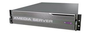
The Xmedia Server (XMS) is the central graphical asset management server for Vertigo Suite channel branding and playout systems. The Xmedia Server allows all branding assets to be ingested once, centrally archived, and automatically moved to the desired graphics device using rule-based publishing.
Figure 1-1. Xmedia Server - a central graphical asset management server
The main purpose of this configuration guide is to provide practical reference and procedural information on how to use the Xmedia Server Control Panel application to configure the Xmedia Server.
The following sections of this chapter provide general information about the Xmedia Server and its optional features:
•“About the Xmedia Server” on page 1-2
•“Xmedia Server’s standard and option features” on page 1-3
The next couple of chapters provide specific information about the Xmedia Server’s hardware, software, and network integration. Further chapters provide instructions for how to configure the Xmedia Server using the Xmedia Server Control Panel.
XMS Configuration Guide |
1-1 |

Introduction
About the Xmedia Server
The Xmedia Server (XMS) is the central graphical asset management server for Vertigo Suite channel branding and playout systems. Assets only need to be ingested once for them to be centrally archived on the Xmedia Server. These assets are then made available to all of the Vertigo Suite applications on the network, which allow you to create a wide range of graphics, including advanced, data-driven broadcast applications that link on-air graphics elements to live data feeds. The resulting graphic pages and their assets can then be automatically published to a range of graphics playout devices, including Imagestore, Intuition XG, and Vertigo XG devices.
The Xmedia Server offers benefits to larger broadcast systems that have multiple channels by sharing assets between channels without having to duplicate the assets. It also allows for a more dynamic handling of content and a more natural workflow because media creation, asset management, and asset distribution are conveniently linked by a common environment.
Besides its main use as a central asset repository and asset management/distribution system, the Xmedia Server integrates and supports the Vertigo Suite applications and other playout devices. The following list identifies other ways in which the Xmedia Server is used to support graphics creation and playout activities:
•Asset propagation: The Xmedia Server can be used in a hub and spoke distribution model in which assets can be created and propagated from a central hub to various spoke servers.
•Server replication: Two Xmedia Servers can be configured to offer full redundancy for near instant failover with no interruption in services, including on-air playout.
•Newsroom integration: The Xmedia Server can provide graphics assets to newsroom environments using the MOS protocol to integrate with the newsroom control system.
•User rights management: Using the Xmedia Server’s user rights management system, system administrators and workflow managers can restrict access to some of the system’s functionality and/or asset categories on a per-user basis.
•License management: The Xmedia Server stores and manages the software licenses that are required to operate each of the Vertigo Suite applications.
•Work Order Workflow: The Xmedia Server provides an optional work order workflow module that fully integrates into the Vertigo Suite. The work order workflow is used for requesting, completing, tracking and approving graphics work orders.
1-2 |
XMS Configuration Guide |

Introduction
Xmedia Server’s standard and option features
The Xmedia Server is a 2RU rackmount server with 2TB of RAID-1 storage and is factory configured to run Windows Server 2003 as its operating system. Additional software applications and services that are factory installed include:
•MICROSOFT SQL SERVER 2008: The Xmedia Server uses a Microsoft SQL Server database to store asset details, categories, work order processing data, publish processing data, and other relational information and data. See page 5-1 for more information.
•XMEDIA SERVER CONTROL PANEL: The Xmedia Server Control Panel is the user interface for configuring and controlling the Xmedia Server. See page 3-14 for more information.
•VERTIGOXMEDIA DATA SERVER: The Data Server is a service application that manages data coming from various feeds, provides live updates of data values when requested and distributes the data out to the appropriate recipients. See page 3-5 for more information.
•File Ingest Server: The File Ingest Server is a service responsible for automatically ingesting media into the Xmedia Server from a user-created ingest folder. The File Ingest Server is also responsible for issuing media conversion requests to the Transcode Server, which is the service responsible for transcoding media from one format to another. See page 3-13 for more information.
In addition to the Xmedia Server unit, the following options are also offered to enhance the capabilities of the Xmedia Server:
•“Work Order Management Option” on page 1-3
•“Xplorer - Media Asset Management application” on page 1-3
Work Order Management Option
The Xmedia Server provides an optional work order workflow module (VX-WOM) that fully integrates into the Vertigo Suite. The work order workflow is used for requesting, completing, tracking and approving graphics work orders. See “Work Order workflow configuration” on page 10-1 for more information on how to use the Xmedia Server Control Panel to create and configure the work order workflow module.
Xplorer - Media Asset Management application
The Vertigo Suite features the XPLORER application (VX-Xplorer), which is a graphical content management system for viewing and managing the asset and file contents of the Xmedia Server and the devices to which the XMS has published assets. See the XPLORER USER MANUAL for more information.
XMS Configuration Guide |
1-3 |

Introduction
1-4 |
XMS Configuration Guide |
2 XMS HARDWARE OVERVIEW
Physically, the Xmedia Server is a 2RU rackmount server that incorporates redundant fans, power, and ethernet ports, with 2 TB of RAID-1 storage. The Xmedia Server features easy frontal access to the storage drives, and a control panel featuring LEDs and buttons for system monitoring and operation. The rear panel also provides convenient access to two power supply modules, seven PCI expansion slots (video, audio, and graphics cards), and various I/O ports (USB, COM1, VGA, Ethernet...etc).
The following sections provide additional details regarding the Xmedia Server’s hardware:
•“Front panel components, LEDs and buttons” on page 2-2
•“Back panel components and connectors” on page 2-4
•“Mounting the Xmedia Server chassis in a rack” on page 2-5
 CAUTION
Xmedia Server devices should only be installed by trained personnel in a restricted access locations only. All health and safety regulations and precautions must be observed.
Chassis |
FORM: 2U rackmount chassis |
|
HEIGHT: 3.5” (89mm) |
|
WIDTH: 17.2” (437mm) |
|
DEPTH: 25.5” (648mm) |
|
|
Power consumption |
700W (1 + 1) Redundant AC-DC power supply. |
|
Maximum draw is a total of 700W. |
|
Note that the device’s electrical ratings are located on the |
|
plug-in power supply modules. |
|
|
Temperature |
Ambient temperature: 35°C |
|
Note: This shall be the maximum internal temperature within |
|
the rack in which the Xmedia Server unit is installed. |
|
|
 WARNING
To reduce the risk of electric shock, disconnect all power sources before servicing Xmedia Server devices.
XMS Configuration Guide |
2-1 |

XMS hardware overview
Front panel components, LEDs and buttons
Figure 2-1 demonstrates that the Xmedia Server’s front panel provides easy access to the SATA drives, a floppy drive, DVD-ROM, a front port panel (USB & serial) and a control panel featuring LEDs and buttons for system monitoring and operation.
Floppy drive |
Front Port Panel |
DVD-ROM |
Control Panel |
||
|
|
|
|
|
(LEDs & buttons) |
|
|
|
|
|
|
|
|
|
|
|
|
|
|
|
|
|
|
RAID
Drives
Figure 2-1. The Xmedia Server’s front panel components
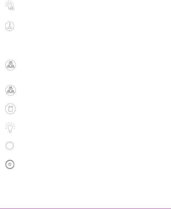
Figure 2-2 demonstrates that the control panel located on the front of the Xmedia Server chassis has six LEDs and two buttons. The table on page 2-3 describes the function of each LED and button, as well any corrective action you may need to take.
Figure 2-2. Xmedia Server chassis control panel LEDs and buttons
2-2 |
XMS Configuration Guide |
|
|
XMS hardware overview |
|
|
|
|
|
|
POWER FAIL |
Indicates a power supply module has failed. This should be accompanied |
|
|
|
by an audible alarm. A backup power supply module will take the load and |
|
|
|
keep the system running, but the failed module will need to be replaced. |
|
|
|
This LED should be off when the system is operating normally. |
|
|
|
|
|
|
OVERHEAT / FAN FAIL |
When this flashes, it indicates a fan failure. When it is constantly |
|
|
|
illuminated (solid on), it indicates an overheat condition, which may be |
|
|
|
caused by cables obstructing the airflow in the system or the ambient room |
|
|
|
temperature being too warm. Check the routing of cables and make sure |
|
|
|
that all fans are present and operating normally. You should also check to |
|
|
|
make sure that the chassis covers are installed properly. Finally, verify that |
|
|
|
the heatsinks are installed properly. This LED will remain flashing or on as |
|
|
|
long as the above mentioned conditions exist. |
|
|
|
|
|
|
NIC2 |
A flashing NIC2 LED indicates network activity on LAN2. |
|
|
|
|
|
|
NIC1 |
A flashing NIC1 LED indicates network activity on LAN2. |
|
|
|
|
|
|
HDD |
Indicates IDE channel activity. |
|
|
|
|
|
|
POWER (LED) |
Indicates that power is being supplied to the system’s power supply units. |
|
|
|
This LED should normally be illuminated when the system is in operation. |
|
|
|
|
|
|
RESET (BUTTON) |
The Reset button reboots the system. |
|
|
|
|
|
|
POWER (BUTTON) |
This is the main power button, which is used to apply or turn off the main |
|
|
|
system power. Turning off this button removes the main power, but keeps |
|
|
|
standby power supplied to the system. |
|
|
|
|
|
XMS Configuration Guide |
2-3 |
Loading...