


QuickStart Guide
NV920 Control System
and Accessories
Product Summary
Your shipment from Grass Valley contains an NV920 frame containing one or two NV920 system controllers and power supplies, power cords, and this Quick Start guide. Depending on your order options, the shipment might also include cables and peripheral devices. See Figure 1.
An NV920 system controller allows you to configure and operate routers, control panels, and other connected equipment. A complete NV920 control system includes several parts that work together:
•NV920 system controller(s).
•NV9000-SE Utilities configuration software.
•PCs running configuration or control software.
•Routers.
•Control panels (physical or virtual).
•Optionally, master control components.
•Optionally, automation, UMD, monitor walls, and other subsystems.
Control Systems
The NV920 is a member of Grass Valley’s NV9000 family of system controllers. In order of price and performance, the series includes these control systems:
•NV960
Each NV960 system controller is 2RU, has 2 disk drives, and 3 PCI expansion slots. Two of the expansion slots typically provide Ethernet connections. The remaining expansion slot can be used for other purposes such as connecting serial devices.
Several models of the NV960 are available.
•NV920
Each NV920 is 1RU and houses two system controllers. Each system controller has 2 disk drives, 3 Ethernet ports, and no expansion slots. However each NV920 does have an RS-485 port that supports one serial device.
Several models of the NV920 are available. as listed on this page.
•NV915
Each NV915 system controller is 1RU, has one disk drive, 2 Ethernet ports, and no expansion ports. One of the Ethernet port is available to support routers and control panels. (Older NV915s had compact flash and no disk drive.)
The NV960, NV920, and the NV915 run the same software. The NV920 is priced between the NV960 and the NV915.
A system controller is a device that (1) receives commands from control panel operators or from third-party systems, (2)
Figure 1. Package Contents
NV920
Power cords |
|
|
QuickStart Guide |
||
|
|
|
|
|
(this document) |
Software and
Documentation CD
dispatches instructions to routers, and (3) returns status information to the control panels or to automation.
The NV920 product line includes these items:
•NV920D. NV920 frame with dual controllers.
•NV920S. NV920 frame with a single controller.
•NV920-PRI. A primary NV920 system controller.
•NV920-SEC. A secondary NV920 system controller.
•NV920-FME. An NV920 frame only.
•NV920-FRU. A “field replacement unit,” that is, a spare system controller.
The NV920
The NV920 frame is a 1RU frame which contains a power supply having two removable power supply modules, and one or two removable NV920 system controllers. See Figure 2.
One controller is labeled ‘Primary’ and the other ‘Secondary’. These terms distinguish one from the other, but otherwise have no specific meaning.
The NV920 frame has two power supply modules for redundancy. In normal operation, both supplies operate in tandem, sharing the load. If one power supply module fails, the other immediately absorbs the full load.
If the NV920 frame has two system controllers, it is for redundancy. One of the system controllers is active; the other is stand-by. If the active system controller fails, the stand-by system controller takes over.
Product Number: QG0014-03 Revision: A0; Date: 11/26/14 |
1 |

NV920 Control System
Figure 2. NV920
Power LEDs |
Primary System Controller |
|
Secondary System Controller |
|||||
Front View |
|
|
|
|
|
|
|
|
|
|
|
|
|
|
|
||
|
|
|
|
|
|
|||
|
|
|
|
|
|
|
|
|
Rear View |
Power Failure Alarm Mute Button |
Connectors for Secondary System Controller |
Connectors for Primary System Controller |
PS 2 |
PS 1 |
|||||||
The power supplies are removable (replaceable) from the rear |
|
perform diagnostic and maintenance tasks using XP’s normal |
||||||||
of the frame. The system controllers are removable (replace- |
|
Windows desktop.) You can also use the USB ports to update |
||||||||
able) from the front of the frame. |
|
|
|
|
the system controller’s software. |
|
||||
If you have an NV920S (single controller) the empty second- |
|
The “EIA-485” connector (DE9) supports the control of one |
||||||||
ary bay will have a blank front plate. |
|
|
|
|
serial device. The port’s pinout is the same as that of a Moxa |
|||||
|
|
|
|
|
|
|
|
CP-118U. You can use a WC0137 “Y” cable to connect the two |
||
The System Controller |
|
|
|
|
|
|
system controllers of an NV920 to the device you are control- |
|||
At the rear of the NV920 frame are two identical sets of con- |
|
ling. The “Y” cable forms a redundant connection. |
||||||||
|
There are Tx and Rx status LEDs for the serial port that illumi- |
|||||||||
nectors, one for each system controller. See Figure 3. |
|
|||||||||
Among these are 3 Ethernet (RJ-45) connectors. Two support |
|
nate when the port is transmitting and receiving, respec- |
||||||||
|
tively. (Internally, the port is COM2. This designation might |
|||||||||
1G Ethernet. The third supports 100M Ethernet. The Ether- |
|
|||||||||
|
be important, for example, when you are using NV9000-SE |
|||||||||
net ports are otherwise identical. At least one must be used |
|
|||||||||
|
Utilities to configure routers that have serial connections.) |
|||||||||
for a panel and router network. One must be connected to |
|
|||||||||
|
There are also cooling fans at the rear of each system control- |
|||||||||
your “house network” for configuration and monitoring. |
|
|||||||||
Two USB ports and a VGA port allow you to connect a key- |
|
ler. The rear of the NV920 frame has grill openings that vent |
||||||||
|
the exhaust from the fans. |
|
|
|||||||
board, mouse, and monitor to the system controller. (The sys- |
|
|
|
|||||||
|
Each system controller is removable. At the left side at the |
|||||||||
tem controller runs Windows XP embedded, so you can |
|
|||||||||
|
|
|
|
|
|
|
|
front of the system controller is a latch. Turn the latch a quar- |
||
Figure 3. System Controller |
|
|
|
|
ter turn to lock the system controller in place. Turn the latch |
|||||
|
|
|
|
in the other direction to remove the system controller. |
||||||
Rear (Panel) View |
|
COM2 |
|
VGA |
|
|
|
|||
|
|
|
|
|
Use the handle of the system controller to pull it out of its bay |
|||||
|
|
|
|
|
||||||
|
|
|
|
|
|
|
|
|||
(or to carry it).
|
USB |
|
Front View |
Latch |
Handle |
|
|
|
|
LEDs |
Buttons |
2 |
|
|
The large button (backlit, white) at the right is labeled “Power Down to Remove.” It is important to power the system controller off before removing it. When the system controller is powered up, the 2 green LEDs (labeled +5V and +12V), the 3 status LEDs, and the 2 white buttons illuminate. When the system controller’s software finishes initializing, the alarm LED goes out.
There are 3 status LEDs in the middle of the front of the system controller:
•Healthy. This LED is green (on) when the system controller is running properly. If the NV920 frame has two system controllers, the health LED is normally on for both.
•Active. This LED is amber (yellow) when the system controller is the active controller. When the NV920 frame has
Product Number: QG0014-03 Revision: A0; Date: 11/26/14

NV920 Control System
two system controllers, the LED is on only for the one controller that is active.
•Alarm. This LED is normally off, but turns red when an alarm condition is present in the controller. It is possible for each controller in a dual-controller frame to show an alarm.
The ‘Force Active’ button (backlit, white) allows you to cause the stand-by system controller (in a dual-controller frame) to become the active controller. When the controller becomes active, its active LED turns on and the active LED of the other controller turns off.
For more information on control panels, obtain the appropriate control panel user’s guide from the Grass Valley website. Contact Grass Valley customer service for assistance.
Master Control
Master Control is a name given to an optional subsystem that allows operators to transition program output from one source to another with real-time effects such as cross-fades, keyer and logo overlays, squeezeback, and audio overs.
For more information, either visit the Grass Valley website or contact Grass Valley customer service.
Power Supplies
Both of the frame’s power supply modules accept from 100 to 240 VAC, 47–63 Hz, automatically sensing the line voltage and frequency.
The NV920 frame has two power LEDs. One LED, labeled ‘Power’ at the front of the frame, indicates the presence of power. The other power LED (‘PS Alarm’) is off under normal circumstances, but turns red and blinks when one of the power supplies is missing or faulty.
When one of the power supplies is removed (or fails), the frame emits an audible alarm (a continuous tone). The frame has a red button (at the rear) near the power supplies that turns off the alarm.
This QuickStart Guide
The purpose of this document is to guide you through the physical installation of the NV920 frame, the installation of configuration software, and the initial setup of the software so that you can build configurations and read from and write to your system controller(s).
NV9000-SE Utilities is the primary tool for configuration.
NV9000-SE Utilities
NV9000-SE Utilities is software that is required for the configuration and management of the NV920 control system. It is available on the SB0033 CD in this shipment.
After you have obtained NV9000-SE Utilities, you can install it on any PC.
Control Panels
Control panels allow operators to setup and execute “takes” (routes) between source devices and destination devices. Physical control panels are separate hardware units that connect to the system controller. Virtual control panels are software applications that emulate physical control panels and run on any PC (or Mac) connected, through Ethernet, to the system controller.
System Controller Redundancy
A redundant system includes 2 system controllers. If one system controller fails, the control system immediately switches to the other controller.
The two system controllers of a dual-controller NV920 communicate with each other through an internal Ethernet link.
The stand-by system controller queries the active system controller frequently through the internal link. If the query and response mechanism fails, the stand-by controller presumes that the active controller is no longer functioning properly and takes over the role of active controller.
Installation
Setting up the NV920 system controller requires several steps:
Part 1 Mount the NV920 in a rack, insert its power supplies, system controllers, and connect power.
Part 2 Make physical network and I/O connections.
Part 3 Install NV9000-SE Utilities software on your configuration PC(s).
Part 4 Perform initial setup in NV9000-SE Utilities.
Networks require an Ethernet switch and CAT5 Ethernet cable. (Grass Valley’s EC9415—a 24-port Ethernet switch—is suitable.)
Part 1: Mount the Controller and Connect Power
The 1RU NV920 frame fits in a standard 19″ (482.6 mm) rack. When placing the NV920 frame in your facility, keep in mind that the NV920 needs a minimum of 6″ (15cm) of unrestricted air flow at the front and rear for cooling and needs an adequate amount of space at the sides for air intake.
The NV920 frame (with power supplies and system controllers installed) extends 19.9″ toward the rear of the rack and projects about 1.2″ in front of the rack.
The removable power supply modules are about 10.5″ deep. So you will need about 12″ clearance at the rear to remove and insert power supply modules.
The NV920 frame is heavy and requires mounting hardware at the rear of the frame. See Figure 4.
Product Number: QG0014-03 Revision: A0; Date: 11/26/14 |
3 |
NV920 Control System
Follow these steps to mount the NV920:
1) Locate the mounting hardware attached to the side of the |
Figure 4. Frame Support |
NV920 frame. There are two metal parts for each side of |
|
the frame. Unscrew the metal parts from the frame. |
(front of unit) |
|
2)Referring to Figure 4, attach the two small parts (with the slot) to the posts at the rear of the frame at the height at which you will install the frame.
3)Reattach the two long parts to the frame so that they will extend into the slots of the small parts at the rear of the frame. Again, refer to Figure 4.
4)Now move the frame into position, with its support extensions sliding into the slots of the supports at the rear of the frame.
Attach the front of the frame to the front posts of the frame using appropriately sized screws.
5)Insert power supply module(s) and system controller(s).
6)Use the supplied power cords to connect power. The controller’s power supplies accept 100–240VAC, 47–63 Hz).
UL caution: to reduce the risk of electric shock, plug each power supply cord into separate branch circuits employing separate service grounds. Redundant power connections, of course, provides additional protection against failure.
If the NV920 frame emits an alarm tone, press the red button next to the power supplies at the rear of the frame.
Caution: If you disconnect power without first shutting down the system controllers, you risk corrupting system data. Before disconnecting power, press the ‘Power Down to Remove’ button of each system controller of the frame. Wait for the system controllers’ LEDs to turn off. Then disconnect power.
Part 2: Make Connections to the System Controller
The additional units that compose the NV9000 control sys- tem—PCs, control panels, routers —communicate through the active system controller. The system controller uses Ethernet to communicate
Attach to rear rack posts.
with system components.
Each of the NV920’s ports has a unique IP address, fixed internally. The IP addresses depend on whether the system controller is stand-alone or redundant:
|
Single |
Redundant |
Redundant |
Port |
Controller |
Controller 1 |
Controller 2 |
|
|
|
|
NVNET1 |
192.168.1.1 |
192.168.1.1 |
192.168.1.2 |
|
|
|
|
NVNET2 |
192.168.2.1 |
192.168.2.1 |
192.168.2.2 |
|
|
|
|
NVNET3 |
192.168.3.1 |
192.168.3.1 |
192.168.3.2 |
|
|
|
|
You may change any of these addresses to match your facility’s networks.
Example: Two Networks for Panels and Routers
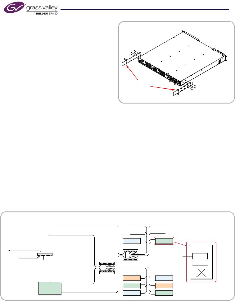
Figure 5, below, diagrams a redundant system that uses two Ethernet ports for panels and routers and the third port for configuration and monitoring. (If your system has a single system controller, please disregard controller 2 in the diagram and any connections to it.)
Figure 5. Connections for a Redundant NV920 — Two Panel and Router Networks
|
|
NVNET 1 |
|
|
|
|
NV920 |
Tally |
|
Panel |
|
|
|
|
|||
|
|
|
|
|
|
|
Controller 1 |
NVNET 2 |
|
|
|
|
Router |
|
Tally |
||
|
|
|
|||
|
|
|
|
|
|
|
NVNET 3 |
|
Panel |
Panel |
Router |
|
|
|
and |
||
|
|
|
|
|
|
“House Net” |
|
|
Router |
|
NV Router |
|
|
Networks |
|
||
|
|
|
|
|
|
Config. |
|
|
|
|
Prim. Ctrl. |
|
|
|
|
|
|
PCs, |
NV9000 |
|
|
|
Sec. Ctrl. |
GUIs |
GUIs |
|
|
|
|
|
NVNET 3 |
|
|
Tally |
Panel |
|
NV920 |
NVNET 2 |
|
Router |
Tally |
|
Controller 2 |
|
|
Panel |
Router |
|
|
NVNET 1 |
|
||
|
|
|
|
|
4 |
Product Number: QG0014-03 Revision: A0; Date: 11/26/14 |
 Loading...