


 Loading...
User’s Guide
3922 496 31761 May 2011 v1.0
|
Power On |
|
|
Camera |
On Air |
Base |
Test Connected |
Communication |
Mains |
Station |
|
|
Ready |
Camera |
LDK 4410 + LDK 5420
3G Fiber Transmission System

Copyright
Copyright Grass Valley Nederland B.V. 2011. Copying of this document and giving it to others, and the use or communication of the contents thereof, are forbidden without express authority. Offenders are liable to the payment of damages. All rights are reserved in the event of the grant of a patent or the registration of a utility model or design. Liable to technical alterations in the course of further development.
Trademarks
Grass Valley is a trademark of Grass Valley, Inc. All other tradenames referenced are service marks, trademarks, or registered trademarks of their respective companies.
Website
Visit the Grass Valley public website to download the latest user’s guide updates and additional information about your broadcast product:
www.grassvalley.com

Table of contents
Chapter 1 – Introduction
1.1 Welcome. . . . . . . . . . . . . . . . . . . . . . . . . . . . . . . . . . . . . . . . . . . . . . . . . . . . . . . . . . . . 11
1.1.1 About this manual . . . . . . . . . . . . . . . . . . . . . . . . . . . . . . . . . . . . . . . . . . . . . . . 11 1.1.2 Related documents . . . . . . . . . . . . . . . . . . . . . . . . . . . . . . . . . . . . . . . . . . . . . . 11
1.2 System overview . . . . . . . . . . . . . . . . . . . . . . . . . . . . . . . . . . . . . . . . . . . . . . . . . . . . . 11
1.2.1 Transmission . . . . . . . . . . . . . . . . . . . . . . . . . . . . . . . . . . . . . . . . . . . . . . . . . . . 11 1.2.2 Dockable adapter . . . . . . . . . . . . . . . . . . . . . . . . . . . . . . . . . . . . . . . . . . . . . . . . 12 1.2.3 Base station . . . . . . . . . . . . . . . . . . . . . . . . . . . . . . . . . . . . . . . . . . . . . . . . . . . . 12 1.2.4 Operational controls. . . . . . . . . . . . . . . . . . . . . . . . . . . . . . . . . . . . . . . . . . . . . . 12 1.2.5 Intercom . . . . . . . . . . . . . . . . . . . . . . . . . . . . . . . . . . . . . . . . . . . . . . . . . . . . . . 12
1.3 Main features . . . . . . . . . . . . . . . . . . . . . . . . . . . . . . . . . . . . . . . . . . . . . . . . . . . . . . . . 13
Chapter 2 – Base station
2.1 Installation . . . . . . . . . . . . . . . . . . . . . . . . . . . . . . . . . . . . . . . . . . . . . . . . . . . . . . . . . . 15
2.1.1 Control bus . . . . . . . . . . . . . . . . . . . . . . . . . . . . . . . . . . . . . . . . . . . . . . . . . . . . 15 2.1.2 Intercom cabling . . . . . . . . . . . . . . . . . . . . . . . . . . . . . . . . . . . . . . . . . . . . . . . . 15 2.1.3 Studio signalling . . . . . . . . . . . . . . . . . . . . . . . . . . . . . . . . . . . . . . . . . . . . . . . . . 16 2.1.4 External audio level control . . . . . . . . . . . . . . . . . . . . . . . . . . . . . . . . . . . . . . . . 21 2.1.5 Private data . . . . . . . . . . . . . . . . . . . . . . . . . . . . . . . . . . . . . . . . . . . . . . . . . . . . 21
2.2 Base station menu . . . . . . . . . . . . . . . . . . . . . . . . . . . . . . . . . . . . . . . . . . . . . . . . . . . . 22
2.2.1 Using the rotary/push button . . . . . . . . . . . . . . . . . . . . . . . . . . . . . . . . . . . . . . . 22 2.2.2 Using the OCP . . . . . . . . . . . . . . . . . . . . . . . . . . . . . . . . . . . . . . . . . . . . . . . . . . 23 2.2.3 Menu navigation . . . . . . . . . . . . . . . . . . . . . . . . . . . . . . . . . . . . . . . . . . . . . . . . 24
2.3 Intercom setup . . . . . . . . . . . . . . . . . . . . . . . . . . . . . . . . . . . . . . . . . . . . . . . . . . . . . . . 27
2.3.1 Studio interface setup . . . . . . . . . . . . . . . . . . . . . . . . . . . . . . . . . . . . . . . . . . . . 27
2.4 Reference and timing set up . . . . . . . . . . . . . . . . . . . . . . . . . . . . . . . . . . . . . . . . . . . . 28
2.4.1 Basic signal processing . . . . . . . . . . . . . . . . . . . . . . . . . . . . . . . . . . . . . . . . . . . 28 2.4.2 Adjustment procedure for HD timing . . . . . . . . . . . . . . . . . . . . . . . . . . . . . . . . 28 2.4.3 Adjustment procedure for SD timing . . . . . . . . . . . . . . . . . . . . . . . . . . . . . . . . . 29
Chapter 3 – Camera adapter
3.1 Mounting . . . . . . . . . . . . . . . . . . . . . . . . . . . . . . . . . . . . . . . . . . . . . . . . . . . . . . . . . . . 31
3.1.1 General . . . . . . . . . . . . . . . . . . . . . . . . . . . . . . . . . . . . . . . . . . . . . . . . . . . . . . . 31 3.1.2 Detaching. . . . . . . . . . . . . . . . . . . . . . . . . . . . . . . . . . . . . . . . . . . . . . . . . . . . . . 31 3.1.3 Attaching . . . . . . . . . . . . . . . . . . . . . . . . . . . . . . . . . . . . . . . . . . . . . . . . . . . . . . 32 3.1.4 Adjusting the shoulder pad . . . . . . . . . . . . . . . . . . . . . . . . . . . . . . . . . . . . . . . . 32
3.2 Controls and indicators . . . . . . . . . . . . . . . . . . . . . . . . . . . . . . . . . . . . . . . . . . . . . . . . 33
3.2.1 Overview . . . . . . . . . . . . . . . . . . . . . . . . . . . . . . . . . . . . . . . . . . . . . . . . . . . . . . 33 3.2.2 Power . . . . . . . . . . . . . . . . . . . . . . . . . . . . . . . . . . . . . . . . . . . . . . . . . . . . . . . . 33 3.2.3 Selecting monitoring signals . . . . . . . . . . . . . . . . . . . . . . . . . . . . . . . . . . . . . . . 34 3.2.4 Using audio . . . . . . . . . . . . . . . . . . . . . . . . . . . . . . . . . . . . . . . . . . . . . . . . . . . . 34 3.2.5 Intercom . . . . . . . . . . . . . . . . . . . . . . . . . . . . . . . . . . . . . . . . . . . . . . . . . . . . . . 36 3.2.6 Communication . . . . . . . . . . . . . . . . . . . . . . . . . . . . . . . . . . . . . . . . . . . . . . . . . 37
LDK 4410 + LDK 5420 3G Fiber Transmission System User’s Guide (v1.0) |
3 |

Chapter 4 – Transmission
4.1 Base station indicators . . . . . . . . . . . . . . . . . . . . . . . . . . . . . . . . . . . . . . . . . . . . . . . . 39 4.2 Transmission diagnostics . . . . . . . . . . . . . . . . . . . . . . . . . . . . . . . . . . . . . . . . . . . . . . 41
4.2.1 Monitoring transmission . . . . . . . . . . . . . . . . . . . . . . . . . . . . . . . . . . . . . . . . . . 41 4.2.2 Sync/encoder HD board diagnostics . . . . . . . . . . . . . . . . . . . . . . . . . . . . . . . . . 41
4.3 Board locations . . . . . . . . . . . . . . . . . . . . . . . . . . . . . . . . . . . . . . . . . . . . . . . . . . . . . . 42
4.3.1 Base station board locations . . . . . . . . . . . . . . . . . . . . . . . . . . . . . . . . . . . . . . . 42 4.3.2 Camera adapter board locations . . . . . . . . . . . . . . . . . . . . . . . . . . . . . . . . . . . . 43
4.4 Replacements. . . . . . . . . . . . . . . . . . . . . . . . . . . . . . . . . . . . . . . . . . . . . . . . . . . . . . . . 43
4.4.1 Replacing base station fuses . . . . . . . . . . . . . . . . . . . . . . . . . . . . . . . . . . . . . . . 43 4.4.2 Replacing base station power supply unit . . . . . . . . . . . . . . . . . . . . . . . . . . . . . 45 4.4.3 Replacing base station air filter . . . . . . . . . . . . . . . . . . . . . . . . . . . . . . . . . . . . . 46
Chapter 5 – Menus
5.1 Base station menu . . . . . . . . . . . . . . . . . . . . . . . . . . . . . . . . . . . . . . . . . . . . . . . . . . . . 47
5.1.1 Top level. . . . . . . . . . . . . . . . . . . . . . . . . . . . . . . . . . . . . . . . . . . . . . . . . . . . . . . 47 5.1.2 Video menu . . . . . . . . . . . . . . . . . . . . . . . . . . . . . . . . . . . . . . . . . . . . . . . . . . . . 48 5.1.3 Monitoring menu . . . . . . . . . . . . . . . . . . . . . . . . . . . . . . . . . . . . . . . . . . . . . . . . 49 5.1.4 Audio/intercom menu . . . . . . . . . . . . . . . . . . . . . . . . . . . . . . . . . . . . . . . . . . . . 50 5.1.5 SDTV menu . . . . . . . . . . . . . . . . . . . . . . . . . . . . . . . . . . . . . . . . . . . . . . . . . . . . 51 5.1.6 System menu. . . . . . . . . . . . . . . . . . . . . . . . . . . . . . . . . . . . . . . . . . . . . . . . . . . 52 5.1.7 Files menu . . . . . . . . . . . . . . . . . . . . . . . . . . . . . . . . . . . . . . . . . . . . . . . . . . . . . 54 5.1.8 Diagnostics menu . . . . . . . . . . . . . . . . . . . . . . . . . . . . . . . . . . . . . . . . . . . . . . . 55
5.2 Camera adapter menu. . . . . . . . . . . . . . . . . . . . . . . . . . . . . . . . . . . . . . . . . . . . . . . . . 58
5.2.1 Install menu . . . . . . . . . . . . . . . . . . . . . . . . . . . . . . . . . . . . . . . . . . . . . . . . . . . . 58 5.2.2 Diagnostics menu . . . . . . . . . . . . . . . . . . . . . . . . . . . . . . . . . . . . . . . . . . . . . . . 62
Chapter 6 – Connectors
6.1 LDK 4410 3G Fiber base station connectors . . . . . . . . . . . . . . . . . . . . . . . . . . . . . . . 65
6.1.1 Connector locations . . . . . . . . . . . . . . . . . . . . . . . . . . . . . . . . . . . . . . . . . . . . . . 65 6.1.2 Power supply unit . . . . . . . . . . . . . . . . . . . . . . . . . . . . . . . . . . . . . . . . . . . . . . . 65 6.1.3 Communication module. . . . . . . . . . . . . . . . . . . . . . . . . . . . . . . . . . . . . . . . . . . 66 6.1.4 BNC connector board. . . . . . . . . . . . . . . . . . . . . . . . . . . . . . . . . . . . . . . . . . . . . 68 6.1.5 Transmission module. . . . . . . . . . . . . . . . . . . . . . . . . . . . . . . . . . . . . . . . . . . . . 71
6.2 LDK 5420 3G Fiber camera adapter connectors . . . . . . . . . . . . . . . . . . . . . . . . . . . . 72
6.2.1 Connector locations back panel . . . . . . . . . . . . . . . . . . . . . . . . . . . . . . . . . . . . . 72 6.2.2 Connector locations side panels . . . . . . . . . . . . . . . . . . . . . . . . . . . . . . . . . . . . 74
Chapter 7 – Specifications
7.1 LDK 4400 3G Fiber base station specifications . . . . . . . . . . . . . . . . . . . . . . . . . . . . . 77
7.1.1 Technical specifications . . . . . . . . . . . . . . . . . . . . . . . . . . . . . . . . . . . . . . . . . . . 77 7.1.2 LDK 4531/30 High Quality SD module. . . . . . . . . . . . . . . . . . . . . . . . . . . . . . . . 78 7.1.3 Dimensions . . . . . . . . . . . . . . . . . . . . . . . . . . . . . . . . . . . . . . . . . . . . . . . . . . . . 79
7.2 LDK 5420 3G camera adapter specifications . . . . . . . . . . . . . . . . . . . . . . . . . . . . . . . 80
7.2.1 Technical specifications . . . . . . . . . . . . . . . . . . . . . . . . . . . . . . . . . . . . . . . . . . . 80 7.2.2 Dimensions . . . . . . . . . . . . . . . . . . . . . . . . . . . . . . . . . . . . . . . . . . . . . . . . . . . . 81
4 |
LDK 4410 + LDK 5420 3G Fiber Transmission System User’s Guide (v1.0) |

End-of-life product recycling
Grass Valley’s innovation and excellence in product design also extends to the programs we’ve established to manage the recycling of our products. Grass Valley has developed a comprehensive end-of-life product take back program for recycle or disposal of end-of-life products. Our program meets the requirements of the European Union’s WEEE Directive and in the United States from the Environmental Protection Agency, individual state or local agencies.
Grass Valley’s end-of-life product take back program assures proper disposal by use of Best Available Technology. This program accepts any Grass Valley branded equipment. Upon request, a Certificate of Recycling or a Certificate of Destruction, depending on the ultimate disposition of the product, can be sent to the requester. Grass Valley will be responsible for all costs associated with recycling and disposal, including freight, however you are responsible for the removal of the equipment from your facility and packing the equipment ready for pickup.
For further information on the Grass Valley product take back system please contact Grass Valley at + 800 80 80 20 20 or +33 1 48 25 20 20 from most other countries. In the US and Canada please call 800-547-8949 or 530- 478-4148. Ask to be connected to the EH&S Department. In addition, information concerning Grass Valley’s environmental policy can be found at:
www.grassvalley.com/about/environmental-policy
Packing/unpacking
Inspect the shipping container for evidence of damage immediately after receipt. If the shipping container or cushioning material is damaged, it should be kept until the contents of the shipment have been checked for completeness and the units have been checked mechanically and electrically. The shipping container should be placed upright and opened from the top. Remove the cushioning material and lift out the contents. The contents of the shipment should be checked against the packing list. If the contents are incomplete, if there is mechanical damage or defect, or if the units do not perform correctly when unpacked, notify your sales or service centre within eight days. If the shipping container shows signs of damage or stress, notify the carrier as well.
If a unit is being returned to for servicing, try to use the containers and materials of the original packaging. Attach a tag indicating the type of service required, return address, model number, full serial number and the return number which will be supplied by your service centre. If the original packing can no longer be used, the following general instructions should be used for repacking with commercially available materials:
1.Wrap unit in heavy paper or plastic.
2.Use strong shipping container.
3.Use a layer of shock-absorbing material around all sides of the unit to provide firm cushioning and prevent movement inside container.
4.Seal shipping container securely.
5.Mark shipping container FRAGILE to ensure careful handling.
LDK 4410 + LDK 5420 3G Fiber Transmission System User’s Guide (v1.0) |
5 |

Declaration of conformity
We, Grass Valley Nederland B.V., Kapittelweg 10, 4827 HG Breda, The Netherlands, declare under our sole responsibility that this product is in compliance with the following standards:
–EN60065 Safety
–EN55103-1:2009 EMC (Emission) for the following environments:
(E1) Residential;
(E2) Commercial and light industrial;
(E3) Urban outdoors;
(E4) Controlled EMC environment, and the rural outdoors environment.
–The average half-cycle r.m.s. inrush currents for this product are:
-16 A (on intial switch-on);
-11 A (after a supply interruption of 5 s).
–EN55103-2 EMC (Immunity)
following the provisions of:
–the EMC Directive 2004/108/EC
–the Low Voltage Directive 2006/95/EC
FCC Class A Statement
This product generates, uses, and can radiate radio frequency energy and if not installed and used in accordance with the instructions, may cause interference to radio communications.
It has been tested and found to comply with the limits for a class A digital device pursuant to part 15 of the FCC rules, which are designed to provide reasonable protection against such interference when operated in a commercial environment.
Operation of this product in a residential area is likely to cause interference in which case the user at his own expense will be required to take whatever measures may be required to correct the interference.
6 |
LDK 4410 + LDK 5420 3G Fiber Transmission System User’s Guide (v1.0) |

Important information
Read these instructions carefully and retain them for future reference.
During installation and operation of this equipment, local building safety and fire protection standards must be observed.
Before connecting the equipment to the power supply of the installation, verify the proper functioning of the protective earth lead.
Whenever it is likely that safe operation is impaired, the apparatus must be made inoperative and secured against any unintended operation. The appropriate servicing authority must then be informed. For example, safety is likely to be impaired if the apparatus fails to perform the intended function or shows visible damage.
Any changes or modifications not expressly approved in this manual could void your authority to operate this equipment.
Cautions and Warnings
Read and comply with the warning and caution notices that appear in the manual.
–Warnings indicate danger that requires correct procedures or practices to prevent death or injury to personnel.
–Cautions indicate procedures or practices that should be followed to prevent damage or destruction to equipment or property.
Warnings
To prevent fire or shock hazard, do not expose the unit to rain or moisture.
To avoid electrical shock, do not remove covers or panels. Refer servicing to qualified personnel only.
In case of an emergency ensure that the power is disconnected.
Use only fuses of the type and rating specified.
Connect the product only to a power source with the specified voltage rating.
The base station must always be connected to protective earth. Do not interrupt the protection conductor inside or outside the unit. Do not disconnect the protective earth terminal. Intentional interruption is prohibited and is likely to make the unit dangerous.
To prevent risk of overheating, ventilate the units correctly.
For safety reasons the base station must be mounted in a 19-inch rack which has safety covers according to IEC65. When two base stations are mounted above each other, the minimum distance between them must be 50 mm or the rack must be force-air cooled.
LDK 4410 + LDK 5420 3G Fiber Transmission System User’s Guide (v1.0) |
7 |

Fiber-optic transmission units
CLASS 1
LASER PRODUCT
LASER KLASSE 1
PRODUKT
Laser safety statement (Europe)
Fiber-optic transmission units are classified as a "CLASS 1 Laser Product" according to EN 60825-1, Safety of Laser products. Class 1 laser products are considered safe and do not result in biological hazard if used according to the instructions.
Laser safety statement (US)
Fiber-optic transmission units are classified as a "CLASS 1 Laser Product" according to 21CFR 1040.10 of the US Food and Drug Administration (FDA) Center for Devices and Radiological Health.
Use of controls, adjustments or performance of procedures other than those specified herein may result in hazardous radiation exposure.
To ensure proper use of this product, please read this instruction manual carefully and retain for future reference. Should the unit ever require maintenance, contact an authorized service location.
Fiber-optic cable precautions
Fiber-optic cables and connectors are easily damaged; take the following percautions into account:
–Do not bend the cable beyond the minimum permissible bend range specified for the cable.
–Avoid kinks in the cable.
–Avoid subjecting the cable to a high tension force (even momentarily).
–Do not twist the cable when connecting it to equipment.
–Insert connectors straight and fully into their corresponding sockets.
–In fiber-optic cable systems always put the dust caps on cable and panel connectors immediately after disconnecting a cable. Keep the dust caps clean.
8 |
LDK 4410 + LDK 5420 3G Fiber Transmission System User’s Guide (v1.0) |

Cleaning fiber-optic connectors
WARNING
Never clean an optical connector attached to a fiber that is carrying light.
Particles of foreign matter on the tip of a ferrule can have a disabling effect on fiber-optic transmission. Fiber-optic connectors need to be cleaned every time they are mated and unmated; it is essential that fiber-optic users develop the necessary discipline to always clean the connectors before they are mated.
Use a commerially available cleaning kit specifically designed for fiber-optic connectors and follow the manufacturer's instructions carefully.
•The connector sections to be cleaned include the tips and sides of ferrules, the interior walls of alignment sleeves, and the interior and exterior of connector shells.
•For plugs, the interior surfaces of alignment sleeves and the tips of ferrules are to be cleaned with a cleaning stick treated with the appropriate fluid. (Cleaning sticks with a slender design are available that allow alignment sleeves to be cleaned without having to detach them.)
•For jacks, it is important to clean both the tips and sides of the completely protruding ferrules.
•Both the male and female connector shells tend to attract dust and metal particles, so it is important to clean both the insides and outsides.
•The fiber end face and ferrule must be absolutely clean before it is inserted into a transmitter or receiver.
•Mate the connector immediately! Don't let the connector lie around and collect dust before mating.
•Air can be used to remove lint or loose dust from the port of a transmitter or receiver to be mated with the connector. Never insert any liquid into the ports.
LDK 4410 + LDK 5420 3G Fiber Transmission System User’s Guide (v1.0) |
9 |

Base station earthing
The rear of the base station power supply unit has two separate screw terminals for protective earth  (PE) and video earth
  (VE). These are normally connected by a metal strap.
Metal strap
PE VE
The protective earth terminal is internally connected to the protective earth conductor of the power cable. In normal circumstances the connection between the protective earth and the video earth should not be broken. If required, the central earth connection wire of the studio can be connected to terminal PE in accordance with VDE regulation 0800/part2.
Only if the studio (or OB van) is equipped with separate protective and video earth systems may the metal strap be removed. Under these circumstances the video earth terminal must be connected to the central functional earth potential (video earth) of the studio. This earth potential should have functional protective and noiseless earth (FPE) qualities as stated in the VDE regulation 0800/part2. A low impedance interconnection of both earth conductors must be provided at the central studio earthing point.
Mains lead wiring for UK users
The wires in the mains lead are colored in accordance with the following code:
GREEN and YELLOWEARTH
BLUENEUTRAL
BROWNLIVE
As the colors of the wires in the mains lead of this apparatus may not correspond with the colored markings identifying the terminals in your plug proceed as follows:
•The wire colored GREEN AND YELLOW must be connected to the terminal on the plug
marked with the letter E or by the safety earth symbol  or colored GREEN or GREEN AND YELLOW.
•The wire colored BROWN must be connected to the terminal marked with the letter L or colored RED.
•The wire colored BLUE must be connected to the terminal marked with the letter N or colored BLACK.
Ensure that your equipment is connected correctly - if you are in any doubt consult a qualified electrician.
10 |
LDK 4410 + LDK 5420 3G Fiber Transmission System User’s Guide (v1.0) |
Chapter 1 - Introduction
Chapter 1
Introduction
1.1Welcome
The 3G Fiber Transmission System is a reliable and robust transmission system that uses advanced digital technology to transport video, control and many other signals from your HD camera head to your studio or OB van and vice versa.
1.1.1 About this manual
The purpose of this manual is to present a detailed description of how to install and operate the 3G Fiber Transmission System. It provides the information necessary to use the system in different configurations.
1.1.2 Related documents
Before proceeding, check the Grass valley website at www.grassvalley.com for the latest version of this user’s guide and additional information:
•Online versions of documentation; updated versions of user’s guides, data sheets, brochures, application notes in pdf-format are available for download.
•Software downloads; camera software updates, release notes and installation instructions are available for download.
1.2System overview
1.2.1 Transmission
Grass Valley’s latest 3G Fiber Transmission System is based on digital transmission and a new, robust power system. The transmission system consists of a dockable camera adapter that fits on Grass Valley HD camera heads and a base station that takes care of power, signal transport and connection to your studio or OB van.
The 3G Fiber Transmission System is the perfect interface between your HD camera and the rest of your system. The heavy-duty base station provides many features in a compact package while the camera adapter provides maximum freedom of movement.
LDK 4410 + LDK 5420 3G Fiber Transmission System User’s Guide (v1.0) |
11 |

Chapter 1 - Introduction
3G Fiber transmission offers video transmission and remote control of cameras up to a distance of 4,000 m (13,120 ft), using hybrid fiber cables.
Transmission quality can be precisely monitored before and during operation right from the OCP 400 operational control panel.
1.2.2 Dockable adapter
The dockable principle allows a choice of transmission and thus the greatest flexibility and cost-effective solutions in multiple applications.
1.2.3 Base station
The base station is only 2U high yet offers full broadcast functionality and quality. The low height means that rack space is saved. Its low power consumption and efficient internal cooling eliminate the need for space between adjacent units. Sliding rails are additionally available for easy access to the back panel. The wings on either side of the back panel protect all connectors from damage, including the Fiber connector. The Fiber connector itself can easily be mounted at different angles to suit all mounting requirements.
1.2.4 Operational controls
You can access the base station menu, which contains all operational settings, from an Operational Control Panel. In addition to the operational menu, the installation and service menus can be activated from the base station by pressing a switch behind the front panel. The base station is compatible with all existing control system components.
An OCP 400 operational control panel can be connected directly to the base station using a cross-over Ethernet cable.
Full camera control is provided via a C2IP Ethernet-based control network.
1.2.5 Intercom
The communication facilities provide for two-wire or four-wire high quality intercom signals.
12 |
LDK 4410 + LDK 5420 3G Fiber Transmission System User’s Guide (v1.0) |

Chapter 1 - Introduction
1.3Main features
•The 3G Fiber Transmission System offers flexible and multiple audio and video connectivity at the base station.
•Allows video transmission, power and control of cameras up to a distance of 4,000 m (13,120 ft) , using hybrid Fiber cables.
•Transmission of 1080p50/59.94, 1080i50/59.94, 720p50/59.94 and many psf HD video formats.
•Transports the following digital signals from camera to base station: main video signal, four audio channels (including embedded digital audio), two intercom channels, control and private data.
•Transports the following digital signals from base station to camera: power, two external HD video channels, teleprompter signal, three intercom channels, control and private data.
•Full camera control via Grass Valley’s C2IP Ethernet-based control network. Compatible with Grass Valley’s Fusion product line for seamless integration with other Grass Valley broadcast products.
•Two-wire or four-wire intercom compatible with international standards.
•The adapter has a compact and ergonomic design and is dockable with all Grass Valley HD cameras.
•All operational controls within easy reach at the back panel of the camera adapter.
•The swiveling Fiber connector on the camera adapter provides a maximum of freedom and moveability for the operator.
•Designed to fit onto the new Grass Valley Reflex SuperXpander: the hot shoe connection enables swift and easy coupling with the SuperXpander without the need for flying leads or other cabling.
•Base station built in a compact 2U high 19-inch rack housing.
•Teleprompter, color bar, HD-SDI outputs standard on board.
•The digital transmission backbone and power module meet the most demanding broadcasting needs.
•Heavy-duty design with a new base station power unit with low power consumption, ideal for OB vans.
•Both HD and simultaneous high-quality SD outputs (optional) are available.
LDK 4410 + LDK 5420 3G Fiber Transmission System User’s Guide (v1.0) |
13 |

Chapter 1 - Introduction
14 |
LDK 4410 + LDK 5420 3G Fiber Transmission System User’s Guide (v1.0) |

Chapter 2 - Base station
Chapter 2
Base station
2.1Installation
2.1.1 Control bus
The base station is connected to the control network hub or router via an Ethernet cable (straight-through, not cross-over). An OCP (Operational Control Panel) and, if required an MCP (Master Control Panel), are also connected to the Ethernet network via a hub or router. An OCP can also be connected directly to the base station using a cross-over Ethernet cable.
The IP address and other options for the Ethernet connection can be set up in the basestation system menu. These items can also be set up remotely using a network configuration tool such as Grass Valley’s SiteConfig.
Note
By default, the Ethernet connection is set up for automatic IP configuration.
2.1.2Intercom cabling
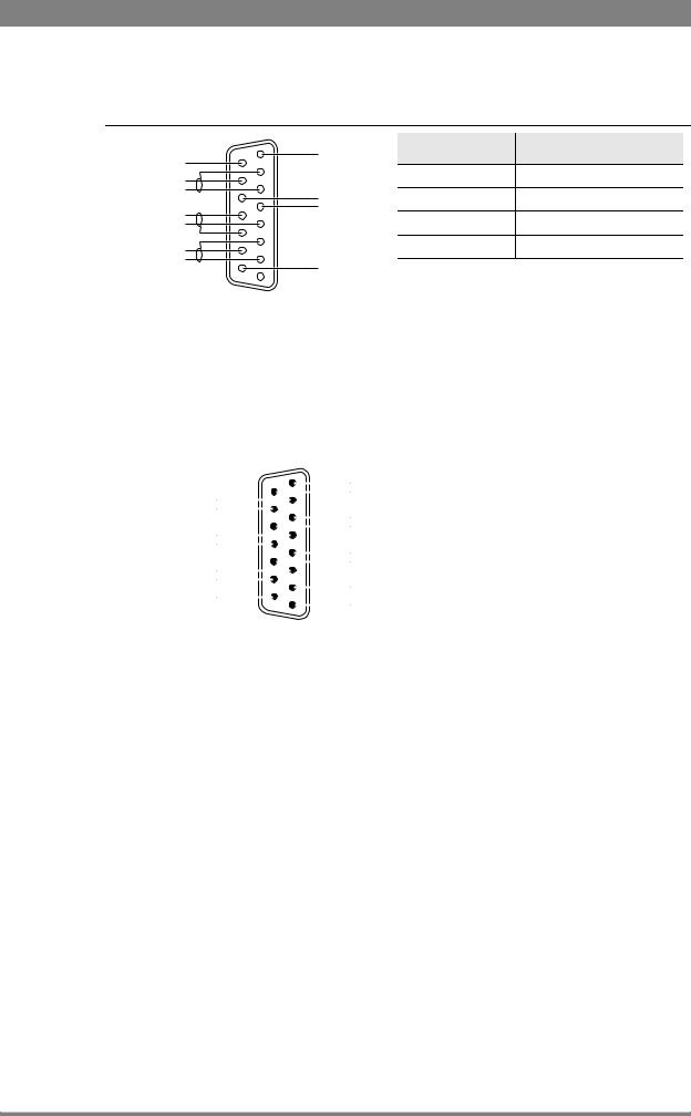
Connect the studio intercom system to the rear of the base station. The wiring of the panel connector is shown below for two-wire and four-wire systems.
Two-wire systems
|
|
Function |
Value |
|
8 |
Housing |
|
Housing |
15 |
Signal level |
0 dBu (RMS) |
|
|||
|
|
||
Prod |
- |
Load impedance |
200 |
|
+ |
||
|
- |
Eng in/out |
|
|
+ |
Voltage level |
max. 40 VDC |
|
|
- Prod in/out
9 +
+
1
LDK 4410 + LDK 5420 3G Fiber Transmission System User’s Guide (v1.0) |
15 |
Chapter 2 - Base station
Four-wire systems
|
8 |
Housing |
Function |
Value |
Housing |
15 |
|
|
|
|
|
Output signal level |
+6 or 0 dBu (RMS) selectable |
|
Prog in ret |
|
|
||
|
|
|
|
|
Prog in |
- |
Eng in/out |
Output impedance |
max. 50 symmetrical |
|
||||
Eng in ret |
+ |
Input signal level |
+6 or 0 dBu (RMS) selectable |
|
Eng in |
|
|
||
Prod in ret |
|
|
Impedance |
min. 9 k symmetrical |
Prod in |
- |
Prod in/out |
|
|
|
|
|
9 +
+
1
2.1.3 Studio signalling
Connect the studio signalling system to the rear of the base station. The wiring of the signalling connector is shown below:
Call out send Call out return
On Air send On Air return
Audio 1 level Audio 2 level
GND
1
9
15
8
Preview out send Preview out return
ISO in send
ISO in return
Call in send
Call in return
5 V
Housing
There are several connection methods for the ISO (On Air Yellow), On Air and Call signalling functions: dry contact, common ground, voltage level and open circuit/voltage level.
A selection in the SYSTEM > SIGNALLING menu allows you to make the activity state of the function (Active or Inactive) correspond to a particular input signal. There are two leads for each connection - Send and Return.
Signalling function |
Send pin |
Return pin |
|
|
|
ISO |
3 |
11 |
|
|
|
On Air |
4 |
12 |
|
|
|
Call |
2 |
10 |
|
|
|
16 |
LDK 4410 + LDK 5420 3G Fiber Transmission System User’s Guide (v1.0) |

Chapter 2 - Base station
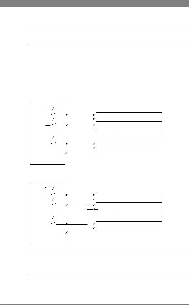
Dry contact
|
ISO 1a |
|
ISO in ext. send (pin 3) |
External ISO signalling |
ISO 1b |
(dry contact) |
ISO in ext. return (pin 11) |
|
|
|
On-Air (Tally) 1a |
|
On-Air in ext. (pin 4) |
External On-Air signalling |
On-Air (Tally) 1b |
(dry contact) |
On-Air in ext. return (pin 12) |
|
|
|
Call 1a |
|
Call in ext. (pin 5) |
External Call signalling |
Call 1b |
(dry contact) |
Call in ext. return (pin 13) |
|
Note
A common return (not ground!) can be used for all three functions (ISO, On Air and Call)
If a contact is closed, the corresponding function is Active or Inactive, depending on the selection the SYSTEM > SIGNALLING menu:
Menu setting |
Input is shorted: |
Input is open: |
|
|
|
LH (low-high) |
Function is Active |
Function is Inactive |
HL (high-low) |
Function is Inactive |
Function is Active |
Dry contact with multiple base stations
This is an example of an On Air signalling with multiple base stations using a common contact.
On-Air (Tally) 1 |
|
On-Air in ext. send (pin 4) |
Signalling connector |
|
|
|
|
||
|
|
|||
On-Air (Tally) 2 |
|
On-Air in ext. return (pin 12) |
Base Station 1 |
|
|
On-Air in ext. send (pin 4) |
Signalling connector |
||
|
|
|
||
|
|
|
||
|
|
|
On-Air in ext. return (pin 12) |
Base Station 2 |
On-Air (Tally) n |
|
|||
|
|
|
||
|
|
|
On-Air in ext. send (pin 4) |
Signalling connector |
|
|
|
||
|
|
|
On-Air in ext. return (pin 12) |
Base Station n |
Common |
|
|||
|
|
|
||
External On-Air signalling (common contact)
LDK 4410 + LDK 5420 3G Fiber Transmission System User’s Guide (v1.0) |
17 |
Chapter 2 - Base station
Note
Use either Send or Return only, but do not mix.
If a contact is closed, the corresponding function is Active or Inactive, depending on the selection the SYSTEM > SIGNALLING menu:
Menu setting |
Input is shorted: |
Input is open: |
|
|
|
LH (low-high) |
Function is Active |
Function is Inactive |
|
|
|
HL (high-low) |
Function is Inactive |
Function is Active |
|
|
|
Common ground
|
|
|
|
|
|
|
|
|
On-Air (Tally) 1 |
|
|||
|
|
|
|
|
|
|
|
|
|
||||
|
|
|
|
|
|
|
|
||||||
|
|
|
|
|
|
|
|
|
|
|
|
On-Air in ext. (pin 4) |
Signalling connector |
|
|
|
|
|
|
|
|
|
|
|
|
||
|
|
|
|
|
|
|
|
|
|
|
|
On-Air in ext. return (pin 12) |
Base Station 1 |
|
|
|
|
|
|
|
|
|
|
|
|||
|
|
|
|
|
|
|
|
|
On-Air (Tally) 2 |
|
|||
|
|
|
|
|
|
|
|
|
|
||||
|
|
|
|
|
|
|
|
|
|
|
|
On-Air in ext. (pin 4) |
Signalling connector |
|
|
|
|
|
|
|
|
|
|
|
|
||
|
|
|
|
|
|
|
|
|
|
|
|
On-Air in ext. return (pin 12) |
Base Station 2 |
|
|
|
|
|
|
|
|
|
|
|
|
||
|
|
|
|
|
|
|
|
|
On-Air (Tally) n |
|
|||
|
|
|
|
|
|
|
|
|
|
||||
|
|
|
|
|
|
|
|
|
|
||||
|
|
|
|
|
|
|
|
|
|
|
|
On-Air in ext. (pin 4) |
Signalling connector |
|
|
|
|
|
|
|
|
|
|
|
|
||
|
|
|
|
|
|
|
|
|
|
|
|
On-Air in ext. return (pin 12) |
Base Station n |
|
|
|
|
|
|
|
|
|
|
|
|
||
|
|
|
|
|
|
|
|
|
|
|
|||
External On-Air signalling |
|
||||||||||||
(common ground contact) |
|
||||||||||||
|
|
|
|
|
|
|
|
On-Air (Tally) 1 |
|
|||
|
|
|
|
|
|
|
|
|
||||
|
|
|
|
|
|
|
|
|
||||
|
|
|
|
|
|
|
|
|
|
|
On-Air in ext. (pin 4) |
Signalling connector |
|
|
|
|
|
|
|
|
|
|
|
||
|
|
|
|
|
|
|
|
|
|
|
On-Air in ext. return (pin 12) |
Base Station 1 |
|
|
|
|
|
|
|
|
|
|
|
||
|
|
|
|
|
|
|
|
On-Air (Tally) 2 |
Signalling connector |
|||
|
|
|
|
|
|
|
|
|||||
|
|
|
|
|
|
|
|
|
|
|
On-Air in ext. (pin 4) |
|
|
|
|
|
|
|
|
|
|
|
|
||
|
|
|
|
|
|
|
|
|
|
|
On-Air in ext. return (pin 12) |
Base Station 2 |
|
|
|
|
|
|
|
|
On-Air (Tally) n |
Signalling connector |
|||
|
|
|
|
|
|
|
|
|||||
|
|
|
|
|
|
|
|
|||||
|
|
|
|
|
|
|
|
|
|
|
On-Air in ext. (pin 4) |
|
|
|
|
|
|
|
|
|
|
|
|
||
|
|
|
|
|
|
|
|
|
|
|
On-Air in ext. return (pin 12) |
Base Station n |
|
|
|
|
|
|
|
|
|
|
|
|
|
External On-Air signalling (common ground contact)
Note
Ensure that a reliable ground coupling exists between the control device ground and the base station ground.
18 |
LDK 4410 + LDK 5420 3G Fiber Transmission System User’s Guide (v1.0) |

Chapter 2 - Base station
If a contact is closed, the corresponding function is Active or Inactive, depending on the selection the SYSTEM > SIGNALLING menu:
Menu setting |
Input is shorted: |
Input is open: |
|
|
|
LH (low-high) |
Function is Active |
Function is Inactive |
|
|
|
HL (high-low) |
Function is Inactive |
Function is Active |
|
|
|
Voltage level
0 .. 2.5 VDC+ |
ISO 1a |
ISO in ext. send (pin 3) |
ISO 1b
4 .. 24 VDC -  ISO in ext. return (pin 11)
On-Air (Tally) 1a
0 .. 2.5 VDC+ |
|
On-Air in ext. send (pin 4) |
|
On-Air (Tally) 1b
4 .. 24 VDC -  On-Air in ext. return (pin 12)
Call 1a
0 .. 2.5 VDC+ |
Call in ext. send (pin 5) |
Call 1b
4 .. 24 VDC -  Call in ext. return (pin 13)
Apply a DC voltage to the inputs (respect polarity). If the voltage is low (0 to 2.5 V), the function
is Active (or Inactive). If the voltage is high (4 to 24 V) the function is Inactive (or Active). The function state depends on the selection the SYSTEM > SIGNALLING menu:
Menu setting |
Input is 0 to 2.5V: |
Input is 4 to 24V: |
|
|
|
LH (low-high) |
Function is Active |
Function is Inactive |
|
|
|
HL (high-low) |
Function is Inactive |
Function is Active |
|
|
|
LDK 4410 + LDK 5420 3G Fiber Transmission System User’s Guide (v1.0) |
19 |

Chapter 2 - Base station
Open circuit/Voltage level
ISO 1a
ISO in ext. send (pin 3)
Open/
4..24 VDC
ISO 1b
ISO in ext. return (pin 11)
On-Air (Tally) 1a
On-Air in ext. send (pin 4)
Open/
4..24 VDC
On-Air (Tally) 1b
On-Air in ext. return (pin 12)
Call 1a
Call in ext. send (pin 5)
Open/
4..24 VDC
Call 1b
Call in ext. return (pin 13)
Leave the circuit open or apply a DC voltage to the inputs (respect polarity). If the circuit is
open, the function is Active (or Inactive). If the voltage is high (4 to 24 V) the function is Inactive (or Active). The function state depends on the selection the SYSTEM > SIGNALLING menu:
Menu setting |
Input is open: |
Input is 4 to 24V: |
|
|
|
OH (open-high) |
Function is Active |
Function is Inactive |
|
|
|
HO (high-open) |
Function is Inactive |
Function is Active |
|
|
|
20 |
LDK 4410 + LDK 5420 3G Fiber Transmission System User’s Guide (v1.0) |
Chapter 2 - Base station
2.1.4 External audio level control
The camera audio level for channel 1 and 2 can be externally controlled by the base station. In the camera menu, go to the INSTALL > AUDIO > AUDIO GAIN MODE item and select Ext.
On the OCP, push the SETUP button and choose the Cam(era) submenu. Use the NEXT button to scroll to the REM AUDIO menu and select Rem. Apply a DC voltage to pins 6 and 14 of the
signalling connector to control the levels of audio channels 1 and 2 respectively, as shown in the figure below:
Audio 1 level (pin 6) Audio 2 level (pin 14)
Mic/Line |
Mic/5 V (pin 7) |
|||||||||||
|
|
|
|
|
|
|
|
|
|
|
1k |
|
|
|
|
|
|
|
|||||||
-22/+12dBu |
|
|
|
|
|
|
|
|
|
|
|
+4.3V |
|
|
|
|
|
|
|
|
|
|
|||
|
|
|
|
|
|
|
|
|
|
|
1k |
|
-28/+4dBu |
|
|
|
|
|
|
|
|
|
|
|
+3.7V |
|
|
|
|
|
|
|||||||
|
|
|
|
|
|
|
|
|
|
|||
|
|
|
|
|
|
|
|
|
|
|
1k |
|
-34/-2dBu |
|
|
|
|
|
|
|
|
|
|
|
+3.1V |
|
|
|
|
|
|
|
||||||
|
|
|
|
|
|
|
|
|
|
|||
|
|
|
|
|
|
|
|
|
|
|
1k |
|
|
|
|
|
|
|
|
|
|||||
-40/-8dBu |
|
|
|
|
|
|
|
|
|
|
|
+2.5V |
|
|
|
|
|
|
|
|
|
|
|
1k |
|
-46/-14dBu |
|
|
|
|
|
|
|
|
|
|
|
+1.9V |
|
|
|
|
|
|
|
|
|||||
|
|
|
|
|
|
|
|
|
|
|||
|
|
|
|
|
|
|
|
|
|
|
1k |
|
-52/-20dBu |
|
|
|
|
|
|
|
|
|
|
|
+1.3V |
|
|
|
|
|
|
|
|
|
||||
|
|
|
|
|
|
|
|
|
|
|||
|
|
|
|
|
|
|
|
|
|
|
1k |
|
-58/-26dBu |
|
|
|
|
|
|
|
|
|
|
|
+0.7V |
|
|
|
|
|
|
|
|
|
|
|||
|
|
|
|
|
|
|
|
|
|
|||
|
|
|
|
|
|
|
|
|
|
|
1k |
|
-64/-32dBu |
|
|
|
|
|
|
|
|
|
|
|
0V |
|
|
|
|
|
|
|
|
|
|
|||
|
|
|
|
|
|
|
|
|
|
|
|
|
|
|
|
|
|
|
|
|
|
|
|
|
|
|
|
|
|
|
|
|
|
|
|
|
|
|
GND (pin 15)
The actual audio level depends on the setting of the selection switches at the back panel of the camera adapter. When Mic is selected, the maximum gain level is -64 dBu, while maximum Line level is -32 dBu.
2.1.5 Private data
Private data channels can be used for sending serial data via the transmission cable. For example, electronic scriptboard or character data for a video display unit or pan and tilt data can be transmitted to the camera.
5
9
6 |
1 |
|
Function |
Value |
|
Private data |
|
|
|
Bitrate |
max. 100 kbit/s |
||
in |
|||
|
|
||
|
Output level (high) |
> 4 V |
|
|
|
|
|
|
Output level (low) |
< 4 V |
|
|
|
|
|
Private data |
Output impedance |
250 |
|
out |
|
|
|
Input level (high) |
> 2 V (max. 12 V) |
||
|
|||
|
|
|
|
|
Input level (low) |
< 2 V |
|
|
|
|
|
|
Input impedance |
> 4.7 k |
|
|
|
|
Remember that the propagation-delay times are different for different cable lengths, especially if a return signal is involved. At maximum lengths the total delay is at least 25 μs and can be more than 30 μs depending on the type of cable. The duty cycle difference between input and output is max. 5%.
LDK 4410 + LDK 5420 3G Fiber Transmission System User’s Guide (v1.0) |
21 |

Chapter 2 - Base station
2.2Base station menu
The base station can be set up using either:
•The rotary/push button on the data board inside the base station or
•An Operation Control Panel (OCP) connected to the base station.
2.2.1Using the rotary/push button
Push the two clasps at the bottom of the front cover upward and remove the front cover to access the inside:
|
Power On |
|
|
|
Camera |
On Air |
Base |
Test |
Connected |
Communication |
Mains |
Station |
|
|
|
Ready |
Camera |
||
Open |
Front |
Open |
clasp |
cover |
clasp |
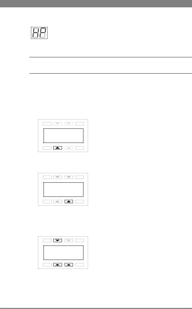
Locate the rotary/push button on the data board at the left. Rock the button to the left or right to select the required item. The segment display shows the code of the selected item.
Segment Rotary/push
display button
Note
When accessed from the base station, the user level is set to Install.
There are three items that can be selected:
Base station menu
When “NN” is displayed, push the rotary/push button twice to enter the base station menu. The rotary/push button can be used to navigate through the menu.
The menu appears on the Monitoring and CVBS + Text outputs of the base station.
Camera number
When “CA” is displayed, push the rotary/push button to enter the selection mode. Rock the button to the left or right to select an available camera number. Push the
rotary/push button again to confirm the new camera number. The base station automatically resets and the new camera number is shown in the display.
22 |
LDK 4410 + LDK 5420 3G Fiber Transmission System User’s Guide (v1.0) |
Chapter 2 - Base station
H-Phase adjustment
When “HP” is displayed, push the rotary/push button to enter the H-Phase adjustment mode. Rock the button to the left or right to shift the H-Phase. If you
continue to rock the button, the shift change occurs in bigger steps. Push the rotary/push button again to leave the H-Phase adjustment mode.
Note
This item is only available when a reference signal is present.
2.2.2Using the OCP
The OCP can be used access the base station menu instead of the rotary/push button.
1.Push the Setup button on the OCP to open the menu.
2.Push the selection button to choose the BS menu.
EXIT |
TOGGLE |
Diag |
OCP |
BS |
Cam |
PREV |
NEXT |
3.Push the selection button enter the Menu
EXIT |
TOGGLE |
|
Menu |
PREV |
NEXT |
4.The menu appears on the Monitoring and CVBS + Text outputs of the base station. Use the appropriate selection buttons to navigate the menu. You can also use the rotary contol on the OCP to move up or down through the menu.
EXIT |
TOGGLE |
|
UP |
|
DOWN SELECT |
PREV |
NEXT |
LDK 4410 + LDK 5420 3G Fiber Transmission System User’s Guide (v1.0) |
23 |
Chapter 2 - Base station
Note
When accessed from the OCP, the user level is set to Operator.
2.2.3Menu navigation
The base station menu is used for configuring the base station. As there are a large number of functions and set-up options available, it may require some time to become familiar with them all. The menu video signal is available on the Monitoring and CVBS+Text outputs.
Entering the menu
Use the rotary/push button at the front of the base station or the Operational Control Panel to access the base station menu. The functions of the base station are grouped into menus and sub-menus. When accessed, the main menu appears on the monitor.
MENU OFF
 Video
Video
Monitoring
Audio/Intercom 
SDTV
System
Root
Files
Diagnostics
The main menu screen shows five items and the name of the menu. One or more item can be hidden but become visible when you scroll down. A cursor shows your position in the menu. The navigation buttons (rotary/push button or OCP buttons) move the cursor up and down.
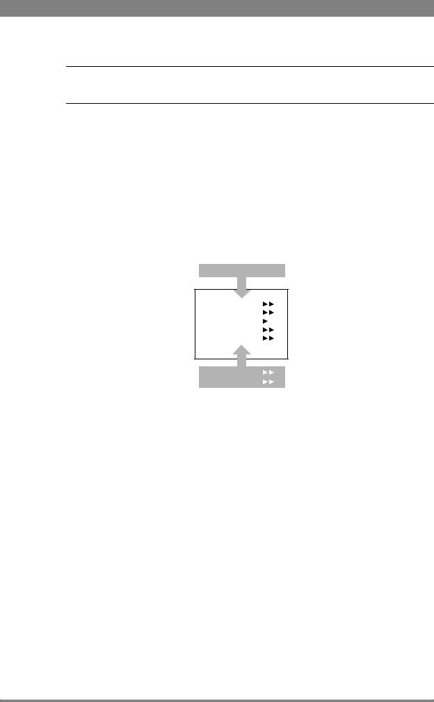
Finding your way
Use navigation buttons to move the cursor through the menu items. If a double arrow (>>) is visible, then pressing the rotary/push button or the SELECT button brings you one level lower in the menu system. Only five items are visible in each menu. Scroll up or down to see more items.
When you first enter a menu (other than the main menu) the cursor is positioned next to the first item. The TOP and PREVIOUS entries are not immediately visible but are located above the first item. Use the control to scroll up to them.
24 |
LDK 4410 + LDK 5420 3G Fiber Transmission System User’s Guide (v1.0) |

Chapter 2 - Base station
•Select TOP to bring you back to the MAIN menu.
•Select PREVIOUS to go back to the menu that you were in before the current one.
TOP
PREVIOUS
 Camera Number 1
Camera Power |
On |
MCP Available |
Yes |
Yellow On Air |
Std |
Timing |
|
System |
|
|
|
Clock |
|
Video Mode |
10i59 |
Teleprompter |
Off |
The SYSTEM menu above shows the items displayed when you first enter the menu and the other items that are available by scrolling up or down.
Leaving the menu
If you are deep within the menu structure, follow these steps to leave:
•If necessary move the cursor to the left most column.
•Scroll upwards until the cursor points to TOP (this is the main menu).
•Press the rotary/push button or the SELECT button on the OCP. The cursor now points to the Menu off item of the MAIN menu.
•Press the rotary/push button or the SELECT button on the OCP to leave the system menu.
This is the recommended way of leaving the system menu. The menu system disappears after a few seconds when you stop navigating. This delay can be set in the MONITORING > MENU
menu. However, when you enter the system menu again you enter at the last position of the cursor and not at the top of main menu. To prevent confusion the next time you enter the system menu, it is advisable to leave the system menu by returning to the main menu (TOP) and selecting MENU OFF.
Making changes
To find out where to change a function, consult “Base station menu” on page 47to find out under which menu group or subgroup the function is located. If the cursor points to an item (and there are no double arrows to indicate a sub-menu) then the item pointed to has a value. The value can be:
•a toggle value (only two values)
•a list value (more than two values)
•an analogue value (variable from 00 to 99)
•or unavailable (---).
If the value is unavailable it cannot be changed. This is indicated by three dashes (---). This can occur, for example, when a function is switched off. The analogue values associated with that function are then unavailable. If there are only two values associated with the function, then
LDK 4410 + LDK 5420 3G Fiber Transmission System User’s Guide (v1.0) |
25 |
Loading...