


 Loading...
ADX-1901
3G/HD/SD 8 Channel Analog Audio De-Embedder
Guide to Installation and Operation
M3005-9900-101
2015-04-29

GUIDE TO INSTALLATION AND OPERATION
Electromagnetic Compatibility
This equipment has been tested for verification of compliance with FCC Part 15, Subpart B requirements for Class A digital devices.
NOTE: This equipment has been tested and found to comply with the limits for a Class A digital device, pursuant to part 15 of the FCC Rules. These limits are designed to provide reasonable protection against harmful interference when the equipment is operated in a commercial environment. This equipment generates, uses, and can radiate radio frequency energy and, if not installed and used in accordance with the instruction manual, may cause harmful interference to radio communications. Operation of this equipment in a residential area is likely to cause harmful interference in which case the user will be required to correct the interference at his own expense.
This equipment has been tested and found to comply with the requirements of the EMC directive 2004/108/CE:
•EN 55022 Class A radiated and conducted emissions
•ENV 50204 Radiated EMF Immunity – RF 900 MHz Pulsed
•EN 61000-3-2 Harmonic current emission limits
•EN 61000-3-3 Voltage fluctuations and flicker limitations
•EN 61000-4-2 Electrostatic discharge immunity
•EN 61000-4-3 Radiated electromagnetic field immunity – radio frequencies
•EN 61000-4-4 Electrical fast transient immunity
•EN 61000-4-5 Surge transient immunity
•EN 61000-4-11 Voltage-dips, short-interruption and voltage variation immunity
ADX-1901
GUIDE TO INSTALLATION AND OPERATION
Table of Contents
1 ADX-1901 3G/HD/SD 8 Channel Analog Audio DeEmbedder |
..............................................1 |
|||
|
1.1 |
Introduction ......................................................................................................................................... |
1 |
|
|
1.2 |
Features .............................................................................................................................................. |
1 |
|
|
1.3 |
Functional Block Diagram ................................................................................................................... |
2 |
|
|
1.4 |
Front Card-edge Interface................................................................................................................... |
2 |
|
2 |
Installation |
................................................................................................................................ |
3 |
|
|
2.1 |
Installation ................................................................................................of Rear Connector Panels |
3 |
|
|
2.2 |
ADX-1901 ................................................................................................................Card Installation |
4 |
|
|
2.3 |
Installation ........................................................................................of the Optical Interface (option) |
4 |
|
|
2.4 |
Rear Panels ..............................................................................................................and Connectors |
5 |
|
|
|
2.4.1 ......................................................................................... |
Images of Rear Panel Connectors |
5 |
|
|
2.4.2 ...................................................................................... |
Summary of rear panel connections |
5 |
|
|
2.4.3 .......................................................................................... |
Details of rear panel connections |
6 |
3 |
User Interface........................................................................................................................... |
8 |
||
|
3.1 |
Control ....................................................................................................................................options |
8 |
|
|
3.2 |
Card-Edge .......................................................................................................................Status LED |
8 |
|
4 Local control ............................................................using the Densité frame control panel |
9 |
|||
|
4.1 |
Overview ............................................................................................................................................. |
9 |
|
|
4.2 |
Menu for ........................................................................................................................local control |
10 |
|
5 Remote control ..............................................................................................using iControl |
11 |
|||
|
5.1 |
The iControl ..............................................................................................graphic interface window |
11 |
|
|
5.2 |
Video Input/Output ..................................................................................................................panel |
13 |
|
|
|
5.2.1 ......................................................................... |
Video Input/Output panel (no fiber support) |
14 |
|
|
5.2.2 ......................................................................... |
Video Input/Output panel with fiber support |
14 |
|
5.3 |
Metadata .................................................................................................................................panel |
15 |
|
|
|
5.3.1 ........................................................................................................................... |
TC - GPI tab |
15 |
|
|
5.3.2 .............................................................................................................................. |
Audio tab |
16 |
|
5.4 |
Audio Inputs ............................................................................................................................panel |
17 |
|
|
|
5.4.1 .............................................................................................. |
CH 1 - 4, 5 - 8, 9 - 12, 13 - 16 tabs |
17 |
|
|
5.4.2 ..................................................................................................................... |
The Status tab: |
18 |
|
5.5 |
Audio Output ...........................................................................................................................panel |
18 |
|
|
|
5.5.1 .......................................................................................................... |
1 - 2, 3 - 4, 5 - 6, 7 - 8 tabs |
18 |
|
|
5.5.2 ............................................................................................................................. |
Config tab |
19 |
|
5.6 |
Audio Programs ......................................................................................................................panel |
20 |
|
|
5.7 |
Downmix ..................................................................................................................................panel |
21 |
|
|
5.8 |
Loudness ................................................................................................................................Panel |
22 |
|
|
|
5.8.1 ...................................................................................................... |
Loudness | Config panel |
22 |
|
|
5.8.2 ........................................................................................................ |
Loudness | PGM panel |
23 |
|
5.9 |
Alarms .....................................................................................................................................panel |
24 |
|
|
|
5.9.1 ........................................................................................................... |
Alarms – Video panel |
24 |
|
|
5.9.2 ..................................................................................................... |
Alarms – Metadata panel |
25 |
|
|
5.9.3 ........................................................................................................... |
Alarms – Audio panel |
26 |
|
5.10 |
Monitoring ................................................................................................................................panel |
29 |
|
|
|
5.10.1 ........................................................................................................ |
RALM Connections tab |
29 |
ADX-1901
GUIDE TO INSTALLATION AND OPERATION |
|
||
|
5.10.2 Meter Ballistics Config tab.................................................................................................... |
29 |
|
5.11 |
Test panel.......................................................................................................................................... |
30 |
|
5.12 |
Factory/Presets panel........................................................................................................................ |
31 |
|
5.13 |
Alarm Config panel ............................................................................................................................ |
33 |
|
5.14 |
Info panel........................................................................................................................................... |
36 |
|
6 Specifications ........................................................................................................................ |
38 |
||
7 Grass Valley Technical Support ........................................................................................... |
40 |
||
ANNEX 1 |
– ADX-1901 Local User Interface................................................................................ |
41 |
|
ANNEX 2 |
– Installing the Optical Interface ................................................................................ |
42 |
|
ANNEX 3 |
- Loudness Logging and the Miranda Audio Loudness Analyzer............................ |
44 |
|
ADX-1901
GUIDE TO INSTALLATION AND OPERATION
1 ADX-1901 3G/HD/SD 8 Channel Analog Audio DeEmbedder
1.1Introduction
The ADX-1901 is an advanced, high quality 24-bit 48 KHz analog audio de-embedder designed to extract eight analog audio signals from a 3G/HD/SD video signal. The ADX-1901 can process the 8 audio de-embedded channels with functions including level, channel shuffling and mixing.
The loudness measurement features allows the measurement and logging of up to 8 audio programs with iControl Loudness Monitoring software to analyze and report compliance with respect to various loudness legislation around the world. Furthermore, a delay of up to 2.7 seconds can be programmed independently per de-embedded audio channel to provide lip sync correction.
The ADX-1901 can de-embed Ancillary Time Code (ATC) in 3Gbps/HD, or DVITC in SD, to generate Linear Time Code (LTC). Up to two GPIO can be generated by extracting GPI events from the Time Code user bits in transport applications. Audio Metadata extraction from the VANC can be streamed to an external RS-422 output.
The ADX-1901 is designed for the Densité 2 frame, but will be compatible with the Densité 3 frame with the metal extender. Multiple rear connector panels are available according to your application needs and the chassis type used.
A fiber input/output cartridge is offered as an option on some rear modules. Once the cartridge is installed, the input or outputs are selectable through the control interface.
1.2Features
Audio
•8 analog audio outputs
•Audio silence output on loss of video input.
•Full audio shuffling and mixing on a channel output basis
•Individually adjustable audio output levels
•Audio 5.1 surround downmix to Lo/Ro
•Audio delay adjustments of up to 2.7 seconds to compensate for lip sync issues
•Built in test generator (audio).
•Monitoring and reporting of audio output Max/Min Level, Silence and Phase.
•Loudness measurement of up to 8 audio programs and logging with iControl Loudness Monitoring software
•Loudness compliant to EBU R128, ATSC A/85:2013 and ARIB TR-B32 (ITU-R BS.1770-3))
Video
•3Gbps/HD/SD input with automatic equalization
•Supports 3Gbps level A (mapping 1) and level B
•Automatic detection of video input format
•Optional optical fiber SFP cartridge
•Black Detection monitoring
Metadata
•Linear Time Code (LTC) output translated from DVITC (SD) or ATC (3Gbps/HD)
•2 GPI data output signals reconstructed from ANC TC user bits.
•RS-422 serial data output to carry Audio Metadata (SMPTE 2020-A) from the VANC.
ADX-1901 | 1

GUIDE TO INSTALLATION AND OPERATION
1.3Functional Block Diagram
Figure 1.1 ADX-1901 Functional Block Diagram
1.4Front Card-edge Interface
The front card-edge of the ADX-1901 incorporates two elements:
•Status LED (see section 3.2)
•Select Button (see section 4)
|
Status |
Select |
ADX-1901 |
|
|
|
|
Select Button |
|
|
Status LED |
Figure 1.2 |
Front card-edge layout |
|
2 | ADX-1901
GUIDE TO INSTALLATION AND OPERATION
2 Installation
2.1Installation of Rear Connector Panels
Grass Valley Densité-series cards are each associated with a rear connector panel, which must be installed in the Densité frame before the card can be inserted.
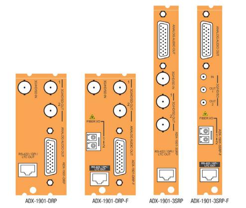
The ADX-1901 card is designed to fit into Grass Valley’s Densité-2 frame. Two different rear connector panels are available for this configuration. Due to connector space requirements, a double-slot-width rear panel is necessary:
• |
ADX-1901-DRP |
Double-slot-width panel for Densité-2 |
• |
ADX-1901-DRP-F |
Double-slot-width panel for Densité-2 with fiber I/O |
With a factory-installed adapter mounted on the ADX-1901 card, it can be installed in a Densité-3 frame. In this case, only a single-slot-width panel is required. Two rear panels are available:
• |
ADX-1901-3SRP |
Single-slot-width panel for Densité-3 |
• |
ADX-1901-3SRP-F |
Single-slot-width panel for Densité-3 with fiber I/O |
See section 2.4 for details of the signal connections available on each of these panel types.
All cards and rear panels can be installed with the frame power on. The card has connectors which plug into a midframe mother board for distribution of power and for connection to the controller card, and a second connector which plugs directly into the rear connector panel for input and output.
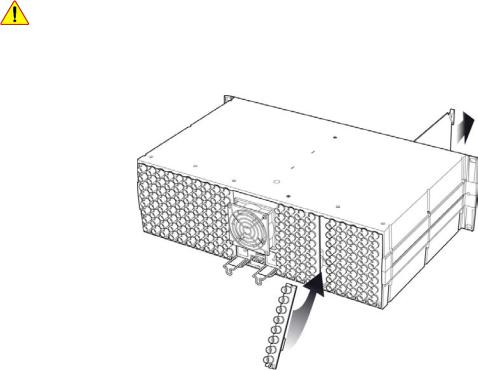
The rear connector panel must be installed with the card out of the frame.
•To remove an existing card from the slot, tilt up the swivel handle on the front of the card to lever the connectors apart, then use the handle to pull the card straight out of the slot.
Figure 2.1 Densité-3 frame – rear panel installation
ADX-1901 | 3
GUIDE TO INSTALLATION AND OPERATION
To install the connector panel:
Note – the procedure is the same for both Densité-2 and Densité-3 frames.
1.If a card is installed in the slot whose rear panel is being changed, remove it as described above.
2.Remove the existing panel (either blank or belonging to an existing card that is being changed) by releasing the captive screw(s) at the bottom.
3.Position the new panel and secure it in place with the captive screw(s) at the bottom.
2.2ADX-1901 Card Installation
Note – The card itself (ADX-1901) is designed to fit the Densité-2 frame. If it was ordered for the Densité-3 frame (ADX-1901-3RU), it will be delivered with an installed adapter that allows it to fit into the taller frame. The adapter can be ordered separately and user-installed if required.
Once a matching rear connector panel is in place, install the ADX-1901 card as follows:
1.Open the front panel of the frame.
2.Slide the ADX-1901 card into the slot and push gently on the handle to seat the connectors.
When using the double-slot-width rear panel in a Densité-2 frame, the card should be inserted into the rightmost of the two slots. Inserting the card into the wrong slot will not damage the card, and will be flagged by the on-card status LED flashing red to indicate that there is no connection to the rear panel.
3.Close the front panel of the frame.
2.3Installation of the Optical Interface (option)
Refer to ANNEX 2.
4 | ADX-1901
GUIDE TO INSTALLATION AND OPERATION
2.4Rear Panels and Connectors
2.4.1Images of Rear Panel Connectors
The four available rear panels are shown in the figure.
Details of the inputs and outputs are described below.
2.4.2 Summary of rear panel connections
ADX-1901-3SRP |
|
|
|
|
ADX-1901-3SRP-F |
|
|
|
|
|
|
|
|
|
ADX-1901-DRP |
|
|
|
|
ADX-1901-DRP-F |
|
|
|
|
|
|
|
|
|
|
|
|
|
|
Single-slot-width panel |
|
|
♦ |
♦ |
Double-slot-width panel |
♦ |
♦ |
|
|
CONNECTORS |
|
|
|
|
3G/HD/SD IN |
1 |
1 |
1* |
1 |
3G/HD/SD OUT |
2 |
2 |
2* |
2 |
Analog Audio OUT on D-SUB |
8 |
8 |
8 |
8 |
2 GPI OUT, LTC OUT & RS-422 OUT on RJ45 |
yes |
yes |
yes |
yes |
Fiber I/O module |
yes |
|
yes |
|
|
|
|
|
|
* DIN1.0/2.3 connectors on ADX-1901-3SRP-F panel; BNC connectors on all other panels.
ADX-1901 | 5
GUIDE TO INSTALLATION AND OPERATION
2.4.3Details of rear panel connections
3G/HD/SD IN – Serial digital 3G/HD/SD input
Connect a serial digital video signal, conforming to the SMPTE 425M standard for 3G input signals, SMPTE 292M standard for HD input signals or SMPTE 259M standard for SD input signals, to the connector labeled 3G/HD/SD IN. The ADX-1901 will automatically switch to the detected line/frame rate format.
3G/HD/SD OUT – Serial digital video outputs
The ADX-1901 provides two 3G/HD/SD SDI video outputs on the connectors labeled 3G/HD/SD OUT 1 and 2. The SDI video signal conforms to the input standard. The same signal is carried on both outputs.
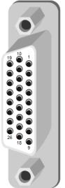
ANALOG AUDIO OUT – Analog audio outputs (8)
The eight analog audio outputs are balanced outputs, via a 26-pin D-SUB female connector. Pinout for the connector is shown in the table.
Signal |
Pin # |
|
AUDIO OUT 1 (Hi) |
1 |
|
|
|
|
AUDIO OUT 1 (Lo) |
10 |
|
|
|
|
AUDIO OUT 2 (Hi) |
2 |
|
|
|
|
AUDIO OUT 2 (Lo) |
11 |
|
|
|
|
AUDIO OUT 3 (Hi) |
3 |
|
|
|
|
AUDIO OUT 3 (Lo) |
12 |
|
|
|
|
AUDIO OUT 4 (Hi) |
4 |
|
|
|
|
AUDIO OUT 4 (Lo) |
13 |
|
|
|
|
AUDIO OUT 5 (Hi) |
5 |
|
|
|
|
AUDIO OUT 5 (Lo) |
14 |
|
|
|
|
AUDIO OUT 6 (Hi) |
6 |
|
|
|
|
AUDIO OUT 6 (Lo) |
15 |
|
|
|
|
AUDIO OUT 7 (Hi) |
7 |
|
|
|
|
AUDIO OUT 7 (Lo) |
16 |
|
|
|
|
AUDIO OUT 8 (Hi) |
8 |
|
|
|
|
AUDIO OUT 8 (Lo) |
17 |
|
|
|
|
GND |
9, 18 to 26 |
|
|
|
Fiber I/O – Fiber-optic inputs and outputs
Rear panels whose part number ends in –F incorporate a fiber optic interface. The interface consists of two parts:
•A socket on the rear panel into which an SFP interface module is plugged
•An SFP (Small Form-factor Pluggable) module into which the optical fibers are plugged, and which incorporates the optical/electrical interface
The optical fibers must be terminated in an LC/PC connector.
6 | ADX-1901
GUIDE TO INSTALLATION AND OPERATION
See ANNEX 2 for instructions on installing and removing the SFP interface module, and for plugging and unplugging the LC-terminated fibers.
The SFP modules supported by the ADX-1901 are:
SFP Modules |
Description |
SFP-T-S13-LC |
Single fiber Tx (output) module at 1310 nm with LC/PC connector |
|
|
SFP-TT-S13S13-LC |
Dual fiber Tx (output) module at 1310 nm with LC/PC connector |
SFP-RT-S13-LC |
Dual fiber Rx (input) and Tx (output) module at 1310 nm with LC/PC connectors |
|
|
SFP-R-LC |
Single fiber Rx (input) module with LC/PC connector |
SFP-RT-W13-LC |
Single fiber Rx/Tx module at 1310 nm with WDM, LC/PC connector |
SFP-RT-W15-LC |
Single fiber Rx/Tx module at 1550 nm with WDM, LC/PC connector |
|
|
RS-422 / GPI / LTC – Metadata Output, GPI Outputs and Timecode Output
RS-422, GPI and LTC signals are carried on an RJ-45 connector, with the pinout as shown in the table:
|
Function |
Pin # |
|
NC |
1 |
|
|
|
|
NC |
2 |
|
RS422-TX-1 |
3 |
|
LTC OUTPUT |
4 |
Note: A GPI output is open when inactive and connected to ground when active. |
|
|
GPIO USER2 OUTPUT |
5 |
|
|
RS422-TX-0 |
6 |
|
GPIO USER1 OUTPUT |
7 |
|
|
|
|
GND |
8 |
ADX-1901 | 7

GUIDE TO INSTALLATION AND OPERATION
3 User Interface
3.1Control options
The ADX-1901 can be controlled in three different ways:
•The local control panel and its push-buttons can be used to move through a menu of parameters and to adjust parameter values (see section 4).
•Grass Valley’s iControl system can be used to access the card’s operating parameters from a remote computer, using a convenient graphical user interface (GUI) (see section 5).
•Grass Valley’s RCP-200 panel (check for availability).
3.2Card-Edge Status LED
The status monitor LED is located on the front card-edge of the ADX-1901, and is visible through the front access door of the DENSITÉ frame. This multi-color LED indicates the status of the ADX-1901 by color, and by flashing/steady illumination.
The chart shows how the various error conditions that can be flagged on the ADX-1901 affect the LED status.
•If a cell is gray, the error condition cannot cause the LED to assume that status
•If more than one LED status is possible for a particular error condition, the status is configurable. See section 5.16 for details.
•The factory default status is shown by a
The LED will always show the most severe detected error status that it is configured to display, and in the chart error severity increases from left to right, with green representing no error/disabled, and flashing red the most severe error.
If the LED is Flashing Yellow, it means that the card is selected for local control using the Densité frame’s control panel. See section 4.1 for details.
|
|
|
|
LED Status |
|
|
||
Error Condition |
|
Green |
|
Yellow |
|
Red |
Flashing |
|
|
|
|
Red |
|
||||
|
|
|
|
|
|
|
||
Hardware failure |
|
|
|
|
|
|
|
|
No Rear |
|
|
|
|
|
|
|
|
SFP – Absence |
|
|
|
|
|
|
|
|
|
|
|
|
|
|
|
|
|
SFP – Type mismatch |
|
|
|
|
|
|
|
|
|
|
|
|
|
|
|
|
|
SFP – Temperature 1 |
|
|
|
|
|
|
|
|
|
|
|
|
|
|
|
|
|
SFP – Optical Power 1 |
|
|
|
|
|
|
|
|
|
|
|
|
|
|
|
|
|
SFP – Voltage 1 |
|
|
|
|
|
|
|
|
|
|
|
|
|
|
|
|
|
SFP – Temperature 2 |
|
|
|
|
|
|
|
|
SFP – Optical Power 2 |
|
|
|
|
|
|
|
|
SFP – Voltage 2 |
|
|
|
|
|
|
|
|
Video – Input video error |
|
|
|
|
|
|
|
|
|
|
|
|
|
|
|
|
|
Video – input Black Detect |
|
|
|
|
|
|
|
|
|
|
|
|
|
|
|
|
|
Video – Audio MTDT absent |
|
|
|
|
|
|
|
|
|
|
|
|
|
|
|
|
|
Metadata – SMPTE 2020 |
|
|
|
|
|
|
|
|
|
|
|
|
|
|
|
|
|
Metadata – DVITC.ATC |
|
|
|
|
|
|
|
|
|
|
|
|
|
|
|
|
|
Audio – TP Overload CH1 |
|
|
|
|
|
|
|
|
Audio – TP Overload CH8 |
|
|
|
|
|
|
|
|
|
|
|
|
|
|
|
|
|
8 | ADX-1901

|
GUIDE TO INSTALLATION AND OPERATION |
|||||
|
|
|
|
|
|
|
Audio – Silence Detection CH1 |
|
|
|
|
|
|
Audio – Silence Detection CH8 |
|
|
|
|
|
|
|
|
|
|
|
|
|
Audio – min loudness PGM1 |
|
|
|
|
|
|
Audio – min loudness PGM8 |
|
|
|
|
|
|
|
|
|
|
|
|
|
Audio – max loudness PGM1 |
|
|
|
|
|
|
Audio – max loudness PGM8 |
|
|
|
|
|
|
|
|
|
|
|
|
|
Audio – phase error CH1-2 |
|
|
|
|
|
|
Audio – phase error CH7-8 |
|
|
|
|
|
|
|
|
|
|
|
|
|
Audio – mute CH1 |
|
|
|
|
|
|
Audio – mute CH8 |
|
|
|
|
|
|
|
|
|
|
|
|
|
Audio - Test Tone |
|
|
|
|
|
|
|
|
|
|
|
|
|
4 Local control using the Densité frame control panel
4.1Overview
Push the SELECT button on the ADX-1901 card edge (see section 1.4) to assign the local control panel to operate the ADX-1901. Use the control panel buttons to navigate through the menu, as described below.
All of the cards installed in a Densité frame are connected to the frame’s controller card, which handles all interaction between the cards and the outside world. There are no operating controls located on the cards themselves. The controller supports remote operation via its Ethernet ports, and local operation using its integrated control panel.
The local control panel is fastened to the front of the |
Figure 4.1 Densité Frame local control panel |
|
CPU-ETH2 controller card, and when installed is located in the front center of the frame, positioned in front of the power supplies. The panel consists of a display unit capable of displaying two lines of text, each 16 characters in length, and five pushbuttons.
The panel is assigned to operate any card in the frame by pushing the SELECT button on the front edge of that card.
•Pushing the CONTROLLER button on the control panel selects the Controller card itself.
•The STATUS LED on the selected card flashes yellow.
The local control panel displays a menu that can be navigated using the four pushbuttons located beside the display. The functionality of the pushbuttons is as follows:
ADX-1901 | 9
GUIDE TO INSTALLATION AND OPERATION
[+] [–] |
Used for menu navigation and value modification |
[SELECT] |
Gives access to the next menu level. When a parameter value is shown, pushing this button once |
|
enables modification of the value using the [+] and [–] buttons; a second push confirms the new value. |
[ESC] |
Cancels the effect of parameter value changes that have not been confirmed; pushing [ESC] causes the |
|
parameter to revert to its former value. |
|
Pushing [ESC] moves the user back up to the previous menu level. At the main menu, [ESC] does not |
|
exit the menu system. To exit, re-push the [SELECT] button for the card being controlled. |
If no controls are operated for 30 seconds, the controller reverts to its normal standby status, and the selected card’s STATUS LED reverts to its normal operating mode.
4.2Menu for local control
The ADX-1901 has operating parameters which may be adjusted locally at the controller card interface.
•Press the SELECT button on the ADX-1901 front card edge to assign the Densité frame’s local control panel to the ADX-1901
•Use the keys on the local control panel to step through the displayed menu to configure and adjust the ADX1901.
The complete menu structure is shown in ANNEX 1 to this document, beginning on page 41.
10 | ADX-1901
GUIDE TO INSTALLATION AND OPERATION
5 Remote control using iControl
The operation of the ADX-1901 may be controlled using Grass Valley’s iControl system.
•This manual describes the control panels associated with the ADX-1901 and their use.
•Please consult the iControl User’s Guide for information about setting up and operating iControl.
In iControl Navigator or iControl Websites, double-click on the ADX-1901 icon to open the control panel.
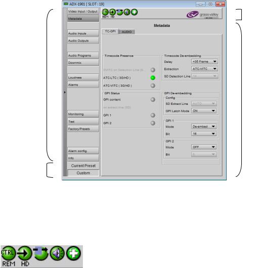
5.1The iControl graphic interface window
The basic window structure for the ADX-1901 is shown in figure 5.1. The window identification line gives the card type (ADX-1901) and the slot number where the card is installed in its Densité frame.
There are four main sections in the window itself, as identified in the figure:
1
2
4
3
Figure 5-1 ADX-1901 iControl graphic interface window
Section 1. The top section displays five icons on the left. These icons report different statuses such as card communication status, input signal and reference signal format and statuses. In some instances, they relate to conditions defined through parameters settings.
Icon # 1 |
2 |
3 |
4 |
5 |
Move the mouse over an icon and a status message appears below the icon providing additional information.
ADX-1901 | 11
Loading...