


Kaleido-Modular-X
Table of contents
 Loading...
Quick Start Guide
M933-9805-108
2015-04-02
KALEIDO-MODULAR-X
HIGH PICTURE COUNT, ULTRA-FLEXIBLE AND SCALABLE
MULTIVIEWER

ii
Notices
Copyright & Trademark Notice
Copyright © 2013–2015, Grass Valley USA, LLC. All rights reserved.
Belden, Belden Sending All The Right Signals, and the Belden logo are trademarks or
registered trademarks of Belden Inc. or its affiliated companies in the United States and
other jurisdictions. Grass Valley, Kaleido-Modular-X, iControl, NVISION, and Densité are
trademarks or registered trademarks of Grass Valley USA, LLC. Belden Inc., Grass Valley USA,
LLC, and other parties may also have trademark rights in other terms used herein.
Terms and Conditions
Please read the following terms and conditions carefully. By using Kaleido multiviewer
documentation, you agree to the following terms and conditions.
Grass Valley hereby grants permission and license to owners of Kaleido multiviewers to use
their product manuals for their own internal business use. Manuals for Grass Valley
products may not be reproduced or transmitted in any form or by any means, electronic or
mechanical, including photocopying and recording, for any purpose unless specifically
authorized in writing by Grass Valley.
A Grass Valley manual may have been revised to reflect changes made to the product
during its manufacturing life. Thus, different versions of a manual may exist for any given
product. Care should be taken to ensure that one obtains the proper manual version for a
specific product serial number.
Information in this document is subject to change without notice and does not represent a
commitment on the part of Grass Valley.
Warranty information is available in the Support section of the Grass Valley Web site
(www.grassvalley.com).
The SDHC Logo is a trademark of SD-3C, LLC.
Title Kaleido-Modular-X Quick Start Guide
Part Number M933-9805-108
Revision 2015-04-02, 19:14
iii
Kaleido-Modular-X
Quick Start Guide
Electrostatic Discharge (ESD) Protection
Electrostatic discharge occurs when electronic components are improperly
handled and can result in intermittent failure or complete damage adversely
affecting an electrical circuit. When you remove and replace any card from a frame
always follow ESD-prevention procedures:
• Ensure that the frame is electrically connected to earth ground through the power cord
or any other means if available.
• Wear an ESD wrist strap ensuring that it makes good skin contact. Connect the
grounding clip to an unpainted surface of the chassis frame to safely ground unwanted
ESD voltages. If no wrist strap is available, ground yourself by touching the unpainted
metal part of the chassis.
• For safety, periodically check the resistance value of the antistatic strap, which should
be between
1 and 10 megohms.
• When temporarily storing a card make sure it is placed in an ESD bag.
• Cards in an earth grounded metal frame or casing do not require any special ESD
protection.
Protection contre les décharges électrostatiques (DES)
Une décharge électrostatique peut se produire lorsque des composants
électroniques ne sont pas manipulés de manière adéquate, ce qui peut entraîner
des défaillances intermittentes ou endommager irrémédiablement un circuit
électrique. Au moment de remplacer une carte dans un châssis, prenez toujours les
mesures de protection antistatique appropriées
:
• Assurez-vous que le châssis est relié électriquement à la terre par le cordon
d'alimentation ou tout autre moyen disponible.
• Portez un bracelet antistatique et assurez-vous qu'il est bien en contact avec la peau.
Connectez la pince de masse à une surface non peinte du châssis pour détourner à la
terre toute tension électrostatique indésirable. En l’absence de bracelet antistatique,
déchargez l’électricité statique de votre corps en touchant une surface métallique non
peinte du châssis.
• Pour plus de sécurité, vérifiez périodiquement la valeur de résistance du bracelet
antistatique. Elle doit se situer entre 1 et 10
mégohms.
• Si vous devez mettre une carte de côté, assurez-vous de la ranger dans un sac
protecteur antistatique.
• Les cartes qui sont reliées à un châssis ou boîtier métallique mis à la terre ne
nécessitent pas de protection antistatique spéciale.
Recycling
Visit www.grassvalley.com for recycling information.
iv
Notices
Electromagnetic Compatibility
This equipment has been tested for verification of compliance with FCC Part 15,
Subpart B requirements for class A digital devices.
This equipment has been tested and found to comply with the requirements of the
Electromagnetic Compatibility directive 2004/108/EC:
• EN 55022 Class A Radiated and conducted emissions
• EN 61000-3-2 Limits for harmonic current emissions
• EN 61000-3-3 Limitation of voltage fluctuations and flicker
• EN 61000-4-2 Electrostatic discharge immunity
• EN 61000-4-3 Radiated, radio-frequency, electromagnetic field immunity
• EN 61000-4-4 Electrical fast transient immunity
• EN 61000-4-5 Surge transient immunity
• EN 61000-4-6 Conducted disturbances immunity
• EN 61000-4-11 Voltage dips, short interruptions and voltage variations
immunity
Note: This equipment has been tested and found to comply with the limits
for a Class A digital device, pursuant to Part 15 of the FCC rules. These limits
are designed to provide reasonable protection against harmful interference
when the equipment is operated in a commercial environment. This
equipment generates, uses, and can radiate radio frequency energy, and, if
not installed and used in accordance with the instruction manual, may cause
harmful interference to radio communications. Operation of this equipment
in a residential area is likely to cause harmful interference in which case the
user will be required to correct the interference at his own expense.
1
Setting Up Your Kaleido-Modular-X System
Welcome to the Kaleido family of multiviewers! This Quick Start Guide is designed to help
you get your Kaleido-Modular-X multiviewer up and running for the first time. The
following sections will guide you through the installation of a Kaleido-Modular-X system in
its default configuration. For more information about the Kaleido-Modular-X hardware,
refer to the Kaleido-Modular-X Hardware Description & Installation Manual (on the DVD that
shipped with your system).
Summary
Introduction . . . . . . . . . . . . . . . . . . . . . . . . . . . . . . . . . . . . . . . . . . . . . . . . . . . . . . . . . . . . . . . . . . . . . . . . . . 1
Getting Organized . . . . . . . . . . . . . . . . . . . . . . . . . . . . . . . . . . . . . . . . . . . . . . . . . . . . . . . . . . . . . . . . . . . . 3
Step 1: Physical Setup . . . . . . . . . . . . . . . . . . . . . . . . . . . . . . . . . . . . . . . . . . . . . . . . . . . . . . . . . . . . . . . . . 5
Step 2: Networking Setup . . . . . . . . . . . . . . . . . . . . . . . . . . . . . . . . . . . . . . . . . . . . . . . . . . . . . . . . . . . . . 21
Step 3: XEdit Installation . . . . . . . . . . . . . . . . . . . . . . . . . . . . . . . . . . . . . . . . . . . . . . . . . . . . . . . . . . . . . . 38
Step 4: System Verification . . . . . . . . . . . . . . . . . . . . . . . . . . . . . . . . . . . . . . . . . . . . . . . . . . . . . . . . . . . . 41
RS-422 Connection Diagram . . . . . . . . . . . . . . . . . . . . . . . . . . . . . . . . . . . . . . . . . . . . . . . . . . . . . . . . . 47
Introduction
Grass Valley's Kaleido family of multiviewers ranges from quad-splits to large-scale, multi-
room monitoring systems, with outstanding image quality and signal flexibility. The
Kaleido multiviewers are available in different models: the Kaleido-MX, the Kaleido-IP, the
Kaleido-X (7RU), the Kaleido-X (4RU), the Kaleido-X16, and the Kaleido-XQUAD frames, as
well as the Kaleido-Modular-X cards, and the Kaleido-Modular KMV-3901/3911 cards.
The Kaleido-Modular-X offers a flexible and scalable multiviewer solution for TV
production optimized for the space, power and weight considerations found in studios and
outside broadcast trucks. FlexBridge coax cable bridging between the input and output
modules allows for the installation of the input stage next to the router or sources, and the
output stage next to displays, for simpler, cost-effective cabling with none of the risk
associated with HDMI extenders. The Kaleido-Modular-X supports up to 64
video inputs,
and up to four multiviewer outputs.
At the heart of every multiviewer system is the Kaleido-X software, which includes the
following client applications:
• XAdmin is a Web client that your system administrator will use to manage the
multiviewer system.
• XEdit is a client application used to create layouts for the monitor wall, and to configure
the multiviewer, from your PC or laptop.
•The Router Control Software Single Bus and Matrix View applications (also part of the
iRouter Router Control Software packaged with iControl Application Servers) can be
used to control your multiviewer’s logical sources and monitor wall destinations, via
2
Setting Up Your Kaleido-Modular-X System
Introduction
the KX Router logical router, or to control other logical routers configured within your
multiviewer system.
• Signal Path Viewer opens as a standalone panel, updated in real time, showing
assignment information between router sources and multiviewer inputs. Signal Path
Viewer is available for all multiviewer models, except Kaleido-IP (for which it is not
relevant).
A Kaleido-Modular-X multiviewer system in its default configuration includes a number of
layout presets. Each preset shows the video signals from a specific input module (card).
Refer to the Kaleido-X User’s Manual (on the DVD that shipped with your multiviewer) for
instructions on how to create rooms and layouts according to your specific requirements.
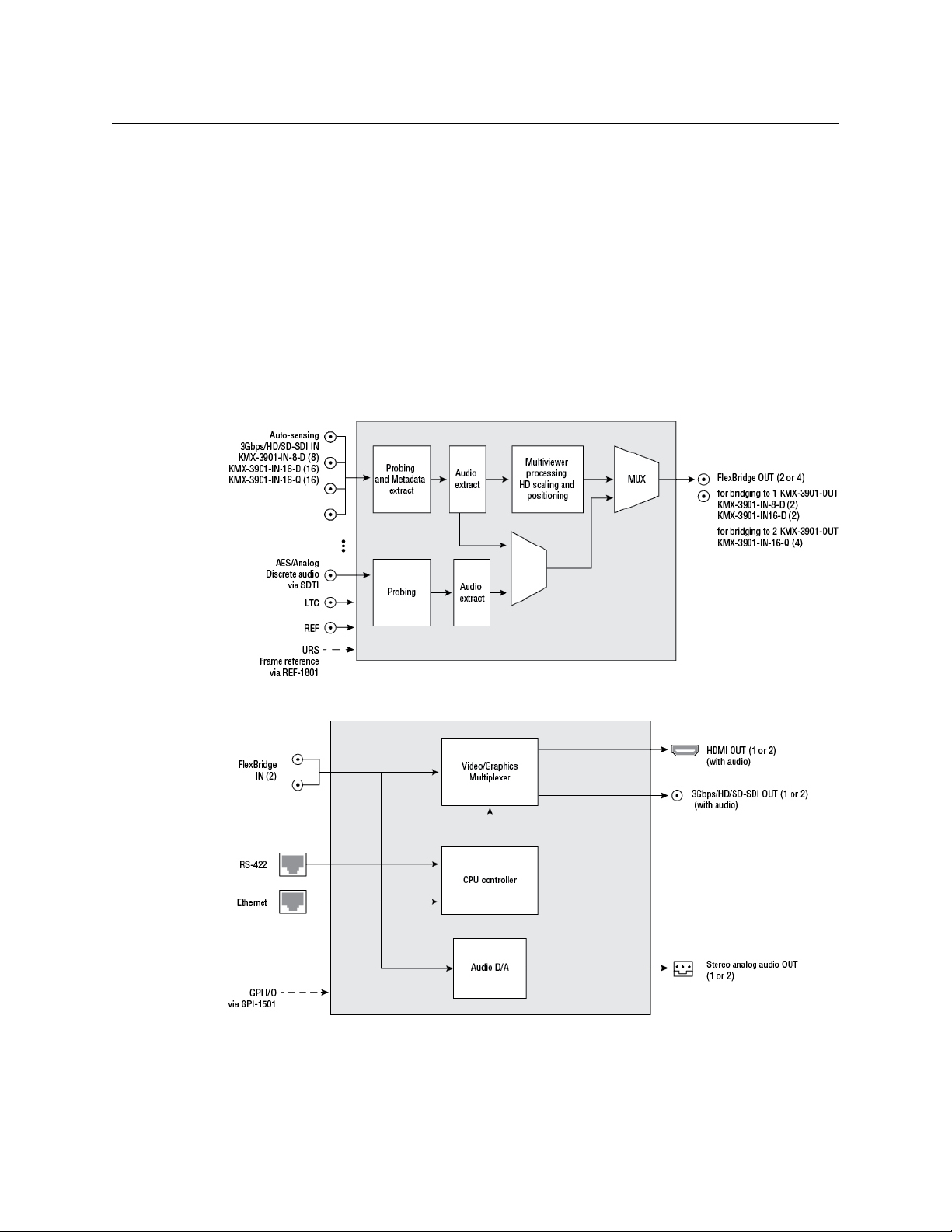
Functional block diagrams
Kaleido-Modular-X functional block diagram: KMX-3901-IN input module
Kaleido-Modular-X functional block diagram: KMX-3901-OUT output module

3
Kaleido-Modular-X
Quick Start Guide
Getting Organized
This section provides information about system requirements, and items shipped with your
Kaleido-Modular-X.
Required Materials
Your Kaleido-Modular-X system package includes the following:
• 1–4 KMX-3901-IN input cards with matching rear modules, as per order
• 1–4 KMX-3901-IN-M3 rear modules, M3 cables, and NVISION router-side rears, as per
order
• 1 or 2 KMX-3901-OUT output cards, with rear modules, as per order
• 1–16 12-inch FlexBridge cables (DIN-DIN coax cables), as per order
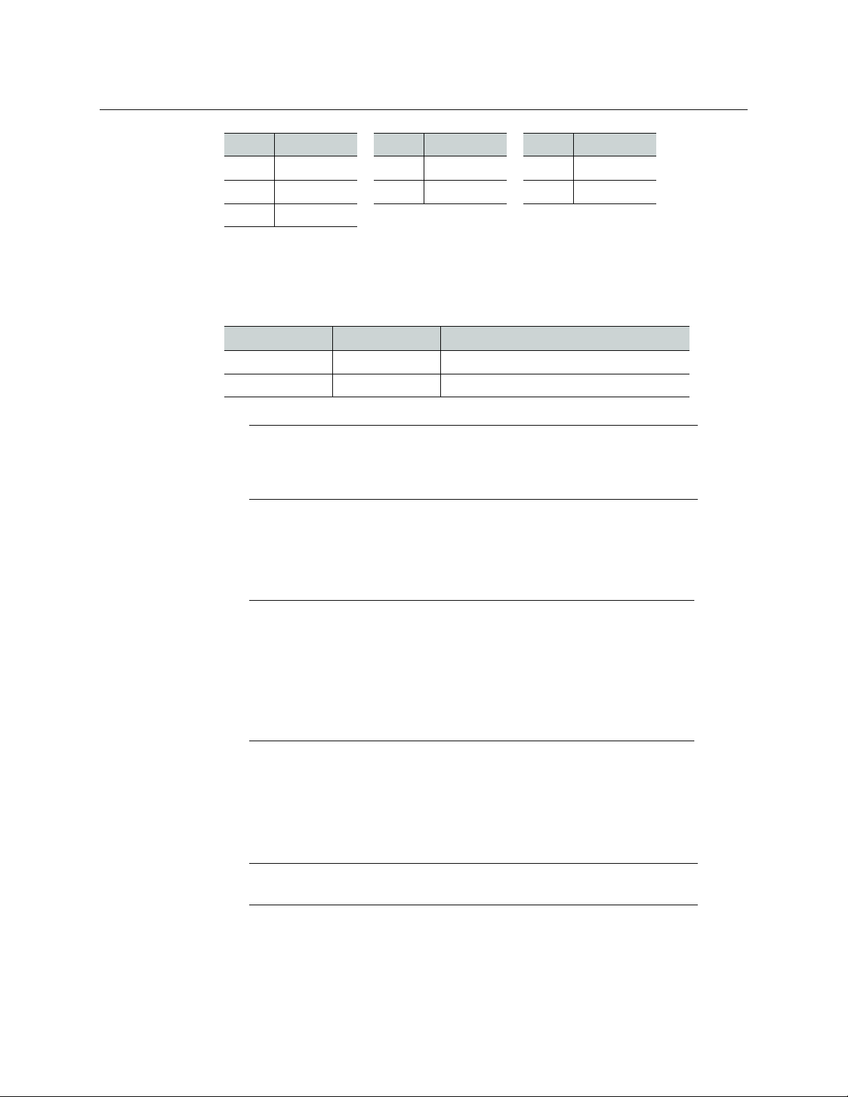
Input module parts Description
KMX-3901-IN-8-D 8 input HD/SD-SDI and 3 Gbps input module with dual
FlexBridge outputs.
KMX-3901-IN-8-D-3TRP Triple rear connector panel with bypass relay.
KMX-3901-IN-16-D 16 input HD/SD-SDI and 3 Gbps input module with dual
FlexBridge outputs.
KMX-3901-IN-16-D-3QRP Quadruple rear connector panel with bypass relay.
KMX-3901-IN-16-Q 16 input HD/SD-SDI and 3 Gbps input module with quad
FlexBridge outputs. convertible to a 4K UHD prescaler.
KMX-3901-IN-16-Q-3PRP Quintuple rear connector panel with bypass relay.
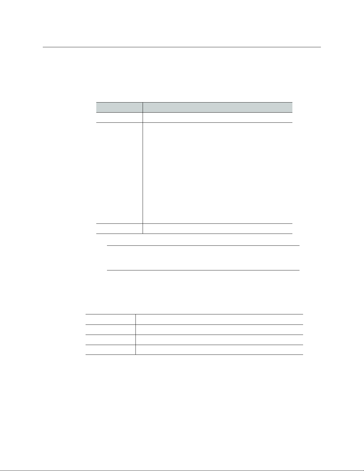
M3 module parts Description
KMX-3901-IN-M3-D-3PRP Quadruple rear connector panel with bypass relay for the M3
cable. Use with KMX-3901-IN-16-D.
KMX-3901-IN-M3-Q-3PRP Quintuple rear connector panel with bypass relay for the M3
cable. Use with KMX-3901-IN-16-Q.
Output module parts Description
KMX-3901-OUT-S Single head output module, upgradable to dual head outputs.
KMX-3901-OUT-D Dual head output module.
KMX-3901-OUT-D-3DRP Double rear connector panel.
KMX-3901-OUT-D-3+SRP Single rear connector panel. Compatible with Densité 3+ FR1
only.
Model FlexBridge Model FlexBridge Model FlexBridge
8 × 1 1 24 × 1 2 48 × 2 6
8 × 2 2 24 × 2 4 48 × 4 12
4
Setting Up Your Kaleido-Modular-X System
Getting Organized
• 2 WECO analog audio mating connectors for each output card
• 2 serial port adapters (1 with straight cabling and 1 with crossover cabling — see RS-
422 Connection Diagram, on page 47) for every output card ordered with a double rear
connector panel
• The Kaleido-Modular-X Quick Start Guide (this document)
• DVD including the Release Notes for the current version of the Kaleido-X software, the
Kaleido-X User’s Manual, database samples, Quick Start guides and hardware reference
manuals for all multiviewer models
In addition to the above, you might need the following (not supplied):
• At least one Densité 3 housing frame
• For a quad-head system with 64 inputs, or if you wish to have separate input and
output stages, then you will also need a separate Densité 3 or Densité
3+ FR1 frame to
house your output cards
• A Densité CPU-ETH2 controller card for each housing frame
(Optionally: a GPI-1501 GPI I/O module, a REF-1801 HD/SD frame reference module)
•Up to 4 displays
16 × 1 1 32 × 2 4 64 × 2 8
16 × 2 2 32 × 4 8 64 × 4 16
16 × 4 4
Part number Adapter cabling RS-422 pinout at the DE-9P connector
1737-3000-102 Straight Controller (SMPTE master) mode
1792-3700-100 Crossover Tributary (SMPTE slave) mode
Note: The single rear connector panel KMX-3901-OUT-D-3+SRP does not
have a serial port. To support a serial device, your Kaleido-Modular-X system
must have at least one output card with a double rear connector panel
(KMX-3901-OUT-D-3DRP).
Note: In line with our commitment to environmental preservation, only the
Quick Start Guide for your multiviewer model, and some ancillary
documents (e.g. welcome letters, warranty cards) are distributed in printed
form. All manuals and the Release Notes are available on the DVD that
shipped with your multiviewer. See the Documentation section of the
Release Notes for a complete list. You can obtain the latest version of the
manuals, the Release Notes, as well as software and useful data, from the
Software and documentation section of Grass Valley’s support portal.
Note: Output cards with a single rear connector panel (KMX-3901-OUT-D-
3+SRP
) are compatible with Densité 3+ FR1 only.
Model FlexBridge Model FlexBridge Model FlexBridge
5
Kaleido-Modular-X
Quick Start Guide
• A dedicated 100Base-T Ethernet switch with enough ports for the KMX-3901-OUT
output cards, the housing frames’ Densité CPU-ETH2 controller cards, client PCs,
Kaleido-RCP2 units, and Audio Bridge Terminals
• Client PC (see below for system requirements)
• Cables (to connect your multiviewer to video sources, to displays, and to the network):
System Requirements for a Client PC
A client PC or laptop meeting the following requirements is required to access the XAdmin
Web client, and the other Kaleido-X client applications.
Step 1: Physical Setup
To set up the Kaleido-Modular-X hardware
1 Install your Densité 3 and Densité 3+ FR1 housing frames in their designated rack
position, if they are not installed already (refer to the appropriate manuals for your
frames: the Densité
3+ FR1 User Manual, or the Densité 3 Housing Frame Guide to
Installation and Operation, available from the Grass Valley support portal).
Cable type Purpose
CAT-5 For Ethernet connectivity
Display cables To connect the multiviewer’s HDMI outputs to displays:
•Standard HDMI cables
• Extension modules—for example, Grass Valley’s DXF-200
DVI/HDMI Optical Extension System:
• part number DXF-200-B, for output cards with a double
rear connector panel (KMX-3901-OUT-D-3DRP)
• part number DXF-200-C, for output cards with a single
rear connector panel (KMX-3901-OUT-D-3+SRP)
To connect the multiviewer’s SDI outputs to displays:
• Standard coaxial cables with DIN 1.0/2.3 connectors
• SDI to HDMI 2.0 (or SDI to DisplayPort) converter—for
example, AJA’s Hi5-4K Mini-Converter (firmware version
2.2 or later)
Video cables Standard coaxial cables with DIN 1.0/2.3 connectors
Note: On all Kaleido multiviewers, the network adapters are set to auto-
negotiate. By default, the connection speed and duplex mode will be set
automatically based on the corresponding port settings on the switch.
Operating system Windows XP Professional, Windows 7, Windows 8, or Windows 8.1
Processor Core 2 Duo at 2 GHz, or better
Memory At least 2 GB of RAM
Disk space At least 2 GB free
6
Setting Up Your Kaleido-Modular-X System
Physical Setup
2 Identify the appropriate slots for your new cards.
The following table shows the number of slots required for every available input and
output cards. In a Densité 3 or Densité
3+ FR1 frame, there is a special slot for the CPU-
ETH2 controller card. The Densité
3+ FR1 frame has another special slot for the GPI-
1501. In a Densité 3 frame, allow one slot for the GPI-1501 (if available).
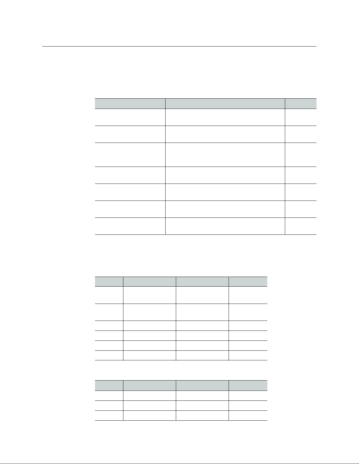
The following tables show examples of slot distributions for typical Kaleido-Modular-X
configurations. (In these examples, the output cards have a double rear connector
panel. A Densité
3+ FR1 frame can house up to 4 output cards with single rear panels.)
Card Description Rear panel
KMX-3901-IN-8-D 8-input HD/SD-SDI and 3 Gbps input module
with dual FlexBridge outputs
3 slots
KMX-3901-IN-16-D 16-input HD/SD-SDI and 3 Gbps input module
with dual FlexBridge outputs
4 slots
KMX-3901-IN-16-Q 16-input HD/SD-SDI and 3 Gbps input module
with quad FlexBridge outputs (convertible to a
4K UHD prescaler)
5 slots
KMX-3901-OUT-S (with
KMX-3901-OUT-D-3DRP)
Single-head output module, with double rear
connector panel
2 slots
KMX-3901-OUT-S (with
KMX-3901-OUT-D-3+SRP)
Single-head output module, with single rear
connector panel
1 slot
KMX-3901-OUT-D (with
KMX-3901-OUT-D-3DRP)
Dual-head output module, with double rear
connector panel
2 slots
KMX-3901-OUT-D (with
KMX-3901-OUT-D-3+SRP)
Dual-head output module, with single rear
connector panel
1 slot
64 × 4 in two separate housing frames
Card Model Rear panel covers... Insert card at...
Output A KMX-3901-OUT-D Slots 1–2 (e.g., in
Densité
3+ FR1)
Slot 1
Output B KMX-3901-OUT-D Slots 3–4 (e.g., in
Densité
3+ FR1)
Slot 3
Input A KMX-3901-IN-16-Q Slots 1–5 Slot 3
Input B KMX-3901-IN-16-Q Slots 6–10 Slot 8
Input C KMX-3901-IN-16-Q Slots 11–15 Slot 13
Input D KMX-3901-IN-16-Q Slots 16–20 Slot 18
64 × 2
Card Model Rear panel covers... Insert card at...
Output A KMX-3901-OUT-D Slots 1–2 Slot 1
Input A KMX-3901-IN-16-D Slots 3–6 Slot 5
Input B KMX-3901-IN-16-D Slots 7–10 Slot 9

7
Kaleido-Modular-X
Quick Start Guide
Input C KMX-3901-IN-16-D Slots 11–14 Slot 13
Input D KMX-3901-IN-16-D Slots 15–18 Slot 17
48 × 4
Card Model Rear panel covers... Insert card at...
Output B KMX-3901-OUT-D Slots 2–3 Slot 2
Output A KMX-3901-OUT-D Slots 4–5 Slot 4
Input A KMX-3901-IN-16-Q Slots 6–10 Slot 8
Input B KMX-3901-IN-16-Q Slots 11–15 Slot 13
Input C KMX-3901-IN-16-Q Slots 16–20 Slot 18
48 × 2
Card Model Rear panel covers... Insert card at...
Output A KMX-3901-OUT-D Slots 1–2 Slot 1
Input A KMX-3901-IN-16-D Slots 3–6 Slot 5
Input B KMX-3901-IN-16-D Slots 7–10 Slot 9
Input C KMX-3901-IN-16-D Slots 11–14 Slot 13
32 × 4
Card Model Rear panel covers... Insert card at...
Output B KMX-3901-OUT-D Slots 2–3 Slot 2
Output A KMX-3901-OUT-D Slots 4–5 Slot 4
Input A KMX-3901-IN-16-Q Slots 6–10 Slot 8
Input B KMX-3901-IN-16-Q Slots 11–15 Slot 13
32 × 2
Card Model Rear panel covers... Insert card at...
Output A KMX-3901-OUT-D Slots 1–2 Slot 1
Input A KMX-3901-IN-16-D Slots 3–6 Slot 5
Input B KMX-3901-IN-16-D Slots 7–10 Slot 9
64 × 2 (continued)
Card Model Rear panel covers... Insert card at...

8
Setting Up Your Kaleido-Modular-X System
Physical Setup
3 Remove the blank rear panels that cover the slots where you wish to install your cards,
by releasing their captive screws.
4 Position the new rear panels, and secure them in place with the captive screws at the
bottom (or on the right, in the case of a Densité
3+ FR1 frame).
5 Slide each of your new input and output cards into the appropriate slot (refer to the
table matching your intended configuration, above, if needed), and push gently on the
handle to seat the connectors. Seating an input card requires more pressure.
6 Verify that each card is securely seated in its slot, and leave the frame door open so that
you can monitor all the card’s LEDs.
24 × 2
Card Model Rear panel covers... Insert card at...
Output A KMX-3901-OUT-D Slots 2–3 Slot 2
Input A KMX-3901-IN-16-D Slots 4–7 Slot 6
Input B KMX-3901-IN-8-D Slots 8–10 Slot 9
16 × 4
Card Model Rear panel covers... Insert card at...
Output B KMX-3901-OUT-D Slots 2–3 Slot 2
Output A KMX-3901-OUT-D Slots 4–5 Slot 4
Input A KMX-3901-IN-16-Q Slots 6–10 Slot 8
16 × 2, 16 × 1
Card Model Rear panel covers... Insert card at...
Output A KMX-3901-OUT-D Slots 1–2 Slot 1
Input A KMX-3901-IN-16-D Slots 3–6 Slot 5
8 × 2, 8 × 1
Card Model Rear panel covers... Insert card at...
Output A KMX-3901-OUT-D Slots 2–3 Slot 2
Input A KMX-3901-IN-8-D Slots 4–6 Slot 5
IMPORTANT
• If you need to replace or momentarily remove a rear panel, make sure to
first remove the corresponding card itself from its slot (see Replacing Cards,
in the Kaleido-Modular-X Hardware Description & Installation Manual).
• Removing more than one input card at a time from a Kaleido-Modular-X
system in operation is not supported.
9
Kaleido-Modular-X
Quick Start Guide
7 Make the physical connections between your input and output cards, by using the
FlexBridge cables that shipped with your system. See
Bridging the Input and Output
Cards in a Kaleido-Modular-X, on page 13.
8 Power up the frame, if it was not in operation already.
Once the networking parameters are correctly configured on your Kaleido-Modular-X
output cards, it will not be necessary to switch off the housing frame’s power when
installing or removing cards.
The Kaleido-Modular-X system starts up. The startup sequence takes approximately
four minutes, during which time every card’s status LED is blinking orange.
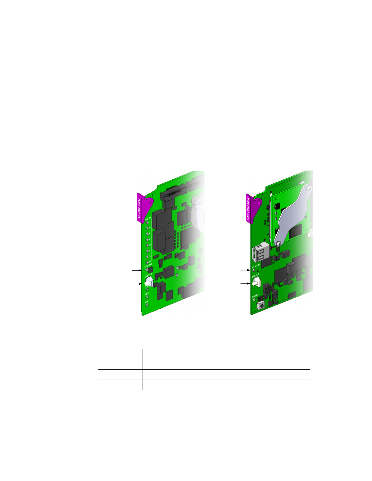
Once the startup has completed, the status LEDs on the output cards should be red
(steady) because the cards are not connected to the network yet:
9 If your system includes KMX-3901-IN-16-Q input cards to be used as 4K UHD prescalers,
connect their FlexBridge outputs A1 and B1 to the 3G/HD SDI inputs you wish to use
for your 4K monitoring purposes, at the rear of a KMX-3901 input card, and then see
Converting a KMX-3901-IN-16-Q Input Card to a 4K UHD Prescaler, on page 20, to
enable these cards’ prescaler mode.
Note: For more information on the card’s LEDs, refer to the Kaleido-
Modular-X Hardware Description & Installation Manual, available on the DVD
that shipped with your system.
Green Normal
Blinking orange Booting (or the card is selected for local control)
Red Firmware initialization in progress / no Ethernet / SD card error
Blinking red Fan failure / no rear / duplicate IP address
Select button
Status LED
Select button
Status LED
Front edge of a KMX-3901 input card Front edge of a KMX-3901 output card

10
Setting Up Your Kaleido-Modular-X System
Physical Setup
Example: 4K UHD prescaler’s FlexBridge outputs A1 and B1, connected to
3G/HD SDI inputs 5 and 6, at the rear of a KMX-3901-IN-16-D input card
10 Connect the Kaleido-RCP2 and the Audio Bridge Terminal (if available) to a dedicated
100Base-T Ethernet switch. You can also connect a mouse and a keyboard to your
Kaleido-RCP2.
Kaleido-Modular-X output cards automatically detects the resolution of any connected
display. If the required information is not available, then a fall-back resolution of
1920
× 1080 @ 60 Hz (HDTV) is used.
Notes
• The Kaleido-RCP2, and Audio Bridge Terminal (ABT) are optional devices,
and may not have been shipped with your Kaleido-Modular-X system. For
information on these and other Kaleido -Modular-X options, please contact
your Grass Valley sales representative.
• You may need to upgrade your Audio Bridge Terminal and Kaleido-RCP2
devices (if available) to the latest firmware. The update files can be found
on the DVD that shipped with your multiviewer, and on Grass Valley’s
support portal. Please refer to the Kaleido-RCP2 Guide to Installation and
Operation, and to the Audio Bridge Terminal Guide to Installation and
Operation (available on the DVD, and from the portal) for instructions on
how to determine the firmware level, and how to perform the upgrade for
these devices.
• The Kaleido-Modular-X supports one ABT device. With a 3RU model, you
can achieve redundancy by connecting the ABT to more than one input
card, in which case the Kaleido-Modular-X system uses the signal from the
input card that is the farthest from the output cards (i.e., Input
D, if you
have 4 input cards, Input
C if you have 3 input cards, Input B if you have 2
input cards).
11
Kaleido-Modular-X
Quick Start Guide
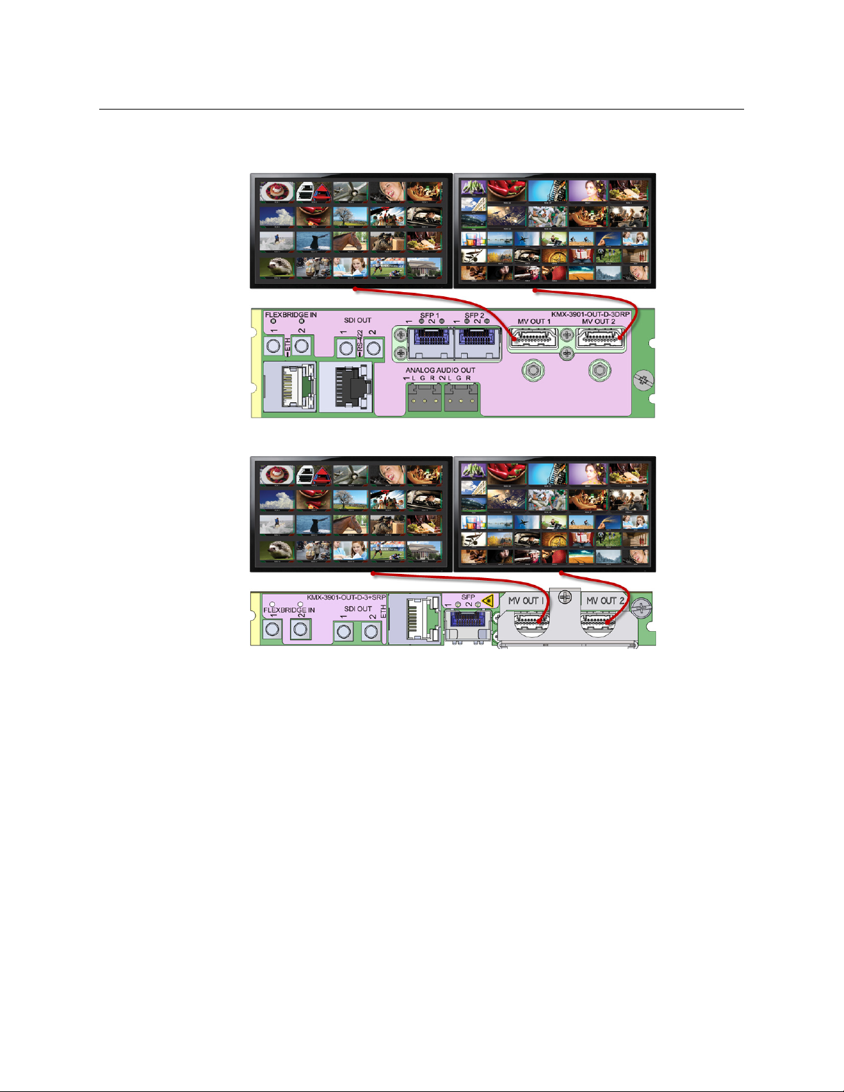
11 Connect your Kaleido-Modular-X output cards to displays that support this resolution.
• Monitor wall displays: Connect the output cards’ MV OUT outputs to the displays.
HDMI outputs on double rear module, connected to displays
HDMI outputs on single rear module, connected to displays
• Quad-link 4K UHD output:
• Four 1080p displays—In the case of a quad-head system meant to output a 4K
UHD signal to four 1080p displays, connect the output cards’ SDI monitoring
outputs to the displays, referring to the table below for proper mapping.
• One 4K UHD display—If your system is meant to output to a single 4K UHD
display, connect the output cards’ SDI monitoring outputs to the display, using
an SDI-to-HDMI converter, if needed. Refer to the table below for proper
mapping.
The SDI outputs are mapped as follows. This configuration does not support
rotated displays. Refer to Creating a 4K UHD Room, and to 4K UHD Spanning, in the
12
Setting Up Your Kaleido-Modular-X System
Physical Setup
Kaleido-X User’s Manual, for instructions on how to create 4K UHD rooms and
layouts.
• Broadcast monitors: If your installation involves broadcast monitors, connect
them to the appropriate SDI outputs. It is also possible to connect SDI outputs to a
router. Refer to Configuring the HD-SDI Monitoring Output Format, in the Kaleido-X
User’s Manual, for instructions on setting the scan format.
If you wish to use a different resolution, see Changing the Output Resolution, on
page 19, for detailed instructions.
12 Connect one or more video sources to the Kaleido-Modular-X input cards.
13 If you have configured 4K UHD prescaler cards (at step 9, above), connect one or two
quad link 3G-SDI signal sources to each prescaler card, as follows:
14 If your system configuration involves M3 cables, connect them between the
appropriate output modules on the router side, and the KMX-3901-IN-M3 rear modules
on the multiviewer side.
OUTPUT A,
SDI OUT 1
Top l e f t
quadrant
OUTPUT B,
SDI OUT 1
Top r i ght
quadrant
OUTPUT A,
SDI OUT 2
Bottom left
quadrant
OUTPUT B,
SDI OUT 2
Bottom right
quadrant
IMPORTANT
Within a Kaleido-Modular-X system, all output heads must be configured
with the same refresh rate. If your system is referenced, then the heads’
refresh rate must also match the reference signal's refresh rate.
Description Connector
Link 1A – Top left quadrant of 4K UHD signal A 3G/HD/SD IN 1
Link 2A – Top right quadrant of 4K UHD signal A 3G/HD/SD IN 2
Link 3A – Bottom left quadrant of 4K UHD signal A 3G/HD/SD IN 9
Link 4A – Bottom right quadrant of 4K UHD signal A 3G/HD/SD IN 10
Link 1B – Top left quadrant of 4K UHD signal B 3G/HD/SD IN 5
Link 2B – Top right quadrant of 4K UHD signal B 3G/HD/SD IN 6
Link 3B – Bottom left quadrant of 4K UHD signal B 3G/HD/SD IN 13
Link 4B – Bottom right quadrant of 4K UHD signal B 3G/HD/SD IN 14
IMPORTANT
The 4K UHD prescaler card and its 4K UHD source signals must be
referenced together.
Loading...