


NV915
QuickStart Guide
Product Number: QG0007-02 Revision: A0; Date: 4/25/13 1
NV915 system controller
and Accessories
NV915 Product Summary
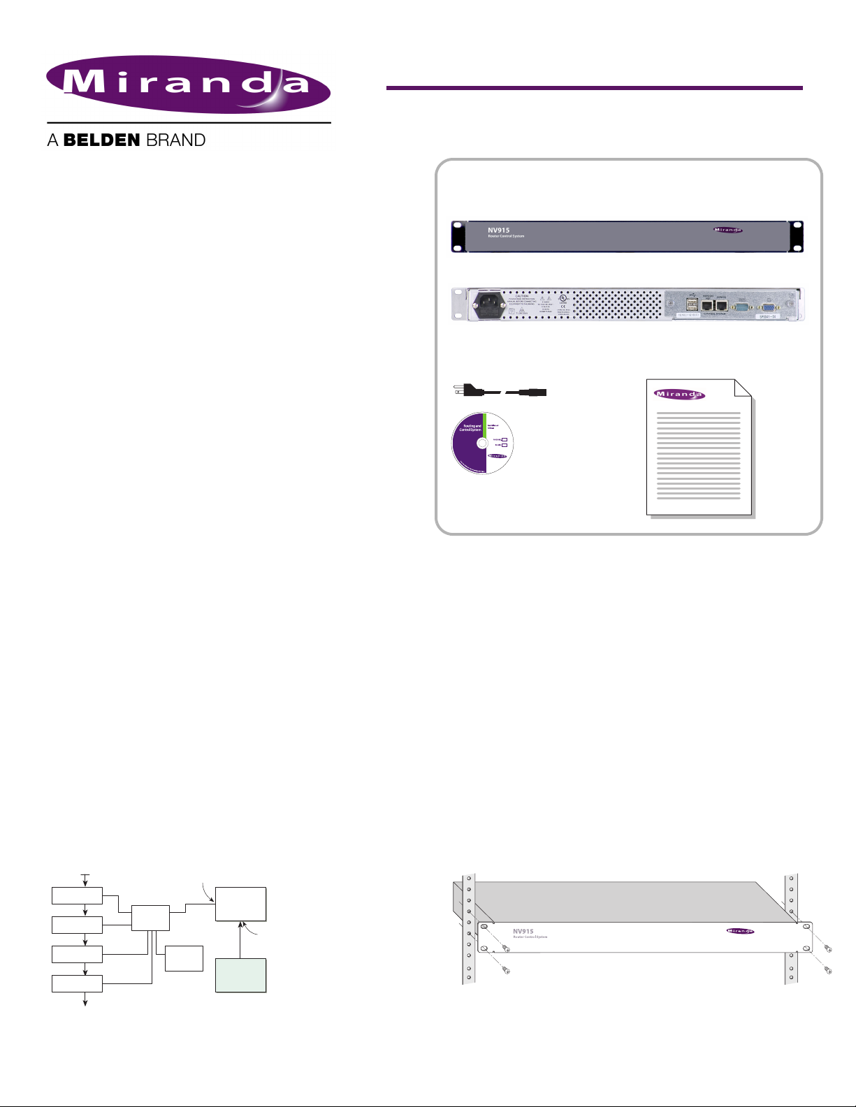
Your Miranda shipment contains an NV915 system control-
ler, power cords, and this Quick Start guide. Depending on
you order options, the shipment might also include cables
and peripheral devices. See Figure 1.
An NV9000 router control system allows you to configure
and operate routers, control panels, and other connected
equipment. The NV9000 control system includes several
parts that work together:
• NV915 system controller.
• NV9000-SE Utilities configuration software.
• PCs running configuration or control software.
• Routers.
• Control panels (physical or virtual).
• Optionally, master control components.
• Optionally, automation, UMD, and other subsystems.
The NV915 system controller’s features include:
• Two Ethernet ports, one for routers and panels, and the
other for configuration.
• Two USB ports, a COM port and a monitor port.
• Flash-based storage.
• Support for up to 32 NV96xx control panels.
• Support for up to 4 NVISION series routers.
• Small size: 1RU, 9″ deep.
NV9000-SE Utilities
NV9000-SE Utilities (NV9000-SE Utilities, for short) is the
“next g ener atio n config urat ion t ool” to be used wit h NV90 00
routing control systems.
You can use it, connected to the NV915 system controller, to
create and upload configurations. You can use it, detached
from the NV915, to create configuration files.
NV9000-SE Utilities is designed to model, as closely as possi-
ble, the user’s tasks and facility structure. It leads the user
through the process of configuring a router control system.
NV9000-SE Utilities fits in the NV9000 scheme like this:
Figure 1. System Block Diagram
Installation
To prepare the NV915 system controller for use, you must take
these two steps:
• Install the NV915 hardware.
• Install the NV9000-SE Utilities software on a PC.
To run the NV9000-SE Utilities, you will need a PC that
supports Java 1.5 or later.
Installing the NV915
Perform the steps that follow to install the NV915.
Rack Mounting
S Because the NV915 is small, you might not have enough space to
reach behind it to make connections. In that case, leave this step
until last.
Place the NV915 in the rack where you want it, aligning the
screw holes with holes in your rack frame. Secure the router
using your screws, nuts, and washers.
The mounting holes are spaced 1.25″ (31mm) vertically and
allow approximately 1/8″ (3mm) of play horizontally.
Router
Ethernet
Switch
NV 915
Control
Panel
NV9000-SE
Utilities
Router
Router
Router
NVISION Network Port
Video Ref.
Config Port
On
Client
PC
(front view)
Figure 1. Package Contents
Quick-Start Guide
(this document)
1 software and
documentation disk
(rear view)
AC power cord(s)
NV915(s)
2 Product Number: QG0007-02 Revision: A0; Date: 4/25/13
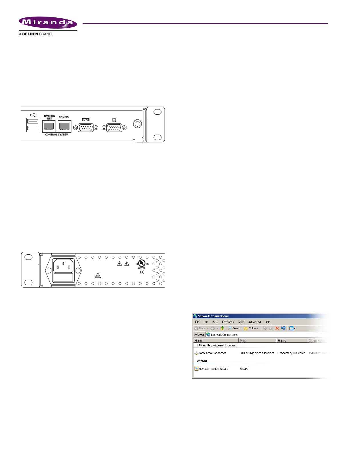
Ethernet Cable
Connect an Ethernet cable (RJ-45) to the “NVISION Net”
port. (See Figure 1.) Connect the other end of that cable to an
Ethernet switch. Connect your routers and control panels to
the Ethernet switch.
Connect an Ethernet cable to the “Config” port. Connect the
other end of that cable to the Ethernet switch. Connect the
Ethernet port of the computer you intend to use for configu-
ration to the switch.
Figure 1. Ethernet Connectors
S Alternatively, use a crossover cable between the Config port and
your PC’s Ethernet port.
You will have to add the “Config” port address to your PC’s
network addresses. You will have to add the NV915 system
controller to NV9000-SE Utilities on your configuration
PC(s). See Configuration.
Power and Ground
The NV915 accepts “universal” power: 90–130/180–250VAC,
50/60Hz, at 0.5/0.3A, with a 30W maximum. Simply plug
the AC cord into a main socket and into the power socket at
the rear of the unit. (There is no on-off switch.) There is no
special grounding requirement.
Installing NV9000-SE Utilities
Insert the Software and Documentation CD (SB0033-xx) in
your CD drive. The CD will auto-play. Click ‘Configuration
Software’ in the main window. A new window appears. Then
cllick ‘Install NV9000-SE Utilities’. The installer will launch.
When you see the first instruction screen, follow the simple
instructions, clicking ‘Next’ as required. The entire installa-
tion takes less than a minute.
(Under Windows)
The default pathname of the NV9000-SE Utilities executable
is:
C:\Program Files\NVISION\NV9000-SE Utilities\
NV9000-SE Utilities.exe.
(You can specify a different pathname during installation.) If
you elect to add the program to the Start menu, its “path” is
Start > Programs > NVISION > NV9000-SE Utilities >
NV9000-SE Utilities
The default pathname of configuration file storage is:
C:\Documents and Settings\current user\CtrlSysConfigs\
where “current user” is a user’s login ID on the PC. Note: SE
creates this folder at its first launch. It is not created at instal-
lation. SE will create one such folder for each user that logs in
and runs SE.
That folder contains subfolders holding configuration data.
The subfolder names are the configuration names. The folder
‘ControlSysDB’ is a prototype containing the default configu-
ration and, in fact, when NV9000-SE Utilities launches for
the first time, it opens this configuration. This configuration
is essentially “empty.”
S We recommend that you create a desktop icon for the software.
Configuration
These are the default IP addresses of the NV915’s Ethernet
ports:
• “Config” port — 192.168.97.1
• “Network” port — 192.168.2.1
(You can change these addresses.)
After you have installed the NV915 and NV9000-SE Utilities,
two steps are required to get your system running.
• Place your PC on the NV915’s Config network.
• Add the Config port to NV9000-SE Utilities.
Config Port
Follow these steps to add your PC to the Config network:
1) Launch ‘Settings>Network Configuration’ from you PC’s
Start menu. The following window appears:
VIDEO/AUDIO
PROFESSIONAL
CNTRL NO. 9K50
E146905
90-130/180-250V~
0.5A/0.3A
50/60Hz
30 WATTS MAX
CAUTION
PLEASE READ INSTRUCTION
MANUAL BEFORE CONNECTING
EQUIPMENT TO THE MAINS
T1.0A 250V
 Loading...