


 Loading...
NV9605
NV9000 Control Panel
User’s Guide
UG0043-01
14 Nov 2014

Copyright & Trademark Notice
Copyright © 2014 Miranda. All rights reserved.
Belden, Belden Sending All The Right Signals, and the Belden logo are trademarks or registered trademarks of Belden Inc. or its affiliated companies in the United States and other jurisdictions. Miranda, NVISION, NV9000, NV9000-SE Utilities, and NV9605 are trademarks or registered trademarks of Miranda. Belden Inc., Miranda, and other parties may also have trademark rights in other terms used herein.
Terms and Conditions
Please read the following terms and conditions carefully. By using NV9605 documentation, you agree to the following terms and conditions.
Miranda hereby grants permission and license to owners of NV9605 routers to use their product manuals for their own internal business use. Manuals for Miranda products may not be reproduced or transmitted in any form or by any means, electronic or mechanical, including photocopying and recording, for any purpose unless specifically authorized in writing by Miranda.
A Miranda manual may have been revised to reflect changes made to the product during its manufacturing life. Thus, different versions of a manual may exist for any given product. Care should be taken to ensure that one obtains the proper manual version for a specific product serial number.
Information in this document is subject to change without notice and does not represent a commitment on the part of Miranda.
Warranty information is available in the support section of the Miranda web site (www.grassvalley.com).
Title |
NV9605 User’s Guide |
Part Number |
UG0043-01 |
Revision |
1.1 (14 Nov 14) |
ii

NV9605
User’s Guide
Change History
Rev. |
Date |
ECO |
Description |
Approved |
|
|
|
|
|
1.0 |
05 Nov 10 |
17286 |
Initial release. |
D. Cox |
|
|
|
|
|
1.1 |
14 Nov 14 |
19357 |
Reformatted. |
D.Cox |
|
|
|
|
|
Safety Compliance
 FCC Statement
This equipment has been tested and found to comply with the limits for a Class A digital device, pursuant to part 15 of the FCC Rules. These limits are designed to provide reasonable protection against harmful interference when the equipment is operated in a commercial environment. This equipment generates, uses, and can radiate radio frequency energy and, if not installed and used in accordance with the instruction manual, may cause harmful interference to radio communications. Operation of this equipment in a residential area is likely to cause harmful interference in which case the user will be required to correct the interference at his own expense.

 Declaration of Conformance (CE)
All of the equipment described in this manual has been designed to conform with the required safety and emissions standards of the European Community. Products tested and verified to meet these standards are marked as required by law with the CE mark.
When shipped into member countries of the European Community, this equipment is accompanied by authentic copies of original Declarations of Conformance on file in the Miranda GVD offices in Grass Valley, California USA.
Software License Agreement and Warranty Information
Contact Miranda for details on the software license agreement and product warranty.
Important Safeguards and Notices
This section provides important safety guidelines for operators and service personnel. Specific warnings and cautions appear throughout the manual where they apply. Please read and follow this important information, especially those instructions related to the risk of electric shock or injury to persons.
WARNING
Any instructions in this manual that require opening the equipment cover or enclosure are for use by qualified service personnel only. To reduce the risk of electric shock, do not perform any service other than that contained in the operating instructions unless you are qualified to do so.
iii
Restriction on Hazardous Substances (RoHs)
Miranda is in compliance with EU Directive RoHS 2002/95/EC governing the restricted use of certain hazardous substances and materials in products and in our manufacturing processes.
Miranda has a substantial program in place for RoHS compliance that includes significant investment in our manufacturing process, and a migration of Miranda product electronic components and structural materials to RoHS compliance.
It is our objective at Miranda GVD to maintain compliance with all relevant environmental and product regulatory requirements. Detailed information on specific products or on the RoHS program at Miranda is available from Miranda Customer Support at
1-800-719-1900 (toll-free) or 1-530-265-1000 (outside the U.S.).
Symbols and Their Meanings
The lightning flash with arrowhead symbol within an equilateral triangle alerts the user to the presence of dangerous voltages within the product’s enclosure that may be of sufficient magnitude to constitute a risk of electric shock to persons.
The exclamation point within an equilateral triangle alerts the user to the presence of important operating and maintenance/service instructions.
The Ground symbol represents a protective grounding terminal. Such a terminal must be connected to earth ground prior to making any other connections to the equipment.
The fuse symbol indicates that the fuse referenced in the text must be replaced with one having the ratings indicated.
The presence of this symbol in or on Miranda equipment means that it has been designed, tested and certified as complying with applicable Underwriter’s Laboratory (USA) regulations and recommendations.
The presence of this symbol in or on Miranda equipment means that it has been designed, tested and certified as essentially complying with all applicable European Union (CE) regulations and recommendations.
iv

NV9605
User’s Guide
General Warnings
A warning indicates a possible hazard to personnel which may cause injury or death. Observe the following general warnings when using or working on this equipment:
•Heed all warnings on the unit and in the operating instructions.
•Do not use this equipment in or near water.
•This equipment is grounded through the grounding conductor of the power cord. To avoid electrical shock, plug the power cord into a properly wired receptacle before connecting the equipment inputs or outputs.
•Route power cords and other cables so they are not likely to be damaged.
•Disconnect power before cleaning the equipment. Do not use liquid or aerosol cleaners; use only a damp cloth.
•Dangerous voltages may exist at several points in this equipment. To avoid injury, do not touch exposed connections and components while power is on.
•Do not wear rings or wristwatches when troubleshooting high current circuits such as the power supplies.
•To avoid fire hazard, use only the specified fuse(s) with the correct type number, voltage and current ratings as referenced in the appropriate locations in the service instructions or on the equipment. Always refer fuse replacements to qualified service personnel.
•To avoid explosion, do not operate this equipment in an explosive atmosphere.
•Have qualified service personnel perform safety checks after any service.
General Cautions
A caution indicates a possible hazard to equipment that could result in equipment damage. Observe the following cautions when operating or working on this equipment:
•When installing this equipment, do not attach the power cord to building surfaces.
•To prevent damage to equipment when replacing fuses, locate and correct the problem that caused the fuse to blow before re-applying power.
•Use only the specified replacement parts.
•Follow static precautions at all times when handling this equipment.
•This product should only be powered as described in the manual. To prevent equipment damage, select the proper line voltage on the power supply(ies) as described in the installation documentation.
•To prevent damage to the equipment, read the instructions in the equipment manual for proper input voltage range selection.
•Some products include a backup battery. There is a risk of explosion if the battery is replaced by a battery of an incorrect type. Dispose of batteries according to instructions.
•Products that have (1) no on/off switch and (2) use an external power supply must be installed in proximity to a main power outlet that is easily accessible.
•To reduce the risk of electrical shock, plug each power supply cord into a separate branch circuit having a separate service ground.
v

vi

Table of Contents
1 Preface . . . . . . . . . . . . . . . . . . . . . . . . . . . . . . . . . . . . . . . . . . . . . . . . 1
Chapter Structure . . . . . . . . . . . . . . . . . . . . . . . . . . . . . . . . . . . . . . . . . . . . . . . . . . . . . . . . . . . . . . . . . . . . . . . . . . . . . . |
1 |
The PDF Document . . . . . . . . . . . . . . . . . . . . . . . . . . . . . . . . . . . . . . . . . . . . . . . . . . . . . . . . . . . . . . . . . . . . . . . . . . . . . |
1 |
Terms, Conventions and Abbreviations . . . . . . . . . . . . . . . . . . . . . . . . . . . . . . . . . . . . . . . . . . . . . . . . . . . . . . . . . . |
2 |
Other Documentation and Software . . . . . . . . . . . . . . . . . . . . . . . . . . . . . . . . . . . . . . . . . . . . . . . . . . . . . . . . . . . . |
2 |
2 Introduction . . . . . . . . . . . . . . . . . . . . . . . . . . . . . . . . . . . . . . . . . . . 3
Summary . . . . . . . . . . . . . . . . . . . . . . . . . . . . . . . . . . . . . . . . . . . . . . . . . . . . . . . . . . . . . . . . . . . . . . . . . . . . . . . . . . . . . . . 3
Panel Organization . . . . . . . . . . . . . . . . . . . . . . . . . . . . . . . . . . . . . . . . . . . . . . . . . . . . . . . . . . . . . . . . . . . . . . . . . . . . . 4
Function Buttons. . . . . . . . . . . . . . . . . . . . . . . . . . . . . . . . . . . . . . . . . . . . . . . . . . . . . . . . . . . . . . . . . . . . . . . . . . . 4
Differences between the Left and Right Function Buttons. . . . . . . . . . . . . . . . . . . . . . . . . . . . . . . 4
Alphanumeric Display . . . . . . . . . . . . . . . . . . . . . . . . . . . . . . . . . . . . . . . . . . . . . . . . . . . . . . . . . . . . . . . . . . . . . . 5
Display Fields . . . . . . . . . . . . . . . . . . . . . . . . . . . . . . . . . . . . . . . . . . . . . . . . . . . . . . . . . . . . . . . . . . . . . . . . . 5
Flags . . . . . . . . . . . . . . . . . . . . . . . . . . . . . . . . . . . . . . . . . . . . . . . . . . . . . . . . . . . . . . . . . . . . . . . . . . . . . . . . . . 5
Modes of Operation . . . . . . . . . . . . . . . . . . . . . . . . . . . . . . . . . . . . . . . . . . . . . . . . . . . . . . . . . . . . . . . . . . . . . . . . . . . . 5
Limited X-Y Mode . . . . . . . . . . . . . . . . . . . . . . . . . . . . . . . . . . . . . . . . . . . . . . . . . . . . . . . . . . . . . . . . . . . . . . . . . . 6
Multi-Destination Mode . . . . . . . . . . . . . . . . . . . . . . . . . . . . . . . . . . . . . . . . . . . . . . . . . . . . . . . . . . . . . . . . . . . . 6
Secondary Modes . . . . . . . . . . . . . . . . . . . . . . . . . . . . . . . . . . . . . . . . . . . . . . . . . . . . . . . . . . . . . . . . . . . . . . . . . . 6
Other NV9605 Functions . . . . . . . . . . . . . . . . . . . . . . . . . . . . . . . . . . . . . . . . . . . . . . . . . . . . . . . . . . . . . . . . . . . . . . . . 6
3 Installation. . . . . . . . . . . . . . . . . . . . . . . . . . . . . . . . . . . . . . . . . . . . . 7
Package Contents . . . . . . . . . . . . . . . . . . . . . . . . . . . . . . . . . . . . . . . . . . . . . . . . . . . . . . . . . . . . . . . . . . . . . . . . . . . . . . 7
Installation . . . . . . . . . . . . . . . . . . . . . . . . . . . . . . . . . . . . . . . . . . . . . . . . . . . . . . . . . . . . . . . . . . . . . . . . . . . . . . . . . . . . . 7
Installing Software and Documentation. . . . . . . . . . . . . . . . . . . . . . . . . . . . . . . . . . . . . . . . . . . . . . . . . . . . . . . . . . 8
Initialization . . . . . . . . . . . . . . . . . . . . . . . . . . . . . . . . . . . . . . . . . . . . . . . . . . . . . . . . . . . . . . . . . . . . . . . . . . . . . . . . . . . . 8
Testing . . . . . . . . . . . . . . . . . . . . . . . . . . . . . . . . . . . . . . . . . . . . . . . . . . . . . . . . . . . . . . . . . . . . . . . . . . . . . . . . . . . . . . . . . 9
4 Configuration . . . . . . . . . . . . . . . . . . . . . . . . . . . . . . . . . . . . . . . . . 11
Summary . . . . . . . . . . . . . . . . . . . . . . . . . . . . . . . . . . . . . . . . . . . . . . . . . . . . . . . . . . . . . . . . . . . . . . . . . . . . . . . . . . . . . . 11 Adding a Panel to an NV9000 Configuration . . . . . . . . . . . . . . . . . . . . . . . . . . . . . . . . . . . . . . . . . . . . . . . . . . . . 11 NV9605 Panel Configuration Page . . . . . . . . . . . . . . . . . . . . . . . . . . . . . . . . . . . . . . . . . . . . . . . . . . . . . . . . . . . . . . 14 Regions of the Configuration Page. . . . . . . . . . . . . . . . . . . . . . . . . . . . . . . . . . . . . . . . . . . . . . . . . . . . . . . . . 14 Configuration Tasks . . . . . . . . . . . . . . . . . . . . . . . . . . . . . . . . . . . . . . . . . . . . . . . . . . . . . . . . . . . . . . . . . . . . . . . 15 Pages . . . . . . . . . . . . . . . . . . . . . . . . . . . . . . . . . . . . . . . . . . . . . . . . . . . . . . . . . . . . . . . . . . . . . . . . . . . . . . . . . . . . . . . . . 15 Commitment Buttons . . . . . . . . . . . . . . . . . . . . . . . . . . . . . . . . . . . . . . . . . . . . . . . . . . . . . . . . . . . . . . . . . . . . . . . . . 15 Panel Options. . . . . . . . . . . . . . . . . . . . . . . . . . . . . . . . . . . . . . . . . . . . . . . . . . . . . . . . . . . . . . . . . . . . . . . . . . . . . . . . . . 16 Checkbox Options . . . . . . . . . . . . . . . . . . . . . . . . . . . . . . . . . . . . . . . . . . . . . . . . . . . . . . . . . . . . . . . . . . . . . . . . 17 Button Definitions . . . . . . . . . . . . . . . . . . . . . . . . . . . . . . . . . . . . . . . . . . . . . . . . . . . . . . . . . . . . . . . . . . . . . . . . . . . . . 18 Button Specification. . . . . . . . . . . . . . . . . . . . . . . . . . . . . . . . . . . . . . . . . . . . . . . . . . . . . . . . . . . . . . . . . . . . . . . 18 Button Types . . . . . . . . . . . . . . . . . . . . . . . . . . . . . . . . . . . . . . . . . . . . . . . . . . . . . . . . . . . . . . . . . . . . . . . . . . . . . 19 Multi-Destination Configuration . . . . . . . . . . . . . . . . . . . . . . . . . . . . . . . . . . . . . . . . . . . . . . . . . . . . . . . . . . . . . . . 23 Single-Destination Configuration . . . . . . . . . . . . . . . . . . . . . . . . . . . . . . . . . . . . . . . . . . . . . . . . . . . . . . . . . . . . . . 24
vii

Table of Contents
5 Operation. . . . . . . . . . . . . . . . . . . . . . . . . . . . . . . . . . . . . . . . . . . . . 25
Summary . . . . . . . . . . . . . . . . . . . . . . . . . . . . . . . . . . . . . . . . . . . . . . . . . . . . . . . . . . . . . . . . . . . . . . . . . . . . . . . . . . . . . . |
25 |
Modes of Operation . . . . . . . . . . . . . . . . . . . . . . . . . . . . . . . . . . . . . . . . . . . . . . . . . . . . . . . . . . . . . . . . . . . . . . |
25 |
Limited X-Y Mode . . . . . . . . . . . . . . . . . . . . . . . . . . . . . . . . . . . . . . . . . . . . . . . . . . . . . . . . . . . . . . . . . . . . |
26 |
Multi-Destination Mode . . . . . . . . . . . . . . . . . . . . . . . . . . . . . . . . . . . . . . . . . . . . . . . . . . . . . . . . . . . . . . |
26 |
Single-Destination Operation . . . . . . . . . . . . . . . . . . . . . . . . . . . . . . . . . . . . . . . . . . . . . . . . . . . . . . . . |
26 |
Secondary Modes . . . . . . . . . . . . . . . . . . . . . . . . . . . . . . . . . . . . . . . . . . . . . . . . . . . . . . . . . . . . . . . . . . . . . . . . . |
26 |
Button Legends . . . . . . . . . . . . . . . . . . . . . . . . . . . . . . . . . . . . . . . . . . . . . . . . . . . . . . . . . . . . . . . . . . . . . . . . . . . |
27 |
Operating Concepts. . . . . . . . . . . . . . . . . . . . . . . . . . . . . . . . . . . . . . . . . . . . . . . . . . . . . . . . . . . . . . . . . . . . . . . . . . . . |
27 |
Pages . . . . . . . . . . . . . . . . . . . . . . . . . . . . . . . . . . . . . . . . . . . . . . . . . . . . . . . . . . . . . . . . . . . . . . . . . . . . . . . . . . . . |
27 |
Source Shift . . . . . . . . . . . . . . . . . . . . . . . . . . . . . . . . . . . . . . . . . . . . . . . . . . . . . . . . . . . . . . . . . . . . . . . . . . . . . . |
27 |
Levels . . . . . . . . . . . . . . . . . . . . . . . . . . . . . . . . . . . . . . . . . . . . . . . . . . . . . . . . . . . . . . . . . . . . . . . . . . . . . . . . . . . . |
28 |
Breakaway . . . . . . . . . . . . . . . . . . . . . . . . . . . . . . . . . . . . . . . . . . . . . . . . . . . . . . . . . . . . . . . . . . . . . . . . . . . |
28 |
Hold . . . . . . . . . . . . . . . . . . . . . . . . . . . . . . . . . . . . . . . . . . . . . . . . . . . . . . . . . . . . . . . . . . . . . . . . . . . . . . . . . . . . . . |
28 |
Breakaway . . . . . . . . . . . . . . . . . . . . . . . . . . . . . . . . . . . . . . . . . . . . . . . . . . . . . . . . . . . . . . . . . . . . . . . . . . . |
28 |
Gang Switching . . . . . . . . . . . . . . . . . . . . . . . . . . . . . . . . . . . . . . . . . . . . . . . . . . . . . . . . . . . . . . . . . . . . . . |
28 |
Buttons . . . . . . . . . . . . . . . . . . . . . . . . . . . . . . . . . . . . . . . . . . . . . . . . . . . . . . . . . . . . . . . . . . . . . . . . . . . . . . . . . . . |
29 |
Broadcast . . . . . . . . . . . . . . . . . . . . . . . . . . . . . . . . . . . . . . . . . . . . . . . . . . . . . . . . . . . . . . . . . . . . . . . . . . . . |
29 |
Chop . . . . . . . . . . . . . . . . . . . . . . . . . . . . . . . . . . . . . . . . . . . . . . . . . . . . . . . . . . . . . . . . . . . . . . . . . . . . . . . . |
30 |
Default State . . . . . . . . . . . . . . . . . . . . . . . . . . . . . . . . . . . . . . . . . . . . . . . . . . . . . . . . . . . . . . . . . . . . . . . . . |
30 |
Destination . . . . . . . . . . . . . . . . . . . . . . . . . . . . . . . . . . . . . . . . . . . . . . . . . . . . . . . . . . . . . . . . . . . . . . . . . . |
30 |
Destination Lock . . . . . . . . . . . . . . . . . . . . . . . . . . . . . . . . . . . . . . . . . . . . . . . . . . . . . . . . . . . . . . . . . . . . . |
30 |
Destination Protect . . . . . . . . . . . . . . . . . . . . . . . . . . . . . . . . . . . . . . . . . . . . . . . . . . . . . . . . . . . . . . . . . . |
30 |
Free Source . . . . . . . . . . . . . . . . . . . . . . . . . . . . . . . . . . . . . . . . . . . . . . . . . . . . . . . . . . . . . . . . . . . . . . . . . . |
31 |
Hold . . . . . . . . . . . . . . . . . . . . . . . . . . . . . . . . . . . . . . . . . . . . . . . . . . . . . . . . . . . . . . . . . . . . . . . . . . . . . . . . . |
31 |
Level . . . . . . . . . . . . . . . . . . . . . . . . . . . . . . . . . . . . . . . . . . . . . . . . . . . . . . . . . . . . . . . . . . . . . . . . . . . . . . . . |
31 |
Menu . . . . . . . . . . . . . . . . . . . . . . . . . . . . . . . . . . . . . . . . . . . . . . . . . . . . . . . . . . . . . . . . . . . . . . . . . . . . . . . . |
31 |
Name Set Toggle . . . . . . . . . . . . . . . . . . . . . . . . . . . . . . . . . . . . . . . . . . . . . . . . . . . . . . . . . . . . . . . . . . . . . |
32 |
None/All . . . . . . . . . . . . . . . . . . . . . . . . . . . . . . . . . . . . . . . . . . . . . . . . . . . . . . . . . . . . . . . . . . . . . . . . . . . . . |
32 |
Panel Lock . . . . . . . . . . . . . . . . . . . . . . . . . . . . . . . . . . . . . . . . . . . . . . . . . . . . . . . . . . . . . . . . . . . . . . . . . . . |
32 |
Previous Source . . . . . . . . . . . . . . . . . . . . . . . . . . . . . . . . . . . . . . . . . . . . . . . . . . . . . . . . . . . . . . . . . . . . . . |
32 |
Salvo . . . . . . . . . . . . . . . . . . . . . . . . . . . . . . . . . . . . . . . . . . . . . . . . . . . . . . . . . . . . . . . . . . . . . . . . . . . . . . . . |
32 |
Source . . . . . . . . . . . . . . . . . . . . . . . . . . . . . . . . . . . . . . . . . . . . . . . . . . . . . . . . . . . . . . . . . . . . . . . . . . . . . . . |
32 |
Source is Master . . . . . . . . . . . . . . . . . . . . . . . . . . . . . . . . . . . . . . . . . . . . . . . . . . . . . . . . . . . . . . . . . . . . . . |
32 |
Source Shift . . . . . . . . . . . . . . . . . . . . . . . . . . . . . . . . . . . . . . . . . . . . . . . . . . . . . . . . . . . . . . . . . . . . . . . . . . |
33 |
Undefined. . . . . . . . . . . . . . . . . . . . . . . . . . . . . . . . . . . . . . . . . . . . . . . . . . . . . . . . . . . . . . . . . . . . . . . . . . . . |
33 |
Lock, Protect, and Release . . . . . . . . . . . . . . . . . . . . . . . . . . . . . . . . . . . . . . . . . . . . . . . . . . . . . . . . . . . . . . . . . |
33 |
Locks and Protects with Breakaway . . . . . . . . . . . . . . . . . . . . . . . . . . . . . . . . . . . . . . . . . . . . . . . . . . . |
34 |
Takes . . . . . . . . . . . . . . . . . . . . . . . . . . . . . . . . . . . . . . . . . . . . . . . . . . . . . . . . . . . . . . . . . . . . . . . . . . . . . . . . . . . . . |
34 |
Case 1 — Limited X-Y Mode . . . . . . . . . . . . . . . . . . . . . . . . . . . . . . . . . . . . . . . . . . . . . . . . . . . . . . . . . . . |
34 |
Case 2 — Multi-Destination Mode . . . . . . . . . . . . . . . . . . . . . . . . . . . . . . . . . . . . . . . . . . . . . . . . . . . . . |
35 |
Multi-Destination Operations . . . . . . . . . . . . . . . . . . . . . . . . . . . . . . . . . . . . . . . . . . . . . . . . . . . . . . . . . . . . . |
35 |
Name Sets . . . . . . . . . . . . . . . . . . . . . . . . . . . . . . . . . . . . . . . . . . . . . . . . . . . . . . . . . . . . . . . . . . . . . . . . . . . . . . . . |
36 |
Broadcast Routes . . . . . . . . . . . . . . . . . . . . . . . . . . . . . . . . . . . . . . . . . . . . . . . . . . . . . . . . . . . . . . . . . . . . . . . . . |
36 |
Before You Begin . . . . . . . . . . . . . . . . . . . . . . . . . . . . . . . . . . . . . . . . . . . . . . . . . . . . . . . . . . . . . . . . . . . . . |
36 |
Performing a Broadcast Take — Limited X-Y Mode . . . . . . . . . . . . . . . . . . . . . . . . . . . . . . . . . . . . . |
37 |
Performing a Broadcast Take — Multi-Destination Mode . . . . . . . . . . . . . . . . . . . . . . . . . . . . . . . |
37 |
Important Points . . . . . . . . . . . . . . . . . . . . . . . . . . . . . . . . . . . . . . . . . . . . . . . . . . . . . . . . . . . . . . . . . . . . . |
37 |
Data Routing. . . . . . . . . . . . . . . . . . . . . . . . . . . . . . . . . . . . . . . . . . . . . . . . . . . . . . . . . . . . . . . . . . . . . . . . . . . . . . |
37 |
Automatic Data Routing . . . . . . . . . . . . . . . . . . . . . . . . . . . . . . . . . . . . . . . . . . . . . . . . . . . . . . . . . . . . . . |
38 |
Manual Data Routing . . . . . . . . . . . . . . . . . . . . . . . . . . . . . . . . . . . . . . . . . . . . . . . . . . . . . . . . . . . . . . . . . |
38 |
Semi-Automatic Data Routing . . . . . . . . . . . . . . . . . . . . . . . . . . . . . . . . . . . . . . . . . . . . . . . . . . . . . . . . |
38 |
Chop . . . . . . . . . . . . . . . . . . . . . . . . . . . . . . . . . . . . . . . . . . . . . . . . . . . . . . . . . . . . . . . . . . . . . . . . . . . . . . . . . . . . . |
39 |
Case 1— Limited X-Y Mode . . . . . . . . . . . . . . . . . . . . . . . . . . . . . . . . . . . . . . . . . . . . . . . . . . . . . . . . . . . |
39 |
Case 2 — Multi-Destination Mode . . . . . . . . . . . . . . . . . . . . . . . . . . . . . . . . . . . . . . . . . . . . . . . . . . . . |
39 |
viii

NV9640A
User’s Guide
Menu Mode . . . . . . . . . . . . . . . . . . . . . . . . . . . . . . . . . . . . . . . . . . . . . . . . . . . . . . . . . . . . . . . . . . . . . . . . . . . . . . . . . . . 39
Panel ID . . . . . . . . . . . . . . . . . . . . . . . . . . . . . . . . . . . . . . . . . . . . . . . . . . . . . . . . . . . . . . . . . . . . . . . . . . . . . . . . . . 40
Panel Name . . . . . . . . . . . . . . . . . . . . . . . . . . . . . . . . . . . . . . . . . . . . . . . . . . . . . . . . . . . . . . . . . . . . . . . . . . . . . . 40
User ID . . . . . . . . . . . . . . . . . . . . . . . . . . . . . . . . . . . . . . . . . . . . . . . . . . . . . . . . . . . . . . . . . . . . . . . . . . . . . . . . . . . 40
User Name . . . . . . . . . . . . . . . . . . . . . . . . . . . . . . . . . . . . . . . . . . . . . . . . . . . . . . . . . . . . . . . . . . . . . . . . . . . . . . . 40
Software Versions . . . . . . . . . . . . . . . . . . . . . . . . . . . . . . . . . . . . . . . . . . . . . . . . . . . . . . . . . . . . . . . . . . . . . . . . . 41
Button Illumination . . . . . . . . . . . . . . . . . . . . . . . . . . . . . . . . . . . . . . . . . . . . . . . . . . . . . . . . . . . . . . . . . . . . . . . 41
Setup Mode . . . . . . . . . . . . . . . . . . . . . . . . . . . . . . . . . . . . . . . . . . . . . . . . . . . . . . . . . . . . . . . . . . . . . . . . . . . . . . . . . . . 41
6 GPIO. . . . . . . . . . . . . . . . . . . . . . . . . . . . . . . . . . . . . . . . . . . . . . . . . . 45
The Interface. . . . . . . . . . . . . . . . . . . . . . . . . . . . . . . . . . . . . . . . . . . . . . . . . . . . . . . . . . . . . . . . . . . . . . . . . . . . . . . . . . . 45
Input . . . . . . . . . . . . . . . . . . . . . . . . . . . . . . . . . . . . . . . . . . . . . . . . . . . . . . . . . . . . . . . . . . . . . . . . . . . . . . . . . . . . . 45
Output . . . . . . . . . . . . . . . . . . . . . . . . . . . . . . . . . . . . . . . . . . . . . . . . . . . . . . . . . . . . . . . . . . . . . . . . . . . . . . . . . . . 46
GPIO Configuration Concepts . . . . . . . . . . . . . . . . . . . . . . . . . . . . . . . . . . . . . . . . . . . . . . . . . . . . . . . . . . . . . . . . . . 46
The GPIO Section of the NV9605 Page. . . . . . . . . . . . . . . . . . . . . . . . . . . . . . . . . . . . . . . . . . . . . . . . . . . . . . 46
Configuring Outputs . . . . . . . . . . . . . . . . . . . . . . . . . . . . . . . . . . . . . . . . . . . . . . . . . . . . . . . . . . . . . . . . . . . . . . . . . . . 47
Configuring Inputs . . . . . . . . . . . . . . . . . . . . . . . . . . . . . . . . . . . . . . . . . . . . . . . . . . . . . . . . . . . . . . . . . . . . . . . . . . . . . 49
7 Technical Details . . . . . . . . . . . . . . . . . . . . . . . . . . . . . . . . . . . . . . 51
Power Specifications . . . . . . . . . . . . . . . . . . . . . . . . . . . . . . . . . . . . . . . . . . . . . . . . . . . . . . . . . . . . . . . . . . . . . . . . . . . 51
NV9605 Specifications . . . . . . . . . . . . . . . . . . . . . . . . . . . . . . . . . . . . . . . . . . . . . . . . . . . . . . . . . . . . . . . . . . . . . . . . . 52
Environmental Specifications. . . . . . . . . . . . . . . . . . . . . . . . . . . . . . . . . . . . . . . . . . . . . . . . . . . . . . . . . . . . . . . . . . . 53
Defaults . . . . . . . . . . . . . . . . . . . . . . . . . . . . . . . . . . . . . . . . . . . . . . . . . . . . . . . . . . . . . . . . . . . . . . . . . . . . . . . . . . . . . . . 53
Initial Panel State . . . . . . . . . . . . . . . . . . . . . . . . . . . . . . . . . . . . . . . . . . . . . . . . . . . . . . . . . . . . . . . . . . . . . . . . . 53
Configuration Page . . . . . . . . . . . . . . . . . . . . . . . . . . . . . . . . . . . . . . . . . . . . . . . . . . . . . . . . . . . . . . . . . . . . . . . 53
DHCP . . . . . . . . . . . . . . . . . . . . . . . . . . . . . . . . . . . . . . . . . . . . . . . . . . . . . . . . . . . . . . . . . . . . . . . . . . . . . . . . . . . . . 53
Drawings . . . . . . . . . . . . . . . . . . . . . . . . . . . . . . . . . . . . . . . . . . . . . . . . . . . . . . . . . . . . . . . . . . . . . . . . . . . . . . . . . . . . . . 53
Glossary . . . . . . . . . . . . . . . . . . . . . . . . . . . . . . . . . . . . . . . . . . . . . . . . . 55
Index . . . . . . . . . . . . . . . . . . . . . . . . . . . . . . . . . . . . . . . . . . . . . . . . . . . . 57
Contact Us . . . . . . . . . . . . . . . . . . . . . . . . . . . . . . . . . . . . . . . . . . . . . . . 63
ix

Table of Contents
x
Preface
Chapter 1 is an introduction to the NV9605 User’s Guide.
Topics
Chapter Structure . . . . . . . . . . . . . . . . . . . . . . . . . . . . . . . . . . . . . . . . . . . . . . . . . . . . . . . . . . . . . . . . . . . . . . . . . 1
The PDF Document . . . . . . . . . . . . . . . . . . . . . . . . . . . . . . . . . . . . . . . . . . . . . . . . . . . . . . . . . . . . . . . . . . . . . . . . 1
Terms, Conventions and Abbreviations . . . . . . . . . . . . . . . . . . . . . . . . . . . . . . . . . . . . . . . . . . . . . . . . . . . . . 2
Other Documentation and Software . . . . . . . . . . . . . . . . . . . . . . . . . . . . . . . . . . . . . . . . . . . . . . . . . . . . . . . 2
Chapter Structure
The following chapters provide detailed information regarding the NV9605 control panel:
•Chapter 1, Preface, (this chapter) outlines ways to use this guide.
•Chapter 2, Introduction, provides a functional description of the NV9605.
•Chapter 3, Installation, provides installation, connection, and initialization instructions.
•Chapter 4, Configuration, provides configuration instructions. This chapter is for configurers, primarily.
•Chapter 5, Operation, provides operating instructions. This chapter is for operators, primarily.
•Chapter 6, GPIO, describes the tally (a.k.a. GPIO) interface and tells you how to configure it.
•Chapter 7, Technical Details, provides electrical, mechanical, and environmental specifications, product drawings, and default settings.
•An index and glossary are also provided for your reference.
The PDF Document
This guide is provided in PDF format, allowing you to use Acrobat’s “bookmarks” to navigate to any desired location. You can also easily print a hardcopy. Please note:
•Use the Table of Contents or the bookmarks page to jump to any desired section.
•Many hyperlinks are provided within the chapters.
•Use the Index to jump to specific topics within a chapter. Each page number in the index is a hyperlink.
•Use Acrobat’s ‘Go to Previous View’ and ‘Go to Next View’ buttons to retrace your complete navigational path.
1

Preface
Terms, Conventions and Abbreviations
Use the ‘First Page’, ‘Previous Page’, and ‘Next Page’, and ‘Last Page’ buttons to go to the first, previous, next, or last page within a PDF file.
Note
To display the navigation buttons, right-click the Tool Bar area, and check ‘Navigation’.
•Use Acrobat’s extensive search capabilities, such as the ‘Find’ tool and ‘Search’ tool to perform comprehensive searches as required.
Terms, Conventions and Abbreviations
The following conventions are used throughout this guide:
•The symbol p denotes either an example or a special message.
•Entries enclosed in single quotation marks or Capital Letters denote physical control panel buttons, configuration buttons, or menu items.
•Click ‘Apply’ to ...
•Press the SRC 12 button ...
The following terms and abbreviations are used throughout this guide:
•The term “control panel” refers to the NV9605 control panel and to NV96xx control panels, in general.
•“High tally” means that a button is brightly illuminated.
•“Low tally” means that a button is illuminated at low intensity. Most buttons assume a low tally state until selected.
•“MD” is an abbreviation for multi-destination.
•“SE” is an abbreviation for NV9000-SE Utilities.
Other Documentation and Software
You should read and be familiar with the material presented in the following documents:
•NV960, NV920, or NV915 Quickstart Guide(s).
•NV9000-SE Utilities User’s Guide (or NV9000-SE Utilities help files).
•The router manuals for whatever routers you have in your system.
You should also be familiar with the NV9000-SE Utilities software and NV9000 family router control systems.
2
Introduction
Chapter 2 provides a functional description of the NV9605.
Topics
Summary . . . . . . . . . . . . . . . . . . . . . . . . . . . . . . . . . . . . . . . . . . . . . . . . . . . . . . . . . . . . . . . . . . . . . . . . . . . . . . . . . 3
Panel Organization . . . . . . . . . . . . . . . . . . . . . . . . . . . . . . . . . . . . . . . . . . . . . . . . . . . . . . . . . . . . . . . . . . . . . . . . 4
Modes of Operation . . . . . . . . . . . . . . . . . . . . . . . . . . . . . . . . . . . . . . . . . . . . . . . . . . . . . . . . . . . . . . . . . . . . . . . 5
Other NV9605 Functions . . . . . . . . . . . . . . . . . . . . . . . . . . . . . . . . . . . . . . . . . . . . . . . . . . . . . . . . . . . . . . . . . . . 6
Summary
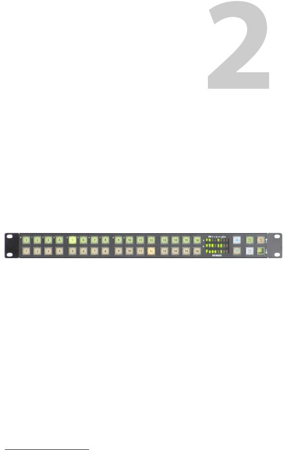
The NV96051 is a 1RU panel, 1.75” deep, overall. It has 2 sets of backlit function buttons and a small display. The display has 3 distinct LED readouts each having 8 characters.
The NV9605 can operate in one of 2 modes. See Modes of Operation, following.
The panel is organized as shown in figures 2-1 and 2-2:
|
|
|
|
|
|
|
|
|
|
|
|
|
|
|
Function Buttons |
|
Display |
|
|
|
|
|
|
|
Function Buttons |
||||
|
|
|
|
|
||||||||||
|
|
Scroll Buttons |
|
|
|
|
|
|
|
|
||||
|
|
|
|
|
|
|
|
|
|
|||||
Fig. 2-1: NV9605 Front
The function buttons select sources or destinations, or perform some task such as locking a destination. The function buttons are configurable. More functions are available for the rightmost 4 buttons than for the buttons on the left of the display.
The scroll buttons (‘Page Up’ and ‘Page Down’) are not configurable buttons. Using the scroll buttons, the operator can scroll through 4 “pages” of sources and destinations.
After selecting any one of the pages, the operator can further select one of two sets of sources using a configured ‘Source Shift’ button. Thus, every source button potentially represents 8 sources, depending on the page in use and the state of the ‘Source Shift’ button.
There is no corresponding ‘Destination Shift’ function. There is only one set of destinations for each page.
The scroll buttons are also used when the panel is in menu mode (to change the illumination of the buttons). See Menu Mode on page 39.
1. An equivalent NV9605V — a GUI that is called a “virtual panel”— is available. It emulates the NV9605.
3
Introduction
Panel Organization
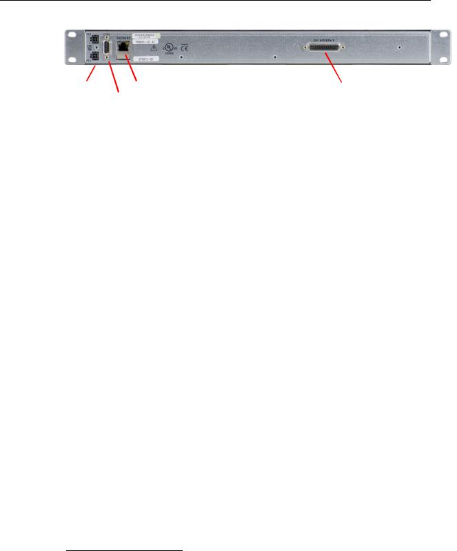
At the rear of the panel are power, serial control, Ethernet, and GPIO connectors:
Power |
|
|
|
|
|
|
|
Ethernet (RJ-45) |
|
|
|
GPIO (DB25) |
|
|
|
|
|
|
|
|
|
||||
|
|
|
|
|
|
|
Serial (RS-422) |
|
|
|||
Fig. 2-2: NV9605 Rear |
|
|
||||||||||
|
|
|
|
|
|
|||||||
You connect the NV9605 to the NV9000 system using the Ethernet connector.
The serial port is for local diagnostics, as it is for all control panels.
The NV9605 uses external PS0001 power supplies. One will suffice. Two provide redundancy.
The GPIO connector supports the panel’s GPIO functions: 4 outputs and 8 inputs. See GPIO on page 45.
Panel Organization
Function Buttons
The NV9605 has an array of 32 function buttons on the left. Four of the 6 buttons on the right are function buttons. (The other 2 buttons on the right are scroll buttons.) The buttons’ functions are only slightly different in each of the 2 operating modes. (See Modes of Operation, next.)
The 10 buttons at the top left are labeled with numerals (0–9). These are for menu operations such as entering the panel ID.
Each button has three operational levels: high and low tally (green or amber), and off. Operators can adjust the low tally levels in increments of 10% using the panel’s menu. Buttons that are turned off are said to be “dark.” (Physically, they are actually white or gray.)
Generally, green represents a source or a source function and amber represents a destination or a destination function.
The function buttons each have clear plastic keycaps under which you may place plastic inserts for button legends. It is a simple matter to change button legends.2
Differences between the Left and Right Function Buttons
All 32 buttons to the left of the display scroll whenever you press a scroll button. The buttons on the pages are independent. For instance, a button that is a source on one page need not necessarily be a source button on another page.
The 4 function buttons on the right behave differently when you scroll:
•Source buttons remain source buttons on all pages, although they can represent different sources on different pages. Destination buttons are destination buttons on all pages, although they can represent different destinations on different pages.
•Other functions (such as ‘Hold’ or ‘Menu’) are fixed and remain the same for all pages.
2.The NV9605V (virtual panel) has automatically generated button legends. For instance, a source button might have 2 lines of text: its “unshifted” source and its “shifted” source, selected with a ‘Source Shift’ button.
4

NV9605
User’s Guide
Alphanumeric Display
The display has 3 display fields.
Display Fields
The display has 3 fields of 8 characters:
•Status, labeled “S” on the panel.
The ‘Status’ field always shows the source that was routed to the currently selected destination, which is identified in the ‘Destination’ field.
•Destination, labeled “D” on the panel.
The ‘Destination’ field shows the current destination.
In multi-destination mode, the destination field shows the most recently selected destination and the status field changes to reflect the source most recently routed to that destination.
•Page, unlabeled.
The ‘Page’ field shows the current page (of four).
The ‘Status’ and ‘Destination’ fields can show either names belonging to a name set or system names depending on (1) the state of the ‘Name Set Toggle’ button (if the panel has one), (2) the default name set (3) the existence of name sets in the NV9000 configuration.
Flags
When a destination is in breakaway, the ‘Source’ field indicates the breakaway with an asterisk in its eighth character position.
The asterisk will obscure the last character of the source name if the name has 8 characters.
Modes of Operation
The NV9605 operates in one of 2 modes:
•Limited X-Y Mode.
•Multi-Destination Mode.
The panel’s set of button functions varies slightly with the mode.
The modes (or behavioral models) are determined at configuration. The operator cannot switch between different modes.
5

Introduction
Other NV9605 Functions
Limited X-Y Mode
In limited X-Y mode, takes occur from a single selectable source to a single selectable destination.
If the panel has any level buttons, operators may perform breakaway—routing sources on fewer than all levels.
Pressing a source button completes the take. There is no ‘Take’ button.
Operators can scroll among 4 pages of sources and destinations and use a ‘Source Shift’ button to toggle between two sets of sources in each page.
Multi-Destination Mode
In this mode, source buttons are configured with destinations as well as sources. Thus, each source button completes a route to an individual destination. If each button had a different destination, it would be possible to route to 32 destinations in each of the 4 pages. The typical configuration would have fewer destinations. The panel uses spacing to separate the left-hand buttons into 4 groups. The most natural number of destinations would be 4 (per page), but that is not a requirement.
There is no ‘Take’ button.
Takes are all-level.
Operators can scroll among 4 pages of sources and destinations and use a ‘Source Shift’ button to toggle between two sets of sources on each page.
Secondary Modes
Additional but secondary modes of panel operation are:
•Setup mode—where the NV9605 is freshly powered up, but disconnected from the network. In this mode, you can preset the NV9605’s panel ID and perform a few diagnostic tasks.
•Menu mode—pressing a menu button places the NV9605 in “menu” mode. In menu mode, the buttons lose their normal functions and become part of a menu that changes as needed during menu operation.
When the panel is not in setup mode or menu mode, we say it is in normal mode. “Normal” means the panel is functioning in one of the 2 operating modes.
Other NV9605 Functions
The NV9605 can be configured to perform the following additional functions:
•Previous source and free source.
•System salvos.
•Lock/protect/release for destinations.
•Multiple-level breakaways.
•Broadcast data routing.
6

Installation
Chapter 3 provides installation and connection instructions.
Topics
Package Contents . . . . . . . . . . . . . . . . . . . . . . . . . . . . . . . . . . . . . . . . . . . . . . . . . . . . . . . . . . . . . . . . . . . . . . . . . 7
Installation . . . . . . . . . . . . . . . . . . . . . . . . . . . . . . . . . . . . . . . . . . . . . . . . . . . . . . . . . . . . . . . . . . . . . . . . . . . . . . . . 7
Installing Software and Documentation . . . . . . . . . . . . . . . . . . . . . . . . . . . . . . . . . . . . . . . . . . . . . . . . . . . 8
Initialization . . . . . . . . . . . . . . . . . . . . . . . . . . . . . . . . . . . . . . . . . . . . . . . . . . . . . . . . . . . . . . . . . . . . . . . . . . . . . . . 8
Testing . . . . . . . . . . . . . . . . . . . . . . . . . . . . . . . . . . . . . . . . . . . . . . . . . . . . . . . . . . . . . . . . . . . . . . . . . . . . . . . . . . . . 9
Package Contents
If you have ordered one or more NV9605 control panels from Miranda, inspect the shipping container for damage. If you find any container damage, unpack and inspect the contents. If the contents are damaged, notify the carrier immediately.
As you unpack the shipping container, look for the packing slip and compare it against the contents to verify that you received everything as ordered. If anything is missing (or if you find equipment damage unrelated to shipping), please contact technical support. Refer to Grass Valley Technical Support on page 63.
Depending on your order, the NV9605 items that can ship include:
•One or more NV9605 control panels.
•One or more power supplies (PS0001) with power cord retention straps.
The package does not contain network cables, serial cables, or mounting screws.
You do not need to take any special precautions regarding ESD.
This document does not address the shipment or installation of any other equipment or software that can be used in conjunction with the NV9605 (including any system controllers, other NV96xx control panels, EC9700 GUI, EC9710 GUI, and configuration programs such as UniConfig, MRC, or NV9000-SE Utilities).
This document does briefly address the use of NV9000-SE Utilities and the Panel IP Configuration Utility as they pertain to panel configuration.
Installation
Follow these steps to install a NV9605 control panel:
1Mount, and secure, the panel in the rack.
The NV9605 is designed to mount in a 19” rack. Rack-mounting is not a requirement.
2We assume that you have an Ethernet switch connected to the “Panel and Router Network” port of your system controller. Connect an Ethernet cable from that switch to the RJ-45 port at the rear of the NV9605.
7
Installation
Installing Software and Documentation
You can also connect the panel using a serial protocol and a serial cable connected at the panel’s DE9 port. The connection is RS-422. The system controller will require a serial port. (The NV960 has several serial card options and breakout boxes for such a connection.) Refer to the NV9000-SE Utilities User’s Guide for serial configuration options. Contact Miranda regarding serial interface options.
3Connect power. It is advisable to connect the power supply to the panel before connecting the power supply to AC current. You can use two power supplies for redundancy.
Installing Software and Documentation
This document is available through the Miranda web site.
You must use NV9000-SE Utilities to configure the NV9605 control panel. Contact Miranda if you need to obtain the latest version of this NV9000 configuration software.
You may use the Panel IP Configuration Utility if you want to your NV9605 to have a static IP address (with respect to the system controller) or to use DHCP. The panel, as it comes from the factory, defaults to DHCP.
Initialization
Before your system controller can communicate with an NV9605, you must give it a panel ID.
Follow these steps for each NV9605 you are installing:
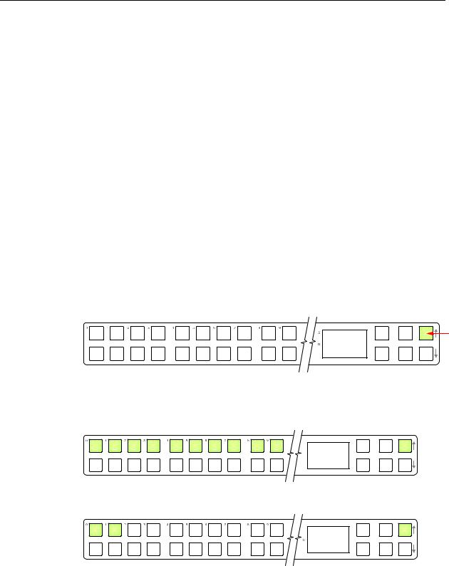
1Power up the NV9605. Do not connect its Ethernet cable. (Disconnect it if it is connected.)
After about a minute, the display will show ‘ACQ IP’ at the top and show the panel’s current panel ID. The top right button is high-tally green:
A C Q I P |
Setup but- |
|
0 |
We call that the “setup” button while the panel is disconnected from the network.
2Press the setup button. The panel now allows you to enter the panel ID using buttons at the left that function as a numeric keypad. The numbers of the keypad a printed on the panel. They range from 0 (at the left) to 9:
 P a n e l I D
 _ _ _ _ _ 1 2 3
Enter the panel ID using the keypad. Then press the setup button again.
3 The panel displays a confirmation message:
 0 C a n c e l
1 |
S a v e |
Press the left-most button to cancel your entry; press the button to the right of it to save your entry.
8

NV9605
User’s Guide
4Press the setup button once again and continue to press the setup button until the panel displays ‘ACQ IP’ once again as in step 1.
5After you enter the panel ID, reconnect the Ethernet cable. The system controller will detect your panel in a few seconds. (All panel IDs must be unique.)
You can now prepare an NV9605 configuration in NV9000-SE Utilities and upload the configuration to the NV9605. You need the panel ID to create a NV9605 configuration. When you upload the configuration, the panel ID you entered in NV9000-SE Utilities designates the actual panel to which the upload will occur. If no actual panel has that ID, the upload cannot occur.
Testing
A panel test function is available when the NV9605 is disconnected from the system controller. Run the test to determine the health of your NV9605. See Setup Mode on page 41 for detail. You can also view the software version numbers under setup mode.
These are points to consider after you install your NV9605 control panel(s):
1Do the buttons illuminate? When an NV9605 powers up, one or more of its buttons are supposed to turn green or amber. Did it pass the panel test mentioned above?
2When the NV9605 powers up and it is connected to the system controller, it should initialize completely. (That takes a few seconds.) The NV9000 system should load whatever configuration exists for that panel and the buttons appropriate for its configuration should light.
If you continue to see “No Server,” “ACQ IP,” or “Locating Network,” you have a problem. Reboot everything and try again.
The NV9605, by default, acquires its IP address through DHCP on the system controller’s panel/router network. You can use the Panel IP Configuration Utility to force the panel to have a static IP address.
If (in setup mode) you do not see your designated panel ID in the ‘Preset’ display field, you have either not initialized the panel or no configuration has been created for your panel in NV9000-SE Utilities.
3Is the system controller actually running? With the typical noise levels in a facility, it can sometimes be difficult to tell. Use the ‘System’ pages of NV9000-SE Utilities to make the determination.
4Is NV9000-SE Utilities installed and operating? If so, can you upload a configuration to the specified panel?
5Does the configuration actually work? Is it useful? Can the operator perform takes and perform other operations?
9

Installation
Testing
10
Configuration
Chapter 4 provides configuration instructions for the NV9605.
Topics
Summary . . . . . . . . . . . . . . . . . . . . . . . . . . . . . . . . . . . . . . . . . . . . . . . . . . . . . . . . . . . . . . . . . . . . . . . . . . . . . . . . 11 Adding a Panel to an NV9000 Configuration . . . . . . . . . . . . . . . . . . . . . . . . . . . . . . . . . . . . . . . . . . . . . . 11 NV9605 Panel Configuration Page . . . . . . . . . . . . . . . . . . . . . . . . . . . . . . . . . . . . . . . . . . . . . . . . . . . . . . . . 14 Pages . . . . . . . . . . . . . . . . . . . . . . . . . . . . . . . . . . . . . . . . . . . . . . . . . . . . . . . . . . . . . . . . . . . . . . . . . . . . . . . . . . . . 15 Commitment Buttons . . . . . . . . . . . . . . . . . . . . . . . . . . . . . . . . . . . . . . . . . . . . . . . . . . . . . . . . . . . . . . . . . . . . 15 Panel Options . . . . . . . . . . . . . . . . . . . . . . . . . . . . . . . . . . . . . . . . . . . . . . . . . . . . . . . . . . . . . . . . . . . . . . . . . . . . 16 Button Definitions . . . . . . . . . . . . . . . . . . . . . . . . . . . . . . . . . . . . . . . . . . . . . . . . . . . . . . . . . . . . . . . . . . . . . . . . 18 Multi-Destination Configuration . . . . . . . . . . . . . . . . . . . . . . . . . . . . . . . . . . . . . . . . . . . . . . . . . . . . . . . . . . 23 Single-Destination Configuration . . . . . . . . . . . . . . . . . . . . . . . . . . . . . . . . . . . . . . . . . . . . . . . . . . . . . . . . . 24
This chapter addresses configurers. Operators and other persons not interested in NV9605 configuration need not read this chapter.
Summary
The NV9605 is a relatively simple panel. It has 36 function buttons, 2 scroll buttons, and a small display. It has 2 operating modes.
•Limited X-Y Mode.
•Multi-Destination Mode.
The set of button functions varies slightly between modes.
NV9000-SE Utilities is the software with which to configure the NV9605. Figure 4-1, following, shows the default NV9605 panel configuration page from NV9000-SE Utilities.
Adding a Panel to an NV9000 Configuration
You must create configurations for the NV9605 using NV9000-SE Utilities. We assume that you are familiar enough with NV9000-SE Utilities that you can understand the following material. It is not difficult material, but some of the concepts might not be familiar to everyone.
It takes only a few seconds to add a new panel configuration.
11
Configuration
Adding a Panel to an NV9000 Configuration
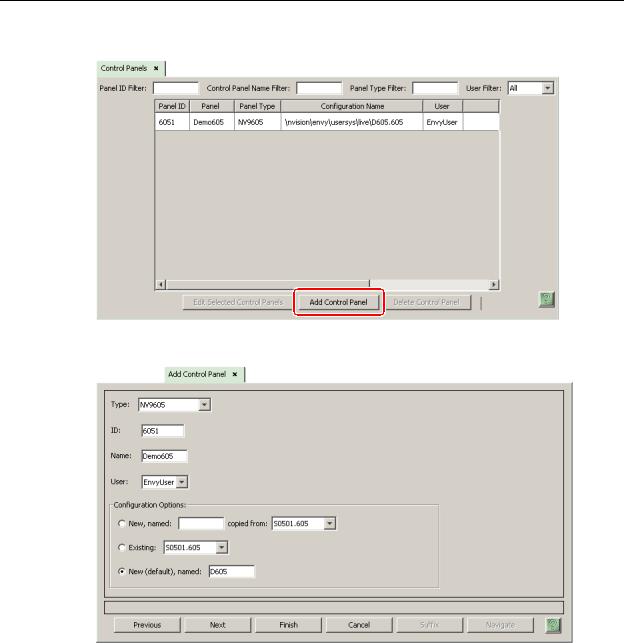
After launching NV9000-SE Utilities, choose ‘Control Panels’ from the Configuration pane in the navigation area. The ‘Control Panels’ configuration page appears:
Click ‘Add Control Panel’ at the bottom of the configuration page. The ‘Add Control Panel’ page appears:
Choose “NV9605” from the ‘Type’ field. In the ID field, enter the panel ID you assigned to the panel while it was in setup mode. (You can change the panel ID in NV9000-SE Utilities.) Give a name to the panel in the name field and select a user.
When you are creating a panel configuration you have 3 options. These options are presented in the ‘Configuration Options’ area:
1 Make a copy of an existing configuration file, giving it a new file name.
2 Use an existing configuration file. (This allows several panels to share a single configuration.)
3 Create an entirely new configuration file.
12
NV9605
User’s Guide
In the first and third cases, you will create a new configuration file whose name you designate. The file extension for an NV9605 configuration file is .605. Click ‘Next’ or ‘Finish’ to proceed. Click ‘Previous’ to go back the previous page. Click ‘Cancel’ to terminate the entry operation.
There are 2 other buttons, ‘Suffix’ and ‘Navigate’, both dim (disabled). These do not apply to the NV9605.
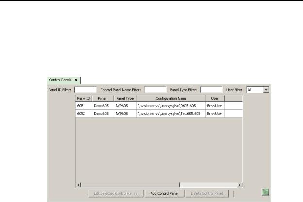
Return to the ‘Control Panels’ page to view your new entry. To edit an NV9605 configuration, double-click its list entry:
You will then see the panel configuration page for the selected NV9605.
Following is a discussion of how to use the panel configuration page in which you configure an NV9605.
13
Loading...