


 Loading...
Compact Router
System Configurator
User’s Guide
Miranda Technologies Inc.
3499 Douglas B. Floreani
Montreal, Quebec
Canada H4S 2C6

CR Series—CRSC User’s Guide
•Revision: 2.0
•Software Version: 1.6.0
•Part Number: UG0032-03
•Copyright: © 2010 Miranda Technologies. All rights reserved.
•No part of this manual may be reproduced in any form by photocopy, microfilm, xerography or any other means, or incorporated into any information retrieval system, electronic or mechanical, without the written permission of Miranda Technologies, Inc.
•The information contained in this manual is subject to change without notice or obligation.
•All title and copyrights as well as trade secret, patent and other proprietary rights in and to the Software Product (including but not limited to any images, photographs, animations, video, audio, music, test, and “applets” incorporated into the Software Product), the accompanying printed materials, and any copies of the Software Product, are owned by Miranda Technologies, Inc. The Software Product is protected by copyright laws and international treaty provisions. Customer shall not copy the printed materials accompanying the software product.
Notice
The software contains proprietary information of Miranda Technologies, Inc. It is provided under a license agreement containing restrictions on use and disclosure and is also protected by copyright law. Reverse engineering of the software is prohibited.
Due to continued product development, the accuracy of the information in this document may change without notice. The information and intellectual property contained herein is confidential between Miranda and the client and remains the exclusive property of Miranda. If you find any problems in the documentation, please report them to us in writing. Miranda does not warrant that this document is error-free.
FCC Statement
This equipment has been tested and found to comply with the limits for a Class A digital device, pursuant to part 15 of the FCC Rules. These limits are designed to provide reasonable protection against harmful interference when the equipment is operated in a commercial environment. This equipment generates, uses, and can radiate radio frequency energy and, if not installed and used in accordance with the instruction manual, may cause harmful interference to radio communications. Operation of this equipment in a residential area is likely to cause harmful interference in which case the user will be required to correct the interference at his own expense.
Declaration of Conformance (CE)
All of the equipment described in this manual has been designed to conform with the required safety and emissions standards of the European Community. Products tested and verified to meet these standards are marked as required by law with the CE mark. (See Symbols and Their Meanings on page v.)
ii |
|
Rev 2.0 • 29 Mar 10 |
|
When shipped into member countries of the European Community, this equipment is accompanied by authentic copies of original Declarations of Conformance on file in Miranda GVD offices in Grass Valley, California USA.
Trademarks
Miranda is a registered trademark of Miranda Technologies, Inc.
Brand and product names mentioned in this manual may be trademarks, registered trademarks or copyrights of their respective holders. All brand and product names mentioned in this manual serve as comments or examples and are not to be understood as advertising for the products or their manufactures.
Software License Agreement and Warranty Information
Contact Miranda for details on the software license agreement and product warranty.
Technical Support Contact Information
Miranda has made every effort to ensure that the equipment you receive is in perfect working order and that the equipment fits your needs. In the event that problems arise that you cannot resolve, or if there are any questions regarding this equipment or information about other products manufactured by Miranda, please contact your local representative or contact Miranda directly through one of the appropriate means listed here.
•Main telephone: 530-265-1000 (9 am to 9 pm PST) Fax: 530-265-1021
In the Americas, call toll-free: +1-800-224-7882 (9 am to 9 pm EST)
In Europe, the Middle East, African or the UK, call +44 (0) 1491 820222 (9 am to 6 pm, GMT) In France, call +33 1 55 86 87 88 (9 am to 5 pm, GMT + 1)
In Asia, call +852-2539-6987 (9 am to 5 pm, GMT + 8) In China, call +86-10-5873-1814
•Emergency after hours: toll-free: +1-800-224-7882 Tel: +1-514-333-1772
•E-Mail:
In the Americas, support@miranda.com
In Europe, the Middle East, African or the UK, eurotech@miranda.com In France, eurotech@miranda.com
In Asia, asiatech@miranda.com In China, asiatech@miranda.com
•Website: http://www.miranda.com
|
Shipping |
|
Miranda GVD |
Miranda GVD |
|
P.O. Box 1658 |
125 Crown Point Court |
|
Nevada City, CA 95959, USA |
Grass Valley, CA 95945, USA |
|
|
|
|
Note |
Return Material Authorization (RMA) required for all returns. |
|
|
|
|
Compact Router System Configurator • User’s Guide |
|
iii |
|

Change History
The table below lists the changes to the Compact Router User’s Guide.
•User’s Guide Part # UG0032-03
•Software version: 1.6.0
Rev |
Date |
ECO |
Description |
Approved By |
|
|
|
|
|
|
|
1.0 |
17 |
Nov 08 |
14426 |
Initial Release |
D. Cox |
|
|
|
|
|
|
1.1 |
31 Mar 09 |
15703 |
New format |
D.Cox |
|
|
|
|
|
|
|
1.2 |
12 |
Oct 09 |
16114 |
Restructured online help. New software features |
DEM |
|
|
|
|
|
|
2.0 |
29 Mar 10 |
16912 |
Addition of CQX routers |
DEM, SM, TS |
|
|
|
|
|
|
|
iv |
|
Rev 2.0 • 29 Mar 10 |
|

Important Safeguards and Notices
This section provides important safety guidelines for operators and service personnel. Specific warnings and cautions appear throughout the manual where they apply. Please read and follow this important information, especially those instructions related to the risk of electric shock or injury to
persons. |
|
|
|
Warning |
Any instructions in this manual that require opening the equipment cover or |
|
enclosure are for use by qualified service personnel only. To reduce the risk of |
|
electric shock, do not perform any service other than that contained in the |
|
operating instructions unless you are qualified to do so. |
|
|
Symbols and Their Meanings
The lightning flash with arrowhead symbol within an equilateral triangle alerts the user to the presence of dangerous voltages within the product’s enclosure that may be of sufficient magnitude to constitute a risk of electric shock to persons.
The exclamation point within an equilateral triangle alerts the user to the presence of important operating and maintenance/service instructions.
The Ground symbol represents a protective grounding terminal. Such a terminal must be connected to earth ground prior to making any other connections to the equipment.
The fuse symbol indicates that the fuse referenced in the text must be replaced with one having the ratings indicated.
The presence of this symbol in or on Miranda equipment means that it has been designed, tested and certified as complying with applicable Underwriter’s Laboratory (USA) regulations and recommendations.
The presence of this symbol in or on Miranda equipment means that it has been designed, tested and certified as essentially complying with all applicable European Union (CE) regulations and recommendations.
Compact Router System Configurator • User’s Guide |
|
v |
|
General Warnings
A warning indicates a possible hazard to personnel which may cause injury or death. Observe the following general warnings when using or working on this equipment:
•Heed all warnings on the unit and in the operating instructions.
•Do not use this equipment in or near water.
•This equipment is grounded through the grounding conductor of the power cord. To avoid electrical shock, plug the power cord into a properly wired receptacle before connecting the equipment inputs or outputs.
•Route power cords and other cables so they are not likely to be damaged.
•Disconnect power before cleaning the equipment. Do not use liquid or aerosol cleaners; use only a damp cloth.
•Dangerous voltages may exist at several points in this equipment. To avoid injury, do not touch exposed connections and components while power is on.
•Do not wear rings or wristwatches when troubleshooting high current circuits such as the power supplies.
•To avoid fire hazard, use only the specified fuse(s) with the correct type number, voltage and current ratings as referenced in the appropriate locations in the service instructions or on the equipment. Always refer fuse replacements to qualified service personnel.
•To avoid explosion, do not operate this equipment in an explosive atmosphere.
•Have qualified service personnel perform safety checks after any service.
General Cautions
A caution indicates a possible hazard to equipment that could result in equipment damage. Observe the following cautions when operating or working on this equipment:
•When installing this equipment, do not attach the power cord to building surfaces.
•To prevent damage to equipment when replacing fuses, locate and correct the problem that caused the fuse to blow before re-applying power.
•Use only the specified replacement parts.
•Follow static precautions at all times when handling this equipment.
•This product should only be powered as described in the manual. To prevent equipment damage, select the proper line voltage on the power supply(ies) as described in the installation documentation.
•To prevent damage to the equipment, read the instructions in the equipment manual for proper input voltage range selection.
•Some master control products include a backup battery. There is a risk of explosion if the battery is replaced by a battery of an incorrect type. Dispose of batteries according to instructions.
•Products that have (1) no on/off switch and (2) use an external power supply must be installed in proximity to a main power output that is easily accessible.
vi |
|
Rev 2.0 • 29 Mar 10 |
|

Table of Contents
Chapter 1 |
What Is New . . . . . . . . . . . . . . . . . . . . . . . . . . . . . . . . . . . . . . . . . . . . . . . . . . . . . . . . . . . . . . |
. 1 |
|
Changes . . . . . . . . . . . . . . . . . . . . . . . . . . . . . . . . . . . . . . . . . . . . . . . . . . . . . . . . . . . . . . . . . . . . . |
. 1 |
|
CQX (“Clean and Quiet”) Products . . . . . . . . . . . . . . . . . . . . . . . . . . . . . . . . . . . . . . . . . . . . |
. 1 |
|
New IP Addresses . . . . . . . . . . . . . . . . . . . . . . . . . . . . . . . . . . . . . . . . . . . . . . . . . . . . . . . . . |
. 1 |
|
Persistent IP Addresses and Levels . . . . . . . . . . . . . . . . . . . . . . . . . . . . . . . . . . . . . . . . . . . . |
. 2 |
|
Single Control Panel and Multiple Routers . . . . . . . . . . . . . . . . . . . . . . . . . . . . . . . . . . . . . . |
. 2 |
|
Configurable Remote Panels . . . . . . . . . . . . . . . . . . . . . . . . . . . . . . . . . . . . . . . . . . . . . . . . . |
. 2 |
|
Salvos . . . . . . . . . . . . . . . . . . . . . . . . . . . . . . . . . . . . . . . . . . . . . . . . . . . . . . . . . . . . . . . . . . . |
. 2 |
|
Sources and Destinations No Longer Tied to I/O Position . . . . . . . . . . . . . . . . . . . . . . . . . . |
. 2 |
|
Lock Management and Crosspoint View. . . . . . . . . . . . . . . . . . . . . . . . . . . . . . . . . . . . . . . . |
. 3 |
|
Easy Firmware Updates . . . . . . . . . . . . . . . . . . . . . . . . . . . . . . . . . . . . . . . . . . . . . . . . . . . . . |
. 3 |
|
New Compact Routers Supported . . . . . . . . . . . . . . . . . . . . . . . . . . . . . . . . . . . . . . . . . . . . . |
. 3 |
Chapter 2 |
Before Using CRSC. . . . . . . . . . . . . . . . . . . . . . . . . . . . . . . . . . . . . . . . . . . . . . . . . . . . . . . . |
. 5 |
|
About CRSC . . . . . . . . . . . . . . . . . . . . . . . . . . . . . . . . . . . . . . . . . . . . . . . . . . . . . . . . . . . . . . . . . |
. 5 |
|
Upload Recent Firmware . . . . . . . . . . . . . . . . . . . . . . . . . . . . . . . . . . . . . . . . . . . . . . . . . . . . . . . . |
. 6 |
|
Panel Locked at Reset . . . . . . . . . . . . . . . . . . . . . . . . . . . . . . . . . . . . . . . . . . . . . . . . . . . . . . . . . . |
. 7 |
|
System Design . . . . . . . . . . . . . . . . . . . . . . . . . . . . . . . . . . . . . . . . . . . . . . . . . . . . . . . . . . . . . . . . |
. 7 |
|
Design Issues . . . . . . . . . . . . . . . . . . . . . . . . . . . . . . . . . . . . . . . . . . . . . . . . . . . . . . . . . . . . . |
. 7 |
|
Creating a Network . . . . . . . . . . . . . . . . . . . . . . . . . . . . . . . . . . . . . . . . . . . . . . . . . . . . . . . . . . . . |
. 8 |
|
What is a Subnet?. . . . . . . . . . . . . . . . . . . . . . . . . . . . . . . . . . . . . . . . . . . . . . . . . . . . . . . . . . |
. 9 |
|
What is a Subnet Mask?. . . . . . . . . . . . . . . . . . . . . . . . . . . . . . . . . . . . . . . . . . . . . . . . . . . . . |
. 9 |
|
What is an IP Address? . . . . . . . . . . . . . . . . . . . . . . . . . . . . . . . . . . . . . . . . . . . . . . . . . . . . . |
. 9 |
|
Rotary Switches . . . . . . . . . . . . . . . . . . . . . . . . . . . . . . . . . . . . . . . . . . . . . . . . . . . . . . . |
10 |
|
Initial Assembly . . . . . . . . . . . . . . . . . . . . . . . . . . . . . . . . . . . . . . . . . . . . . . . . . . . . . . . |
10 |
|
Powering Up Re-initializes . . . . . . . . . . . . . . . . . . . . . . . . . . . . . . . . . . . . . . . . . . . . . . |
10 |
|
Network Speeds . . . . . . . . . . . . . . . . . . . . . . . . . . . . . . . . . . . . . . . . . . . . . . . . . . . . . . . . . . . |
11 |
|
Cabling . . . . . . . . . . . . . . . . . . . . . . . . . . . . . . . . . . . . . . . . . . . . . . . . . . . . . . . . . . . . . . . . . . |
11 |
|
CQX Networks. . . . . . . . . . . . . . . . . . . . . . . . . . . . . . . . . . . . . . . . . . . . . . . . . . . . . . . . . . . . |
11 |
|
Mode Rotary Switch . . . . . . . . . . . . . . . . . . . . . . . . . . . . . . . . . . . . . . . . . . . . . . . . . . . |
11 |
|
Frame ID Rotary Switch . . . . . . . . . . . . . . . . . . . . . . . . . . . . . . . . . . . . . . . . . . . . . . . . |
12 |
|
Setting Up the Configuration PC and Installing CRSC . . . . . . . . . . . . . . . . . . . . . . . . . . . . . . . . . |
12 |
|
How to Configure your PC’s IP Address. . . . . . . . . . . . . . . . . . . . . . . . . . . . . . . . . . . . . . . . |
13 |
|
How to Create Multiple Subnets . . . . . . . . . . . . . . . . . . . . . . . . . . . . . . . . . . . . . . . . . . |
15 |
|
How to Install CRSC . . . . . . . . . . . . . . . . . . . . . . . . . . . . . . . . . . . . . . . . . . . . . . . . . . . . . . . |
16 |
|
Installation Testing. . . . . . . . . . . . . . . . . . . . . . . . . . . . . . . . . . . . . . . . . . . . . . . . . . . . . . . . . . . . . |
16 |
Chapter 3 |
Show Products Online . . . . . . . . . . . . . . . . . . . . . . . . . . . . . . . . . . . . . . . . . . . . . . . . . . . . |
17 |
Chapter 4 |
CR Series Ethernet Setttings. . . . . . . . . . . . . . . . . . . . . . . . . . . . . . . . . . . . . . . . . . . . . . . |
19 |
|
CQX Routers — Separate Subnet. . . . . . . . . . . . . . . . . . . . . . . . . . . . . . . . . . . . . . . . . . . . . . |
19 |
|
An Overview of Networking . . . . . . . . . . . . . . . . . . . . . . . . . . . . . . . . . . . . . . . . . . . . . . . . . . . . . |
19 |
|
Using the ‘CR Series Ethernet Settings’ Page . . . . . . . . . . . . . . . . . . . . . . . . . . . . . . . . . . . . |
20 |
|
How to Add Routers to a Network. . . . . . . . . . . . . . . . . . . . . . . . . . . . . . . . . . . . . . . . . . . . . |
20 |
|
How to Add Remote Panels to a Network . . . . . . . . . . . . . . . . . . . . . . . . . . . . . . . . . . . . . . . |
21 |
|
How to Change Ethernet Settings . . . . . . . . . . . . . . . . . . . . . . . . . . . . . . . . . . . . . . . . . . . . . |
22 |
Compact Router System Configurator • User’s Guide |
|
vii |
|
Table of Contents
Chapter 5 |
Configuring Router Levels . . . . . . . . . . . . . . . . . . . . . . . . . . . . . . . . . . . . . . . . . . . . . . . . |
25 |
|
Overview . . . . . . . . . . . . . . . . . . . . . . . . . . . . . . . . . . . . . . . . . . . . . . . . . . . . . . . . . . . . . . . . . . . . |
25 |
|
Levels and Partitions . . . . . . . . . . . . . . . . . . . . . . . . . . . . . . . . . . . . . . . . . . . . . . . . . . . . . . . |
25 |
|
Using the ‘Configure Router Levels’ Page . . . . . . . . . . . . . . . . . . . . . . . . . . . . . . . . . . . . . . |
26 |
|
Active Subnet. . . . . . . . . . . . . . . . . . . . . . . . . . . . . . . . . . . . . . . . . . . . . . . . . . . . . . . . . |
27 |
|
Signal Types. . . . . . . . . . . . . . . . . . . . . . . . . . . . . . . . . . . . . . . . . . . . . . . . . . . . . . . . . . |
28 |
|
How to Create or Update a Level. . . . . . . . . . . . . . . . . . . . . . . . . . . . . . . . . . . . . . . . . . . . . . |
28 |
|
How to Create Multiple Levels . . . . . . . . . . . . . . . . . . . . . . . . . . . . . . . . . . . . . . . . . . . . . . . |
29 |
|
How to Delete a Level . . . . . . . . . . . . . . . . . . . . . . . . . . . . . . . . . . . . . . . . . . . . . . . . . . . . . . |
29 |
Chapter 6 |
Setting Up Machine Control Routers . . . . . . . . . . . . . . . . . . . . . . . . . . . . . . . . . . . . . . |
31 |
|
An Overview of Machine Control Routers . . . . . . . . . . . . . . . . . . . . . . . . . . . . . . . . . . . . . . . . . . |
31 |
|
Viewing Machine Control Router Crosspoints . . . . . . . . . . . . . . . . . . . . . . . . . . . . . . . . . . . |
32 |
|
Machine Control Router Port Types . . . . . . . . . . . . . . . . . . . . . . . . . . . . . . . . . . . . . . . . . . . |
32 |
|
Using the ‘Setup Machine Control Router’ Page. . . . . . . . . . . . . . . . . . . . . . . . . . . . . . . . . . |
34 |
|
How to Select a Machine Control Router . . . . . . . . . . . . . . . . . . . . . . . . . . . . . . . . . . . . . . . |
35 |
|
How to Change a Port Type. . . . . . . . . . . . . . . . . . . . . . . . . . . . . . . . . . . . . . . . . . . . . . . . . . |
36 |
Chapter 7 |
Programming Remote Panels . . . . . . . . . . . . . . . . . . . . . . . . . . . . . . . . . . . . . . . . . . . . . |
37 |
|
Overview . . . . . . . . . . . . . . . . . . . . . . . . . . . . . . . . . . . . . . . . . . . . . . . . . . . . . . . . . . . . . . . . . . . . |
37 |
|
Configuring Remote Panels . . . . . . . . . . . . . . . . . . . . . . . . . . . . . . . . . . . . . . . . . . . . . . . . . . |
37 |
|
“Captive” Panels . . . . . . . . . . . . . . . . . . . . . . . . . . . . . . . . . . . . . . . . . . . . . . . . . . . . . . . . . . |
38 |
|
Standard Mode . . . . . . . . . . . . . . . . . . . . . . . . . . . . . . . . . . . . . . . . . . . . . . . . . . . . . . . . |
38 |
|
Enhanced Mode (Hold and No-hold). . . . . . . . . . . . . . . . . . . . . . . . . . . . . . . . . . . . . . . |
39 |
|
About Salvos . . . . . . . . . . . . . . . . . . . . . . . . . . . . . . . . . . . . . . . . . . . . . . . . . . . . . . . . . . . . . |
39 |
|
Using the ‘Program Remote Panels’ Page . . . . . . . . . . . . . . . . . . . . . . . . . . . . . . . . . . . . . . . |
40 |
|
Button Functions . . . . . . . . . . . . . . . . . . . . . . . . . . . . . . . . . . . . . . . . . . . . . . . . . . . . . . . . . . |
42 |
|
Destination . . . . . . . . . . . . . . . . . . . . . . . . . . . . . . . . . . . . . . . . . . . . . . . . . . . . . . . . . . . |
42 |
|
Levels . . . . . . . . . . . . . . . . . . . . . . . . . . . . . . . . . . . . . . . . . . . . . . . . . . . . . . . . . . . . . . . |
43 |
|
Salvos . . . . . . . . . . . . . . . . . . . . . . . . . . . . . . . . . . . . . . . . . . . . . . . . . . . . . . . . . . . . . . . |
43 |
|
Sources . . . . . . . . . . . . . . . . . . . . . . . . . . . . . . . . . . . . . . . . . . . . . . . . . . . . . . . . . . . . . . |
44 |
|
Unused . . . . . . . . . . . . . . . . . . . . . . . . . . . . . . . . . . . . . . . . . . . . . . . . . . . . . . . . . . . . . . |
45 |
|
How to View an Existing Panel Configuration . . . . . . . . . . . . . . . . . . . . . . . . . . . . . . . . . . . |
45 |
|
How to Create a New Panel Configuration . . . . . . . . . . . . . . . . . . . . . . . . . . . . . . . . . . . . . . |
45 |
|
How to Change a Button Function. . . . . . . . . . . . . . . . . . . . . . . . . . . . . . . . . . . . . . . . . . . . . |
46 |
|
How to Change a Button Label . . . . . . . . . . . . . . . . . . . . . . . . . . . . . . . . . . . . . . . . . . . . . . . |
47 |
|
How to Change the Panel Operation Mode . . . . . . . . . . . . . . . . . . . . . . . . . . . . . . . . . . . . . . |
48 |
Chapter 8 |
Viewing Router Crosspoints. . . . . . . . . . . . . . . . . . . . . . . . . . . . . . . . . . . . . . . . . . . . . . . |
49 |
|
Discussion . . . . . . . . . . . . . . . . . . . . . . . . . . . . . . . . . . . . . . . . . . . . . . . . . . . . . . . . . . . . . . . . . . . |
49 |
|
About AES Crosspoints . . . . . . . . . . . . . . . . . . . . . . . . . . . . . . . . . . . . . . . . . . . . . . . . . . . . . |
49 |
|
Using the ‘View Router Crosspoints’ Page . . . . . . . . . . . . . . . . . . . . . . . . . . . . . . . . . . . . . . |
50 |
|
How to View an Existing Panel Crosspoint Configuration . . . . . . . . . . . . . . . . . . . . . . . . . . |
51 |
|
How to Perform or Undo a Take . . . . . . . . . . . . . . . . . . . . . . . . . . . . . . . . . . . . . . . . . . . . . . |
51 |
Chapter 9 |
Firmware Updates . . . . . . . . . . . . . . . . . . . . . . . . . . . . . . . . . . . . . . . . . . . . . . . . . . . . . . . . |
53 |
|
Discussion . . . . . . . . . . . . . . . . . . . . . . . . . . . . . . . . . . . . . . . . . . . . . . . . . . . . . . . . . . . . . . . . . . . |
53 |
|
Using the ‘Firmware Updates’ Page . . . . . . . . . . . . . . . . . . . . . . . . . . . . . . . . . . . . . . . . . . . |
53 |
|
How to Update Firmware. . . . . . . . . . . . . . . . . . . . . . . . . . . . . . . . . . . . . . . . . . . . . . . . . . . . |
54 |
|
How to View Past Update Reports . . . . . . . . . . . . . . . . . . . . . . . . . . . . . . . . . . . . . . . . . . . . |
55 |
|
How to Reset Frames . . . . . . . . . . . . . . . . . . . . . . . . . . . . . . . . . . . . . . . . . . . . . . . . . . . . . . . |
56 |
viii |
|
Rev 1.1 • 29 Mar 10 |
|
Table of Contents
Chapter 10 |
Lock Maintenance . . . . . . . . . . . . . . . . . . . . . . . . . . . . . . . . . . . . . . . . . . . . . . . . . . . . . . . . |
57 |
|
Discussion . . . . . . . . . . . . . . . . . . . . . . . . . . . . . . . . . . . . . . . . . . . . . . . . . . . . . . . . . . . . . . . . . . . |
57 |
|
Using the ‘Lock Maintenance’ Page . . . . . . . . . . . . . . . . . . . . . . . . . . . . . . . . . . . . . . . . . . . |
57 |
|
How to Unlock an Individual or All Locks . . . . . . . . . . . . . . . . . . . . . . . . . . . . . . . . . . . . . . |
58 |
Chapter 11 |
Setup NV9000 Remote Panel. . . . . . . . . . . . . . . . . . . . . . . . . . . . . . . . . . . . . . . . . . . . . . |
59 |
|
Discussion . . . . . . . . . . . . . . . . . . . . . . . . . . . . . . . . . . . . . . . . . . . . . . . . . . . . . . . . . . . . . . . . . . . |
59 |
|
Using the ‘Setup NV9000 Remote Panel’ Page. . . . . . . . . . . . . . . . . . . . . . . . . . . . . . . . . . . |
59 |
|
How to Setup an NV9000 Remote Panel. . . . . . . . . . . . . . . . . . . . . . . . . . . . . . . . . . . . . . . . |
61 |
|
How to Disable NV9000 Control. . . . . . . . . . . . . . . . . . . . . . . . . . . . . . . . . . . . . . . . . . . . . . |
61 |
Chapter 12 |
Tutorials . . . . . . . . . . . . . . . . . . . . . . . . . . . . . . . . . . . . . . . . . . . . . . . . . . . . . . . . . . . . . . . . . |
63 |
|
Routing Overview . . . . . . . . . . . . . . . . . . . . . . . . . . . . . . . . . . . . . . . . . . . . . . . . . . . . . . . . . . . . . |
63 |
|
What is a Router?. . . . . . . . . . . . . . . . . . . . . . . . . . . . . . . . . . . . . . . . . . . . . . . . . . . . . . . . . . |
63 |
|
Inside the Router . . . . . . . . . . . . . . . . . . . . . . . . . . . . . . . . . . . . . . . . . . . . . . . . . . . . . . |
64 |
|
Sources and Destinations . . . . . . . . . . . . . . . . . . . . . . . . . . . . . . . . . . . . . . . . . . . . . . . . |
65 |
|
What is a Control Panel? . . . . . . . . . . . . . . . . . . . . . . . . . . . . . . . . . . . . . . . . . . . . . . . . . . . . |
65 |
|
Signals . . . . . . . . . . . . . . . . . . . . . . . . . . . . . . . . . . . . . . . . . . . . . . . . . . . . . . . . . . . . . . . . . . |
65 |
|
A Note About AES Signal Types . . . . . . . . . . . . . . . . . . . . . . . . . . . . . . . . . . . . . . . . . |
66 |
|
A Note About Machine Control Signals . . . . . . . . . . . . . . . . . . . . . . . . . . . . . . . . . . . . |
66 |
|
Partitions and Levels . . . . . . . . . . . . . . . . . . . . . . . . . . . . . . . . . . . . . . . . . . . . . . . . . . . . . . . |
67 |
|
Router Control . . . . . . . . . . . . . . . . . . . . . . . . . . . . . . . . . . . . . . . . . . . . . . . . . . . . . . . . . . . . |
67 |
|
Remote Panel Operating Modes. . . . . . . . . . . . . . . . . . . . . . . . . . . . . . . . . . . . . . . . . . . . . . . . . . . |
68 |
|
Standard Mode . . . . . . . . . . . . . . . . . . . . . . . . . . . . . . . . . . . . . . . . . . . . . . . . . . . . . . . . . . . . |
68 |
|
Enhanced Mode . . . . . . . . . . . . . . . . . . . . . . . . . . . . . . . . . . . . . . . . . . . . . . . . . . . . . . . . . . . |
68 |
|
Salvos . . . . . . . . . . . . . . . . . . . . . . . . . . . . . . . . . . . . . . . . . . . . . . . . . . . . . . . . . . . . . . . . . . . . . . . |
69 |
|
Cabling . . . . . . . . . . . . . . . . . . . . . . . . . . . . . . . . . . . . . . . . . . . . . . . . . . . . . . . . . . . . . . . . . . . . . . |
69 |
|
Cable Types . . . . . . . . . . . . . . . . . . . . . . . . . . . . . . . . . . . . . . . . . . . . . . . . . . . . . . . . . . . . . . |
70 |
|
Connectors . . . . . . . . . . . . . . . . . . . . . . . . . . . . . . . . . . . . . . . . . . . . . . . . . . . . . . . . . . . . . . . |
70 |
|
Serial Connector. . . . . . . . . . . . . . . . . . . . . . . . . . . . . . . . . . . . . . . . . . . . . . . . . . . . . . . |
70 |
|
DB25 Connectors. . . . . . . . . . . . . . . . . . . . . . . . . . . . . . . . . . . . . . . . . . . . . . . . . . . . . . |
71 |
|
RJ-45 Connectors. . . . . . . . . . . . . . . . . . . . . . . . . . . . . . . . . . . . . . . . . . . . . . . . . . . . . . |
71 |
|
Making Connections . . . . . . . . . . . . . . . . . . . . . . . . . . . . . . . . . . . . . . . . . . . . . . . . . . . . . . . |
71 |
|
Sample Configuration . . . . . . . . . . . . . . . . . . . . . . . . . . . . . . . . . . . . . . . . . . . . . . . . . . . . . . |
72 |
|
Equipment . . . . . . . . . . . . . . . . . . . . . . . . . . . . . . . . . . . . . . . . . . . . . . . . . . . . . . . . . . . |
72 |
|
Analysis . . . . . . . . . . . . . . . . . . . . . . . . . . . . . . . . . . . . . . . . . . . . . . . . . . . . . . . . . . . . . |
72 |
|
Partitioning. . . . . . . . . . . . . . . . . . . . . . . . . . . . . . . . . . . . . . . . . . . . . . . . . . . . . . . . . . . |
73 |
|
Operational Considerations . . . . . . . . . . . . . . . . . . . . . . . . . . . . . . . . . . . . . . . . . . . . . . |
75 |
|
Cabling Diagram . . . . . . . . . . . . . . . . . . . . . . . . . . . . . . . . . . . . . . . . . . . . . . . . . . . . . . |
75 |
|
Products . . . . . . . . . . . . . . . . . . . . . . . . . . . . . . . . . . . . . . . . . . . . . . . . . . . . . . . . . . . . . . . . . . . . . |
77 |
|
Summary . . . . . . . . . . . . . . . . . . . . . . . . . . . . . . . . . . . . . . . . . . . . . . . . . . . . . . . . . . . . . . . . |
77 |
|
Routers . . . . . . . . . . . . . . . . . . . . . . . . . . . . . . . . . . . . . . . . . . . . . . . . . . . . . . . . . . . . . . . . . . |
78 |
|
Control Panels . . . . . . . . . . . . . . . . . . . . . . . . . . . . . . . . . . . . . . . . . . . . . . . . . . . . . . . . . . . . |
79 |
|
Remote Panel Modules . . . . . . . . . . . . . . . . . . . . . . . . . . . . . . . . . . . . . . . . . . . . . . . . . . . . . |
79 |
|
Usage . . . . . . . . . . . . . . . . . . . . . . . . . . . . . . . . . . . . . . . . . . . . . . . . . . . . . . . . . . . . . . . . . . . |
79 |
|
Software . . . . . . . . . . . . . . . . . . . . . . . . . . . . . . . . . . . . . . . . . . . . . . . . . . . . . . . . . . . . . . . . . |
81 |
|
Benefits . . . . . . . . . . . . . . . . . . . . . . . . . . . . . . . . . . . . . . . . . . . . . . . . . . . . . . . . . . . . . . . . . |
81 |
|
The Routers . . . . . . . . . . . . . . . . . . . . . . . . . . . . . . . . . . . . . . . . . . . . . . . . . . . . . . . . . . . . . . |
81 |
|
Digital Video Routers . . . . . . . . . . . . . . . . . . . . . . . . . . . . . . . . . . . . . . . . . . . . . . . . . . |
83 |
|
3Gig Video Routers . . . . . . . . . . . . . . . . . . . . . . . . . . . . . . . . . . . . . . . . . . . . . . . . . . . |
84 |
|
HD Video Routers . . . . . . . . . . . . . . . . . . . . . . . . . . . . . . . . . . . . . . . . . . . . . . . . . . . . . |
84 |
|
SD Video Routers . . . . . . . . . . . . . . . . . . . . . . . . . . . . . . . . . . . . . . . . . . . . . . . . . . . . . |
84 |
|
NR Video Routers . . . . . . . . . . . . . . . . . . . . . . . . . . . . . . . . . . . . . . . . . . . . . . . . . . . . . |
84 |
|
CQX Video Routers . . . . . . . . . . . . . . . . . . . . . . . . . . . . . . . . . . . . . . . . . . . . . . . . . . . |
84 |
|
Analog Video Routers . . . . . . . . . . . . . . . . . . . . . . . . . . . . . . . . . . . . . . . . . . . . . . . . . . |
86 |
Compact Router System Configurator • User’s Guide |
|
ix |
|
Table of Contents
Digital Audio Routers . . . . . . . . . . . . . . . . . . . . . . . . . . . . . . . . . . . . . . . . . . . . . . . . . . 86 Analog Audio Routers . . . . . . . . . . . . . . . . . . . . . . . . . . . . . . . . . . . . . . . . . . . . . . . . . 88 Machine Control Routers . . . . . . . . . . . . . . . . . . . . . . . . . . . . . . . . . . . . . . . . . . . . . . . 88 Background Information . . . . . . . . . . . . . . . . . . . . . . . . . . . . . . . . . . . . . . . . . . . . . . . . 89 Controlling or Controlled. . . . . . . . . . . . . . . . . . . . . . . . . . . . . . . . . . . . . . . . . . . . . . . . 89 Dynamic . . . . . . . . . . . . . . . . . . . . . . . . . . . . . . . . . . . . . . . . . . . . . . . . . . . . . . . . . . . . . 89 Master or Slave . . . . . . . . . . . . . . . . . . . . . . . . . . . . . . . . . . . . . . . . . . . . . . . . . . . . . . . 89 Configuration . . . . . . . . . . . . . . . . . . . . . . . . . . . . . . . . . . . . . . . . . . . . . . . . . . . . . . . . . 90
The Control Panels. . . . . . . . . . . . . . . . . . . . . . . . . . . . . . . . . . . . . . . . . . . . . . . . . . . . . . . . . 90 1RU Panels. . . . . . . . . . . . . . . . . . . . . . . . . . . . . . . . . . . . . . . . . . . . . . . . . . . . . . . . . . . 90 CQX Panel . . . . . . . . . . . . . . . . . . . . . . . . . . . . . . . . . . . . . . . . . . . . . . . . . . . . . . . . . . . 90 2RU Panels. . . . . . . . . . . . . . . . . . . . . . . . . . . . . . . . . . . . . . . . . . . . . . . . . . . . . . . . . . . 91 The Remote Panel Modules . . . . . . . . . . . . . . . . . . . . . . . . . . . . . . . . . . . . . . . . . . . . . . . . . . 92
Chapter 13 |
Operating Panels . . . . . . . . . . . . . . . . . . . . . . . . . . . . . . . . . . . . . . . . . . . . . . . . . . . . . . . . |
. 93 |
|
Control Panel Buttons . . . . . . . . . . . . . . . . . . . . . . . . . . . . . . . . . . . . . . . . . . . . . . . . . . . . . . . . . |
. 93 |
|
Button Types . . . . . . . . . . . . . . . . . . . . . . . . . . . . . . . . . . . . . . . . . . . . . . . . . . . . . . . . . |
94 |
|
Panel Modes. . . . . . . . . . . . . . . . . . . . . . . . . . . . . . . . . . . . . . . . . . . . . . . . . . . . . . . . . . |
94 |
|
Red Buttons . . . . . . . . . . . . . . . . . . . . . . . . . . . . . . . . . . . . . . . . . . . . . . . . . . . . . . . . . . |
95 |
|
Button Order . . . . . . . . . . . . . . . . . . . . . . . . . . . . . . . . . . . . . . . . . . . . . . . . . . . . . . . . . . . . . |
95 |
|
Spatial Ordering . . . . . . . . . . . . . . . . . . . . . . . . . . . . . . . . . . . . . . . . . . . . . . . . . . . . . . |
95 |
|
Temporal Ordering . . . . . . . . . . . . . . . . . . . . . . . . . . . . . . . . . . . . . . . . . . . . . . . . . . . . |
95 |
|
Button Illumination . . . . . . . . . . . . . . . . . . . . . . . . . . . . . . . . . . . . . . . . . . . . . . . . . . . . . . . . |
95 |
|
Source Button Lighting . . . . . . . . . . . . . . . . . . . . . . . . . . . . . . . . . . . . . . . . . . . . . . . . . |
96 |
|
Destination Button Lighting. . . . . . . . . . . . . . . . . . . . . . . . . . . . . . . . . . . . . . . . . . . . . . |
96 |
|
Level Button Lighting . . . . . . . . . . . . . . . . . . . . . . . . . . . . . . . . . . . . . . . . . . . . . . . . . . |
96 |
|
CQX Panel Buttons . . . . . . . . . . . . . . . . . . . . . . . . . . . . . . . . . . . . . . . . . . . . . . . . . . . . . . . . |
97 |
|
Power Up and Reset. . . . . . . . . . . . . . . . . . . . . . . . . . . . . . . . . . . . . . . . . . . . . . . . . . . . . . . . . . . . |
98 |
|
During System Construction . . . . . . . . . . . . . . . . . . . . . . . . . . . . . . . . . . . . . . . . . . . . . . . . . |
98 |
|
Routers at Power-Up . . . . . . . . . . . . . . . . . . . . . . . . . . . . . . . . . . . . . . . . . . . . . . . . . . . . . . . |
98 |
|
Remote Panel Modules at Power-Up . . . . . . . . . . . . . . . . . . . . . . . . . . . . . . . . . . . . . . . . . . . |
98 |
|
Performing Takes. . . . . . . . . . . . . . . . . . . . . . . . . . . . . . . . . . . . . . . . . . . . . . . . . . . . . . . . . . . . . . |
99 |
|
Normal Takes. . . . . . . . . . . . . . . . . . . . . . . . . . . . . . . . . . . . . . . . . . . . . . . . . . . . . . . . . . . . . |
99 |
|
Example — Normal Take in Standard Mode . . . . . . . . . . . . . . . . . . . . . . . . . . . . . . . . . |
99 |
|
Example — Normal Take in Enhanced Mode . . . . . . . . . . . . . . . . . . . . . . . . . . . . . . . |
100 |
|
Breakaway Takes . . . . . . . . . . . . . . . . . . . . . . . . . . . . . . . . . . . . . . . . . . . . . . . . . . . . . . . . . |
100 |
|
Example — Breakaway in Standard Mode. . . . . . . . . . . . . . . . . . . . . . . . . . . . . . . . . . |
100 |
|
Example — Breakaway in Enhanced Mode without Hold — Variant 1. . . . . . . . . . . . |
101 |
|
Example — Breakaway in Enhanced Mode without Hold — Variant 2. . . . . . . . . . . . |
102 |
|
Example — Breakaway in Enhanced Mode with Hold . . . . . . . . . . . . . . . . . . . . . . . . |
103 |
|
CP3201 Takes . . . . . . . . . . . . . . . . . . . . . . . . . . . . . . . . . . . . . . . . . . . . . . . . . . . . . . . . . . . |
104 |
|
Example — Normal Take for CP3201 . . . . . . . . . . . . . . . . . . . . . . . . . . . . . . . . . . . . . |
104 |
|
Example — Breakaway for CP3201 in Standard Mode . . . . . . . . . . . . . . . . . . . . . . . . |
104 |
|
Example — Breakaway for CP3201 in Enhanced Mode with Hold . . . . . . . . . . . . . . |
105 |
|
Example — Breakaway Take for CP3201 in Enhanced Mode without Hold . . . . . . . |
105 |
|
Machine Control Takes . . . . . . . . . . . . . . . . . . . . . . . . . . . . . . . . . . . . . . . . . . . . . . . . . . . . |
106 |
|
CQX Takes. . . . . . . . . . . . . . . . . . . . . . . . . . . . . . . . . . . . . . . . . . . . . . . . . . . . . . . . . . . . . . |
107 |
|
Performing Locks. . . . . . . . . . . . . . . . . . . . . . . . . . . . . . . . . . . . . . . . . . . . . . . . . . . . . . . . . . . . . |
107 |
|
Panel Lock . . . . . . . . . . . . . . . . . . . . . . . . . . . . . . . . . . . . . . . . . . . . . . . . . . . . . . . . . . . . . . |
107 |
|
Destination Locks . . . . . . . . . . . . . . . . . . . . . . . . . . . . . . . . . . . . . . . . . . . . . . . . . . . . . . . . |
107 |
|
Simple Locks . . . . . . . . . . . . . . . . . . . . . . . . . . . . . . . . . . . . . . . . . . . . . . . . . . . . . . . . |
108 |
|
Complex Locks . . . . . . . . . . . . . . . . . . . . . . . . . . . . . . . . . . . . . . . . . . . . . . . . . . . . . . |
108 |
|
CP3201 Locks and Unlocks. . . . . . . . . . . . . . . . . . . . . . . . . . . . . . . . . . . . . . . . . . . . . |
108 |
|
Executing Salvos . . . . . . . . . . . . . . . . . . . . . . . . . . . . . . . . . . . . . . . . . . . . . . . . . . . . . . . . . . . . . |
109 |
x |
|
Rev 1.1 • 29 Mar 10 |
|
Table of Contents
|
Performing Level Selection . . . . . . . . . . . . . . . . . . . . . . . . . . . . . . . . . . . . . . . . . . . . . . . . . . . . |
. 109 |
|
Level Selection in Standard Mode . . . . . . . . . . . . . . . . . . . . . . . . . . . . . . . . . . . . . . . . . . . |
. 110 |
|
Button Order . . . . . . . . . . . . . . . . . . . . . . . . . . . . . . . . . . . . . . . . . . . . . . . . . . . . . . . . |
110 |
|
Level Selection in Enhanced Mode . . . . . . . . . . . . . . . . . . . . . . . . . . . . . . . . . . . . . . . . . . . |
112 |
Chapter 14 |
Glossary. . . . . . . . . . . . . . . . . . . . . . . . . . . . . . . . . . . . . . . . . . . . . . . . . . . . . . . . . . . . . . . . . |
113 |
Index |
. . . . . . . . . . . . . . . . . . . . . . . . . . . . . . . . . . . . . . . . . . . . . . . . . . . . . . . . . . . . . . . . . . . . . . . . . |
115 |
Compact Router System Configurator • User’s Guide |
|
xi |
|
Table of Contents
xii |
|
Rev 1.1 • 29 Mar 10 |
|

1. What Is New
Before using the Compact Router System Configurator (CRSC), please review the following list of feature enhancements and system changes.
Changes
CQX (“Clean and Quiet”) Products
CRSC supports the new CQX (“clean and quiet”) router and CQX control panel. The CQX router and CQX panel are designed to work together as a single unit and are not usable as a separate router or panel at this time.
A CQX router performs smooth transitions in both HD and SD video and audio. The CQX control panel has 4 dedicated transition type buttons (cut, v-fade, cut-fade, and fade-cut). Transitions may be slow (3 seconds), medium (2 seconds) or fast (1 second). The number of frames used for a transition depends on the video frame rate, as follows:
•1080i59.94, NTSC — slow 90, medium 60, fast 30.
•1080i50, PAL — slow 75, medium 50, fast 25.
•720p50 — slow 150, medium 100, fast 50.
•720p60 — slow 180, medium 120, fast 60.
A CQX router operates only with a CQX control panel. The CQX panel can be local (mounted on a CQX router) or it can be remote (mounted on a remote panel module). The remote CQX panel must be connected to the CQX router by an Ethernet switch. However, the transition rate or transition type buttons of a CQX control panel mounted on a remote panel module do not operate.
All CQX routers and control panels must exist on a separate subnet from other CR Series products. For more information, see CR Series Ethernet Setttings on page 19.
New IP Addresses
The default IP address for routers and remote control panels have been changed. Previously, the default IP addresses were:
Routers — 192.168.x where x= the switch setting plus 20.
Remote Panel Modules — 192.168.x where x = the switch setting plus 24. The current default IP addresses are now:
Routers — 192.168.x where x = the switch setting plus 100.
Remote Panel Modules — 192.168.x where x = the switch setting plus 50.
(xxx.yyy.zzz denotes the subnet determined by the router or remote panel module. The default is 192.168.2.).
For instructions on managing IP addresses, see Chapter 4.
Compact Router System Configurator • User’s Guide |
|
1 |
|
1. What Is New
Changes
Persistent IP Addresses and Levels
After routers and remote panels are configured for your network, IP addresses and levels are no longer associated with rotary switches. IP addresses can be whatever suits your purposes. The CRSC software can detect and manage multiple independent router networks (subnets) if your configuration PC has the appropriate network connections.
You can define up to 4 partitions (i.e., levels) for any router, subject to a limit of 8 levels in any subnet. CRSC does not support more than 4 routers in a subnet. Gateways are supported for third-party system developers. See CR Series Ethernet Setttings on page 19.
Single Control Panel and Multiple Routers
When a control panel is mounted on a router, and several routers are connected to that router network, the control panel can control all connected routers. If CRSC is used to make any configuration changes on the router to which the control panel is attached, the control panel will only control the router it is attached to. To resolve this issue, attach the control panel to a remote panel module. Once attached to a remote panel module, the control panel is once again able to control all attached routers.
If the routers are no longer in default mode, the control panel must be configured. “0” reset will return the router to default mode.
Note |
Setting the rotary switch on the control panel to “0” (reset) will return the router |
|
to default mode. |
|
|
Configurable Remote Panels
Any button — except the lock buttons — on a remote panel can be programmed as a source button, destination button, salvo button, or level selection button.
Captive panels — those mounted on routers — cannot be configured. They act in default defaultmode and control only the router on which they are mounted.
Remote panels can be configured in any of 3 different modes:
•Standard Mode on page 68.
•Enhanced Mode, with hold, on page 68.
•Enhanced Mode, without hold, on page 68.
Salvos
A salvo is a set of pre-defined low-level takes. Salvos can rapidly perform many repeatable tasks. To learn about salvos, see Salvos on page 69. For instructions on adding salvos and salvo buttons, see About Salvos on page 39.
Sources and Destinations No Longer Tied to I/O Position
Sources and destinations are no longer tied to the position of input and output connections on the routers. Control panel “real estate” is more effectively utilized. Sources and destinations are defined in the course of panel configuration. (See chapter 7 on page 37.)
2 |
|
Rev 2.0 • 29 Mar 10 |
|
1. What Is New
Changes
Lock Management and Crosspoint View
After your CRSC network is running, you can use CRSC software for maintenance and diagnostics of your network. The ‘Lock Management’ page enables you to view and clear any or all locks. (See chapter 10 on page 57.) The ‘View Router Crosspoints’ page lets you perform takes from your PC and view, in real time, the takes that operators make on the their control panels. (See chapter 8 on page 49.)
Easy Firmware Updates
Update all devices in your network at once with just a few clicks. (See chapter 9 on page 53.)
New Compact Routers Supported
CRSC now supports Miranda’s line of non-reclocked compact routers and 8×8 compact routers.
Compact Router System Configurator • User’s Guide |
|
3 |
|
1. What Is New
Changes
4 |
|
Rev 2.0 • 29 Mar 10 |
|

2. Before Using CRSC
Before Compact Router System Configurator (CRSC) can be used effectively, the following tasks must first be completed:
1If you are new to CRSC, review About CRSC on page 5.
2Upload new firmware using CRSC. See Upload Recent Firmware on page 6.
3Be sure that any reset panels are unlocked. See Panel Locked at Reset on page 7.
4If you have not already done it, create a system design. See System Design on page 7.
5Create a network and add compact routers or remote panels to the network. (A remote panel is a control panel mounted on a remote panel module.) See Creating a Network on page 8.
6Set up the configuration PC and install CRSC. See Setting Up the Configuration PC and Installing CRSC on page 12.
7Test the CRSC installation to ensure that everything is working properly. See Installation Testing on page 16.
Once these tasks are complete, you are ready to start using CRSC. If you are unfamiliar with routing, networking concepts, or Compact Router Series products, it is strongly recommended that you review the Tutorials on page 63. It provides overviews on several relevant topics, such as routing, signal types and levels. For detailed information on using a specific compact router or control panel, refer to that product’s documentation.
About CRSC
CRSC (Compact Router System Configurator) is configuration software that runs on your PC. A compact router network developed using CRSC offers many benefits:
CRSC might require that your older routers and remote panel modules be updated with firmware compatible with CRSC. This should present no problem to you other than the few minutes it takes.
You can use CRSC to initialize your remote panel module(s) for use with a NV9000 network and to restore those remote panel module(s) to use under CRSC.
Using CRSC, the following benefits can be realized:
•Configurable panels
A stand-alone system is not configurable.
In a CRSC system, you can create and configure router levels, and exercise control over network device addresses. You can also save and restore panel configuration files. CRSC supports 3 panel operating modes.
•Partitioning
A stand-alone system does not allow router partitioning.
A CRSC network allows partitioning. A “level” is equivalent to a partition.
Compact Router System Configurator • User’s Guide |
|
5 |
|

2. Before Using CRSC
Upload Recent Firmware
•Configurable networks
A stand-alone network comprises up to 4 routers and up to 16 remote panels. IP addresses depend on the devices’ rotary switches and router levels are limited to the range 1–4.
A CRSC network supports up to 4 routers, up to 8 levels, and up to 16 remote panels. IP addresses are configurable.
You can create many Compact Router networks. If you do, CRSC can manage them all at once as long as your configuration PC has the network connections to do so. CRSC treats multiple CRSC networks as “subnets.”
•Efficient multi-level ‘takes’ and breakaway
In a stand-alone system, panel buttons have a fixed and limited association with router inputs and outputs.
In a CRSC network, remote panel buttons have a configurable association with router inputs and outputs. In fact, remote panels control “sources” and destinations,” not merely inputs and outputs. Consequently, CRSC systems can use less equipment and do so more effectively.
Remote panels configured in “enhanced” mode provide automatic level selection. Remote panels in a CRSC system provide breakaway status.
•CRSC systems can perform salvos.
•CRSC can perform system monitoring. You can examine and set crosspoints and view and clear locks on your PC.
•CRSC simplifies firmware updates with a single file for all Compact Router Series devices. All Compact Router Series devices can (and should) be updated at the same time.
In addition to the benefits of using CRSC, configuration changes can be made easily and quickly. CRSC has 4 primary configuration functions:
•Organize devices on your Ethernet LAN.
•Define levels and router partitions.
•Specify machine control port settings.
•Configure control panels.
There are also 3 secondary (maintenance and monitoring) functions:
•View router crosspoints.
•Upload firmware to the routers and remote panel modules.
•Examine, set, or clear destination locks.
Upload Recent Firmware
We strongly recommend that when you receive CRSC that you upload the most recent firmware to all your compact routers and remote panel modules before proceeding. This is done after the frames have been added to the CRSC network. For instructions, see How to Update Firmware on page 54.
6 |
|
Rev 2.0 • 29 Mar 10 |
|

2. Before Using CRSC
Panel Locked at Reset
Panel Locked at Reset
At reset, a panel is locked. The panel lock button (at the top right) is red. Before using a panel, you must unlock the panel by pressing the red ‘Panel Lock’ button.
System Design
By the time you are ready to install your equipment and software most of the system design decisions have likely already been made. However, it may be helpful to review the following sections to ensure all issues have been captured in your system design.
Because design issues require an understanding of routing, if you are unfamiliar with routing concepts, see What is a Router? on page 63.
Design Issues
What signals do you intend to manage? How many are there?
What are the signal types? Will you need machine control routers?
Are you using CQX (“clean and quiet”) routers? If so, CQX routers only operate by themselves with CQX control panels and must be on a separate subnet from other routers.
A compact router has a maximum of 16 or 32 inputs or outputs. (An AES router in mono mode has a 64×64 matrix although it is still considered a 32×32 router.) How you partition a router depends in part on the organization of buttons on your control panels and similarly the organization of buttons depends in part on router partitions.
Router partitions are contiguous sets of connectors. For example, you cannot alternate SD and HD signals on odd and even connectors. You cannot keep multiple AES connectors (e.g., AES 1/2, 3/4, 5/6, and 7/8) clustered together; they must be separated.
Router partitions, especially for AES or machine control routers, depend on many factors:
AES partitions – Number of AES channels. Number of embedded audio channels. Machine control partitions – What kind of devices you have that require machine control.
HD routers can switch SD signals. You do not need a separate SD router unless you have more than 32 HD devices. If you have a 3Gig router, it can switch HD and SD signals as well as 3Gig signals.
You can switch analog signals using Analog Video (AV) and Analog Audio (AA) routers. You can also use analog-to-digital (A/D) and digital-to-analog (D/A) converters in conjunction with HD, SD, and AES routers when you have analog signals. Whether this is an effective solution depends on factors that include your budget, whether you need or already have A/D and D/A converters, and how much delay you can tolerate in your video or audio.
Whether your video signals contain embedded audio is another issue: Do you actually need any audio routers?
Compact Router Series routers and panels do not start, stop, rewind, cue, or otherwise control any media. You will need to purchase equipment that performs those tasks. You must consider how that equipment works in conjunction with Compact Router Series products.
Compact Router System Configurator • User’s Guide |
|
7 |
|

2. Before Using CRSC
Creating a Network
For additional assistance, review the Sample Configuration on page 72. It illustrates design issues that you might encounter.
Creating a Network
Compact Router Series (CR Series) products and CRSC communicate through a network. There are three main reasons to create a network:
•To perform multi-level operations, such as ‘takes’ and locks.
•To operate routers or a network of routers remotely (e.g., from a separate room).
•To make use of CRSC features, such as configuring remote panels. Remember that it is actually the remote panel module that is configurable.
A CRSC network can be comprised of:
•From 1 to 16 remote panel modules (with attached control panels).
You can add at most 16 remote panel modules at any one time. Once added—with network addresses assigned in CRSC—the frames remain identifiable and configurable and more frames can be added.
•From 1 to 4 compact routers. You can mix CR Series routers of any size and type according to your requirements.
You can add at most 4 routers at any one time. If the routers you are adding are already set to use different subnets, the limit of 4 does not hold. However, routers from the factory are usually set to the same subnet: 192.168.2. Routers that are freshly initialized also use that subnet.
The network must also include:
•One or more PCs (running Windows XP or Vista) on which you have installed CRSC or other configuration software.
•An Ethernet switch (or hub) capable of 100 MB/s operation with enough ports to accommodate your routers, remote panels, and PCs.
If you are using only CR Series routers, the typical network uses a single Ethernet switch, a single subnet, and a variety of routers, panels, and configuration PCs connected at the switch. If you are also using any CQX routers and control panels, a second, separate subnet must be created for the CQX products. The control panels and routers communicate by sending messages across the network. The different devices on the network are identifiable by their unique numbers (IP addresses).
If any routers or control panels on the network have identical IP addresses, the devices are not distinguishable and the network may not functions properly. CRSC notifies you of any identical IP addresses and which frames are inaccessible on a specific subnet.
8 |
|
Rev 2.0 • 29 Mar 10 |
|
2. Before Using CRSC
Creating a Network
Figure 2-1 shows a sample network of routers with remote panel modules.
Figure 2-1. Sample Network
You can create multiple CRSC networks. CRSC can detect and manage all networks as long as two conditions are met:
•Each network is defined as a distinct subnet.
•Your configuration PC has enough network connections to support the different subnets.
What is a Subnet?
A subnet is an identifiably separate part of an organization's network that allows a single large network to be broken down into smaller ones. Typically, a subnet may represent all the machines at one geographic location or on the same local area network (LAN). All CR Series routers and control panels must be on a separate subnet from any CQX routers and control panels. However, devices must be on the same subnet to communicate with each other. For example, a router can only receive commands from a control panel on the same subnet.
What is a Subnet Mask?
A subnet mask is the technique used by the IP protocol to create a subnet address. Or, to put it another way, a subnet mask is a screen of numbers used for routing traffic within a subnetwork. In CRSC, the subnet mask is typically: 255.255.255.0. The subnet masks need not be 255.255.255.0, but if it differs, the frame address range will be something other than 1–254.
What is an IP Address?
An IP address is a 32-bit number given by four 8-bit values (octets) separated by periods: 192.168.2.87 (for example). The number is comprised of a subnet and a frame address. Each network must be a distinct subnet in CRSC and CR Series routers and CR Series panels must be on a separate subnet from CQX routers and CQX control panels.
Using that subnet, a router’s or remote panel’s frame address is the last octet in the address. For example, if the router’s full IP address is 192.168.2.87, the router’s frame address is 87 and the subnet is 192.168.2. A frame address can range from 1 to 254. The values 0 and 255 are not allowed because they have special meaning.
Compact Router System Configurator • User’s Guide |
|
9 |
|
2. Before Using CRSC
Creating a Network
Rotary Switches
The 16-position rotary switch located on the front of a router or remote panel module is used to determine a device’s initial IP address. Routers and remote panel modules usually come from the factory with the switch set to 1. Once the frames are added to your network, you can use CRSC to assign a different IP addresses, if you want. After that, the rotary switches are generally irrelevant.
The switches have hexadecimal position numbers from 0 to 9 and A to F. In hex notation, each letter represents the following:
A = 10, B = 11, C = 12, D = 13, E = 14, F = 15
The switch is then added to a present number to create the initial IP address for the router or panel. If a rotary switch is set to zero (0), the router or panel reverts to the factory default state, not to a previously set state.
In the following, the subnet is represented by xxx.yyy.zzz:
For CR Series routers, IP address = xxx.yyy.zzz.sss where sss = switch value + 100.
For CQX routers, IP address = xxx.yyy.zzz.sss where sss = switch value + 200. Use only a switch setting in the range 1–4 (addresses 201 to 204).
For remote panel modules, IP address = xxx.yyy.zzz.sss where sss = switch value + 50.
Using these formulas, a router and a control panel can have the same switch setting because each is being added to a unique number. However, two routers or two control panels cannot have the same switch setting because the resulting number would be the same creating identical IP addresses.
Remember that each device must have a unique IP address. If the devices are on the same subnet, use the rotary switch setting plus the value listed above to create the default, IP address making sure that the frame number is unique.
Remember that CQX routers and control panels must be on a separate subnet.
For instructions on setting switch settings, see How to Add Routers to a Network on page 20 and How to Add Remote Panels to a Network on page 21. After you add the router or remote panel to the network, you can change its IP address using CRSC. See How to Change Ethernet Settings on page 22.
Initial Assembly
During the initial physical assembly of routers, panels, and remote panel modules, you need to ensure that:
•All routers and remote panel modules have their rotary switches set to unique settings before adding them to the network
•The switch settings of the routers and remote panel modules are non-zero and distinct.
Powering Up Re-initializes
A router or remote panel module re-initializes to its factory default settings if you power it up with the rotary switch set to zero (0). If you reset the frame by accident, and the frame is in your network, you will have to add the frame again and reconfigure it.
10 |
|
Rev 2.0 • 29 Mar 10 |
|

2. Before Using CRSC
Creating a Network
Network Speeds
Compact router networks are Ethernet LANs (100 Mb/s, UDP). That means they are reasonably fast, and have potentially many network configuration options. However, no matter how fast the network is, the amount of network traffic increases exponentially with the number of devices on the network. At some point, the traffic exceeds the capacity of the network. The practical limit is 4 compact routers and about 16 remote panel modules.
Cabling
In general, router networks and machine control ports use ordinary Ethernet cable and connectors (RJ-45). However, some frames have DE9 connectors. To make network connections to these devices, you will need to acquire DE9-to-RJ45 cables.
Analog audio connectors are DB25. Each connector supports 8 audio channels (4 stereo pairs). You will need to acquire breakout cables to connect individual analog audio devices, such as Miranda’s WC0053 breakout cable.
CQX Networks
A CQX router must be operated with a CQX control panel (or automation). Do not place a CQX router on a subnet with other routers. However, you can have more than one subnet dedicated to CQX routers.
Figure 3-3 shows the ways a “clean and quiet” router can be connected:
Figure 2-2. Figure 3-3. CQX Network
The CQX panel can be local (mounted on a CQX router) or it can be remote (mounted on a remote panel module). The remote CQX panel then must be connected to the CQX router by an Ethernet switch. It is possible to use both a captive panel and a remote panel.
Unlike other compact routers, the CQX routers have two rotary switches. You must set both switches to an appropriate value.
Mode Rotary Switch
The ‘Mode’ rotary switch configures the router’s video format. Set this 16-position rotary switch to a position in the range 0–5 according to this table:
Setting |
Format |
||
|
|
|
|
0 |
1080i, |
59.94 |
|
|
|
|
|
1 |
1080i, |
50 |
|
|
|
|
|
2 |
525i, |
59.94 |
|
|
|
|
|
3 |
625i, |
50 |
|
|
|
|
|
Compact Router System Configurator • User’s Guide |
|
11 |
|

2. Before Using CRSC
Setting Up the Configuration PC and Installing CRSC
Setting |
Format |
|
|
|
|
4 |
720p, |
59.94 |
|
|
|
5 |
720p, |
50 |
|
|
|
The 1080p formats are not yet available. The default is 1080i, 59.94 Hz (switch setting 0).
Note |
Every time you make a switch change, power-cycle the router. |
|
|
Frame ID Rotary Switch
You must set up the IP addresses for the router (and a remote panel, if you have one). First, use the rotary switch on the router (and remote panel module) to set an initial IP address. For a CQX router, the address = switch value + 200. The default IP address is 192.168.2.address. Thus, address ranges from 201 to 215. However, use only a switch setting in the range 1–4 (addresses 201 to 204).
For remote panel modules, address = switch value + 50. The default IP address is 192.168.2.address. Here, address ranges from 51 to 65.
The numbers on the rotary switch are in hexadecimal: 0–F. Do not use 0 because 0 causes the router or remote panel module to be reset. After you perform the setup using the rotary switches, you can use CRSC to change the IP addresses from the defaults.
Note |
Every time you make a switch change, power-cycle the router. |
|
|
Setting Up the Configuration PC and Installing CRSC
After the CRSC network is setup, you are ready to configure the PC that will run CRSC. Once the PC is configured, you can install the CRSC application on that computer.
The PC must be assigned an IP address on one of the subnets you intend to use for the CRSC network. Usually the subnet is 192.168.2 because that is the default subnet assigned to all Compact Router Series products.
If you have multiple subnets in your compact router system, you will probably have to add those subnets to your PC’s network configuration. Doing this is especially important for CQX routers.
12 |
|
Rev 2.0 • 29 Mar 10 |
|
2. Before Using CRSC
Setting Up the Configuration PC and Installing CRSC
How to Configure your PC’s IP Address
1From the PC’s Start menu, choose ‘Settings > Network Connections’ or 'All Programs > Accessories > Communications > Network Connections', whichever is available. The ‘Network Connections’ dialog box appears:
Figure 2-3. Network Connections Window
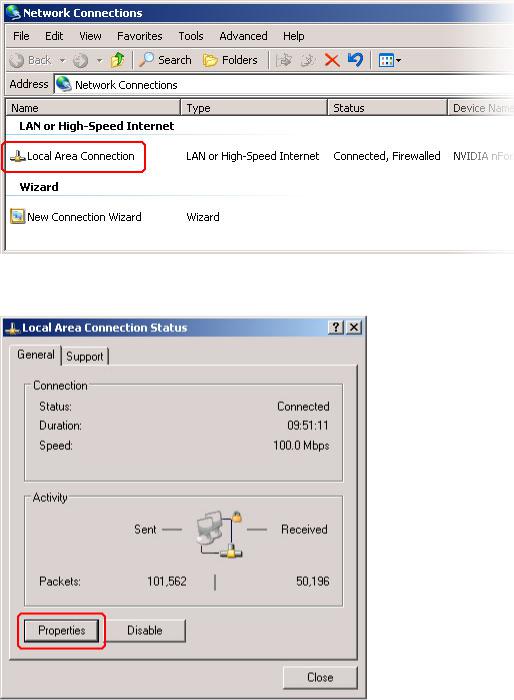
2Double-click ‘Local Area Connection’. The ‘Local Area Connection Status’ dialog box appears:
Figure 2-4. Local Area Connection Status Dialog Box
Compact Router System Configurator • User’s Guide |
|
13 |
|

2. Before Using CRSC
Setting Up the Configuration PC and Installing CRSC
3Choose the ‘General’ tab and click Properties. The ‘Local Area Connection Properties’ dialog box appears.
Figure 2-5. Local Area Connection Properties Dialog Box
14 |
|
Rev 2.0 • 29 Mar 10 |
|

2. Before Using CRSC
Setting Up the Configuration PC and Installing CRSC
4Select ‘Internet Protocol (TCP/IP)’ and click Properties. The ‘Internet Protocol (TCP/IP) Properties’ dialog box appears.
Figure 2-6. Internet Protocol (TCP/IP) Properties Dialog Box
5Select ‘Use the following IP address’ and enter the IP address for your PC. It is recommended that you use the default subnet 192.168.2 and the subnet mask 255.255.255.0.
Any unique IP address will work as long as it is on one of the subnets of your CRSC network. The PC’s address on the subnet must not be the same as any of the frames (routers or remote panels) on the subnet. It is recommended that you use Avoid addresses in the 50, 100 and 200 range. CRSC uses those as defaults. For details, see What is an IP Address? on page 9.
6Click OK to save your changes.
How to Create Multiple Subnets
1Starting from step 4 in the preceding procedure, click Advanced.
2In the ‘Advanced’ window, click Add and enter an IP address for your PC on each of the subnets. Repeat this step for additional subnets.
3After adding IP addresses for your subnets, click OK.
Compact Router System Configurator • User’s Guide |
|
15 |
|

2. Before Using CRSC
Installation Testing
How to Install CRSC
The CR Series (Compact Router) is available on the CD (SB0033-xx) that ships with the equipment. CRSC is a Java application and the installer installs a Java runtime support package. The installer creates a desktop shortcut for CRSC and makes an entry in Windows’ Start menu for CRSC.
To install, place the CD in the CD drive of your PC. The CD should autoplay and present an option to run the CRSC installer. Choose the option and follow the instructions. The software installation process takes about one minute.
Installation Testing
After installing CRSC, launch CRSC by clicking the desktop icon or selecting ‘NVISION > Compact Router System Configurator’ from the ‘Start’ menu. Click the ‘Compact Router Series Ethernet Settings’ link to open the ‘Compact Router Series Ethernet Settings’ page and view list of devices in your network.
Examine the list of devices and note if any of the following exist:
•No entries in the list. Either you have no network or the network is not properly connected to your PC. Ensure that your PC has an Ethernet connection to the Ethernet switch for the network.
•Entries read “IP Conflict.” There might be a duplicate IP address. To fix this issue, adjust the rotary switch setting on your frames. The switch settings for each router must be unique from any other router; the switch settings for each remote panel module must be unique from any other remote panel module. (See Rotary Switches on page 10.)
If you determine that IP addresses are not a problem, one of the frames might be disconnected, have no power, or might be defective. Again, check Ethernet connections, power connections, and power supplies. A power supply light and the power indicators on all routers, remote panel modules, and control panels should be on.
•Entries read “Different Subnet.” These are frames that are detectable by CRSC, but are not on a currently available subnet. To view available subnets, move the mouse pointer and hover over “Different Subnet.” A popup list of available subnets appears.
There are several options for such entries:
Change the IP address of the frame to the current subnet. Change the IP address or subnet of the configuration PC.
Change the IP address in some other way, but leaving the device on some other subnet. Physically remove the frame from the network by disconnecting the connecting cables.
Fix any problems and click Refresh List on the ‘Compact Router Series Ethernet Settings’ page to view an updated list of devices. Once the network is functioning properly, you are ready to use CRSC to perform other tasks.
16 |
|
Rev 2.0 • 29 Mar 10 |
|

3. Show Products Online
The ‘NVISION Series Products Online’ page lists all products — compact routers, remote panels, large routers, router control systems — detectable on the networks to which the CRSC PC is connected.
The page lists the product name and model, the IP address, and the device family for all detectable products. Use this page for reference when determining what products can be configured. The page is for information only.
To open the ‘Show NVISION Products Online’ page, from the navigation pane click ‘Show NVISION Products Online’ under the ‘Home’ bar. The ‘Show NVISION Products Online’ page appears in the right-hand pane. At any time, click Refresh List to view the most recent list of products.
Figure 3-1. Show NVISION Products Online Page
Compact Router System Configurator • User’s Guide |
|
17 |
|
3. Show Products Online
18 |
|
Rev 2.0 • 29 Mar 10 |
|
Loading...