


 Loading...
KALEIDO-X (7RU)
UNMATCHED PICTURE QUALITY AND LAYOUT FLEXIBILITY
Hardware Description & Installation Manual
808-99M02-115
2015-04-02

Notices
Copyright & Trademark Notice
Copyright © 2007–2015, Grass Valley USA, LLC. All rights reserved.
Belden, Belden Sending All The Right Signals, and the Belden logo are trademarks or registered trademarks of Belden Inc. or its affiliated companies in the United States and other jurisdictions. Grass Valley, Kaleido-X, iControl, and Densité are trademarks or registered trademarks of Grass Valley USA, LLC. Belden Inc., Grass Valley USA, LLC, and other parties may also have trademark rights in other terms used herein.
Terms and Conditions
Please read the following terms and conditions carefully. By using Kaleido-X multiviewer documentation, you agree to the following terms and conditions.
Grass Valley hereby grants permission and license to owners of Kaleido-X multiviewers to use their product manuals for their own internal business use. Manuals for Grass Valley products may not be reproduced or transmitted in any form or by any means, electronic or mechanical, including photocopying and recording, for any purpose unless specifically authorized in writing by Grass Valley.
A Grass Valley manual may have been revised to reflect changes made to the product during its manufacturing life. Thus, different versions of a manual may exist for any given product. Care should be taken to ensure that one obtains the proper manual version for a specific product serial number.
Information in this document is subject to change without notice and does not represent a commitment on the part of Grass Valley.
Warranty information is available in the Support section of the Grass Valley Web site (www.grassvalley.com).
Title |
Kaleido-X (7RU) Hardware Description & Installation Manual |
Part Number |
808-99M02-115 |
Revision |
2015-04-02, 11:08 |
ii
Kaleido-X (7RU)
Hardware Description & Installation Manual
Important Safeguards and Notices
This section provides important safety guidelines for operators and service personnel. Specific warnings and cautions appear throughout the manual where they apply. Please read and follow this important information, especially those instructions related to the risk of electric shock or injury to persons.
Symbols and Their Meanings
Indicates that dangerous high voltage is present within the equipment enclosure that may be of sufficient magnitude to constitute a risk of electric shock.
Indicates that the user, operator or service technician should refer to the product manuals for important operating, maintenance, or service instructions.
This is a prompt to note the fuse rating when replacing fuses. The fuse referenced in the text must be replaced with one having the ratings indicated.
Identifies a protective grounding terminal which must be connected to earth ground prior to making any other equipment connections.
Identifies an external protective grounding terminal which may be connected to earth ground as a supplement to an internal grounding terminal.
Indicates that static sensitive components are present, which may be damaged by electrostatic discharge. Use anti-static procedures, equipment and surfaces during servicing.
Indicates that the equipment has more than one power supply cord, and that all power supply cords must be disconnected before servicing to avoid electric shock.
The presence of this symbol in or on Grass Valley equipment means that it has been tested and certified as complying with applicable Canadian Standard Association (CSA) regulations and recommendations for USA/Canada.
The presence of this symbol in or on Grass Valley equipment means that it has been tested and certified as complying with applicable Underwriters Laboratory (UL) regulations and recommendations for USA/Canada.
The presence of this symbol in or on Grass Valley equipment means that it has been tested and certified as complying with applicable Intertek Testing Services regulations and recommendations for USA/Canada.
iii

Notices
The presence of this symbol in or on Grass Valley product means that it complies with all applicable European Union (CE) directives.
The presence of this symbol in or on Grass Valley product means that it complies with safety of laser product applicable standards.
Warnings
A warning indicates a possible hazard to personnel, which may cause injury or death. Observe the following general warnings when using or working on this equipment:
•Appropriately listed/certified mains supply power cords must be used for the connection of the equipment to the mains voltage at either 120 V AC or 240 V AC.
•This product relies on the building's installation for short-circuit (over-current) protection. Ensure that a fuse or circuit breaker for 120 V AC or 240 V AC is used on the phase conductors.
•Any instructions in this manual that require opening the equipment cover or enclosure are for use by qualified service personnel only.
•Do not operate the equipment in wet or damp conditions.
•This equipment is grounded through the grounding conductor of the power cords. To avoid electrical shock, plug the power cords into a properly wired receptacle before connecting the equipment inputs or outputs.
•Route power cords and other cables so they are not likely to be damaged. Properly support heavy cable bundles to avoid connector damage.
•Disconnect power before cleaning the equipment. Do not use liquid or aerosol cleaners; use only a damp cloth.
•Dangerous voltages may exist at several points in this equipment. To avoid injury, do not touch exposed connections and components while power is on.
•High leakage current may be present. Earth connection of product is essential before connecting power.
•Prior to servicing, remove jewelry such as rings, watches, and other metallic objects.
•To avoid fire hazard, use only the fuse type and rating specified in the service instructions for this product, or on the equipment.
•To avoid explosion, do not operate this equipment in an explosive atmosphere.
•Use proper lift points. Do not use door latches to lift or move equipment.
•Avoid mechanical hazards. Allow all rotating devices to come to a stop before servicing.
•Have qualified service personnel perform safety checks after any service.
Cautions
A caution indicates a possible hazard to equipment that could result in equipment damage. Observe the following cautions when operating or working on this equipment:
• This equipment is meant to be installed in a restricted access location.
iv
Kaleido-X (7RU)
Hardware Description & Installation Manual
•When installing this equipment, do not attach the power cord to building surfaces.
•Products that have no on/off switch, and use an external power supply must be installed in proximity to a main power outlet that is easily accessible.
•Use the correct voltage setting. If this product lacks auto-ranging power supplies, before applying power ensure that each power supply is set to match the power source.
•Provide proper ventilation. To prevent product overheating, provide equipment ventilation in accordance with the installation instructions.
•Do not operate with suspected equipment failure. If you suspect product damage or equipment failure, have the equipment inspected by qualified service personnel.
•To reduce the risk of electric shock, do not perform any servicing other than that contained in the operating instructions unless you are qualified to do so. Refer all servicing to qualified service personnel. Servicing should be done in a static-free environment.
•This unit may have more than one power supply cord. Disconnect all power supply cords before servicing to avoid electric shock.
•Follow static precautions at all times when handling this equipment.
Electrostatic Discharge (ESD) Protection
Electrostatic discharge occurs when electronic components are improperly handled and can result in intermittent failure or complete damage adversely affecting an electrical circuit. When you remove and replace any card from a frame
always follow ESD-prevention procedures:
•Ensure that the frame is electrically connected to earth ground through the power cord or any other means if available.
•Wear an ESD wrist strap ensuring that it makes good skin contact. Connect the grounding clip to an unpainted surface of the chassis frame to safely ground unwanted ESD voltages. If no wrist strap is available, ground yourself by touching the unpainted metal part of the chassis.
•For safety, periodically check the resistance value of the antistatic strap, which should be between 1 and 10 megohms.
•When temporarily storing a card make sure it is placed in an ESD bag.
•Cards in an earth grounded metal frame or casing do not require any special ESD protection.
Battery Handling
This product includes a backup battery. There is a danger of explosion if the battery is replaced incorrectly. Replace the battery only with the same or equivalent type recommended by the manufacturer. Dispose of used batteries according to the
manufacturer’s instructions. Before disposing of your Grass Valley equipment, please review the Disposal and Recycling Information appendix.
v
Notices
Mesures de sécurité et avis importants
La présente section fournit des consignes de sécurité importantes pour les opérateurs et le personnel de service. Des avertissements ou mises en garde spécifiques figurent dans le manuel, dans les sections où ils s’appliquent. Prenez le temps de bien lire les consignes et assurez-vous de les respecter, en particulier celles qui sont destinées à prévenir les décharges électriques ou les blessures.
Signification des symboles utilisés
Signale la présence d’une tension élevée et dangereuse dans le boîtier de l’équipement ; cette tension peut être suffisante pour constituer un risque de décharge électrique.
Avertit l'utilisateur, l’opérateur ou le technicien de maintenance que des instructions importantes relatives à l'utilisation et à l'entretien se trouvent dans la documentation accompagnant l’équipement.
Invite l'utilisateur, l’opérateur ou le technicien de maintenance à prendre note du calibre du fusible lors du remplacement de ce dernier. Le fusible auquel il est fait référence dans le texte doit être remplacé par un fusible du même calibre.
Identifie une borne de mise à la terre de protection. Il faut relier cette borne à la terre avant d’effectuer toute autre connexion à l’équipement.
Identifie une borne de mise à la terre externe qui peut être connectée en tant que borne de mise à la terre supplémentaire.
Signale la présence de composants sensibles à l’électricité statique et qui sont susceptibles d’être endommagés par une décharge électrostatique. Utilisez des procédures, des équipements et des surfaces antistatiques durant les interventions d’entretien.
Le symbole ci-contre signifie que l’appareil comporte plus d’un cordon d'alimentation et qu’il faut débrancher tous les cordons d'alimentation avant toute opération d’entretien, afin de prévenir les chocs électriques.
La marque C-CSA-US certifie que l’appareil visé a été testé par l'Association canadienne de normalisation (CSA) et reconnu conforme aux exigences applicables en matière de sécurité électrique en vigueur au Canada et aux ÉtatsUnis.
La marque C-UL-US certifie que l’appareil visé a été testé par Underwriters Laboratory (UL) et reconnu conforme aux exigences applicables en matière de sécurité électrique en vigueur au Canada et aux États-Unis.
vi
Kaleido-X (7RU)
Hardware Description & Installation Manual
La marque ETL Listed d’Intertek pour le marché Nord-Américain certifie que l’appareil visé a été testé par Intertek et reconnu conforme aux exigences applicables en matière de sécurité électrique en vigueur au Canada et aux ÉtatsUnis.
Le marquage CE indique que l’appareil visé est conforme aux exigences essentielles des directives applicables de l’Union européenne en matière de sécurité électrique, de compatibilité électromagnétique et de conformité environnementale.
Le symbole ci-contre sur un appareil Grass Valley ou à l’intérieur de l’appareil indique qu’il est conforme aux normes applicables en matière de sécurité laser.
Avertissements
Les avertissements signalent des conditions ou des pratiques susceptibles d’occasionner des blessures graves, voire fatales. Veuillez vous familiariser avec les avertissements d’ordre général ci-dessous :
•Un cordon d’alimentation dûment homologué doit être utilisé pour connecter l’appareil à une tension de secteur de 120 V CA ou 240 V CA.
•La protection de ce produit contre les courts-circuits (surintensités) dépend de l’installation électrique du bâtiment. Assurez-vous qu'un fusible ou un disjoncteur pour 120 V CA ou 240 V CA est utilisé sur les conducteurs de phase.
•Dans le présent manuel, toutes les instructions qui nécessitent d’ouvrir le couvercle de l’équipement sont destinées exclusivement au personnel technique qualifié.
•N’utilisez pas cet appareil dans un environnement humide.
•Cet équipement est mis à la terre par le conducteur de mise à la terre des cordons d’alimentation. Pour éviter les chocs électriques, branchez les cordons d’alimentation sur une prise correctement câblée avant de brancher les entrées et sorties de l’équipement.
•Acheminez les cordons d’alimentation et autres câbles de façon à ce qu’ils ne risquent pas d’être endommagés. Supportez correctement les enroulements de câbles afin de ne pas endommager les connecteurs.
•Coupez l’alimentation avant de nettoyer l’équipement. Ne pas utiliser de nettoyants liquides ou en aérosol. Utilisez uniquement un chiffon humide.
•Des tensions dangereuses peuvent exister en plusieurs points dans cet équipement. Pour éviter toute blessure, ne touchez pas aux connexions ou aux composants exposés lorsque l’appareil est sous tension.
•Avant de procéder à toute opération d’entretien ou de dépannage, enlevez tous vos bijoux (notamment vos bagues, votre montre et autres objets métalliques).
•Pour éviter tout risque d’incendie, utilisez uniquement les fusibles du type et du calibre indiqués sur l’équipement ou dans la documentation qui l’accompagne.
•Ne pas utiliser cet appareil dans une atmosphère explosive.
•Présence possible de courants de fuite. Un raccordement à la masse est indispensable avant la mise sous tension.
vii
Notices
•Après tout travail d’entretien ou de réparation, faites effectuer des contrôles de sécurité par le personnel technique qualifié.
Mises en garde
Les mises en garde signalent des conditions ou des pratiques susceptibles d’endommager l’équipement. Veuillez vous familiariser avec les mises en garde cidessous :
•L’appareil est conçu pour être installé dans un endroit à accès restreint.
•Au moment d’installer l’équipement, ne fixez pas les cordons d’alimentation aux surfaces intérieures de l’édifice.
•Les produits qui n'ont pas d’interrupteur marche-arrêt et qui disposent d’une source d’alimentation externe doivent être installés à proximité d'une prise de courant facile d’accès.
•Si l’équipement n’est pas pourvu d’un modules d’alimentation auto-adaptables, vérifiez la configuration de chacun des modules d'alimentation avant de les mettre sous tension.
•Assurez une ventilation adéquate. Pour éviter toute surchauffe du produit, assurez une ventilation de l’équipement conformément aux instructions d’installation.
•N’utilisez pas l’équipement si vous suspectez un dysfonctionnement du produit. Faitesle inspecter par un technicien qualifié.
•Pour réduire le risque de choc électrique, n'effectuez pas de réparations autres que celles qui sont décrites dans le présent manuel, sauf si vous êtes qualifié pour le faire. Confiez les réparations à un technicien qualifié. La maintenance doit se réaliser dans un milieu libre d’électricité statique.
•L’appareil peut comporter plus d’un cordon d'alimentation. Afin de prévenir les chocs électriques, débrancher tous les cordons d'alimentation avant toute opération d’entretien.
•Veillez à toujours prendre les mesures de protection antistatique appropriées quand vous manipulez l’équipement.
Protection contre les décharges électrostatiques (DES)
Une décharge électrostatique peut se produire lorsque des composants électroniques ne sont pas manipulés de manière adéquate, ce qui peut entraîner des défaillances intermittentes ou endommager irrémédiablement un circuit
électrique. Au moment de remplacer une carte dans un châssis, prenez toujours les mesures de protection antistatique appropriées :
•Assurez-vous que le châssis est relié électriquement à la terre par le cordon d'alimentation ou tout autre moyen disponible.
•Portez un bracelet antistatique et assurez-vous qu'il est bien en contact avec la peau. Connectez la pince de masse à une surface non peinte du châssis pour détourner à la terre toute tension électrostatique indésirable. En l’absence de bracelet antistatique, déchargez l’électricité statique de votre corps en touchant une surface métallique non peinte du châssis.
viii
Kaleido-X (7RU)
Hardware Description & Installation Manual
•Pour plus de sécurité, vérifiez périodiquement la valeur de résistance du bracelet antistatique. Elle doit se situer entre 1 et 10 mégohms.
•Si vous devez mettre une carte de côté, assurez-vous de la ranger dans un sac protecteur antistatique.
•Les cartes qui sont reliées à un châssis ou boîtier métallique mis à la terre ne nécessitent pas de protection antistatique spéciale.
Remplacement et élimination des piles
L’appareil renferme une pile. Pour réduire le risque d’explosion, vérifiez la polarité et ne remplacez la pile que par une pile du même type, recommandée par le fabricant. Mettez les piles usagées au rebut conformément aux directives du fabricant. Avant de vous défaire de l’équipement, assurez-vous d’avoir lu l’appendice Disposal and Recycling
Information.
Recycling
Visit www.grassvalley.com for recycling information.
Certification and Compliance
Safety Compliance
This equipment complies with the requirements of the following standards for safety of information technology equipment:
–CSA-C22.2 No. 60950-1-07
–UL 60950-1 (2nd Edition)
–EN 60950-1:2006
–IEC 60950-1:2005
The power cords supplied with this equipment meet the appropriate national standards for the country of destination.
ix
Notices
Electromagnetic Compatibility
This equipment has been tested for verification of compliance with FCC Part15,
Subpart B requirements for class A digital devices.
Note: This equipment has been tested and found to comply with the limits for a Class A digital device, pursuant to Part 15 of the FCC rules. These limits are designed to provide reasonable protection against harmful interference when the equipment is operated in a commercial environment. This equipment generates, uses, and can radiate radio frequency energy, and, if not installed and used in accordance with the instruction manual, may cause harmful interference to radio communications. Operation of this equipment in a residential area is likely to cause harmful interference in which case the user will be required to correct the interference at his own expense.
This equipment has been tested and found to comply with the requirements of the EMC directive 2004/108/EC:
•EN 55022 Class A Radiated and conducted emissions
•EN 61000-3-2 Limits for harmonic current emissions
•EN 61000-3-3 Limitation of voltage changes, voltage fluctuations and flicker
•EN 61000-4-2 Electrostatic discharge immunity
•EN 61000-4-3 Radiated, radio-frequency, electromagnetic field immunity
•EN 61000-4-4 Electrical fast transient/burst immunity
•EN 61000-4-5 Surge transient immunity
•EN 61000-4-6 Conducted disturbances immunity
•EN 61000-4-11 Voltage dips, short interruptions and voltage variations immunity
x
Table of Contents
1 Kaleido-X (7RU) Installation . . . . . . . . . . . . . . . . . . . . . . . . . . . . . 1
Introduction. . . . . . . . . . . . . . . . . . . . . . . . . . . . . . . . . . . . . . . . . . . . . . . . . . . . . . . . . . . . . . . . . . . . . . . 1
Mechanical Installation . . . . . . . . . . . . . . . . . . . . . . . . . . . . . . . . . . . . . . . . . . . . . . . . . . . . . . . . . . . . 4
Frame and Electrical Installation . . . . . . . . . . . . . . . . . . . . . . . . . . . . . . . . . . . . . . . . . . . . . . . . . . . 5
Kaleido-X Cards . . . . . . . . . . . . . . . . . . . . . . . . . . . . . . . . . . . . . . . . . . . . . . . . . . . . . . . . . . . . . . . . . .15
Maintenance . . . . . . . . . . . . . . . . . . . . . . . . . . . . . . . . . . . . . . . . . . . . . . . . . . . . . . . . . . . . . . . . . . . . .32
2 Kaleido-X (14RU) Expansion . . . . . . . . . . . . . . . . . . . . . . . . . . . . 35
Introduction. . . . . . . . . . . . . . . . . . . . . . . . . . . . . . . . . . . . . . . . . . . . . . . . . . . . . . . . . . . . . . . . . . . . . .35
Description. . . . . . . . . . . . . . . . . . . . . . . . . . . . . . . . . . . . . . . . . . . . . . . . . . . . . . . . . . . . . . . . . . . . . . .37
Installation . . . . . . . . . . . . . . . . . . . . . . . . . . . . . . . . . . . . . . . . . . . . . . . . . . . . . . . . . . . . . . . . . . . . . . .44
Troubleshooting . . . . . . . . . . . . . . . . . . . . . . . . . . . . . . . . . . . . . . . . . . . . . . . . . . . . . . . . . . . . . . . . .70
3 Specifications . . . . . . . . . . . . . . . . . . . . . . . . . . . . . . . . . . . . . . . . . 75
Kaleido-X Inputs. . . . . . . . . . . . . . . . . . . . . . . . . . . . . . . . . . . . . . . . . . . . . . . . . . . . . . . . . . . . . . . . . .75
Kaleido-X Outputs . . . . . . . . . . . . . . . . . . . . . . . . . . . . . . . . . . . . . . . . . . . . . . . . . . . . . . . . . . . . . . . .78
Kaleido-X Control. . . . . . . . . . . . . . . . . . . . . . . . . . . . . . . . . . . . . . . . . . . . . . . . . . . . . . . . . . . . . . . . .80
Kaleido-X (7RU) Frame . . . . . . . . . . . . . . . . . . . . . . . . . . . . . . . . . . . . . . . . . . . . . . . . . . . . . . . . . . . .81
Appendix: Disposal and Recycling Information . . . . . . . . . . . . . 83
Contact Us . . . . . . . . . . . . . . . . . . . . . . . . . . . . . . . . . . . . . . . . . . . . . . . 85
xi

Kaleido-X (7RU) Installation
The Kaleido-X is a multi-room, multi-image display processor and router in a single, expandable chassis. This document contains physical descriptions, installation instructions and connection information for the Kaleido-X (7RU) frame and the cards that are installed in it.
Summary
Introduction . . . . . . . . . . . . . . . . . . . . . . . . . . . . . . . . . . . . . . . . . . . . . . . . . . . . . . . . . . . . . . . . . . . . . . . . . . 1
Mechanical Installation . . . . . . . . . . . . . . . . . . . . . . . . . . . . . . . . . . . . . . . . . . . . . . . . . . . . . . . . . . . . . . . 4
Frame and Electrical Installation . . . . . . . . . . . . . . . . . . . . . . . . . . . . . . . . . . . . . . . . . . . . . . . . . . . . . . . 5
Kaleido-X Cards . . . . . . . . . . . . . . . . . . . . . . . . . . . . . . . . . . . . . . . . . . . . . . . . . . . . . . . . . . . . . . . . . . . . . . 15
Maintenance . . . . . . . . . . . . . . . . . . . . . . . . . . . . . . . . . . . . . . . . . . . . . . . . . . . . . . . . . . . . . . . . . . . . . . . . . 32
Introduction
The Kaleido-X (7RU) system’s unique mix of capabilities represents the most integrated monitoring and routing solution. As a multi-image processor, it offers the highest level of signal flexibility. Each chassis can display 96 HD, SD or Analog inputs any number of times, in any size, across 8 displays of any resolution and orientation. As a router, it offers switching of 96 unprocessed inputs to 48 HD/SD outputs for feeding monitors, test equipment and master control or production switchers.
Features
Expandable |
Expandable multi-room architecture, based on a chassis with 96 inputs, |
|
and 8 independent multi-image display outputs. |
|
|
Unmatched |
Any source can be repeated to any position, to any display, at any size, at |
flexibility |
any resolution, without blocking or grouping restrictions. |
|
|
1
Kaleido-X (7RU) Installation
Overview of the Kaleido-X System
|
|
|
|
|
|
|
|
|
|
Built-in router |
Built-in router with access to any unprocessed HD/SD-SDI input for |
|
|
feeding monitors, test equipment and master control or production |
|
|
switchers. |
|
|
|
|
Superior display |
Highest quality multi-image output without compression, with superior |
|
|
on-screen graphics, for the most critical live monitoring applications. |
|
|
|
|
2304audio |
Unprecedented audio performance with the ability to monitor up to |
|
channels |
2304 channels of audio, including embedded, discrete AES, or discrete |
|
|
analog. |
|
|
|
|
Multi-room |
Intuitive layout editor software allows rapid creation of multi-room |
|
layouts |
layouts, which can be recalled quickly from networked remote control |
|
|
panels. |
|
|
|
|
Highly robust |
Highly robust design, with multiple points of redundancy, and no single |
|
|
point of failure for reliable 24/7 operation. |
|
|
|
Overview of the Kaleido-X System
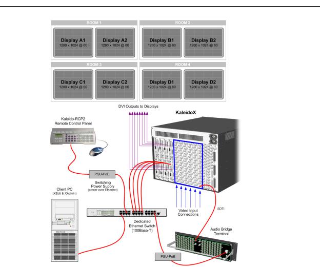
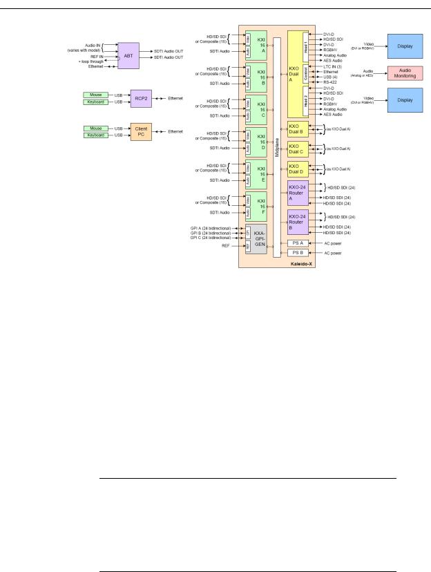
The following diagram shows a basic Kaleido-X (7RU) system configuration, with a single Kaleido-X (7RU) feeding 8 monitor wall displays. The Kaleido-RCP2 (if available) would be located on the production desk, while the Client PC could be anywhere with internet access to the network.
2
Kaleido-X (7RU)
Hardware Description & Installation Manual
The diagram below shows the Kaleido-X multiviewer system and its inputs and outputs. Examples of the various external devices that connect to the multiviewer are also shown.
3
Kaleido-X (7RU) Installation
Mechanical Installation
Kaleido-X (7RU) system block diagram
Mechanical Installation
Unpacking
Make sure the following items have been shipped with your Kaleido-X. If any of these are missing, contact your distributor or Grass Valley.
•Kaleido-X unit, with pre-installed cards and power supplies
•2 AC power cords
•A DVD of system software and documentation
•The Kaleido-X (7RU) Quick Start Guide
•DVD including the Release Notes for the current version of the Kaleido-X software, the Kaleido-X User’s Manual, database samples, Quick Start guides and hardware reference manuals for all multiviewer models
Note: In line with our commitment to environmental preservation, only the Quick Start Guide for your multiviewer model, and some ancillary documents (e.g. welcome letters, warranty cards) are distributed in printed form. All manuals and the Release Notes are available on the DVD that shipped with your multiviewer. See the Documentation section of the Release Notes for a complete list. You can obtain the latest version of the manuals, the Release Notes, as well as software and useful data, from the Software and documentation section of Grass Valley’s support portal.
• Keyboard
4

Kaleido-X (7RU)
Hardware Description & Installation Manual
•Mouse
•Serial port adapters (one with straight cabling and one with crossover cabling for each output card in your multiviewer):
Part number |
Adapter cabling |
RS-422 pinout at the DE-9P connector |
|
|
|
1737-3000-102 |
Straight |
Controller (SMPTE master) mode |
|
|
|
1792-3700-100 |
Crossover |
Tributary (SMPTE slave) mode |
|
|
|
Rack-Mount Installation
A Kaleido-X multiviewer may be installed in a standard 19-inch rack, using the proper screws and washers (not included). The Kaleido-RCP2 Remote Control Panel (optional) may also be installed in a rack using the optional KRCP-RK2 mounting kit.
For proper ventilation, make sure the front and side panel air vents are not blocked and the air filter is clean.
Frame and Electrical Installation
Kaleido-X (7RU) is a self-contained unit consisting of a frame, redundant power supplies, and various input and output cards. The monitor wall displays and external control devices complete the system.
Frame
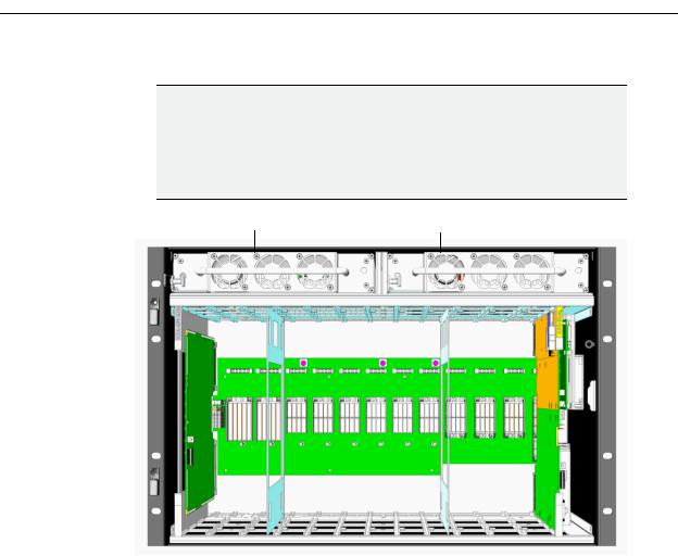
The Kaleido-X (7RU) frame is 7 RU high. It incorporates an internal midplane for interconnecting the cards. Cards are installed from the front of the frame. Each card is associated with input and/or output connectors which are mounted on a connector panel. These connector panels are installed from the rear of the frame, in the same horizontal position as their associated card. The redundant power supplies are installed at the top of the frame.
The hinged front door can be opened to give access to the cards. A removable retaining bar across the front of the frame inside the door holds the cards securely in place.
The Kaleido-X (7RU) frame incorporates the following key elements:
•A rack-mountable mechanical framework
•A side-opening, removable door to cover and protect the front of the frame and the installed cards
•A midplane board that enables inter-card communication
•Slots for installing signal processing cards that plug into the midplane
•Mounting points for rear connector panels
•Redundant power supplies
•Ventilation
The front slots and rear panel connection points are color-coded according to the type of card that can be located in the slot. The extractor handles on the cards are color-coded to
5
Kaleido-X (7RU) Installation
Frame
match. The cards are physically configured so they cannot be installed in the wrong type of slot.
IMPORTANT
Output D / EXP. and Output C are considered the master slots for the Kaleido-X system's internal redundancy process. An output card MUST be present in either Output D / EXP. or Output C, or the system will not start.
Install your output cards starting with Output D / EXP. or Output C, and then
Output B or Output A.
PSU A |
PSU B |
Slot # |
1 |
2 |
3 |
4 |
5 |
6 |
7 |
8 |
9 |
10 |
11 |
12 |
13 |
Function |
Main |
Option Option |
Input |
Input |
Input |
Input |
Input |
Input |
Output |
Output Output |
Output |
||
|
|
A |
B |
A |
B |
C |
D |
E |
F |
A |
B |
C |
D / Exp |
KXA-FR7 frame model
6
Kaleido-X (7RU)
Hardware Description & Installation Manual
|
|
|
|
PSU A |
PSU B |
Slot # |
1 |
2 |
3 |
4 |
5 |
6 |
7 |
8 |
9 |
10 |
11 |
12 |
13 |
Function |
Main |
Option Option |
Input |
Input |
Input |
Input |
Input |
Input |
Output |
Output Output |
Output |
||
|
|
A |
B |
A |
B |
C |
D |
E |
F |
A |
B |
C |
D / Exp |
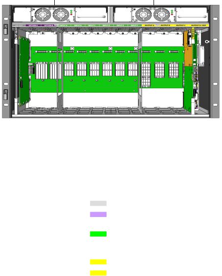
KXA-FR7-B frame model
The illustrations above show the location of the available slots in the frame. From left to right as seen from the front of the frame, the available slots are as follows:
Slot |
Function |
Color code |
Card type |
|
|
|
|
|
|
1 |
Main |
Grey |
|
KXA-GPI-GEN |
|
|
|
|
|
2 - 3 |
Option |
Purple |
|
KXO-24 HD/SD-SDI Router |
|
|
|
|
KXO-24 SD-SDI Router |
|
|
|
|
|
4 - 9 |
Input |
Green |
|
KXI-16HSV3, KXI-16HSV |
|
|
|
|
KXI-16HS3, KXI-16HS |
|
|
|
|
KXI-16SV |
|
|
|
|
|
10 - 12 |
Output |
Yellow |
|
KXO-Dual3, KXO-Dual |
|
|
|
|
|
13 |
Output/Expansion |
Yellow |
|
KXO-Dual3, KXO-Dual, or KXO-EXP |
|
|
|
|
|
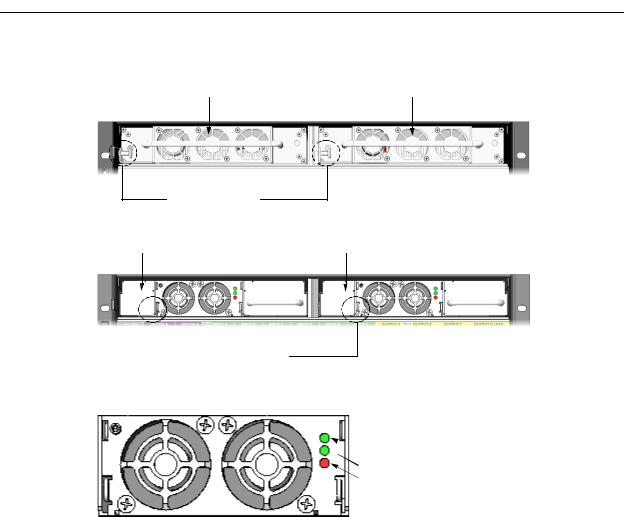
The rear of the frame holds the rear connector panels for the cards, the AC power connectors, and a fan for power-supply cooling.
7

Kaleido-X (7RU) Installation
Frame
Frame cooling  fans
fans
Rear connector  panel
panel
KXA-FR7 frame model
Frame cooling  fans
fans
Rear connector panel
KXA-FR7-B frame model
Monitoring the Temperature of the Kaleido-X
For optimal performance, it is strongly recommended that you operate the Kaleido-X in an environment with an ambient temperature lower than 20 ºC (68 ºF).
IMPORTANT
When measuring the ambient room temperature, take your readings from directly in front of the Kaleido-X frame.
There are two factors that could influence airflow inside the frame:
•altitude
•airflow obstruction at the rear of the unit
8
Kaleido-X (7RU)
Hardware Description & Installation Manual
To monitor airflow efficiency, the Kaleido-X offers on-board probing that monitors the temperature in strategic areas. Use the table, below, to determine whether measured values exceed recommended values.
Monitored values via XAdmin |
Temperature should not exceed |
|
|
Input cards |
75 ºC (167 ºF) |
|
|
Output cards |
83 ºC (181 ºF) |
|
|
Keep in mind that these values are measured at the chip level and should be interpreted as relative indicators of the cards’ internal temperature and of the system’s overall ability to evacuate excess heat, in the context of your specific system configuration.
The vast majority of installations meet these requirements. In the case of multiviewers installed in an environment where cards are prone to exceed the recommended temperature, Grass Valley recommends replacing the standard frame cooling fan assembly with a special fan tray that will help improve the airflow within the equipment rack or cabinet.
The Adapted Fan Tray (part number KXA-FAN-TRAY-1) is compatible with both
Kaleido-X (7RU) frame models (part numbers KXA-FR7, and KXA-FR7-B). It ensures a vertical airflow (as opposed to the standard frame cooling fan assembly whose ventilation exhaust is directed horizontally), and can be mounted in four different configurations:
•Fan assembly on the left, facing up, attached to top side of tray (default configuration)
•Fan assembly on the left, facing down, attached to underside of tray
•Fan assembly on the right, facing down, attached to underside of tray
•Fan assembly on the right, facing up, attached to top side of tray
If measured values exceed recommended values, make the necessary corrections to your installation (please contact Grass Valley Technical Support for the recommended practice).
Power Supplies
The Kaleido-X is powered by dual redundant power supplies. These are installed at the top of the frame above the cards. The supplies are installed and removed from the front of the frame and are hot-swappable, so that a defective supply may be replaced without removing the Kaleido-X from service.
IMPORTANT
There are two different models of 7RU frames, and two models of power supply units. They are not interchangeable.
•If you have a frame model KXA-FR7-B then you need the KXA-PSU-7-B power supply and you must ensure the supply is grounded before connecting your system.
•If you have a frame model KXA-FR7 then you need the KXA-PSU-7 power supply.
9
Kaleido-X (7RU) Installation
Power Supplies
Access the power supplies by opening the front door of the frame. The two power supplies are located at the top, above the card slots. Viewed from the front of the frame, PSU A is located on the left-hand side, and PSU B is located on the right-hand side.
PSU A |
PSU B |
Spring-loaded fasteners
KXA-PSU-7 power supplies on a KXA-FR7 frame
PSU A |
PSU B |
 Spring-loaded fasteners
KXA-PSU-7-B power supplies on a KXA-FR7-B frame
The KXA-PSU-7-B power supply model has three LED indicators:
 AC good (green)
DC good (green)
Fault (red)
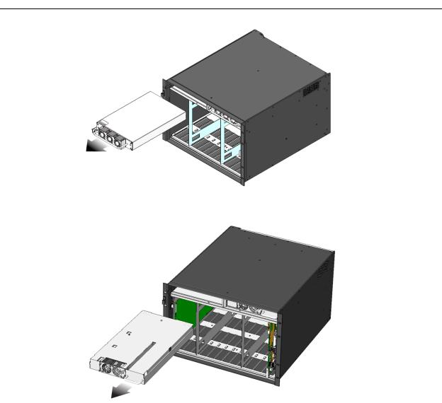
Removing a Power Supply
To remove a power supply
1Open the front door of the frame and locate the two power supplies at the lower right side.
2 Undo the threaded fastener at the upper right side of the supply to be removed.
3Pull on the bracket holding the fastener; it rotates down and becomes a handle for pulling the power supply out of its slot.
10
Kaleido-X (7RU)
Hardware Description & Installation Manual
KXA-PSU-7 removal
KXA-PSU-7-B removal
Installing a Power Supply
To install a power supply
1Position the supply in front of an empty power supply slot in the top front of the frame, with the connector end towards the frame.
2Slide the power supply into the empty slot, moving it gently until it contacts the sockets at the rear of the slot.
3Push firmly but gently on the power supply handle until the power supply's connectors have mated with the frame's sockets, and the power supply will go in no further.
11
Kaleido-X (7RU) Installation
Ventilation
4As the supply reaches its final position, the spring-loaded fastener at the left-hand side of the supply will engage the frame, securing the power supply in place. You may need to pull the fastener out before the supply can be pushed into its final position.
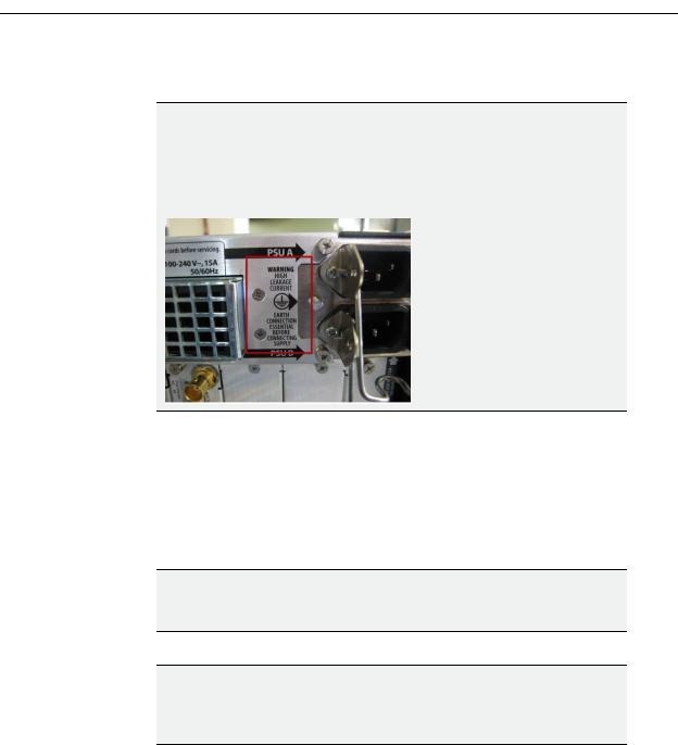
IMPORTANT
There are two different models of 7RU frames, and two models of power supplies.
If you have a frame model KXA-FR7-B (with the corresponding KXA-PSU-7-B power supply), you must ensure that a ground cable (not included) is connected between the frame and the rack before powering up the unit.

 Connect a ground cable between
this stud and the rack
Operation
Separate AC connectors are provided for the two power supplies, and are located at the top right of the rear of the frame. Connect both power supplies to an appropriate power source using the supplied power cords.
•The top power socket is for PSU A.
•The bottom power socket is for PSU B.
CAUTION
There is no ON/OFF switch for the Kaleido-X (7RU).
The multiviewer will start as soon as the power is applied.
IMPORTANT
A fully populated Kaleido-X frame will draw nearly 15 amps of current.
Ensure that the circuit to which the frame is connected can handle that load, and that of any other connected devices.
Ventilation
The Kaleido-X frame is cooled by ventilation fans. Fans are located in key positions within the frame.
12
Kaleido-X (7RU)
Hardware Description & Installation Manual
Frame Cooling Fans
Primary ventilation for the cards installed in the frame is handled by six fans located at the top rear of the frame, behind the power supplies.
IMPORTANT
The Kaleido-X requires a constant flow of cooling air during operation. DO NOT OPERATE THE UNIT IF THE FRAME COOLING FANS ARE NOT WORKING.
To replace a defective fan, see Replacing a Defective Cooling Fan, on page 33.
These fans draw air into the frame through a grille and filter in the front door, and exhaust it through the grate on the rear of the fan assembly.
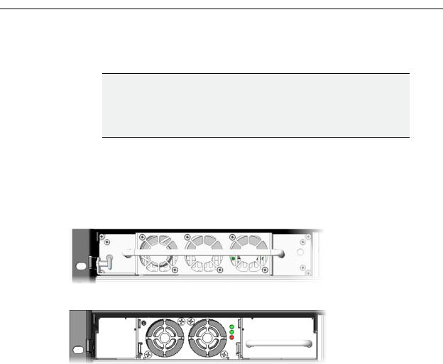
Power Supply Cooling Fans
Each power supply has two (KXA-PSU-7) or three (KXA-PSU-7-B) fans located on the front of the supply (behind the extraction handle, in the case of the KXA-PSU-7 power supply).
KXA-PSU-7 power supply
KXA-PSU-7-B power supply
Card Cooling Fans
Some of the cards in the Kaleido-X system are equipped with on-board fans to ensure proper cooling of key components. These fans focus the air flow provided by the frame cooling fans.
Card |
On-board fans |
|
|
Output (KXO) card |
4 |
|
|
Router card |
2 |
|
|
Input (KXI-16) card |
4 |
|
|
GPI/genlock card |
0 |
|
|
Air Filter
Cooling air drawn into the Kaleido-X frame by the ventilating fans passes through a filter located behind a grille in the front door of the frame. To clean the air filter, see Cleaning the Air Filter, on page 32.
13

Kaleido-X (7RU) Installation
Card Installation and Replacement
Card Installation and Replacement
This section describes the installation of rear connector panels and cards in the Kaleido-X frame.
Installing a Rear Connector Panel
To install a rear connector panel
1Remove the blank rear panel or the rear panel from the previously-installed card, using a screwdriver to loosen the two captive screws.
2Position the new rear panel in the vacant location so its connectors are aligned with the corresponding plugs, and push it gently into place so the connectors mate.
3 Secure the panel in place, using a screwdriver to tighten the two captive screws.
Removing a Card
To remove a card
1 Open the front door of the frame and locate the card to be removed.
2Remove the card retaining bar by unscrewing the captive screw on the right side, and pulling it out of the slot at the left side.
3Pull the ends of the two extractor handles out and away from the center of the card, levering it out of its connector.
4 Grasp the extractor handles, and pull the card gently straight out of the slot.
Installing a Card
To install a card
1Open the front door of the frame and locate an empty slot appropriate for the card type.
Note: The cards are mechanically configured so that it is not possible to install a card in the wrong slot.
2Remove the card retaining bar by unscrewing the captive screw on the right side, and pulling it out of the slot at the left side.
3Orient the card so that the labelled and color-coded extractor handle is at the top and the connectors are toward the frame.
4 Slide the card all the way into the slot until it touches the connectors.
5Push gently on the extractor handles until the connectors mate and the card is completely into the slot.
6Install the card retaining bar by slipping it into the slot on the left side of the frame and fastening the captive screw on the right side.
14
Kaleido-X (7RU)
Hardware Description & Installation Manual
Kaleido-X Cards
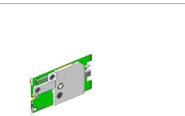
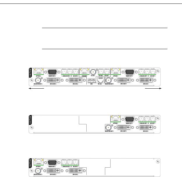
KXO-Dual Output Cards
The KXO-Dual and KXO-Dual3 cards are output cards that can be installed in a Kaleido-X multiviewer. They are dual-head output cards, meaning that they support two independent outputs. These outputs, called Head 1 and Head 2, are each provided with a complete set of connectors.
The KXO-Dual and KXO-Dual3 are multi-function cards that perform a significant portion of the signal processing required to create the monitor wall output. They incorporate a mezzanine card mounted on the component side. Each output card is complemented by a rear panel (KXO-Dual-R) that holds all input and output connectors associated with the card.
Output cards can be installed in any of the four available OUTPUT slots inside a Kaleido-X frame. These slots are color-coded YELLOW on the front and rear panel of the frame.
A Kaleido-X frame must contain at least one output card. In systems with more cards, one card is considered the master card, and the others are slaves, from a processing point of view.
One card must always be present in either the Output C slot or the Output D / EXP. slot to ensure proper operation of the system.
•If the only card in the frame is in Output C, then it can only be an output card (KXODual3 or KXO-Dual).
•If the only card in the frame is in Output D / EXP., then it can be an output card (KXODual3 or KXO-Dual) or an expansion card (KXO-EXP).
•If both slots Output C and Output D / EXP. are occupied, the card in Output D / EXP. becomes the hardware master.
•If the card in Output D / EXP. is removed, the card in Output C will assume the hardware master role automatically.
In addition, there is always one output card designated as the software master (i.e. the card that has the frame’s IP address). In XAdmin, you can identify which output card is the current software master, by looking for the card with the word “master” next to its identifier (refer to the Administration and Servicing chapter, in the Kaleido-X User’s Manual, for more
15

Kaleido-X (7RU) Installation
KXO-Dual Output Cards
information). At startup, the software master role is assumed by the first output card found in the multiviewer, based on the following rules:
•For a simple Kaleido-X (7RU) system: first output card found, starting from Output D / EXP., then Output C, Output B, and finally Output A.
•For an expansion system: first output card found, starting from Frame A, Output C, B, and A, and then Frame B, Output C, B, and A, in this sequence.
•If at any time, the master card is removed, a new master is designated, based on the same rules.
•If a slave card is removed, the master remains unchanged.
•If an output card is added to a system that did not have any so far, the new output card becomes the master.
•If an output card is added to a system that already has at least one output card, the new card is a slave.
In the case of an expansion system’s initial configuration, there must be an output card in Output C of Frame A (see Kaleido-X (14RU) Expansion, on page 35 for details). This card will start as the software master for the whole expansion system, but any other output card in the system may later become the master (for example, when you remove or reseat this card from Frame A Output C).
Notes
•Be careful to install the rear panel in the matching location at the rear of the frame.
•The card and its rear panel can be installed in any order.
•These cards are hot-swappable; it is not necessary to turn off the Kaleido-X when installing or replacing cards.
•If a software master card loses network connectivity while remaining seated in its slot, then none of the other cards will take over and the multiviewer will be unavailable on the network until the connectivity issue is resolved.
Every output card is connected to the other cards in the Kaleido-X frame through the frame’s internal midplane.
External connections to the card are made through connectors that are found in two locations:
•on the rear panel (see Rear Panel Connections below)
•on the front card edge (see Front Card-Edge Layout, on page 19)
HD-SDI Monitoring Output Option
The output cards provide support for HD-SDI monitoring output in 720p, 1080i or 1080p (available with the optional KXO-HDM mezzanine).
•KXO-Dual: If the KXO-HDM mezzanine is installed on a KXO-Dual card, the only HD-SDI output formats supported are 720p and 1080i.
16
Kaleido-X (7RU)
Hardware Description & Installation Manual
•KXO-Dual3: For a KXO-Dual3 card, the scan format is set with the associated displays’ configuration, in XEdit. Refer to the Rooms chapter, in the Kaleido-X User’s Manual, for details.
Note: To install a KXO-HDM mezzanine on an existing KXO-Dual or KXODual3 card, refer to the KXO-HDM Installation Instructions, for details. This document is available from Grass Valley’s support portal, and on the DVD that shipped with your system.
Rear Panel Connections
The rear panel layout is divided into three areas: Head 1, Head 2, and Control.
Bottom of panel |
Top of panel |
Head 1
The connectors located at the top of the rear panel (right-hand side when the card is horizontal and you can read the connector labels normally) are the Head 1 connectors.
Head 2
The connectors located at the bottom of the rear panel (left-hand side when the card is horizontal and you can read the connector labels normally) are the Head 2 connectors.
Control
The connectors located in the middle of the rear panel are control connectors.
The following table lists the function of each connector associated with the output heads.
Connector label |
|
Connector |
|
|
|
|
|
Head 1 |
Head 2 |
type |
Function |
|
|
|
|
HD/SD SDI OUT 1 |
HD/SD SDI OUT 2 |
BNC |
Serial digital HD output signal for |
|
|
|
monitoring purposes |
|
|
|
|
DVI IN 1 |
DVI IN 2 |
DVI |
DVI input signal that can be used as a |
|
|
|
background in the monitor wall display in |
|
|
|
place of the internally-generated |
|
|
|
background |
|
|
|
|
17

Kaleido-X (7RU) Installation
KXO-Dual Output Cards
|
|
|
|
|
|
|
|
|
|
|
|
|
|
|
|
Connector label |
|
Connector |
|
|
|
|
|
|
|
Head 1 |
Head 2 |
type |
Function |
|
|
|
|
|
|
DVI-D OUT 1 |
DVI-D OUT 2 |
DVI |
DVI digital output (no analog signal on this |
|
|
|
|
connector) |
|
|
|
|
|
|
RGBHV OUT 1 |
RGBHV OUT 2 |
DE-15S |
High-resolution analog component output |
|
|
|
|
to feed the monitor wall display |
|
|
|
|
|
|
ANALOG OUT 1 L |
ANALOG OUT 2 L |
WECO |
Analog audio output (left channel) to feed |
|
|
|
|
the audio monitoring system |
|
|
|
|
|
|
ANALOG OUT 1 R |
ANALOG OUT 2 R |
WECO |
Analog audio output (right channel) to |
|
|
|
|
feed the audio monitoring system |
|
|
|
|
|
|
AES OUT 1 |
AES OUT 2 |
WECO |
Digital audio output (AES) to feed the audio |
|
|
|
|
monitoring system |
|
|
|
|
|
|
OPTION 1 |
OPTION 2 |
RJ-45 |
(for future use) |
|
|
|
|
|
The following table lists the purpose of each connector associated with card control.
Connector label |
Connector type |
Function |
|
|
|
LTC IN 1 |
BNC |
Time code input #1 |
|
|
|
LTC IN 2 |
WECO |
Time code input #2 |
|
|
|
LTC IN 3 |
WECO |
Time code input #3 |
|
|
|
ETHERNET |
RJ-45 |
100 Base-T Ethernet connection |
|
|
|
USB |
USB A |
Connect a mouse, keyboard, or USB key for software |
|
|
upgrade or data backup |
|
|
There are three other USB ports accessible on the front of |
|
|
the card that serve the same functions. |
|
|
|
RS-422 |
RJ-45 (see note |
Connect to an RS-422 (SMPTE ST 207, EBU-3245) or |
|
below) |
RS-485 device or network |
|
|
|
Note: The Kaleido-X’s RS-422 ports have an RJ-45 connector in order to preserve space on a busy panel. The RS-422 interface specifies a DE-9 connector, so if you are using this interface, you will require a DE-9-to-RJ-45 adapter. Grass Valley supplies two adapter models, correctly wired for this application: a straight adapter (part no. 1737-3000-102), and a crossover adapter (part no. 1792-3700-100).
The pinout for the RS-422 signal on the RJ-45 connector on the output cards’ rear panel, and the wiring diagram for an appropriate adapters, are shown here:
18
Loading...