


 Loading...
CR Series
Compact Routers and Control Panels
User’s Guide
UG1600-14
2 Dec 2014

Copyright & Trademark Notice
Copyright © 2014 Grass Valley. All rights reserved.
Belden, Belden Sending All The Right Signals, and the Belden logo are trademarks or registered trademarks of Belden Inc. or its affiliated companies in the United States and other jurisdictions. Grass Valley, NVISION, NV9000, CR6400, and CR Series are trademarks or registered trademarks of Grass Valley. Belden Inc., Grass Valley, and other parties may also have trademark rights in other terms used herein.
Terms and Conditions
Please read the following terms and conditions carefully. By using CR Series documentation, you agree to the following terms and conditions.
Grass Valley hereby grants permission and license to owners of CR Series routers to use their product manuals for their own internal business use. Manuals for Grass Valley products may not be reproduced or transmitted in any form or by any means, electronic or mechanical, including photocopying and recording, for any purpose unless specifically authorized in writing by Grass Valley.
A Grass Valley manual may have been revised to reflect changes made to the product during its manufacturing life. Thus, different versions of a manual may exist for any given product. Care should be taken to ensure that one obtains the proper manual version for a specific product serial number.
Information in this document is subject to change without notice and does not represent a commitment on the part of Grass Valley.
Warranty information is available in the support section of the Grass Valley web site (www.grassvalley.com).
Title |
CR Series Routers User’s Guide |
Part Number |
UG1600-14 |
Revision |
3.2 (02 Dec 14) |
ii
|
|
|
|
|
CR Series |
|
|
|
|
|
User’s Guide |
|
|
|
|
|
|
|
Change History |
|
|
||
|
|
|
|
|
|
|
Rev. |
Date |
ECO |
Description |
Approved |
|
|
|
|
|
|
|
1.0 |
03 Apr 06 |
— |
Initial Release |
— |
|
|
|
|
|
|
|
1.1 |
14 Nov 06 |
12390 |
Added material regarding -AES routers, 32×32 |
D. Cox |
|
|
|
|
routers, network operation, 16×4 router, and 16×4 |
|
|
|
|
|
and 16×2 control panels. Corrected a few problems. |
|
|
|
|
|
|
|
|
1.2 |
04 Jan 07 |
12440 |
Added material regarding -AV routers, remote panel |
D. Cox |
|
|
|
|
modules, CrConfig (software), and compact router |
|
|
|
|
|
networks. |
|
|
|
|
|
Created button legend templates. |
|
|
|
|
|
|
|
|
1.3 |
12 Jul 07 |
13355 |
Added material regarding analog audio routers, |
D. Cox |
|
|
|
|
machine control routers, and “3Gig” routers. |
|
|
|
|
|
Automation is now possible. |
|
|
|
|
|
|
|
|
1.4 |
19 Nov 08 |
14426 |
References the CRSC software. Includes new CR |
D. Cox |
|
|
|
|
Series products. Misc. corrections. |
|
|
|
|
|
|
|
|
1.5 |
30 Mar 09 |
15703 |
Format change. |
D. Cox |
|
|
|
|
|
|
|
1.6 |
12 Oct 09 |
16114 |
Added new CR Series products, NV9000 support. |
D. Cox |
|
|
|
|
|
|
|
2.0 |
22 Mar 10 |
16912 |
Added CQX series. |
D. Cox |
|
|
|
|
|
|
|
2.1 |
04 May 10 |
16993 |
Added ±3-line buffer. |
D. Cox |
|
|
|
|
|
|
|
2.2 |
18 Aug 10 |
17186 |
Short addition regarding 3-line buffer. |
D. Cox |
|
|
|
|
|
|
|
2.3 |
30 Mar 12 |
17286 |
Added 3Gig routers |
D. Cox |
|
|
|
|
|
|
|
2.4 |
15 Nov 13 |
19037 |
Improvements to CQX series. |
D.Cox |
|
|
|
|
|
|
|
3.0 |
28 May 14 |
19241 |
Added new CR6400 family products. |
D.Cox |
|
|
|
|
|
|
|
3.2 |
03 Oct 14 |
19332 |
Phase 2 of CR6400 products. |
D.Cox |
|
|
|
|
|
|
|
3.2 |
02 Dec 14 |
19357 |
New contacts. |
D.Cox |
|
|
|
|
|
|
 FCC Statement
This equipment has been tested and found to comply with the limits for a Class A digital device, pursuant to part 15 of the FCC Rules. These limits are designed to provide reasonable protection against harmful interference when the equipment is operated in a commercial environment. This equipment generates, uses, and can radiate radio frequency energy and, if not installed and used in accordance with the instruction manual, may cause harmful interference to radio communications. Operation of this equipment in a residential area is likely to cause harmful interference in which case the user will be required to correct the interference at his own expense.

 Declaration of Conformance (CE)
All of the equipment described in this manual has been designed to conform with the required safety and emissions standards of the European Community. Products tested and verified to meet these standards are marked as required by law with the CE mark.
When shipped into member countries of the European Community, this equipment is accompanied by authentic copies of original Declarations of Conformance on file in Grass Valley offices in Grass Valley, California USA.
iii

Software License Agreement and Warranty Information
Contact Grass Valley for details on the software license agreement and product warranty.
Important Safeguards and Notices
This section provides important safety guidelines for operators and service personnel. Specific warnings and cautions appear throughout the manual where they apply. Please read and follow this important information, especially those instructions related to the risk of electric shock or injury to persons.
WARNING
Any instructions in this manual that require opening the equipment cover or enclosure are for use by qualified service personnel only. To reduce the risk of electric shock, do not perform any service other than that contained in the operating instructions unless you are qualified to do so.
Restriction on Hazardous Substances (RoHs)
Grass Valley is in compliance with EU Directive RoHS 2002/95/EC governing the restricted use of certain hazardous substances and materials in products and in our manufacturing processes.
Grass Valley has a substantial program in place for RoHS compliance that includes significant investment in our manufacturing process, and a migration of Grass Valley product electronic components and structural materials to RoHS compliance.
It is our objective to maintain compliance with all relevant environmental and product regulatory requirements. Detailed information on specific products or on the RoHS program at Grass Valley is available from Grass Valley Customer Support at
1-800-719-1900 (toll-free) or 1-530-265-1000 (outside the U.S.).
iv
CR Series
User’s Guide
Symbols and Their Meanings
The lightning flash with arrowhead symbol within an equilateral triangle alerts the user to the presence of dangerous voltages within the product’s enclosure that may be of sufficient magnitude to constitute a risk of electric shock to persons.
The exclamation point within an equilateral triangle alerts the user to the presence of important operating and maintenance/service instructions.
The Ground symbol represents a protective grounding terminal. Such a terminal must be connected to earth ground prior to making any other connections to the equipment.
The fuse symbol indicates that the fuse referenced in the text must be replaced with one having the ratings indicated.
The presence of this symbol in or on Grass Valley equipment means that it has been designed, tested and certified as complying with applicable Underwriter’s Laboratory (USA) regulations and recommendations.
The presence of this symbol in or on Grass Valley equipment means that it has been designed, tested and certified as essentially complying with all applicable European Union (CE) regulations and recommendations.
General Warnings
A warning indicates a possible hazard to personnel which may cause injury or death. Observe the following general warnings when using or working on this equipment:
•Heed all warnings on the unit and in the operating instructions.
•Do not use this equipment in or near water.
•This equipment is grounded through the grounding conductor of the power cord. To avoid electrical shock, plug the power cord into a properly wired receptacle before connecting the equipment inputs or outputs.
•Route power cords and other cables so they are not likely to be damaged.
•Disconnect power before cleaning the equipment. Do not use liquid or aerosol cleaners; use only a damp cloth.
•Dangerous voltages may exist at several points in this equipment. To avoid injury, do not touch exposed connections and components while power is on.
v

•Do not wear rings or wristwatches when troubleshooting high current circuits such as the power supplies.
•To avoid fire hazard, use only the specified fuse(s) with the correct type number, voltage and current ratings as referenced in the appropriate locations in the service instructions or on the equipment. Always refer fuse replacements to qualified service personnel.
•To avoid explosion, do not operate this equipment in an explosive atmosphere.
•Have qualified service personnel perform safety checks after any service.
General Cautions
A caution indicates a possible hazard to equipment that could result in equipment damage. Observe the following cautions when operating or working on this equipment:
•When installing this equipment, do not attach the power cord to building surfaces.
•To prevent damage to equipment when replacing fuses, locate and correct the problem that caused the fuse to blow before re-applying power.
•Use only the specified replacement parts.
•Follow static precautions at all times when handling this equipment.
•This product should only be powered as described in the manual. To prevent equipment damage, select the proper line voltage on the power supply(ies) as described in the installation documentation.
•To prevent damage to the equipment, read the instructions in the equipment manual for proper input voltage range selection.
•Some products include a backup battery. There is a risk of explosion if the battery is replaced by a battery of an incorrect type. Dispose of batteries according to instructions.
•Products that have (1) no on/off switch and (2) use an external power supply must be installed in proximity to a main power outlet that is easily accessible.
vi

Table of Contents
1 Preface . . . . . . . . . . . . . . . . . . . . . . . . . . . . . . . . . . . . . . . . . . . . . . . . 1
Chapter Structure . . . . . . . . . . . . . . . . . . . . . . . . . . . . . . . . . . . . . . . . . . . . . . . . . . . . . . . . . . . . . . . . . . . . . . . . . . . . . . 1
The PDF Document . . . . . . . . . . . . . . . . . . . . . . . . . . . . . . . . . . . . . . . . . . . . . . . . . . . . . . . . . . . . . . . . . . . . . . . . . . . . . 1
Terms, Conventions and Abbreviations . . . . . . . . . . . . . . . . . . . . . . . . . . . . . . . . . . . . . . . . . . . . . . . . . . . . . . . . . . 2
2 Introduction . . . . . . . . . . . . . . . . . . . . . . . . . . . . . . . . . . . . . . . . . . . 3
Overview . . . . . . . . . . . . . . . . . . . . . . . . . . . . . . . . . . . . . . . . . . . . . . . . . . . . . . . . . . . . . . . . . . . . . . . . . . . . . . . . . . . . . . . 3 Summary . . . . . . . . . . . . . . . . . . . . . . . . . . . . . . . . . . . . . . . . . . . . . . . . . . . . . . . . . . . . . . . . . . . . . . . . . . . . . . . . . . 3 Routers . . . . . . . . . . . . . . . . . . . . . . . . . . . . . . . . . . . . . . . . . . . . . . . . . . . . . . . . . . . . . . . . . . . . . . . . . . . . . . . 5 Control Panels. . . . . . . . . . . . . . . . . . . . . . . . . . . . . . . . . . . . . . . . . . . . . . . . . . . . . . . . . . . . . . . . . . . . . . . . . 5 Remote Panel Modules . . . . . . . . . . . . . . . . . . . . . . . . . . . . . . . . . . . . . . . . . . . . . . . . . . . . . . . . . . . . . . . . 6 Usage . . . . . . . . . . . . . . . . . . . . . . . . . . . . . . . . . . . . . . . . . . . . . . . . . . . . . . . . . . . . . . . . . . . . . . . . . . . . . . . . . 6 Software . . . . . . . . . . . . . . . . . . . . . . . . . . . . . . . . . . . . . . . . . . . . . . . . . . . . . . . . . . . . . . . . . . . . . . . . . . . . . . 9 Benefits . . . . . . . . . . . . . . . . . . . . . . . . . . . . . . . . . . . . . . . . . . . . . . . . . . . . . . . . . . . . . . . . . . . . . . . . . . . . . . . 9 The Routers . . . . . . . . . . . . . . . . . . . . . . . . . . . . . . . . . . . . . . . . . . . . . . . . . . . . . . . . . . . . . . . . . . . . . . . . . . . . . . . . 9 CR6400 Routers . . . . . . . . . . . . . . . . . . . . . . . . . . . . . . . . . . . . . . . . . . . . . . . . . . . . . . . . . . . . . . . . . . . . . . . 9 Other CR Series Routers. . . . . . . . . . . . . . . . . . . . . . . . . . . . . . . . . . . . . . . . . . . . . . . . . . . . . . . . . . . . . . . . 9 Digital Video Routers . . . . . . . . . . . . . . . . . . . . . . . . . . . . . . . . . . . . . . . . . . . . . . . . . . . . . . . . . . . . . . . . . 12 CQX Video Routers . . . . . . . . . . . . . . . . . . . . . . . . . . . . . . . . . . . . . . . . . . . . . . . . . . . . . . . . . . . . . . . . . . . 13 CR6400 Routers . . . . . . . . . . . . . . . . . . . . . . . . . . . . . . . . . . . . . . . . . . . . . . . . . . . . . . . . . . . . . . . . . . . . . . 16 Analog Video Routers . . . . . . . . . . . . . . . . . . . . . . . . . . . . . . . . . . . . . . . . . . . . . . . . . . . . . . . . . . . . . . . . 17 Digital Audio Routers . . . . . . . . . . . . . . . . . . . . . . . . . . . . . . . . . . . . . . . . . . . . . . . . . . . . . . . . . . . . . . . . 18 Analog Audio Routers . . . . . . . . . . . . . . . . . . . . . . . . . . . . . . . . . . . . . . . . . . . . . . . . . . . . . . . . . . . . . . . . 19 Machine Control Routers . . . . . . . . . . . . . . . . . . . . . . . . . . . . . . . . . . . . . . . . . . . . . . . . . . . . . . . . . . . . . 20 The Control Panels . . . . . . . . . . . . . . . . . . . . . . . . . . . . . . . . . . . . . . . . . . . . . . . . . . . . . . . . . . . . . . . . . . . . . . . . 21 1RU Panels . . . . . . . . . . . . . . . . . . . . . . . . . . . . . . . . . . . . . . . . . . . . . . . . . . . . . . . . . . . . . . . . . . . . . . . . . . . 21 CQX Panel. . . . . . . . . . . . . . . . . . . . . . . . . . . . . . . . . . . . . . . . . . . . . . . . . . . . . . . . . . . . . . . . . . . . . . . . . . . . 22 2RU Panels . . . . . . . . . . . . . . . . . . . . . . . . . . . . . . . . . . . . . . . . . . . . . . . . . . . . . . . . . . . . . . . . . . . . . . . . . . . 22 The Remote Panel Modules. . . . . . . . . . . . . . . . . . . . . . . . . . . . . . . . . . . . . . . . . . . . . . . . . . . . . . . . . . . . . . . . 24
Features . . . . . . . . . . . . . . . . . . . . . . . . . . . . . . . . . . . . . . . . . . . . . . . . . . . . . . . . . . . . . . . . . . . . . . . . . . . . . . . . . . . . . . . 25 Routers . . . . . . . . . . . . . . . . . . . . . . . . . . . . . . . . . . . . . . . . . . . . . . . . . . . . . . . . . . . . . . . . . . . . . . . . . . . . . . . . . . . 25 1RU Routers . . . . . . . . . . . . . . . . . . . . . . . . . . . . . . . . . . . . . . . . . . . . . . . . . . . . . . . . . . . . . . . . . . . . . . . . . 26 CQX Routers . . . . . . . . . . . . . . . . . . . . . . . . . . . . . . . . . . . . . . . . . . . . . . . . . . . . . . . . . . . . . . . . . . . . . . . . . 30 2RU Routers . . . . . . . . . . . . . . . . . . . . . . . . . . . . . . . . . . . . . . . . . . . . . . . . . . . . . . . . . . . . . . . . . . . . . . . . . . 31 Control Panels . . . . . . . . . . . . . . . . . . . . . . . . . . . . . . . . . . . . . . . . . . . . . . . . . . . . . . . . . . . . . . . . . . . . . . . . . . . . 36 CP6464 . . . . . . . . . . . . . . . . . . . . . . . . . . . . . . . . . . . . . . . . . . . . . . . . . . . . . . . . . . . . . . . . . . . . . . . . . . . . . . 37 Other CR Series Panels . . . . . . . . . . . . . . . . . . . . . . . . . . . . . . . . . . . . . . . . . . . . . . . . . . . . . . . . . . . . . . . . 38 Characteristics of Panels in CRSC Systems . . . . . . . . . . . . . . . . . . . . . . . . . . . . . . . . . . . . . . . . . . . . . 39 Characteristics Common to Both Systems . . . . . . . . . . . . . . . . . . . . . . . . . . . . . . . . . . . . . . . . . . . . . 39 1RU Control Panels . . . . . . . . . . . . . . . . . . . . . . . . . . . . . . . . . . . . . . . . . . . . . . . . . . . . . . . . . . . . . . . . . . . 40 CQX Control Panel. . . . . . . . . . . . . . . . . . . . . . . . . . . . . . . . . . . . . . . . . . . . . . . . . . . . . . . . . . . . . . . . . . . . 41 2RU Control Panel . . . . . . . . . . . . . . . . . . . . . . . . . . . . . . . . . . . . . . . . . . . . . . . . . . . . . . . . . . . . . . . . . . . . 42 Remote Panel Modules . . . . . . . . . . . . . . . . . . . . . . . . . . . . . . . . . . . . . . . . . . . . . . . . . . . . . . . . . . . . . . . . . . . 44 1RU Remote Panel Module. . . . . . . . . . . . . . . . . . . . . . . . . . . . . . . . . . . . . . . . . . . . . . . . . . . . . . . . . . . . 44 2RU Remote Panel Module. . . . . . . . . . . . . . . . . . . . . . . . . . . . . . . . . . . . . . . . . . . . . . . . . . . . . . . . . . . . 45 CRSC . . . . . . . . . . . . . . . . . . . . . . . . . . . . . . . . . . . . . . . . . . . . . . . . . . . . . . . . . . . . . . . . . . . . . . . . . . . . . . . . . . . . . 45
vii

Table of Contents
3 Installation. . . . . . . . . . . . . . . . . . . . . . . . . . . . . . . . . . . . . . . . . . . . 47
Package Contents . . . . . . . . . . . . . . . . . . . . . . . . . . . . . . . . . . . . . . . . . . . . . . . . . . . . . . . . . . . . . . . . . . . . . . . . . . . . . 47 Design Considerations . . . . . . . . . . . . . . . . . . . . . . . . . . . . . . . . . . . . . . . . . . . . . . . . . . . . . . . . . . . . . . . . . . . . . . . . . 48 Stand-Alone Router . . . . . . . . . . . . . . . . . . . . . . . . . . . . . . . . . . . . . . . . . . . . . . . . . . . . . . . . . . . . . . . . . . . . . . . 48 Stand-Alone Network . . . . . . . . . . . . . . . . . . . . . . . . . . . . . . . . . . . . . . . . . . . . . . . . . . . . . . . . . . . . . . . . . . . . . 48 CRSC Network. . . . . . . . . . . . . . . . . . . . . . . . . . . . . . . . . . . . . . . . . . . . . . . . . . . . . . . . . . . . . . . . . . . . . . . . . . . . . 48 CQX Routers . . . . . . . . . . . . . . . . . . . . . . . . . . . . . . . . . . . . . . . . . . . . . . . . . . . . . . . . . . . . . . . . . . . . . . . . . . . . . . 49 CR6400 Routers . . . . . . . . . . . . . . . . . . . . . . . . . . . . . . . . . . . . . . . . . . . . . . . . . . . . . . . . . . . . . . . . . . . . . . . . . . . 49 Router Control Systems. . . . . . . . . . . . . . . . . . . . . . . . . . . . . . . . . . . . . . . . . . . . . . . . . . . . . . . . . . . . . . . . . . . . 49 Rack Mount . . . . . . . . . . . . . . . . . . . . . . . . . . . . . . . . . . . . . . . . . . . . . . . . . . . . . . . . . . . . . . . . . . . . . . . . . . . . . . . . . . . 49 CR6400 Routers . . . . . . . . . . . . . . . . . . . . . . . . . . . . . . . . . . . . . . . . . . . . . . . . . . . . . . . . . . . . . . . . . . . . . . . . . . . 49 Other Routers . . . . . . . . . . . . . . . . . . . . . . . . . . . . . . . . . . . . . . . . . . . . . . . . . . . . . . . . . . . . . . . . . . . . . . . . . . . . . 51 Installing Software . . . . . . . . . . . . . . . . . . . . . . . . . . . . . . . . . . . . . . . . . . . . . . . . . . . . . . . . . . . . . . . . . . . . . . . . . . . . . 53 Installing CRSC . . . . . . . . . . . . . . . . . . . . . . . . . . . . . . . . . . . . . . . . . . . . . . . . . . . . . . . . . . . . . . . . . . . . . . . . . . . . 53 Creating a Router Network . . . . . . . . . . . . . . . . . . . . . . . . . . . . . . . . . . . . . . . . . . . . . . . . . . . . . . . . . . . . . . . . . . . . . 54 Network Considerations . . . . . . . . . . . . . . . . . . . . . . . . . . . . . . . . . . . . . . . . . . . . . . . . . . . . . . . . . . . . . . . . . . . 55 CR6400 Stand-Alone Networks . . . . . . . . . . . . . . . . . . . . . . . . . . . . . . . . . . . . . . . . . . . . . . . . . . . . . . . . . . . . 55 Levels and IP Addresses in CR6400 Stand-Alone Networks . . . . . . . . . . . . . . . . . . . . . . . . . . . . . 55 Stand-Alone Networks for Other CR Series Routers . . . . . . . . . . . . . . . . . . . . . . . . . . . . . . . . . . . . . . . . . 56 Levels and IP Addresses in Stand-Alone Networks . . . . . . . . . . . . . . . . . . . . . . . . . . . . . . . . . . . . . 56 CRSC Networks. . . . . . . . . . . . . . . . . . . . . . . . . . . . . . . . . . . . . . . . . . . . . . . . . . . . . . . . . . . . . . . . . . . . . . . . . . . . 57 Levels and IP Addresses in CRSC Networks . . . . . . . . . . . . . . . . . . . . . . . . . . . . . . . . . . . . . . . . . . . . 57 I/O connections . . . . . . . . . . . . . . . . . . . . . . . . . . . . . . . . . . . . . . . . . . . . . . . . . . . . . . . . . . . . . . . . . . . . . . 58
CQX Networks . . . . . . . . . . . . . . . . . . . . . . . . . . . . . . . . . . . . . . . . . . . . . . . . . . . . . . . . . . . . . . . . . . . . . . . . . . . . 58 Mode Rotary Switch . . . . . . . . . . . . . . . . . . . . . . . . . . . . . . . . . . . . . . . . . . . . . . . . . . . . . . . . . . . . . . . . . . 59 Frame ID Rotary Switch . . . . . . . . . . . . . . . . . . . . . . . . . . . . . . . . . . . . . . . . . . . . . . . . . . . . . . . . . . . . . . . 59 NV9000 Networks . . . . . . . . . . . . . . . . . . . . . . . . . . . . . . . . . . . . . . . . . . . . . . . . . . . . . . . . . . . . . . . . . . . . . . . . . 60 Levels and IP Addresses in NV9000 Networks . . . . . . . . . . . . . . . . . . . . . . . . . . . . . . . . . . . . . . . . . 61 I/O connections . . . . . . . . . . . . . . . . . . . . . . . . . . . . . . . . . . . . . . . . . . . . . . . . . . . . . . . . . . . . . . . . . . . . . . 62
Setting Up Your Configuration PC . . . . . . . . . . . . . . . . . . . . . . . . . . . . . . . . . . . . . . . . . . . . . . . . . . . . . . . . . . . . . . 62 Multiple Subnets . . . . . . . . . . . . . . . . . . . . . . . . . . . . . . . . . . . . . . . . . . . . . . . . . . . . . . . . . . . . . . . . . . . . . . . . . . 64 Power-Up. . . . . . . . . . . . . . . . . . . . . . . . . . . . . . . . . . . . . . . . . . . . . . . . . . . . . . . . . . . . . . . . . . . . . . . . . . . . . . . . . . . . . . 65 Testing . . . . . . . . . . . . . . . . . . . . . . . . . . . . . . . . . . . . . . . . . . . . . . . . . . . . . . . . . . . . . . . . . . . . . . . . . . . . . . . . . . . . . . . . 65 Stand-Alone Routers (including CR6400 Routers) . . . . . . . . . . . . . . . . . . . . . . . . . . . . . . . . . . . . . . . . . . . 65 CR6400 Stand-Alone Networks . . . . . . . . . . . . . . . . . . . . . . . . . . . . . . . . . . . . . . . . . . . . . . . . . . . . . . . . . . . . 66 General Stand-Alone Networks . . . . . . . . . . . . . . . . . . . . . . . . . . . . . . . . . . . . . . . . . . . . . . . . . . . . . . . . . . . . 67 Further Testing . . . . . . . . . . . . . . . . . . . . . . . . . . . . . . . . . . . . . . . . . . . . . . . . . . . . . . . . . . . . . . . . . . . . . . . 67 CRSC Network. . . . . . . . . . . . . . . . . . . . . . . . . . . . . . . . . . . . . . . . . . . . . . . . . . . . . . . . . . . . . . . . . . . . . . . . . . . . . 67 Simple Testing with CRSC. . . . . . . . . . . . . . . . . . . . . . . . . . . . . . . . . . . . . . . . . . . . . . . . . . . . . . . . . . . . . 68 Further Testing . . . . . . . . . . . . . . . . . . . . . . . . . . . . . . . . . . . . . . . . . . . . . . . . . . . . . . . . . . . . . . . . . . . . . . . 68 CQX Routers . . . . . . . . . . . . . . . . . . . . . . . . . . . . . . . . . . . . . . . . . . . . . . . . . . . . . . . . . . . . . . . . . . . . . . . . . . . . . . 68 Basic Functions. . . . . . . . . . . . . . . . . . . . . . . . . . . . . . . . . . . . . . . . . . . . . . . . . . . . . . . . . . . . . . . . . . . . . . . 69 Bypass Functions . . . . . . . . . . . . . . . . . . . . . . . . . . . . . . . . . . . . . . . . . . . . . . . . . . . . . . . . . . . . . . . . . . . . . 69 GPIO Functions. . . . . . . . . . . . . . . . . . . . . . . . . . . . . . . . . . . . . . . . . . . . . . . . . . . . . . . . . . . . . . . . . . . . . . . 70 Using CRSC for Testing . . . . . . . . . . . . . . . . . . . . . . . . . . . . . . . . . . . . . . . . . . . . . . . . . . . . . . . . . . . . . . . 70 NV9000 Network . . . . . . . . . . . . . . . . . . . . . . . . . . . . . . . . . . . . . . . . . . . . . . . . . . . . . . . . . . . . . . . . . . . . . . . . . . 70 Simple Testing with CRSC. . . . . . . . . . . . . . . . . . . . . . . . . . . . . . . . . . . . . . . . . . . . . . . . . . . . . . . . . . . . . 70 Simple Testing under NV9000. . . . . . . . . . . . . . . . . . . . . . . . . . . . . . . . . . . . . . . . . . . . . . . . . . . . . . . . . 71
4 Configuration . . . . . . . . . . . . . . . . . . . . . . . . . . . . . . . . . . . . . . . . . 73
Stand-Alone Routers . . . . . . . . . . . . . . . . . . . . . . . . . . . . . . . . . . . . . . . . . . . . . . . . . . . . . . . . . . . . . . . . . . . . . . . . . . . 73
Stand-Alone Network . . . . . . . . . . . . . . . . . . . . . . . . . . . . . . . . . . . . . . . . . . . . . . . . . . . . . . . . . . . . . . . . . . . . . . . . . . 75
IP Addresses and Levels . . . . . . . . . . . . . . . . . . . . . . . . . . . . . . . . . . . . . . . . . . . . . . . . . . . . . . . . . . . . . . . . . . . 75
viii

CR Series
User’s Guide
CRSC Network . . . . . . . . . . . . . . . . . . . . . . . . . . . . . . . . . . . . . . . . . . . . . . . . . . . . . . . . . . . . . . . . . . . . . . . . . . . . . . . . . 75
IP Addresses and Levels . . . . . . . . . . . . . . . . . . . . . . . . . . . . . . . . . . . . . . . . . . . . . . . . . . . . . . . . . . . . . . . . . . . 75
NV9000 Networks . . . . . . . . . . . . . . . . . . . . . . . . . . . . . . . . . . . . . . . . . . . . . . . . . . . . . . . . . . . . . . . . . . . . . . . . . . . . . . 76
Remote Panel Modules . . . . . . . . . . . . . . . . . . . . . . . . . . . . . . . . . . . . . . . . . . . . . . . . . . . . . . . . . . . . . . . . . . . . 76
Router Configurations . . . . . . . . . . . . . . . . . . . . . . . . . . . . . . . . . . . . . . . . . . . . . . . . . . . . . . . . . . . . . . . . . . . . . 77
Virtual Levels. . . . . . . . . . . . . . . . . . . . . . . . . . . . . . . . . . . . . . . . . . . . . . . . . . . . . . . . . . . . . . . . . . . . . . . . . . . . . . 78
I/O Connections. . . . . . . . . . . . . . . . . . . . . . . . . . . . . . . . . . . . . . . . . . . . . . . . . . . . . . . . . . . . . . . . . . . . . . . . . . . 79
Panel Configurations . . . . . . . . . . . . . . . . . . . . . . . . . . . . . . . . . . . . . . . . . . . . . . . . . . . . . . . . . . . . . . . . . . . . . . 80
Button Functions . . . . . . . . . . . . . . . . . . . . . . . . . . . . . . . . . . . . . . . . . . . . . . . . . . . . . . . . . . . . . . . . . . . . . 80
Special Functions. . . . . . . . . . . . . . . . . . . . . . . . . . . . . . . . . . . . . . . . . . . . . . . . . . . . . . . . . . . . . . . . . . . . . 81
References . . . . . . . . . . . . . . . . . . . . . . . . . . . . . . . . . . . . . . . . . . . . . . . . . . . . . . . . . . . . . . . . . . . . . . . . . . . 81
CQX Routers . . . . . . . . . . . . . . . . . . . . . . . . . . . . . . . . . . . . . . . . . . . . . . . . . . . . . . . . . . . . . . . . . . . . . . . . . . . . . . . . . . . 81
5 Operating a Stand-Alone Router. . . . . . . . . . . . . . . . . . . . . . . . 85
Reminder . . . . . . . . . . . . . . . . . . . . . . . . . . . . . . . . . . . . . . . . . . . . . . . . . . . . . . . . . . . . . . . . . . . . . . . . . . . . . . . . . . . . . . 85
Stand-Alone Router . . . . . . . . . . . . . . . . . . . . . . . . . . . . . . . . . . . . . . . . . . . . . . . . . . . . . . . . . . . . . . . . . . . . . . . . . . . . 85
Operation . . . . . . . . . . . . . . . . . . . . . . . . . . . . . . . . . . . . . . . . . . . . . . . . . . . . . . . . . . . . . . . . . . . . . . . . . . . . . . . . . . . . . 86
Startup . . . . . . . . . . . . . . . . . . . . . . . . . . . . . . . . . . . . . . . . . . . . . . . . . . . . . . . . . . . . . . . . . . . . . . . . . . . . . . . . . . . 86
Takes . . . . . . . . . . . . . . . . . . . . . . . . . . . . . . . . . . . . . . . . . . . . . . . . . . . . . . . . . . . . . . . . . . . . . . . . . . . . . . . . . . . . . 86
Machine Control Takes . . . . . . . . . . . . . . . . . . . . . . . . . . . . . . . . . . . . . . . . . . . . . . . . . . . . . . . . . . . . . . . . . . . . 87
Locks . . . . . . . . . . . . . . . . . . . . . . . . . . . . . . . . . . . . . . . . . . . . . . . . . . . . . . . . . . . . . . . . . . . . . . . . . . . . . . . . . . . . . 87
Panel Lock . . . . . . . . . . . . . . . . . . . . . . . . . . . . . . . . . . . . . . . . . . . . . . . . . . . . . . . . . . . . . . . . . . . . . . . . . . . 87
Destination Lock . . . . . . . . . . . . . . . . . . . . . . . . . . . . . . . . . . . . . . . . . . . . . . . . . . . . . . . . . . . . . . . . . . . . . 88
6 Operating a Stand-Alone Network . . . . . . . . . . . . . . . . . . . . . . 89
Reminder . . . . . . . . . . . . . . . . . . . . . . . . . . . . . . . . . . . . . . . . . . . . . . . . . . . . . . . . . . . . . . . . . . . . . . . . . . . . . . . . . . . . . . 89
Stand-Alone Network . . . . . . . . . . . . . . . . . . . . . . . . . . . . . . . . . . . . . . . . . . . . . . . . . . . . . . . . . . . . . . . . . . . . . . . . . . 90
Operation . . . . . . . . . . . . . . . . . . . . . . . . . . . . . . . . . . . . . . . . . . . . . . . . . . . . . . . . . . . . . . . . . . . . . . . . . . . . . . . . . . . . . 90
Startup . . . . . . . . . . . . . . . . . . . . . . . . . . . . . . . . . . . . . . . . . . . . . . . . . . . . . . . . . . . . . . . . . . . . . . . . . . . . . . . . . . . 90
Level Selection . . . . . . . . . . . . . . . . . . . . . . . . . . . . . . . . . . . . . . . . . . . . . . . . . . . . . . . . . . . . . . . . . . . . . . . . . . . 91
Takes . . . . . . . . . . . . . . . . . . . . . . . . . . . . . . . . . . . . . . . . . . . . . . . . . . . . . . . . . . . . . . . . . . . . . . . . . . . . . . . . . . . . . 91
Machine Control Takes . . . . . . . . . . . . . . . . . . . . . . . . . . . . . . . . . . . . . . . . . . . . . . . . . . . . . . . . . . . . . . . 92
Locks . . . . . . . . . . . . . . . . . . . . . . . . . . . . . . . . . . . . . . . . . . . . . . . . . . . . . . . . . . . . . . . . . . . . . . . . . . . . . . . . . . . . . 92
Panel Lock . . . . . . . . . . . . . . . . . . . . . . . . . . . . . . . . . . . . . . . . . . . . . . . . . . . . . . . . . . . . . . . . . . . . . . . . . . . 93
Destination Lock . . . . . . . . . . . . . . . . . . . . . . . . . . . . . . . . . . . . . . . . . . . . . . . . . . . . . . . . . . . . . . . . . . . . . 93
7 Operating a CRSC Network . . . . . . . . . . . . . . . . . . . . . . . . . . . . . 95
Reminder . . . . . . . . . . . . . . . . . . . . . . . . . . . . . . . . . . . . . . . . . . . . . . . . . . . . . . . . . . . . . . . . . . . . . . . . . . . . . . . . . . . . . . 95
CRSC Networks . . . . . . . . . . . . . . . . . . . . . . . . . . . . . . . . . . . . . . . . . . . . . . . . . . . . . . . . . . . . . . . . . . . . . . . . . . . . . . . . 95
8 Operating in an NV9000 Network. . . . . . . . . . . . . . . . . . . . . . . 97
Reminder . . . . . . . . . . . . . . . . . . . . . . . . . . . . . . . . . . . . . . . . . . . . . . . . . . . . . . . . . . . . . . . . . . . . . . . . . . . . . . . . . . . . . . 97
NV9000 Networks . . . . . . . . . . . . . . . . . . . . . . . . . . . . . . . . . . . . . . . . . . . . . . . . . . . . . . . . . . . . . . . . . . . . . . . . . . . . . . 98
Modes . . . . . . . . . . . . . . . . . . . . . . . . . . . . . . . . . . . . . . . . . . . . . . . . . . . . . . . . . . . . . . . . . . . . . . . . . . . . . . . . . . . . 98
References . . . . . . . . . . . . . . . . . . . . . . . . . . . . . . . . . . . . . . . . . . . . . . . . . . . . . . . . . . . . . . . . . . . . . . . . . . . . . . . . 99
ix

Table of Contents
9 Operating CQX Routers . . . . . . . . . . . . . . . . . . . . . . . . . . . . . . . 101
Reminder . . . . . . . . . . . . . . . . . . . . . . . . . . . . . . . . . . . . . . . . . . . . . . . . . . . . . . . . . . . . . . . . . . . . . . . . . . . . . . . . . . . . . 101
CQX Routers . . . . . . . . . . . . . . . . . . . . . . . . . . . . . . . . . . . . . . . . . . . . . . . . . . . . . . . . . . . . . . . . . . . . . . . . . . . . . . . . . . 101
Operation . . . . . . . . . . . . . . . . . . . . . . . . . . . . . . . . . . . . . . . . . . . . . . . . . . . . . . . . . . . . . . . . . . . . . . . . . . . . . . . . . . . . 103
Startup . . . . . . . . . . . . . . . . . . . . . . . . . . . . . . . . . . . . . . . . . . . . . . . . . . . . . . . . . . . . . . . . . . . . . . . . . . . . . . . . . . 103
Takes . . . . . . . . . . . . . . . . . . . . . . . . . . . . . . . . . . . . . . . . . . . . . . . . . . . . . . . . . . . . . . . . . . . . . . . . . . . . . . . . . . . . 103
Locks . . . . . . . . . . . . . . . . . . . . . . . . . . . . . . . . . . . . . . . . . . . . . . . . . . . . . . . . . . . . . . . . . . . . . . . . . . . . . . . . . . . . 103
Panel Lock . . . . . . . . . . . . . . . . . . . . . . . . . . . . . . . . . . . . . . . . . . . . . . . . . . . . . . . . . . . . . . . . . . . . . . . . . . 104
Destination Lock . . . . . . . . . . . . . . . . . . . . . . . . . . . . . . . . . . . . . . . . . . . . . . . . . . . . . . . . . . . . . . . . . . . . 104
10 Operating CR6400 Routers . . . . . . . . . . . . . . . . . . . . . . . . . . . . 105
Reminder . . . . . . . . . . . . . . . . . . . . . . . . . . . . . . . . . . . . . . . . . . . . . . . . . . . . . . . . . . . . . . . . . . . . . . . . . . . . . . . . . . . . . 105
CR6400 Terms . . . . . . . . . . . . . . . . . . . . . . . . . . . . . . . . . . . . . . . . . . . . . . . . . . . . . . . . . . . . . . . . . . . . . . . . . . . . . . . . 105
Terminology . . . . . . . . . . . . . . . . . . . . . . . . . . . . . . . . . . . . . . . . . . . . . . . . . . . . . . . . . . . . . . . . . . . . . . . . . . . . . 106
For a Single CR6400 Router . . . . . . . . . . . . . . . . . . . . . . . . . . . . . . . . . . . . . . . . . . . . . . . . . . . . . . . . . . 106
For a CR6400 Network . . . . . . . . . . . . . . . . . . . . . . . . . . . . . . . . . . . . . . . . . . . . . . . . . . . . . . . . . . . . . . . 106
Stand-Alone CR6400 Router . . . . . . . . . . . . . . . . . . . . . . . . . . . . . . . . . . . . . . . . . . . . . . . . . . . . . . . . . . . . . . . . . . . 106
Startup . . . . . . . . . . . . . . . . . . . . . . . . . . . . . . . . . . . . . . . . . . . . . . . . . . . . . . . . . . . . . . . . . . . . . . . . . . . . . . . . . . 106
Takes . . . . . . . . . . . . . . . . . . . . . . . . . . . . . . . . . . . . . . . . . . . . . . . . . . . . . . . . . . . . . . . . . . . . . . . . . . . . . . . . . . . . 107
Example. . . . . . . . . . . . . . . . . . . . . . . . . . . . . . . . . . . . . . . . . . . . . . . . . . . . . . . . . . . . . . . . . . . . . . . . . . . . . 107
Locks . . . . . . . . . . . . . . . . . . . . . . . . . . . . . . . . . . . . . . . . . . . . . . . . . . . . . . . . . . . . . . . . . . . . . . . . . . . . . . . . . . . . 108
Panel Lock . . . . . . . . . . . . . . . . . . . . . . . . . . . . . . . . . . . . . . . . . . . . . . . . . . . . . . . . . . . . . . . . . . . . . . . . . . 108
Destination Lock . . . . . . . . . . . . . . . . . . . . . . . . . . . . . . . . . . . . . . . . . . . . . . . . . . . . . . . . . . . . . . . . . . . . 108
Stand-Alone CR6400 Network . . . . . . . . . . . . . . . . . . . . . . . . . . . . . . . . . . . . . . . . . . . . . . . . . . . . . . . . . . . . . . . . . 109
Startup . . . . . . . . . . . . . . . . . . . . . . . . . . . . . . . . . . . . . . . . . . . . . . . . . . . . . . . . . . . . . . . . . . . . . . . . . . . . . . . . . . 109
Level Selection . . . . . . . . . . . . . . . . . . . . . . . . . . . . . . . . . . . . . . . . . . . . . . . . . . . . . . . . . . . . . . . . . . . . . . . . . . 110
Takes . . . . . . . . . . . . . . . . . . . . . . . . . . . . . . . . . . . . . . . . . . . . . . . . . . . . . . . . . . . . . . . . . . . . . . . . . . . . . . . . . . . . 110
Locks . . . . . . . . . . . . . . . . . . . . . . . . . . . . . . . . . . . . . . . . . . . . . . . . . . . . . . . . . . . . . . . . . . . . . . . . . . . . . . . . . . . . 111
Panel Lock . . . . . . . . . . . . . . . . . . . . . . . . . . . . . . . . . . . . . . . . . . . . . . . . . . . . . . . . . . . . . . . . . . . . . . . . . . 111
Destination Lock . . . . . . . . . . . . . . . . . . . . . . . . . . . . . . . . . . . . . . . . . . . . . . . . . . . . . . . . . . . . . . . . . . . . 112
11 Maintenance . . . . . . . . . . . . . . . . . . . . . . . . . . . . . . . . . . . . . . . . . 115
Prevention . . . . . . . . . . . . . . . . . . . . . . . . . . . . . . . . . . . . . . . . . . . . . . . . . . . . . . . . . . . . . . . . . . . . . . . . . . . . . . . . . . . 115
Trouble-Shooting . . . . . . . . . . . . . . . . . . . . . . . . . . . . . . . . . . . . . . . . . . . . . . . . . . . . . . . . . . . . . . . . . . . . . . . . . . . . . 115
Power Supply LED Does Not Illuminate . . . . . . . . . . . . . . . . . . . . . . . . . . . . . . . . . . . . . . . . . . . . . . . . . . . 116
Noisy Transitions . . . . . . . . . . . . . . . . . . . . . . . . . . . . . . . . . . . . . . . . . . . . . . . . . . . . . . . . . . . . . . . . . . . . . . . . . 116
CQX Routers. . . . . . . . . . . . . . . . . . . . . . . . . . . . . . . . . . . . . . . . . . . . . . . . . . . . . . . . . . . . . . . . . . . . . . . . . 116
Router Functioning Improperly . . . . . . . . . . . . . . . . . . . . . . . . . . . . . . . . . . . . . . . . . . . . . . . . . . . . . . . . . . . 116
Network Failure . . . . . . . . . . . . . . . . . . . . . . . . . . . . . . . . . . . . . . . . . . . . . . . . . . . . . . . . . . . . . . . . . . . . . . . . . . 117
CRSC Failures . . . . . . . . . . . . . . . . . . . . . . . . . . . . . . . . . . . . . . . . . . . . . . . . . . . . . . . . . . . . . . . . . . . . . . . . . . . . 117
12 Technical Details . . . . . . . . . . . . . . . . . . . . . . . . . . . . . . . . . . . . . 119
Power Specifications . . . . . . . . . . . . . . . . . . . . . . . . . . . . . . . . . . . . . . . . . . . . . . . . . . . . . . . . . . . . . . . . . . . . . . . . . . 120
Reference Specifications . . . . . . . . . . . . . . . . . . . . . . . . . . . . . . . . . . . . . . . . . . . . . . . . . . . . . . . . . . . . . . . . . . . . . . 122
Physical Specifications . . . . . . . . . . . . . . . . . . . . . . . . . . . . . . . . . . . . . . . . . . . . . . . . . . . . . . . . . . . . . . . . . . . . . . . . 124
Environmental Specifications. . . . . . . . . . . . . . . . . . . . . . . . . . . . . . . . . . . . . . . . . . . . . . . . . . . . . . . . . . . . . . . . . . 127
Connectors . . . . . . . . . . . . . . . . . . . . . . . . . . . . . . . . . . . . . . . . . . . . . . . . . . . . . . . . . . . . . . . . . . . . . . . . . . . . . . . . . . . 128
Serial Connector . . . . . . . . . . . . . . . . . . . . . . . . . . . . . . . . . . . . . . . . . . . . . . . . . . . . . . . . . . . . . . . . . . . . . . . . . 128
DB25 Connectors. . . . . . . . . . . . . . . . . . . . . . . . . . . . . . . . . . . . . . . . . . . . . . . . . . . . . . . . . . . . . . . . . . . . . . . . . 129
Analog Audio Routers . . . . . . . . . . . . . . . . . . . . . . . . . . . . . . . . . . . . . . . . . . . . . . . . . . . . . . . . . . . . . . . 129
x
CR Series
User’s Guide
GPIO Connections for CQX Digital Video Routers . . . . . . . . . . . . . . . . . . . . . . . . . . . . . . . . . . . . . . . . . . 129 Inputs. . . . . . . . . . . . . . . . . . . . . . . . . . . . . . . . . . . . . . . . . . . . . . . . . . . . . . . . . . . . . . . . . . . . . . . . . . . . . . . 130 Outputs . . . . . . . . . . . . . . . . . . . . . . . . . . . . . . . . . . . . . . . . . . . . . . . . . . . . . . . . . . . . . . . . . . . . . . . . . . . . . 130
Video Specifications. . . . . . . . . . . . . . . . . . . . . . . . . . . . . . . . . . . . . . . . . . . . . . . . . . . . . . . . . . . . . . . . . . . . . . . . . . . 131 Audio Specifications . . . . . . . . . . . . . . . . . . . . . . . . . . . . . . . . . . . . . . . . . . . . . . . . . . . . . . . . . . . . . . . . . . . . . . . . . . 132 Drawings . . . . . . . . . . . . . . . . . . . . . . . . . . . . . . . . . . . . . . . . . . . . . . . . . . . . . . . . . . . . . . . . . . . . . . . . . . . . . . . . . . . . . 133 1RU Routers, Control Panels, and Remote Panel Modules . . . . . . . . . . . . . . . . . . . . . . . . . . . . . . . . . . 134 CQX Routers and Control Panel . . . . . . . . . . . . . . . . . . . . . . . . . . . . . . . . . . . . . . . . . . . . . . . . . . . . . . . . . . . 149 2RU Routers, Control Panels, and Remote Panel Modules . . . . . . . . . . . . . . . . . . . . . . . . . . . . . . . . . . 152 Defaults . . . . . . . . . . . . . . . . . . . . . . . . . . . . . . . . . . . . . . . . . . . . . . . . . . . . . . . . . . . . . . . . . . . . . . . . . . . . . . . . . . . . . . 169 Default Router State. . . . . . . . . . . . . . . . . . . . . . . . . . . . . . . . . . . . . . . . . . . . . . . . . . . . . . . . . . . . . . . . . . . . . . 169 Default Remote Panel Module State . . . . . . . . . . . . . . . . . . . . . . . . . . . . . . . . . . . . . . . . . . . . . . . . . . . . . . 169 Initial Control Panel State. . . . . . . . . . . . . . . . . . . . . . . . . . . . . . . . . . . . . . . . . . . . . . . . . . . . . . . . . . . . . . . . . 169 Control Panel Configuration in NV9000-SE Utilities . . . . . . . . . . . . . . . . . . . . . . . . . . . . . . . . . . . . . . . . 169 CQX Transition Rates . . . . . . . . . . . . . . . . . . . . . . . . . . . . . . . . . . . . . . . . . . . . . . . . . . . . . . . . . . . . . . . . . . . . . 169
13 Misc. Topics . . . . . . . . . . . . . . . . . . . . . . . . . . . . . . . . . . . . . . . . . . 171
NV9000 Network Example. . . . . . . . . . . . . . . . . . . . . . . . . . . . . . . . . . . . . . . . . . . . . . . . . . . . . . . . . . . . . . . . . . . . . 171 Connectivity . . . . . . . . . . . . . . . . . . . . . . . . . . . . . . . . . . . . . . . . . . . . . . . . . . . . . . . . . . . . . . . . . . . . . . . . . . . . . 171 Initial Setup . . . . . . . . . . . . . . . . . . . . . . . . . . . . . . . . . . . . . . . . . . . . . . . . . . . . . . . . . . . . . . . . . . . . . . . . . . . . . . 172 Levels . . . . . . . . . . . . . . . . . . . . . . . . . . . . . . . . . . . . . . . . . . . . . . . . . . . . . . . . . . . . . . . . . . . . . . . . . . . . . . . 172 Remote Panel . . . . . . . . . . . . . . . . . . . . . . . . . . . . . . . . . . . . . . . . . . . . . . . . . . . . . . . . . . . . . . . . . . . . . . . 172 Routers . . . . . . . . . . . . . . . . . . . . . . . . . . . . . . . . . . . . . . . . . . . . . . . . . . . . . . . . . . . . . . . . . . . . . . . . . . . . . . . . . . 173 Levels. . . . . . . . . . . . . . . . . . . . . . . . . . . . . . . . . . . . . . . . . . . . . . . . . . . . . . . . . . . . . . . . . . . . . . . . . . . . . . . . . . . . 175 Devices . . . . . . . . . . . . . . . . . . . . . . . . . . . . . . . . . . . . . . . . . . . . . . . . . . . . . . . . . . . . . . . . . . . . . . . . . . . . . . . . . . 175 Panel . . . . . . . . . . . . . . . . . . . . . . . . . . . . . . . . . . . . . . . . . . . . . . . . . . . . . . . . . . . . . . . . . . . . . . . . . . . . . . . . . . . . 177
NV9000 Router Control Systems . . . . . . . . . . . . . . . . . . . . . . . . . . . . . . . . . . . . . . . . . . . . . . . . . . . . . . . . . . . . . . 178 NV9000 . . . . . . . . . . . . . . . . . . . . . . . . . . . . . . . . . . . . . . . . . . . . . . . . . . . . . . . . . . . . . . . . . . . . . . . . . . . . . . . . . . 178 Configuration Database . . . . . . . . . . . . . . . . . . . . . . . . . . . . . . . . . . . . . . . . . . . . . . . . . . . . . . . . . . . . . 178 Lock, Protect, and Release . . . . . . . . . . . . . . . . . . . . . . . . . . . . . . . . . . . . . . . . . . . . . . . . . . . . . . . . . . . 178
Compact Routers in an NV9000 System . . . . . . . . . . . . . . . . . . . . . . . . . . . . . . . . . . . . . . . . . . . . . . . . . . . . . . . . 179 Network Connection . . . . . . . . . . . . . . . . . . . . . . . . . . . . . . . . . . . . . . . . . . . . . . . . . . . . . . . . . . . . . . . . . . . . . 179 Configuration Differences . . . . . . . . . . . . . . . . . . . . . . . . . . . . . . . . . . . . . . . . . . . . . . . . . . . . . . . . . . . . . . . . 180 Operational Differences . . . . . . . . . . . . . . . . . . . . . . . . . . . . . . . . . . . . . . . . . . . . . . . . . . . . . . . . . . . . . . . . . . 180 AES Routers . . . . . . . . . . . . . . . . . . . . . . . . . . . . . . . . . . . . . . . . . . . . . . . . . . . . . . . . . . . . . . . . . . . . . . . . . . . . . . 181
Loss of Reference . . . . . . . . . . . . . . . . . . . . . . . . . . . . . . . . . . . . . . . . . . . . . . . . . . . . . . . . . . . . . . . . . . . 181 Cabling . . . . . . . . . . . . . . . . . . . . . . . . . . . . . . . . . . . . . . . . . . . . . . . . . . . . . . . . . . . . . . . . . . . . . . . . . . . . . . . . . . . . . . . 181 Analog Audio Routers . . . . . . . . . . . . . . . . . . . . . . . . . . . . . . . . . . . . . . . . . . . . . . . . . . . . . . . . . . . . . . . . . . . . 181 Machine Control Routers . . . . . . . . . . . . . . . . . . . . . . . . . . . . . . . . . . . . . . . . . . . . . . . . . . . . . . . . . . . . . . . . . 182 Ordering Information . . . . . . . . . . . . . . . . . . . . . . . . . . . . . . . . . . . . . . . . . . . . . . . . . . . . . . . . . . . . . . . . . . . . . . . . . 182 Power Cord Retention for the PS0001 and PS0012 Power Supplies . . . . . . . . . . . . . . . . . . . . . . . . . . . . . 185
Glossary . . . . . . . . . . . . . . . . . . . . . . . . . . . . . . . . . . . . . . . . . . . . . . . . 187
Index . . . . . . . . . . . . . . . . . . . . . . . . . . . . . . . . . . . . . . . . . . . . . . . . . . . 189
Contact Us . . . . . . . . . . . . . . . . . . . . . . . . . . . . . . . . . . . . . . . . . . . . . 199
xi

Table of Contents
xii

Preface
Chapter 1 is a brief introduction to the User’s Guide.
Topics
Chapter Structure . . . . . . . . . . . . . . . . . . . . . . . . . . . . . . . . . . . . . . . . . . . . . . . . . . . . . . . . . . . . . . . . . . . . . . . . . 1
The PDF Document . . . . . . . . . . . . . . . . . . . . . . . . . . . . . . . . . . . . . . . . . . . . . . . . . . . . . . . . . . . . . . . . . . . . . . . . 1
Terms, Conventions and Abbreviations . . . . . . . . . . . . . . . . . . . . . . . . . . . . . . . . . . . . . . . . . . . . . . . . . . . . . 2
Chapter Structure
The following chapters provide detailed instructions for all aspects of Compact Router operations:
•Chapter 1, Preface, (this chapter) outlines easy ways to use this guide and provides a list of terms and conventions.
•Chapter 2, Introduction, provides a functional description of the products.
•Chapter 3, Installation, provides installation and connection instructions.
•Chapter 4, Configuration, provides configuration instructions.
•Chapter 5, Operating a Stand-Alone Router, provides operating instructions.
•Chapter 11, Maintenance, provides maintenance and trouble-shooting instructions.
•Chapter 12, Technical Details, provides electrical, video, audio, mechanical, and environmental specifications, product drawings, and default settings.
•Chapter 13, Misc. Topics, presents a glossary, miscellaneous instructions and information, and a brief discussion of NV9000 router control systems.
•An Index and Glossary are also provided for your reference.
Please also refer to the CR6400 Family User’s Guide for complete information regarding CR6400 products.
Please also refer to the CRSC User’s Guide for complete information regarding CRSC.
The PDF Document
This guide is provided in PDF format, allowing you to use Acrobat’s “bookmarks” to navigate to any desired location. You can also easily print a hardcopy. Please note:
•Use the Table of Contents or the bookmarks page to jump to any desired section.
•Many hyperlinks are provided within the chapters.
•Use the Index to jump to specific topics within a chapter. Each page number in the index is a hyperlink.
1

Preface
Terms, Conventions and Abbreviations
•Use Acrobat’s ‘Go to Previous View’ and ‘Go to Next View’ buttons to retrace your complete navigational path.
•Use the ‘First Page’, ‘Previous Page’, and ‘Next Page’, and ‘Last Page’ buttons to go to the first, previous, next, or last page within a PDF file.
Note
To display the navigation buttons, right-click the Tool Bar area, and check ‘Navigation’.
•Use Acrobat’s extensive search capabilities, such as the ‘Find’ tool and ‘Search’ tool to perform comprehensive searches as required.
Terms, Conventions and Abbreviations
The following conventions are used throughout this guide:
•The symbol p denotes either an example or a special message.
•Entries written in bold-face or Capital Letters denote physical control panel buttons, GUI buttons, or menu items.
Click Apply to ...
Press the SRC 12 button ...
•Button names, menu names, and certain other names are enclosed in single quotation marks. Double quotation marks enclose informal or colloquial expressions.
The following terms and abbreviations are used throughout this guide:
•The term “control panel” refers to the CR Series control panels (such as the CP3232), and to NV96xx control panels.
•The term “router” refers to any CR Series compact router, with or without its control panel. If a distinction is required, it will be made.
•The term “remote panel module” refers to the CR Series RP16 and RP32. The legend on each of those products is “Remote Panel Module.” The remote panel modules are also called remote panel expansion kits in the sales literature.
•The term “remote panel” refers to a control panel mounted on a remote panel module.
•The term “captive panel” refers to a control panel mounted on a router. They are not configurable and do not have the capabilities of remote panels, but are useful for some purposes.
•The term “frame” refers to any CR Series router or remote panel module.
•“High tally” means that a button is brightly illuminated.
•“Low tally” means that a button is illuminated at low intensity. Most buttons assume a low tally state until selected.
•The terms “machine control router” and “port router” have the same meaning.
•The term “3Gig” describes devices capable of operating at 2.97Gb/s or 2.966Gb/s1 (and also at HD and SD rates).
•The term CRSC refers to configuration software, the Compact Router System Configurator.
•\The term “CQX” represents the “clean and quiet” compact routers and panels.
1.2.97 / 1.001
2

Introduction
Chapter 2 provides a functional description of the products.
Topics
Overview . . . . . . . . . . . . . . . . . . . . . . . . . . . . . . . . . . . . . . . . . . . . . . . . . . . . . . . . . . . . . . . . . . . . . . . . . . . . . . . . . . 3
Features . . . . . . . . . . . . . . . . . . . . . . . . . . . . . . . . . . . . . . . . . . . . . . . . . . . . . . . . . . . . . . . . . . . . . . . . . . . . . . . . . . 25
Overview
Summary
CR Series products include 1RU and 2RU routers, control panels, and “remote panel modules.” The CR Series includes video and audio routers in several formats, and machine control routers.
These are the 1RU compact routers and matching control panels:
1RU Routers |
|
Corresponding 1RU Control Panel |
|
|
|
|
|
CR0808-3Gig |
8×8, “3Gig” digital video |
CP0808 |
8×8, with 6 function |
CR0808-HD |
8×8, high definition digital video |
|
buttons |
CR0808-SD |
8×8, standard definition digital video |
|
|
CR0808-AES |
8×8, AES3id digital audio |
|
|
|
|
|
|
CR0808-HD-NR |
8×8, HD video, non-reclocking |
|
|
CR0808-SD-NR |
8×8, SD video, non-reclocking |
|
|
|
|
|
|
CR0808-AA |
8×8, analog audio |
|
|
CR0808-AV |
8×8, analog video |
|
|
|
|
|
|
CR1616-3Gig |
16×16, “3Gig” digital video |
CP1616 |
16×16, with 6 function |
CR1616-HD |
16×16, high definition digital video |
|
buttons |
CR1616-SD |
16×16, standard definition digital |
|
|
CR1616-AES |
video |
|
|
|
16×16, AES3id digital audio |
|
|
|
|
|
|
CR16-PR |
16-port machine control |
|
|
|
|
|
|
CR1616-HD-NR |
16×16, HD video, non-reclocking |
|
|
CR1616-SD-NR |
16×16, SD video, non-reclocking |
|
|
|
|
|
|
CR1616-AA |
16×16, analog audio |
|
|
CR1616-AV |
16×16, analog video |
|
|
|
|
|
|
3

Introduction
Overview
CR1604-3Gig |
16×4, “3Gig” digital video |
CP1604 |
16×4, with 6 function |
CR1604-HD |
16×4, high definition digital video |
CP1602 |
buttons |
CR1604-SD |
16×4, standard definition digital video |
|
16×2, with 6 function |
CR1604-AES |
16×4, AES3id digital audio |
|
buttons |
|
|
|
|
CR1604-HD-NR |
16×4, HD video, non-reclocking |
|
|
CR1604-SD-NR |
16×4, SD video, non-reclocking |
|
|
|
|
|
|
CR1604-AA |
16×4, analog audio |
|
|
CR1604-AV |
16×4, analog video |
|
|
|
|
|
|
CR1602-3Gig-CQX |
16×2, “3Gig” digital video |
CP1602-CQX |
16 × (2 + 6), with 4 tran- |
CR1602-HD-CQX |
16×2, high definition digital video |
|
sition type buttons, 3 |
CR1602-SD-CQX |
16×2, standard definition digital video |
|
transition rate buttons, |
|
|
|
and 7 function buttons |
|
|
|
(5 undefined). |
|
|
|
|
These are the 2RU compact routers and matching control panels:
2RU Routers |
|
Corresponding 2RU Control Panel |
|
|
|
|
|
CR3232-3Gig |
32×32, “3Gig” digital video |
CP3232 |
32×32, with 12 function buttons |
CR3232-HD |
32×32, high definition digital video |
|
|
CR3232-SD |
32×32, standard definition digital |
|
|
CR3232-AES |
video |
|
|
|
32×32, AES3id digital audio |
|
|
|
|
|
|
CR32-PR |
32-port machine control |
|
|
|
|
|
|
CR3232-HD-NR |
32×32, HD video, non-reclocking |
|
|
CR3232-SD-NR |
32×32, SD video, non-reclocking |
|
|
|
|
|
|
CR3232-AA |
32×32, analog audio |
|
|
CR3232-AV |
32×32, analog video |
|
|
|
|
|
|
CR3204-3Gig |
32×4, “3Gig” digital video |
CP3204 |
32×4, with 12 function buttons |
CR3204-HD |
32×4, high definition digital video |
|
|
CR3204-SD |
32×4, standard definition digital video |
|
|
CR3204-AES |
32×4, AES3id digital audio |
|
|
|
|
|
|
CR3204-HD-NR |
32×4, HD video, non-reclocking |
|
|
CR3204-SD-NR |
32×4, SD video, non-reclocking |
|
|
|
|
|
|
CR3204-AA |
32×4, analog audio |
|
|
CR3204-AV |
32×4, analog video |
|
|
|
|
|
|
CR6464-3Gig |
64×64 video router |
CP6464 |
64×64, with 12 function buttons |
CR6464-AES |
64×64 AES3id router |
|
|
|
|
|
|
The CP3201 (a 1RU panel) is special case not listed in the tables above: it controls 32 sources and 1 destination. It does not “correspond” to any router and is used only in a CRSC Network. (See page 75.)
The CR6400 family products (the CR6464-3Gig, CR6464-AES, and the CP6464) are designed to work together but they do interoperate with other routers and panels in the CR Series.
These are the remote panel modules:
Remote Panel Modules |
Corresponding Control Panel |
||
|
|
|
|
RP16 |
1RU |
CP1616, CP1604, |
16×16, 16×4, 16×2, with 6 function buttons. |
|
|
CP1602, CP3201 |
(The CP3201 is a 1RU panel.) |
|
|
|
|
RP32 |
2RU |
CP3232, CP3204 |
32×32, 32×4 with 12 function buttons. |
|
|
|
|
4

CR Series
User’s Guide
Routers
The 16×16 routers can switch any of 16 inputs to any of 16 outputs and the 32×32 routers can switch any of 32 inputs to any of 32 outputs. The 8×8 routers switch 8 inputs to 8 outputs. The 16×4 routers switch 16 inputs to 4 outputs. The 32×4 routers switch 32 inputs to 4 outputs.
Machine Control Routers
With the exception of the machine control routers (CR16-PR and CR32-PR), all the compact routers are X/Y routers having n × m crosspoint matrices. An input can be routed to any or all of the outputs.
The machine control routers (also called port routers) are point-to-point routers. An input can be connected to at most one output. (The connections are RS-422 and bidirectional, typically with commands in one direction and responses in the other direction.)
“Clean and Quiet” Routers
Each of the 3 “clean and quiet” (CQX) router models routes 16 inputs to 2 “clean and quiet” outputs or to 6 auxiliary (normal) outputs. For the clean and quiet outputs, the router performs smooth transitions. The transitions are governed by transition type and transition rate, selectable on the CP1602-CQX control panel. The CQX routers also provide 2 bypass inputs. The 2 clean and quiet outputs switch to the bypass inputs if the router loses power. There are no 2RU clean and quiet routers at present. The CQX routers also provide a GPIO connector, supporting 16 inputs and 4 outputs. The inputs each select one of the video inputs for CQ output 1 and the outputs signal alarms and status. See GPIO Connections for CQX Digital Video Routers on
page 129 for details.
CR6400 Routers
The CR6400 family is a unique subset of the Grass Valley’s CR series of compact routers: the family’s routers have a larger switching matrix (64×64) and modular construction. The family includes two routers and a control panel.
•CR6464-3Gig—a 2RU 64×64 video router
•CR6464-AES—a 2RU 64×64 AES router
•CP6464 —a 2RU 64×64 control panel
The CR6400 routers have removable control cards, removable crosspoint cards, and a removable fan tray. Because they are removable, they are field-serviceable.
Each router has 4 removable I/O cards. If a router is populated with one or more AES cards, it is considered a CR6464-AES. If a router is populated with one or more 3Gig cards, it is considered a CR6464-3Gig. If a router has no I/O cards, it is considered to be of “undefined” type.
The CR6400 family products work together may be mixed (on the same subnet) with other CR Series routers and panels.
Control Panels
A CR Series control panel mounts on the front of a router or on the front of a remote panel module and provides direct visual and tactile control of the router or routers connected to the remote panel module. (You can install or uninstall one easily in a few seconds.) However, any of
5

Introduction
Overview
the routers can also operate without a control panel, under network control or through automation.
The CP3201 is special case: it is a 1 RU panel that controls 32 sources and 1 destination. It does not mount on the front of a router and is used only in a CRSC Network. (See page 75.)
The CP1602-CQX is also a special case: it is a 1RU control panel used in conjunction with any of the CQX routers. This panel has 16 source buttons, 2 “clean and quiet” destination buttons, 6 auxiliary destination buttons, 4 transition type buttons, 3 transition rate buttons, and 7 function buttons (5 undefined).
The CP6464 mounts on CR6400 routers and controls the CR6400 directly. The CP6464 can also mount on an RP32 (a 2RU remote panel module) and control a network of compact routers.
Remote Panel Modules
A “remote panel module” is a device that sends control messages to a network of routers (and receives status messages from the routers in the network). A remote panel module receives take and lock commands from an attached control panel and must have a control panel attached to be useful. We say the module is “remote” because it and its control panel can be located apart from the routers (from a few inches to several hundred meters, subject to cable limitations).
There are two remote panel modules available:
•RP16 (1RU)
•RP32 (2RU)
A remote panel module can be configured to operate (with its mounted control panel) as either
(1) a CRSC remote panel or (2) an NV9000 panel in a system controlled by an NV9000 router control system.
When it is set up for use as a CRSC panel, it is configured in CRSC. When it is set up for use as an NV9000 panel, it must be configured in NV9000-SE Utilities.
CRSC is the Compact Router System Configurator. See CRSC on page 45 for information.
Please also refer to the NV9000-SE Utilities User’s Guide.
Usage
There are several different ways to use compact routers:
•A single stand-alone router with a “captive” control panel or with automation.
•A network of stand-alone routers, possibly with remote panels, possibly with captive panels, and with or without automation.
•A CRSC network of routers and remote panels with or without automation. Here, the panels and routers are configured using CRSC.
•A network of routers under an NV9000 router control system.
•A single stand-alone CQX router with a “captive” CQX control panel or with automation.
•A CQX router with a remote CQX control panel.
A captive panel is one attached directly to a router. A remote panel is one mounted on a remote panel module.
Automation (control of the routers through their serial ports) is left to the customer.
6
CR Series
User’s Guide
Routers and remote panel modules come from the factory ready for stand-alone operation. If they are to be used either in a CRSC network or in an NV9000 network, they must be configured for such use. Once configured, they must be reset if they are to work in stand-alone mode.
A remote panel module must be configured either for a CRSC network, an NV9000 network, or stand-alone mode. These configuration modes are not compatible.
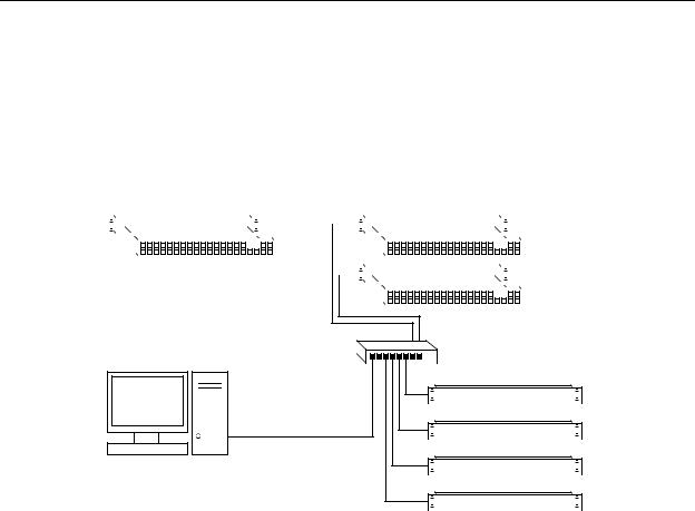
Stand-Alone Routers
Figure 2-1 compares a stand-alone router with a captive panel to a stand-alone router network with remote panel modules:
|
|
|
|
|
|
|
|
|
|
|
|
|
|
|
Remote Panel 1 |
|
|
|
|
|
|
|
|
||||||||
|
|
|
|
|
|
|
|
|
|
|
|
|
|
|
|
|
|
|
|
|
|
|
|
|
|
|
|
|
|
|
|
Standalone Router and |
|
|
|
|
|
|
|
|
|
Remote Panel 2 |
|||||
|
|
|
|
|
|
|
|||||||||
|
|
|
|
|
|
|
|||||||||
|
|
||||||||||||||
“Captive” Control Panel |
|
|
|
|
|
|
|
|
|
|
|||||
|
|
|
|
|
|
|
|
|
|
||||||
|
|
|
|
|
|
|
|
|
|
|
|
|
|
|
|
Networked Routers with Remote Panels
Ethernet Switch
Router 1
PC
Router 2
Router 3
Router 4
Fig. 2-1: Standalone Router vs. a Network of Routers
CRSC Network
A CRSC network has the same topology as a stand-alone network (shown in Figure 2-1), except
(1) the routers and remote panel modules have been configured under CRSC which provides a more elegant solution to system design.
CRSC networks do support the use of CR6400 routers and panels.
NV9000 Network
An NV9000 network supports a larger number of routers. Commands issue from the remote panels to the NV9000 which then dispatches the instructions to the routers. The routers return status to the NV9000 which in turn relays the status to the remote panels.
An NV9000 system can also receive commands from many other control panel types.
CR Series routers can be used with an NV9000 router control system. The NV9000 system extends the capabilities of the compact routers.
An NV9000 network is constructed and operated according to the requirements of the NV9000 router control system. Configuration and control of the routers is entirely within the scope of NV9000-SE Utilities, although you can use CRSC to designate the IP addresses of the compact routers. See NV9000 Router Control Systems (page 178) and Compact Routers in an NV9000 System (page 179).
7
Introduction
Overview
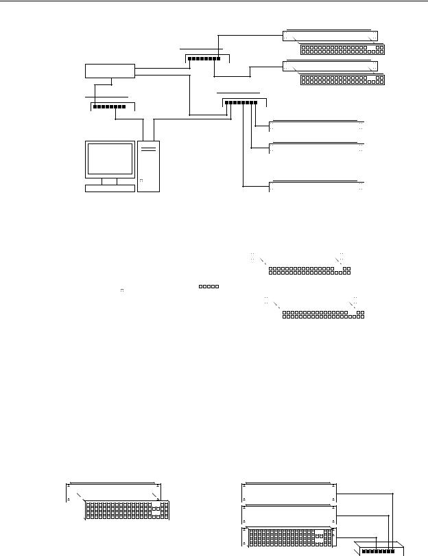
Figure 2-2 shows a sample NV9000 network, one of several possible topologies:
Remote Panel 1
Ethernet
P/R Net 1
Remote Panel 2
NV9000
House Net |
P/R Net 2 |
|
|
|
Ethernet |
Config
PC
Fig. 2-2: NV9000 Network of Routers
|
|
|
|
|
|
|
|
|
|
|
|
|
|
|
|
|
|
|
|
|
|
|
|
|
|
|
|
|
|
|
|
|
|
|
|
|
|
|
|
|
|
|
|
|
|
|
|
|
|
|
|
|
|
|
|
|
|
|
|
|
|
|
|
|
|
|
|
|
|
|
|
Router 1 |
|||||||
|
|
|
|
|
|
|
|
|
|
|
|
|
|
|
|
|
|
|
|
|
|
|
|
|
|
|
|
|
|
|
|
||||||||
|
|
|
|
|
|
|
|
|
|
|
|
|
|
|
|
|
|
|
|
|
|
|
|
|
|
|
|
|
|
|
|
Router 2 |
|||||||
|
|
|
|
|
|
|
|
|
|
|
|
|
|
|
|
|
|
|
|
|
|
|
|
|
|
|
|
|
|
|
|
||||||||
|
|
|
|
|
• • • |
|
|
|
|
|
|
|
|
|
|
|
|
|
|
|
|
|
|
|
|
|
|
|
|
|
|
|
• • • |
||||||
|
|
|
|
|
|
|
|
|
|
|
|
|
|
|
|
|
|
|
|
|
|
|
|
|
|
|
|
|
|
|
|
Router n |
|||||||
|
|
|
|
|
|
|
|
|
|
|
|
|
|
|
|
|
|
|
|
|
|
|
|
|
|
|
|
|
|
|
|
||||||||
|
|
|
|
|
|
|
|
|
|
|
|
|
|
|
|
|
|
|
|
|
|
|
|
|
|
|
|
|
|
|
|
|
|
|
|
|
|
|
|
CQX Networks
Figure 2-3 shows the ways a “clean and quiet” router can be connected:
|
|
|
|
|
|
|
|
|
|
|
|
|
|
|
|
|
|
|
|
|
|
|
|
|
|
|
|
|
|
|
|
|
|
|
|
|
|
|
|
|
|
|
|
|
|
|
|
|
|
|
|
|
|
|
|
|
|
|
|
|
|
|
|
|
|
|
|
|
|
|
|
|
|
|
CQX Router |
|||||||
|
Config |
|
|
|
|
|
|
|
|
|
|
|
|
|
|
|
|
|
|
|
|
|
|
|
|
|
|
|
|
|
|
|
|
|
|
|
|
|
|
|
|
|
|
|
|
|
|
|
|
|
|
|
|
|
|
|
|
|
|
|
|
|
|
|
|
|
|
|
|
|
|
|
||||||||||
|
|
|
|
|
|
|
|
|
|
|
|
|
|
|
|
|
|
|
|
|
|
|
|
|
|
|
|
|
|
|
|
|
|
|
|
|
|
|
|
|
|
|
|
|
|
|
|
|
|
|
|
|
|
|
|
|
|
|
|
|
|
|
|
|
|
|
|
|
|
|
|
|
|
|
Local CQX Panel |
|||||||
|
|
PC |
|
|
|
|
|
|
|
|
|
|
|
|
|
|
|
|
|
|
|
|
|
|
|
|
|
|
|
|
|
|
|
|
|
|
|
|
|
|
|
|
|
|
|
|
|
|
|
|
|
|
|
|
|
|
|
|
|
|
|
|
|
|
|
|
|
|
|
|
|
|
|
|
|
|
||||||
|
|
|
|
|
|
|
|
|
|
|
|
|
|
|
|
|
|
|
|
|
|
|
|
|
|
|
|
|
|
|
|
|
|
|
|
|
|
|
|
|
|
|
|
|
|
|
|
|
|
|
|
|
|
|
|
|
|
|
|
|
|
|
|
|
|
|
|
|
|
|
|
|
|
|
|
|
|
|
|
|||
|
|
|
|
|
|
|
|
|
|
|
|
|
|
|
|
|
|
|
|
|
|
|
|
|
|
|
|
|
|
|
|
Ethernet |
||||||||||||||||||||||||||||||||||||||||||||||||||
|
|
|
|
|
|
|
|
|
|
|
|
|
|
|
|
|
|
|
|
|
|
|
|
|
|
|
|
|
|
|
|
|
|
|
||||||||||||||||||||||||||||||||||||||||||||||||
|
|
|
|
|
|
|
|
|
|
|
|
|
|
|
|
|
|
|
|
|
|
|
|
|
|
|
|
|
|
|
|
|
|
|
|
|
|
|
|
|
|
|
|
|
|
|
|
|
|
|
|
|
|
|
|
|
|
|
|
|
|
|
|
|
|
|
|
|
|
|
|
|
|
|
|
|
|
|
|
|
|
Remote CQX Panel |
|
|
|
|
|
|
|
|
|
|
|
|
|
|
|
|
|
|
|
|
|
|
|
|
|
|
|
|
|
|
|
|
|
|
|
|
|
|
|
|
|
|
|
|
|
|
|
|
|
|
|
|
|
|
|
|
|
|
|
|
|
|
|
|
|
|
|
|
|
|
|
|
|
|
|
|
|
|
|
|
|
|
|
|
|
|
|
|
|
|
|
|
|
|
|
|
|
|
|
|
|
|
|
|
|
|
|
|
|
|
|
|
|
|
|
|
|
|
|
|
|
|
|
|
|
|
|
|
|
|
|
|
|
|
|
|
|
|
|
|
|
|
|
|
|
|
|
|
|
|
|
|
|
|
|
|
|
|
|
|
|
|
|
|
|
|
|
|
|
|
|
|
|
|
|
|
|
|
|
|
|
|
|
|
|
|
|
|
|
|
|
|
|
|
|
|
|
|
|
|
|
|
|
|
|
|
|
|
|
|
|
|
|
|
|
|
|
|
|
|
|
|
|
|
|
|
|
|
|
|
|
|
|
|
|
|
|
|
|
|
|
|
|
|
|
|
|
|
|
|
|
|
|
|
|
|
|
|
|
|
|
|
|
|
|
|
|
|
|
|
|
|
|
|
|
|
|
|
|
|
|
|
|
|
|
|
|
|
|
|
|
|
|
|
|
|
|
|
|
|
|
|
|
|
|
|
|
|
|
|
|
|
|
|
|
|
|
|
|
|
|
|
|
|
|
|
|
|
|
|
|
|
|
|
|
|
|
|
|
|
|
|
|
|
|
|
|
|
|
|
|
|
|
|
|
|
|
|
|
|
|
|
|
|
|
|
|
|
|
|
|
|
|
|
|
|
|
|
|
|
|
|
|
|
|
|
|
|
|
|
|
|
|
|
|
|
|
|
|
|
|
|
|
|
|
|
|
|
|
|
|
|
|
|
|
|
|
|
|
|
|
|
|
|
|
|
|
|
|
|
|
|
|
|
|
|
|
|
|
|
|
|
|
|
|
|
|
|
|
|
|
|
|
|
|
|
|
|
|
|
|
|
|
|
|
|
|
|
|
|
|
|
|
|
|
|
|
|
|
|
|
|
|
|
|
|
|
|
|
|
|
|
|
|
|
|
|
|
|
|
|
|
|
|
|
|
|
|
|
|
|
|
|
|
|
|
|
|
|
|
|
|
|
|
|
|
|
|
|
|
|
|
|
|
|
|
|
|
|
|
|
|
|
|
|
|
|
|
|
|
|
|
|
|
|
|
|
|
|
|
|
|
|
|
|
|
|
|
|
|
|
|
|
|
|
|
|
|
|
|
|
Fig. 2-3: CQX Network
At present, the CQX connections are limited. One CQX router with a local (or captive) CQX panel or a remote CQX panel (or both) can exist on any subnet. (You can have more than one subnet, however.)
At present there is little to configure other than the IP address of the router (and possibly the remote panel module).
CR6400 Stand-Alone Networks
A CR6400 router can operate in stand-alone mode (also known as “default” mode) either as a single router or in a small network.
Figure 2-4 compares a stand-alone CR6400 router with a captive panel to a stand-alone router network with remote panel modules:
Single Standalone Router and
“Captive” Control Panel
Fig. 2-4: CR6400 Usage
Ethernet |
Multiple Standalone Routers |
and “Captive” Control Panel
8
CR Series
User’s Guide
Up to 4 CR6400 routers may be controlled with a single CP6464.
Software
CRSC (Compact Router System Configurator) is a configuration and monitoring tool for compact routers and remote panels. Refer to the CRSC User’s Guide for details.
Benefits
The CR Series Compact Routers offer these benefits:
•Grass Valley performance and quality.
•Very simple operation.
•Low cost.
•Small form factor.
•Easy migration to larger systems.
The Routers
CR6400 Routers
The CR6400 routers are 2RU and about 10” (254mm) deep. The 2 models in the family are visually identical, except for the legend on the I/O cards (3Gig or AES) at the rear.
Figures 2-7 and 2-6 show front and rear views of the CR6400 routers.
Fig. 2-5: Front View of the CR6400 Digital Router
Fig. 2-6: Rear View of the CR6400 Router (CR6464-3Gig shown)
Other CR Series Routers
The routers are slim (35–57mm or 1.38”–2.25”) and mechanically similar, differing principally in the number and type of connectors, and of course, in the signal type supported. The fronts of all the 1RU routers are the same except for their legends and the fronts of all the 2RU routers are the same except for their legends.
The 3Gig, HD, SD, AES, and analog video routers have BNC connectors. The analog audio routers have DB25 connectors (and fans). The machine control routers have RJ-45 connectors.
9

Introduction
Overview
Figures 2-7 through 2-17 show front and rear views of the routers.
Fig. 2-7: Front View of the CR1616-SD Digital Video Router
Fig. 2-8: Rear View of the 16×16 3Gig, HD, SD, or AES Routers
Fig. 2-9: Front View of the CR3232-HD Digital Video Router
Fig. 2-10: Rear View of the 32×32 3Gig, HD, SD, or AES Routers
Fig. 2-11: Rear View of the CR1616-AV Analog Video Router
Fig. 2-12: Rear View of the CR3232-AV Analog Video Router
Fig. 2-13: Rear View of the CR1616-AA Analog Audio Router
10
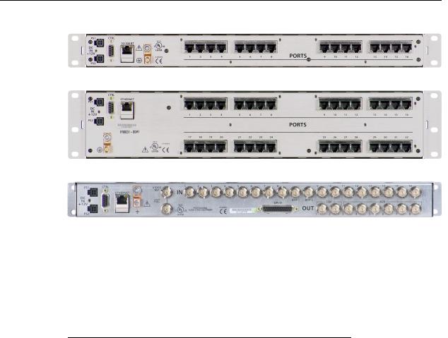
CR Series
User’s Guide
Fig. 2-14: Rear View of the CR3232-AA Analog Audio Router
Fig. 2-15: Rear View of the CR16-PR Machine Control Router
Fig. 2-16: Rear View of the CR32-PR Machine Control Router
Fig. 2-17: Rear View of the 16×2 CQX Routers (3Gig, HD, or SD)
Some routers (e.g., the CR3204-AA or the CR0808-3Gig) have fewer input or output connectors than shown here.
All compact routers save their state in non-volatile memory. Thus, if a power loss occurs, a router can recover almost instantly. All compact routers require a few seconds to initialize.
All compact routers have an serial port (DE9, RS-422 or RS-485).
All compact routers, including CR6400 routers, but not machine control routers, accept these video reference rates:
Composite |
HD Tri-level |
|
|
|
|
|
|
|
|
|
|
|
|
525i / 59.94 |
720p / 23.98 |
1080i |
/ 47.95 |
1080p |
/ 23.98 |
|
(NTSC) |
720p / 24 |
1080i |
/ 48 |
1080p |
/ 24 |
|
625i / 50 |
720p / 25 |
1080i |
/ 50 |
1080p |
/ 25 |
|
(PAL) |
720p |
/ 29.97 |
1080i |
/ 59.94 |
1080p |
/ 29.97 |
|
||||||
|
720p |
/ 30 |
1080i |
/ 60 |
1080p |
/ 30 |
|
720p |
/ 50 |
|
|
1080p |
/ 50 |
|
720p |
/ 59.94 |
|
|
1080p |
/ 59.94 |
|
720p |
/ 60 |
|
|
1080p |
/ 60 |
|
|
|
|
|
|
|
Machine control routers do not receive video reference signals.
11
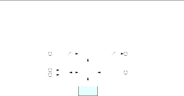
Introduction
Overview
Digital Video Routers
(See CQX Video Routers on page 13 for a discussion of the CQX routers.)
(See CR6400 Routers on page 16 for a discussion of the CR6400 routers.)
Other digital video routers are discussed here.
The 1RU digital video routers have 16×16, 16×4, or 8×8 crosspoint matrices, depending on the model. The 2RU digital video routers have either 32×32 or 32×4 crosspoint matrices.
Figure 2-18 shows a simplified view of the digital video router:
|
|
|
M |
|
|
Crosspoint |
|
N |
|
M = 8, 16, or 32 |
|||
Inputs |
|
|
Switch |
|
Outputs |
||||||||
|
|
|
|
||||||||||
|
|
|
|
|
N = 4, 8, 16, or 32 |
||||||||
(Equalized) |
|
|
|
|
|
(Reclocked) |
|||||||
|
|
|
|
|
|
||||||||
Serial |
|
|
|
|
|
|
|
|
|
|
|
|
|
|
|
μP |
|
|
|
Logic |
|
|
|
|
|
||
|
|
|
|
|
|
|
|
|
|||||
Ethernet |
|
|
|
|
|
|
Video Refer- |
|
|||||
|
|
|
|
|
|
|
|
|
|
||||
|
|
|
|
|
|
|
|
|
|
|
|||
|
|
|
|
|
|
|
|
|
|
|
ence |
|
|
|
|
|
|
|
|
|
|
|
|
|
|
|
|
Control (optional)
Panel
Fig. 2-18: Block Diagram of the Digital Video Router
The video routers perform input equalization and, except for the -NR models, perform reclocking of outputs. The -NR models do not perform reclocking. Router outputs are switched in sync with an external video reference if it is present.
All digital video routers accept bi-level or tri-level video references (sync) and switch according to SMPTE RP168-2002.
3Gig and HD Video Routers
All of the “3Gig” routers support 2.966Gb/s, and 2.97Gb/s video rates as well as a number of HD bit rates and formats. The 3Gig routers reclock at 270Mb/s, 1.483Gb/s, 1.485Gb/s, 2.966Gb/s, and 2.97Gb/s. The 3Gig routers bypass re-clocking for other rates. Video references must be nominally 800mV p-p and bi-level or tri-level in nature.
All of the “HD” routers are SWB (super wide band) routers: they support a wide range of SD and HD bit rates and formats, from 10Mbps to 1.5Gbps. With the exception of the -NR routers, the HD routers reclock at 143, 177, 270, 360, and 540Mb/s and 1.483 and 1.485Gb/s and bypass reclocking for other rates. Video references must be nominally 800mV p-p and bi-level or tri-level in nature. The HD routers support DVB-ASI signals.
SD Video Routers
All of the “SD” routers support a wide range of SD serial data rates from 10Mb/s to 540MB/s. With the exception of the -NR routers, the SD routers reclock at 143, 177, 270, 360, and 540Mb/s. The SD routers support DVB-ASI signals.
NR Video Routers
The HD and SD routers are available in non-reclocking models, such as the CR1616-HD-NR and CR3204-SD-NR. These models are less expensive than the models that have reclocking circuitry and work well with relatively noise-free signals. The reclocking models give better performance in noisy environments.
12

CR Series
User’s Guide
Digital Video Formats
The digital video routers (other than CQX routers) perform video processing for these rates:
Video Format |
Bit Rate |
Remarks |
|
|
|
1080p, 60Hz |
2.97Gb/s |
3Gig |
|
|
|
1080p, 59.94Hz |
2.96Gb/s |
|
|
|
|
1080p, 30Hz |
2.97Gb/s |
|
|
|
|
1080p, 29.97Hz |
2.96Gb/s |
|
|
|
|
1080p, 25Hz |
2.97Gb/s |
|
|
|
|
1080p, 24Hz |
2.97Gb/s |
|
|
|
|
1080p, 23.98Hz |
2.96Gb/s |
|
|
|
|
1080i, 60Hz |
1.485Gb/s |
HD |
|
|
|
1080i, 59.94Hz |
1.483Gb/s |
|
|
|
|
1080i, 50Hz |
1.485Gb/s |
|
|
|
|
1080psf, 30Hz |
1.485Gb/s |
|
|
|
|
1080psf, 29.97Hz |
1.483Gb/s |
|
|
|
|
1080psf, 24 Hz |
1.485Gb/s |
|
|
|
|
1080psf, 23.98 Hz |
1.483Gb/s |
|
|
|
|
720p, 60Hz |
1.485Gb/s |
|
|
|
|
720p, 59.94Hz |
1.483Gb/s |
|
|
|
|
720p, 50Hz |
1.485Gb/s |
|
|
|
|
720p, 30Hz |
1.485Gb/s |
|
|
|
|
720p, 29.97Hz |
1.483Gb/s |
|
|
|
|
720p, 25Hz |
1.485Gb/s |
|
|
|
|
720p, 24Hz |
1.485Gb/s |
|
|
|
|
720p, 23.98Hz |
1.483Gb/s |
|
|
|
|
625i, 50Hz |
270Mb/s |
SD |
|
|
|
525i, 59.94Hz |
270Mb/s |
|
|
|
|
The 3Gig routers can receive all rates listed for HD and SD. The HD routers can also receive video at SD rates.
CQX Video Routers
These 1RU “clean and quiet” video routers switch 16 inputs to 2 “clean and quiet” outputs and 6 auxiliary outputs.
The CQX routers have two crosspoint matrices. The first crosspoint routes 16 normal inputs either to an internal mixer or to the second crosspoint matrix.
The mixer has 2 channels. Each channel mixes two inputs and produces an internal “clean” output. One of the inputs is the signal previously routed to that channel and the other input is the signal that will be routed to that channel. The mixer produces the transition between the previous input and the next input according to the transition type and transition rate currently selected (at a control panel) for the router.
13
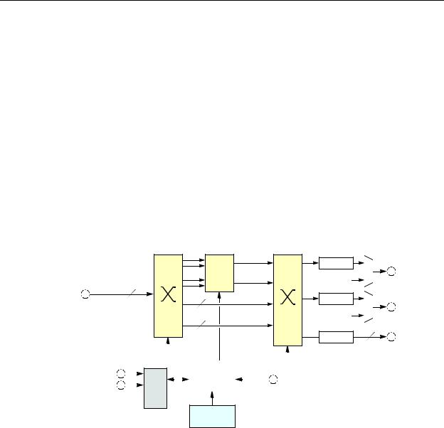
Introduction
Overview
For the SD and HD CQX routers, each input supports video plus 16 embedded audio channels. The mixer transitions both the video and the audio without artifacts.
The 3Gig router supports both level A and level B of the SMPTE 425M standard. The mixer transitions signals of level A, at 1080p, video and audio without artifacts. It handles level B—two 1080i signals in one stream —somewhat differently. It mixes the 16 audio channels of “link A” (from the two inputs) but passes the 16 audio channels of link B (from the two inputs) through to the output unmixed. “Link B” will undergo a cut transition with possible audio artifacts. Although audio for Link B is not processed and undergoes a cut transition, video for Link B is mixed according to the transition type and rate selected on the CQX control panel.
The 3Gig routers do not accept level B’s 2×720p signals at present.
The second crosspoint matrix receives internal signals and produces the CQX outputs 1 and 2 and the 6 auxiliary outputs (which are normal outputs). A multiplexer selects either the clean output or the emergency bypass input. The emergency bypass input is selected only when power fails. (The multiplexer is controlled by a relay that switches to its relaxed position when power fails.)
The router has 16 normal input BNCs, 2 bypass input BNCs, 2 CQX output BNCs, and 6 aux output BNCs.
Figure 2-19 shows a simplified view of the CQX digital video router:
|
|
clean 1 |
Reclock |
|
|
|
Mix 1 |
CQX 1 |
|
|
|
clean 2 |
Em. Bypass 1 |
|
|
|
|
||
|
16 |
Mix 2 |
|
|
|
|
|
||
|
|
|
|
|
Inputs |
6 |
|
Reclock |
CQX 2 |
|
|
Em. Bypass 2 |
||
(Equalized) |
2 |
non-sync |
|
|
|
|
bypass |
Reclock |
6 |
|
|
|
Aux Outputs |
Serial |
|
|
|
|
|
|
|
|
|
|
|
|
|
|
|
|
|
|
|
|
|
|
|
|
|
|
|
|
|
|
|
|
|
|
|
|
μP |
|
|
Logic |
|
|
Video Reference |
||||
|
|
|
|
|
|||||||
Ethernet |
|
|
|
|
|
||||||
|
|
|
|
|
|
|
|
|
|
|
|
GPIO 

Control (optional)
Panel
Fig. 2-19: Block Diagram of the CQX Digital Video Router
The video routers perform input equalization and perform reclocking of outputs. Router outputs are switched in sync with an external video reference if it is present. The video reference also provides sync for embedded audio.
All CQX video routers accept bi-level or tri-level video references (sync) and switch according to SMPTE RP168-2002.
The CQX video routers also provide a bypass path for non-synchronous input signals. If the two sources chosen for a clean and quiet switch are not of the same format, are off-rate, are not at the same frame rate as the video reference, or do not meet the timing window (±3 lines), the video processor enters non-sync bypass mode where the source signal bypasses the video processor and goes straight to the outputs. Thus, the clean and quiet output behaves like an aux output in which there is no video or audio processing—with no transition processing. Switches
14
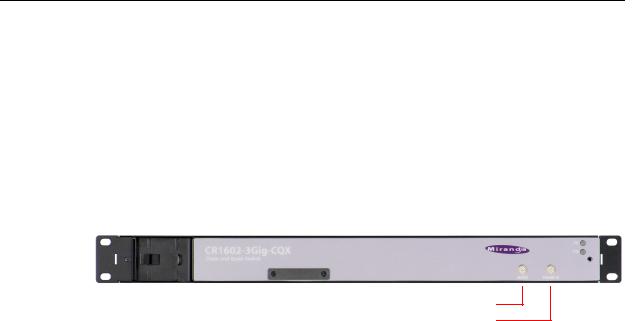
CR Series
User’s Guide
still occur at the specified switchpoint for the video reference, but they will not be “clean and quiet.”
However, if there is no video reference present, the CQX does the cut to the new source as soon as it receives the command from the control panel and does not wait for the switchpoint.
Where one or both of the sources is off-rate or at a frame rate different from that of the video reference, the output will bypass the video processor.
If a clean and quiet output is in a non-sync state but conditions change so that a clean switch is possible, the processor waits for one frame of video before switching to processed video to ensure that the processed video has enough time to pass through the video processing path.
The CQX video routers have a removable fan unit. The fan unit is not visible when a CQX panel is mounted on the router.
|
|
Recessed Fan unit |
16-pos Mode Switch |
|
|
||
|
|
|
16-pos Frame ID Switch |
Fig. 2-20: Front View of the CQX Video Router |
|
||
Customers should have no reason to remove the fan unit.
The CQX video routers have a “mode” switch in addition to the 16-position frame ID switch. Both are 16-position rotary switches that turn with a small screwdriver. The “mode” switch configures the video format of the router. See CQX Routers on page 81 for details.
Set the rotary switch to a position in the range 0–9, A, B, C, or D, according to this table:
Setting |
Format |
|
Setting |
Format |
|
|
|
|
|
0 |
1080i, 59.94 or 60 |
6 |
1080p, 59.94 or 60 |
|
|
1080p, 29.97 or 30 |
7 |
1080p, 50 |
|
|
1080psf, 29.97 or 30 |
|||
|
8 |
2 × 1080i, 59.94 or 60 |
||
|
|
|||
1 |
1080i, 50 |
9 |
2 × 1080i, 50 |
|
|
1080p, 25 |
|
A |
720p, 29.97 or 30 |
|
1080psf, 25 |
|
||
|
|
B |
720p, 25 |
|
|
|
|
||
2 |
525i, 59.94 |
|
C |
720p, 23.98 or 24 |
3 |
625i, 50 |
|
D |
1080p, 23.98 or 24, |
4 |
720p, 59.94 or 60 |
|
|
1080psf, 23.98 or 24 |
|
|
|
||
5 |
720p, 50 |
|
E |
reserved |
|
|
|
F |
reserved |
|
|
|
|
|
Switch positions 6 and 7 correspond to video according to SMPTE 425 level A.
Switch positions 8 and 9 correspond to video according to SMPTE 425 level B.
The default is 1080i, 59.94 Hz (switch setting 0). Positions E and F are not valid positions.
Where a switch setting supports multiple formats, the format is governed by the video reference applied to the router and must be compatible with that reference format.
The CQX routers enter non-sync bypass mode for signals at other rates.
When a control panel is mounted on a router or remote panel module, it conceals the rotary switch. You must remove the control panel when you are setting the rotary switch.
Every time you make a switch change, power-cycle the router or remote panel module.
15
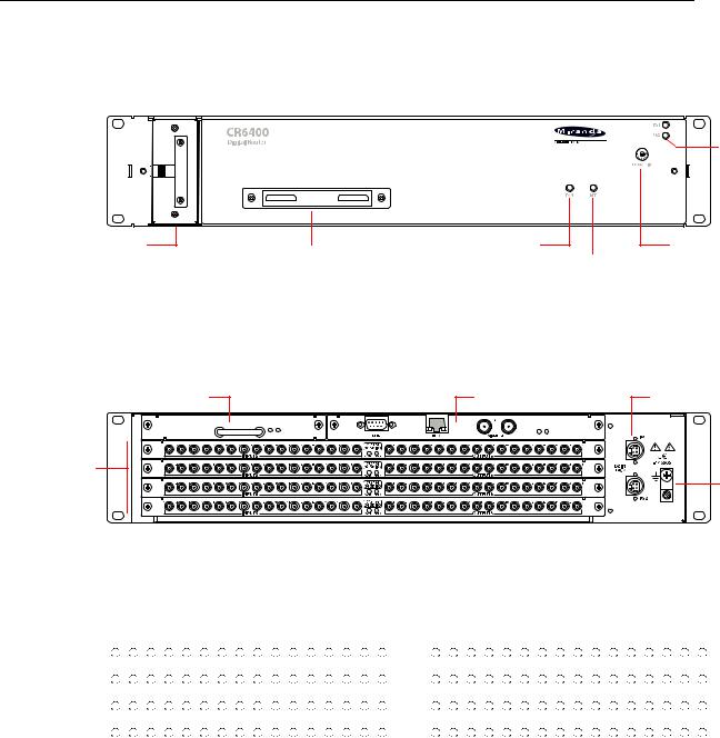
Introduction
Overview
CR6400 Routers
Note: the CR6400 Family Users Guide offers complete detail.
The CR Series routers are 2RU routers. They are about 10” deep to accommodate removable I/O cards. This is a front view of the router:
Power
LEDs
(Removable) Fan Unit |
Connector Cover Plate |
Fan LED |
Rotary Switch |
|
Reference LED |
The CR6464-3Gig and the CR6464-AES routers have the same features at the front. The two routers are distinguished, at the rear, by the labeling on their I/O cards.
The router’s fan module is removable through the front of the router.
At the rear, the CR Series routers have 4 slots for removable I/O cards, and slots for a crosspoint card and a control card (also called a CPU card).
Crosspoint Card |
Control Card |
Power (2) |
I/O Card |
|
|
Slots (4) |
|
Ground |
|
|
Lug |
Each I/O card has 32 ports. There are 16 input ports on the left (as you face the rear of the router) and 16 outputs on the right. The connectors for both the 3Gig card and the AES card are DIN 1.0/ 2.3 connectors (which we usually call “coax” connectors).
The port numbering at the rear of the CR6400 routers is simple:
|
|
|
|
|
|
|
Input |
|
|
|
|
|
|
|
|
|
|
|
|
|
|
Output |
|
|
|
|
|
|
|
||
1 |
2 |
3 |
4 |
5 |
6 |
7 |
8 |
9 |
10 |
11 |
12 |
13 |
14 |
15 |
16 |
1 |
2 |
3 |
4 |
5 |
6 |
7 |
8 |
9 |
10 |
11 |
12 |
13 |
14 |
15 |
16 |
17 |
18 |
19 |
20 |
21 |
22 |
23 |
24 |
25 |
26 |
27 |
28 |
29 |
30 |
31 |
32 |
17 |
18 |
19 |
20 |
21 |
22 |
23 |
24 |
25 |
26 |
27 |
28 |
29 |
30 |
31 |
32 |
33 |
34 |
35 |
36 |
37 |
38 |
39 |
40 |
41 |
42 |
43 |
44 |
45 |
46 |
47 |
48 |
33 |
34 |
35 |
36 |
37 |
38 |
39 |
40 |
41 |
42 |
43 |
44 |
45 |
46 |
47 |
48 |
49 |
50 |
51 |
52 |
53 |
54 |
55 |
56 |
57 |
58 |
59 |
60 |
61 |
62 |
63 |
64 |
49 |
50 |
51 |
52 |
53 |
54 |
55 |
56 |
57 |
58 |
59 |
60 |
61 |
62 |
63 |
64 |
It is 1–64, top-to-bottom, on the left for inputs and 1–64, top-to-bottom, on the right for outputs.
At this revision, the router must contain only 3Gig cards or only AES cards. It may contain from 1 to 4 cards. If the router is populated with 3Gig cards, the router is considered a CR6464-3Gig and switches video. If the router is populated with AES cards, the router is considered a CR6464-AES and switches audio. A router having no cards is considered to be of “undefined” type.
16
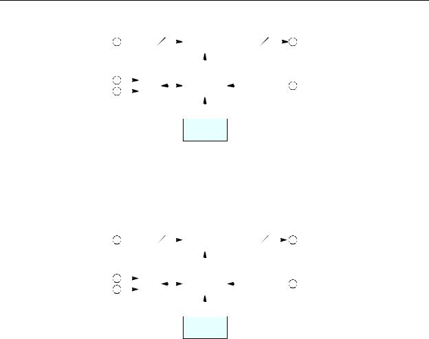
CR Series
User’s Guide
Figure 2-18 shows a simplified block diagram of a CR Series router:
|
64 |
|
|
|
Crosspoint |
64 |
|
|
||||
Inputs |
|
|
Switch |
|
Outputs |
|||||||
|
|
|
|
|
||||||||
(Equalized) |
|
|
|
|
|
(Reclocked) |
||||||
Serial |
|
|
|
|
|
|
|
|
|
|
|
|
|
|
μP |
|
|
|
Logic |
|
|
|
|
||
|
|
|
|
|
|
|
|
|||||
Ethernet |
|
|
|
|
|
|
Video |
|||||
|
|
|
|
|
|
|
|
|
||||
|
|
|
|
|
|
|
|
|
|
|||
|
|
|
|
|
|
|
|
|
|
Reference |
||
|
|
|
|
|
|
|
|
|
|
|
|
|
Control (optional)
Panel
Fig. 2-21: Block Diagram of the CR Series
Analog Video Routers
The 1RU analog video routers have 16×16, 16×4, or 8×8 crosspoints. The 2RU analog video routers have either 32×32 or 32×4 crosspoints.
Figure 2-22 shows a simplified view of an analog video router:
|
|
|
M |
|
|
Crosspoint |
|
N |
|
M = 8, 16 or 32 |
|||
Inputs |
|
|
Switch |
|
Outputs |
||||||||
|
|
|
|
||||||||||
|
|
|
|
|
N = 4, 8, 16, or 32 |
||||||||
Serial |
|
|
|
|
|
|
|
|
|
|
|
|
|
|
|
|
|
|
|
|
|
|
|
|
|
|
|
|
|
μP |
|
|
|
Logic |
|
|
|
|
|
||
|
|
|
|
|
|
|
|
|
|||||
Ethernet |
|
|
|
|
|
|
Video Refer- |
|
|||||
|
|
|
|
|
|
|
|
|
|
||||
|
|
|
|
|
|
|
|
|
|
|
|||
|
|
|
|
|
|
|
|
|
|
|
ence |
|
|
|
|
|
|
|
|
|
|
|
|
|
|
|
|
Control (optional)
Panel
Fig. 2-22: Block Diagram of the Analog Video Router
The analog video routers switch NTSC (525i) or PAL (625i) video signals. The router outputs are switched in sync with an external video reference if it is present.
17
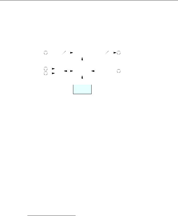
Introduction
Overview
Digital Audio Routers
(See CR6400 Routers on page 16 for a discussion of the CR6400 family’s AES router. This section does not apply to the CR6400 family.)
Other digital audio routers are discussed here.
The 1RU AES routers have 16×16, 16×4, or 8×8 crosspoints. The 2RU AES routers have either 32×32 or 32×4 (stereo) crosspoints.
Figure 2-23 is a simplified view of an AES router:
|
|
|
M |
|
|
Crosspoint |
|
N |
|
M = 8, 16 or 32 |
|||
Inputs |
|
|
Switch |
|
Outputs |
||||||||
|
|
|
|
||||||||||
|
|
|
|
|
N = 4, 8, 16, or 32 |
||||||||
Serial |
|
|
|
|
|
|
|
|
|
|
|
|
|
|
|
|
|
|
|
|
|
|
|
|
|
|
|
|
|
μP |
|
|
|
Logic |
|
|
|
|
|
||
|
|
|
|
|
|
|
|
|
|||||
Ethernet |
|
|
|
|
|
|
Video Refer- |
|
|||||
|
|
|
|
|
|
|
|
|
|
||||
|
|
|
|
|
|
|
|
|
|
|
|||
|
|
|
|
|
|
|
|
|
|
|
ence |
|
|
|
|
|
|
|
|
|
|
|
|
|
|
|
|
Control (optional)
Panel
Fig. 2-23: Block Diagram of the AES Router
If a video reference is present, the router is considered “synchronous” and regenerates output at 48kHz (nominally). The routers also perform a certain amount of signal processing if the input is synchronous. If a video reference is not present, the router is asynchronous and passes input signals straight through without any processing.
In synchronous mode, the router can perform mono routing, in which case, the maximum number of signals is 2N, that is 8, 16, 32, or 64. In asynchronous mode, the router processes AES stereo pairs.
The “AES” routers switch AES3id audio. The AES routers switch in sync with a video reference if one is present.
The two AES modes have different functional characteristics:
•Synchronous mode.
This mode is intended for 48kHz input. However, the router accepts input from 32kHz to 192kHz. The router produces AES3id output at 48kHz using adds and drops,1 as required. If
the input itself is locked to the video reference, no adds or drops occur.
The 16×16 router supports either 16×16 stereo switching or 32×32 mono channel switching (when controlled by an external control system). The 32×32 router supports either 32×32 stereo switching or 64×64 mono channel switching (when controlled by an external control system). Refer to AES Routers on page 181 for more information.
1.When the source and output AES streams are not in sync, AES samples arrive at a rate different from the rate at which they leave the router. Add: when the source is slower than the output, router software occasionally inserts an extra copy of the most recent sample in the output stream until the source and output are back in sync. Drop: when the source is faster than the output, software occasionally does not send the sample(s) to the output until the source and output are back in sync again. Adds and drops are performed on a minute scale, never in large blocks, keeping perceptible distortions to a minimum.
18
Loading...