


8995UPC/DNC/UDX
SD/HD UP/DOWN/CROSS CONVERTER
Instruction Manual
Software Version 1.3.0
071848005 MARCH 2011
Affiliate with the N.V. KEMA in The Netherlands
CERTIFICATE
Certificate Number: 510040.001 The Quality System of:
Thomson Inc, and its worLdwide Grass Valley division affiliates DBA GRASS VALLEY
Headquarters |
15655 SW Greystone Ct. |
10 Presidential Way |
400 Providence Mine Rd |
Beaverton, OR 97006 |
Suite 300 |
Nevada City, CA 95959 |
United States |
Woburn, MA 01801 |
United States |
|
United States |
Kapittelweg 10 |
7140 Baymeadows Way |
2300 So. Decker Lake Blvd. |
4827 HG Breda |
Ste 101 |
Salt Lake City, UT 84119 |
The Nederlands |
Jacksonville, FL 32256 |
United States |
|
United States |
|
Rue du Clos Courtel |
1 rue de l’Hautil |
Technopole Brest-Iroise |
CS 31719 |
Z.I. des Boutries BP 150 |
Site de la Pointe du Diable |
35517 Cesson-Sevigné Cedex |
78702 Conflans-Sainte |
CS 73808 |
France |
Honorine Cedex |
29238 Brest Cedex 3 |
|
France |
France |
40 Rue de Bray |
Spinnereistrasse 5 |
Brunnenweg 9 |
2 Rue des Landelles |
CH-5300 Turgi |
D-64331 Weiterstadt |
35510 Cesson Sevigné |
Switzerland |
Germany |
France |
|
|
Carl-Benz-Strasse 6-8 |
|
|
67105 Schifferstadt |
|
|
Germany |
|
|
Including its implementation, meets the requirements of the standard:
ISO 9001:2008
Scope:
The design, manufacture and support of video and audio hardware and software products and related systems.
This Certificate is valid until: |
June 14, 2012 |
This Certificate is valid as of: |
June 14, 2009 |
Certified for the first time: |
June 14, 2000 |
H. Pierre Sallé
President
KEMA-Registered Quality
The method of operation for quality certification is defined in the KEMA General Terms And Conditions For Quality And Environmental Management Systems Certifications. Integral publication of this certificate is allowed.
KEMA-Registered Quality, Inc. |
Accredited By: |
4377 County Line Road |
ANAB |
Chalfont, PA 18914 |
|
Ph: (215)997-4519 |
|
Fax: (215)997-3809 |
|
CRT 001 073004

8995UPC/DNC/UDX
SD/HD UP/DOWN/CROSS CONVERTER
Instruction Manual
Software Version 1.3.0
071848005 MARCH 2011

Contacting Grass Valley
International |
France |
+800 8080 2020 or +33 1 48 25 20 20 |
|
United States/Canada |
+1 800 547 8949 or +1 530 478 4148 |
Support Centers |
24 x 7 |
|
|
24 x 7 |
|
|
|
Hong Kong, Taiwan, Korea, Macau: +852 2531 3058 Indian Subcontinent: +91 22 24933476 |
|||
|
Asia |
Southeast Asia/Malaysia: +603 7805 3884 Southeast Asia/Singapore: +65 6379 1313 |
|||
Local Support |
|
China: +861 0660 159 450 Japan: +81 3 5484 6868 |
|
||
|
|
|
|
|
|
Centers |
Australia and New Zealand: +61 1300 721 495 |
|
Central/South America: +55 11 5509 3443 |
||
(available |
Middle East: +971 4 299 64 40 Near East and Africa: +800 8080 2020 or +33 1 48 25 20 20 |
||||
during normal |
|
|
|
|
|
business hours) |
|
Belarus, Russia, Tadzikistan, Ukraine, Uzbekistan: +7 095 2580924 225 Switzerland: +41 1 487 80 02 |
|||
|
Europe |
S. Europe/Italy-Roma: +39 06 87 20 35 28 -Milan: +39 02 48 41 46 58 S. Europe/Spain: +34 91 512 03 50 |
|||
|
Benelux/Belgium: +32 (0) 2 334 90 30 Benelux/Netherlands: +31 (0) 35 62 38 42 1 N. Europe: +45 45 96 88 70 |
||||
|
|
Germany, Austria, Eastern Europe: +49 6150 104 444 UK, Ireland, Israel: +44 118 923 0499 |
|||
|
|
|
|
|
|
|
|
Copyright © Grass Valley USA, LLC. All rights reserved. |
|||
|
|
This product may be covered by one or more U.S. and foreign patents. |
|||
Grass Valley Web Site
The www.grassvalley.com web site offers the following:
Online User Documentation — Current versions of product catalogs, brochures, data sheets, ordering guides, planning guides, manuals, and release notes in .pdf format can be downloaded.
FAQ Database — Solutions to problems and troubleshooting efforts can be found by searching our Frequently Asked Questions (FAQ) database.
Software Downloads — Download software updates, drivers, and patches.
|
|
|
|
|
|
|
|
|
|
|
|
|
|
|
|
|
|
|
|
|
|
|
|
|
|
|
|
|
|
|
|
|
|
|
|
|
|
|
|
|
|
|
|
|
|
|
|
|
|
|
|
|
|
|
|
|
|
|
|
|
|
|
|
|
|
|
|
|
|
|
|
|
|
|
|
|
|
|
|
|
|
|
|
|
|
|
|
|
|
|
|
|
|
|
|
|
|
|
|
|
|
|
|
|
|
|
|
|
|
|
|
|
|
|
|
|
|
|
|
|
|
|
|
|
|
|
|
|
|
|
|
|
|
|
|
|
|
|
|
|
|
|
|
|
|
|
|
|
|
|
|
|
|
|
|
|
|
|
|
|
|
|
|
|
|
|
|
|
|
|
|
|
|
|
|
|
|
|
|
|
|
|
|
|
|
|
|
|
|
|
|
|
|
|
|
|
|
|
|
|
|
|
|
|
|
|
|
|
|
|
|
|
|
|
|
|
|
|
|
|
|
|
|
|
|
|
|
|
|
|
|
|
|
|
|
|
|
|
|
|
|
|
|
|
|
|
|
|
|
|
|
|
|
|
|
|
|
|
|
|
|
|
|
|
|
|
|
|
|
|
|
|
|
|
|
|
|
|
|
|
|
|
|
|
|
|
|
|
|
|
|
|
|
|
|
|
|
|
|
|
|
|
|
|
|
|
|
|
|
|
|
|
|
|
|
|
|
|
|
|
|
|
|
|
|
|
|
|
|
|
|
|
|
|
|
|
|
|
|
|
|
|
|
|
|
|
|
|
|
|
|
|
|
|
|
|
|
|
|
|
|
|
|
|
|
|
|
|
|
|
|
|
|
|
|
|
|
|
|
|
|
|
|
|
|
|
|
|
|
|
|
|
|
|
|
|
|
|
|
|
|
|
|
|
|
|
|
|
|
|
|
|
|
|
|
|
|
|
|
|
|
|
|
|
|
|
|
|
|
|
|
|
|
|
|
|
|
|
|
|
|
|
|
|
|
|
|
|
|
|
|
|
|
|
|
|
|
|
|
|
|
|
|
|
|
|
|
|
|
|
|
|
|
|
|
|
|
|
|
|
|
|
|
|
|
|
|
|
|
|
|
|
|
|
|
|
|
|
|
|
|
|
|
|
|
|
|
|
|
|
|
|
|
|
|
|
|
|
|
|
|
|
|
|
|
|
|
|
|
|
|
|
|
|
|
|
|
|
|
|
|
|
|
|
|
|
|
|
|
|
|
|
|
|
|
|
|
|
|
|
|
|
|
|
|
|
|
|
|
|
|
|
|
|
|
|
|
|
|
|
|
|
|
|
|
|
|
|
|
|
|
|
|
|
|
|
|
|
|
|
|
|
|
|
|
|
|
|
|
|
|
|
|
|
|
|
|
|
|
|
|
|
|
|
|
|
|
|
|
|
|
|
|
|
|
|
|
|
|
|
|
|
|
|
|
|
|
|
|
|
|
|
|
|
|
|
|
|
|
|
|
|
|
|
|
|
|
|
|
|
|
|
|
|
|
|
|
|
|
|
|
|
|
|
|
|
|
|
|
|
|
|
|
|
|
|
|
|
|
|
|
|
|
|
|
|
|
|
|
|
|
|
|
|
|
|
|
|
|
|
|
|
|
|
|
|
|
|
|
|
|
|
|
|
|
|
|
|
|
|
|
|
|
|
|
|
|
|
|
|
|
|
|
|
|
|
|
|
|
|
|
|
|
|
|
|
|
|
|
|
|
|
|
|
|
|
|
|
|
|
|
|
|
|
|
|
|
|
|
|
|
|
|
|
|
|
|
|
|
|
|
|
|
|
|
|
|
|
|
|
|
|
|
|
|
|
|
|
|
|
|
|
|
|
|
|
|
|
|
|
|
|
|
|
|
|
|
|
|
|
|
|
|
|
|
|
|
|
|
|
|
|
|
|
|
|
|
|
|
|
|
|
|
|
|
|
|
|
|
|
|
|
|
|
|
|
|
|
|
|
|
|
|
|
|
|
|
|
|
|
|
|
|
|
|
|
|
|
|
|
|
|
|
|
|
|
|
|
|
|
|
|
|
|
|
|
|
|
|
|
|
|
|
|
|
|
|
|
|
|
|
|
|
|
|
|
|
|
|
|
|
|
|
|
|
|
|
|
|
|
|
|
|
|
|
|
|
|
|
|
|
|
|
|
|
|
|
|
|
|
|
|
|
|
|
|
|
|
|
|
|
|
|
|
|
|
|
|
|
|
|
|
|
|
|
|
|
|
4 |
|
|
|
|
|
|
|
|
|
|
|
|
|
|
|
|
|
|
8995UPC/DNC/UDX — Instruction Manual |
|||||||||||||||||
Contents
Preface. . . . . . . . . . . . . . . . . . . . . . . . . . . . . . . . . . . . . . . . . . . . . . . . . . . . . . . . . . . . . . . . . . . . . 7
About This Manual . . . . . . . . . . . . . . . . . . . . . . . . . . . . . . . . . . . . . . . . . . . . . . . . . . . . . 7
8995UPC/DNC/UDX Up/Down/Cross Converter Modules . . . . . . . . . . . . . . . 9
Introduction . . . . . . . . . . . . . . . . . . . . . . . . . . . . . . . . . . . . . . . . . . . . . . . . . . . . . . . . . . . 9 8995UDX Module. . . . . . . . . . . . . . . . . . . . . . . . . . . . . . . . . . . . . . . . . . . . . . . . . . 10 8995UPC Module . . . . . . . . . . . . . . . . . . . . . . . . . . . . . . . . . . . . . . . . . . . . . . . . . . 10 8995DNC Module . . . . . . . . . . . . . . . . . . . . . . . . . . . . . . . . . . . . . . . . . . . . . . . . . 10 System Requirements . . . . . . . . . . . . . . . . . . . . . . . . . . . . . . . . . . . . . . . . . . . . . . . . . . 11 Installation . . . . . . . . . . . . . . . . . . . . . . . . . . . . . . . . . . . . . . . . . . . . . . . . . . . . . . . . . . . 12 Module Placement in the GeckoFlex Frame . . . . . . . . . . . . . . . . . . . . . . . . . . . . . 12 Module Installation Precautions . . . . . . . . . . . . . . . . . . . . . . . . . . . . . . . . . . . . . 13 8995 Module Placement For Genlock Timing . . . . . . . . . . . . . . . . . . . . . . . . . . . . 14 Rear Module Installation . . . . . . . . . . . . . . . . . . . . . . . . . . . . . . . . . . . . . . . . . . . 15 Genlock Submodule Installation . . . . . . . . . . . . . . . . . . . . . . . . . . . . . . . . . . . . . 16 Frame Bus Jumpering . . . . . . . . . . . . . . . . . . . . . . . . . . . . . . . . . . . . . . . . . . . . . . 17 Front Module Installation. . . . . . . . . . . . . . . . . . . . . . . . . . . . . . . . . . . . . . . . . . . 18 Optional Fiber Optics Submodule Installation . . . . . . . . . . . . . . . . . . . . . . . . . 19 Fiber Optic Cleaning Requirement . . . . . . . . . . . . . . . . . . . . . . . . . . . . . . . . . . . 19 Cabling . . . . . . . . . . . . . . . . . . . . . . . . . . . . . . . . . . . . . . . . . . . . . . . . . . . . . . . . . . . . 21 Genlock Loop . . . . . . . . . . . . . . . . . . . . . . . . . . . . . . . . . . . . . . . . . . . . . . . . . . . . . 21 Video Input . . . . . . . . . . . . . . . . . . . . . . . . . . . . . . . . . . . . . . . . . . . . . . . . . . . . . . . 21 Video Outputs . . . . . . . . . . . . . . . . . . . . . . . . . . . . . . . . . . . . . . . . . . . . . . . . . . . . 22 Reclocked Video Output. . . . . . . . . . . . . . . . . . . . . . . . . . . . . . . . . . . . . . . . . . . . 22 Auto Tracking Output. . . . . . . . . . . . . . . . . . . . . . . . . . . . . . . . . . . . . . . . . . . . . . 22 Set Fan Speed to Maximum . . . . . . . . . . . . . . . . . . . . . . . . . . . . . . . . . . . . . . . . . . . . . 23 Power Up . . . . . . . . . . . . . . . . . . . . . . . . . . . . . . . . . . . . . . . . . . . . . . . . . . . . . . . . . . . . 24 Operation Indicator LEDs . . . . . . . . . . . . . . . . . . . . . . . . . . . . . . . . . . . . . . . . . . . . 24 Configuration. . . . . . . . . . . . . . . . . . . . . . . . . . . . . . . . . . . . . . . . . . . . . . . . . . . . . . . . . 26 Configuration Summary. . . . . . . . . . . . . . . . . . . . . . . . . . . . . . . . . . . . . . . . . . . . . . 26 Video Input Selection . . . . . . . . . . . . . . . . . . . . . . . . . . . . . . . . . . . . . . . . . . . . . . 26 Video Timing and Loss of Signal Controls . . . . . . . . . . . . . . . . . . . . . . . . . . . . 26 Signal Conversion . . . . . . . . . . . . . . . . . . . . . . . . . . . . . . . . . . . . . . . . . . . . . . . . . 27 Color Correction. . . . . . . . . . . . . . . . . . . . . . . . . . . . . . . . . . . . . . . . . . . . . . . . . . . 29 Video Processing Adjustments . . . . . . . . . . . . . . . . . . . . . . . . . . . . . . . . . . . . . . 29 Aspect Ratio Controls . . . . . . . . . . . . . . . . . . . . . . . . . . . . . . . . . . . . . . . . . . . . . . 30 Transcoding . . . . . . . . . . . . . . . . . . . . . . . . . . . . . . . . . . . . . . . . . . . . . . . . . . . . . . 33 Audio Processing and Configuration . . . . . . . . . . . . . . . . . . . . . . . . . . . . . . . . . 33 Genlock Controls . . . . . . . . . . . . . . . . . . . . . . . . . . . . . . . . . . . . . . . . . . . . . . . . . . 33 User Settings . . . . . . . . . . . . . . . . . . . . . . . . . . . . . . . . . . . . . . . . . . . . . . . . . . . . . . 33 Fiber Optic Outputs. . . . . . . . . . . . . . . . . . . . . . . . . . . . . . . . . . . . . . . . . . . . . . . . 33 Remote Configuration and Monitoring . . . . . . . . . . . . . . . . . . . . . . . . . . . . . . . . . 34 Local/Remote Jumper. . . . . . . . . . . . . . . . . . . . . . . . . . . . . . . . . . . . . . . . . . . . . . 34 8900NET Module Information . . . . . . . . . . . . . . . . . . . . . . . . . . . . . . . . . . . . . . . 34
8995UPC/DNC/UDX — Instruction Manual |
5 |
Contents
Newton Control Panel Configuration . . . . . . . . . . . . . . . . . . . . . . . . . . . . . . . . 35
Web Browser Interface . . . . . . . . . . . . . . . . . . . . . . . . . . . . . . . . . . . . . . . . . . . . . 36
Status Web Page . . . . . . . . . . . . . . . . . . . . . . . . . . . . . . . . . . . . . . . . . . . . . . . . . . 43
I/O Config Web Page . . . . . . . . . . . . . . . . . . . . . . . . . . . . . . . . . . . . . . . . . . . . . . 46
System Config Web Page . . . . . . . . . . . . . . . . . . . . . . . . . . . . . . . . . . . . . . . . . . . 48
Functional View Web Page . . . . . . . . . . . . . . . . . . . . . . . . . . . . . . . . . . . . . . . . . 53
Video Input Web Page . . . . . . . . . . . . . . . . . . . . . . . . . . . . . . . . . . . . . . . . . . . . . 54
Frame Sync Web Page . . . . . . . . . . . . . . . . . . . . . . . . . . . . . . . . . . . . . . . . . . . . . 55
Color Correction Web Page . . . . . . . . . . . . . . . . . . . . . . . . . . . . . . . . . . . . . . . . . 62
Video Proc Web Page . . . . . . . . . . . . . . . . . . . . . . . . . . . . . . . . . . . . . . . . . . . . . . 63
Transcoding Web Page. . . . . . . . . . . . . . . . . . . . . . . . . . . . . . . . . . . . . . . . . . . . . 66
CC Transcoding. . . . . . . . . . . . . . . . . . . . . . . . . . . . . . . . . . . . . . . . . . . . . . . . . . . 66
VITC Transcoding . . . . . . . . . . . . . . . . . . . . . . . . . . . . . . . . . . . . . . . . . . . . . . . . . 71
Aspect Ratio Web Page . . . . . . . . . . . . . . . . . . . . . . . . . . . . . . . . . . . . . . . . . . . . 73
Video Out Web Page. . . . . . . . . . . . . . . . . . . . . . . . . . . . . . . . . . . . . . . . . . . . . . . 78
Audio Input Status Web Page . . . . . . . . . . . . . . . . . . . . . . . . . . . . . . . . . . . . . . . 79
Audio Delay Web Page . . . . . . . . . . . . . . . . . . . . . . . . . . . . . . . . . . . . . . . . . . . . 80
Audio Gain Web Page . . . . . . . . . . . . . . . . . . . . . . . . . . . . . . . . . . . . . . . . . . . . . 82
Audio Channel Pairing Web Page . . . . . . . . . . . . . . . . . . . . . . . . . . . . . . . . . . . 84
Audio Proc Web Page. . . . . . . . . . . . . . . . . . . . . . . . . . . . . . . . . . . . . . . . . . . . . . 86
Genlock Web Page . . . . . . . . . . . . . . . . . . . . . . . . . . . . . . . . . . . . . . . . . . . . . . . . 88
User Settings Web Page . . . . . . . . . . . . . . . . . . . . . . . . . . . . . . . . . . . . . . . . . . . . 92
Slot Config Web Page . . . . . . . . . . . . . . . . . . . . . . . . . . . . . . . . . . . . . . . . . . . . . . 95
Software Updating . . . . . . . . . . . . . . . . . . . . . . . . . . . . . . . . . . . . . . . . . . . . . . . . . . . . 98
Specifications. . . . . . . . . . . . . . . . . . . . . . . . . . . . . . . . . . . . . . . . . . . . . . . . . . . . . . . . . 99
Status Monitoring. . . . . . . . . . . . . . . . . . . . . . . . . . . . . . . . . . . . . . . . . . . . . . . . . . . . 106
External Frame Alarm . . . . . . . . . . . . . . . . . . . . . . . . . . . . . . . . . . . . . . . . . . . . . . 106
LED Reporting. . . . . . . . . . . . . . . . . . . . . . . . . . . . . . . . . . . . . . . . . . . . . . . . . . . . . 107
Web Browser Interface. . . . . . . . . . . . . . . . . . . . . . . . . . . . . . . . . . . . . . . . . . . . . . 107
SNMP Reporting. . . . . . . . . . . . . . . . . . . . . . . . . . . . . . . . . . . . . . . . . . . . . . . . . . . 107
Service . . . . . . . . . . . . . . . . . . . . . . . . . . . . . . . . . . . . . . . . . . . . . . . . . . . . . . . . . . . . . 108
Power-Up Diagnostic Failure . . . . . . . . . . . . . . . . . . . . . . . . . . . . . . . . . . . . . . . . 108
Troubleshooting . . . . . . . . . . . . . . . . . . . . . . . . . . . . . . . . . . . . . . . . . . . . . . . . . . . 108
Electronic Circuit Breaker . . . . . . . . . . . . . . . . . . . . . . . . . . . . . . . . . . . . . . . . . 108
Module Repair. . . . . . . . . . . . . . . . . . . . . . . . . . . . . . . . . . . . . . . . . . . . . . . . . . . . . 108
Functional Description . . . . . . . . . . . . . . . . . . . . . . . . . . . . . . . . . . . . . . . . . . . . . . . 109
Configuration Summary Table . . . . . . . . . . . . . . . . . . . . . . . . . . . . . . . . . . . . . . . . . 111
Active Format Description. . . . . . . . . . . . . . . . . . . . . . . . . . . . . . . . . . . . . . . . . . . . . 117
AFD Tables . . . . . . . . . . . . . . . . . . . . . . . . . . . . . . . . . . . . . . . . . . . . . . . . . . . . . . . . . 118 Notes on AFD . . . . . . . . . . . . . . . . . . . . . . . . . . . . . . . . . . . . . . . . . . . . . . . . . . . . . . . 118 How to Use the AFD Conversion Tables . . . . . . . . . . . . . . . . . . . . . . . . . . . . . . . . 119 AFD Code Definitions . . . . . . . . . . . . . . . . . . . . . . . . . . . . . . . . . . . . . . . . . . . . . . 123 AFD Definitions For 4:3 Coded Frames. . . . . . . . . . . . . . . . . . . . . . . . . . . . . . 123 AFD Codes For 16:9 Coded Frames . . . . . . . . . . . . . . . . . . . . . . . . . . . . . . . . . 125 AFD Tables – Up Conversion . . . . . . . . . . . . . . . . . . . . . . . . . . . . . . . . . . . . . . . . 127 AFD Tables – Down Conversion . . . . . . . . . . . . . . . . . . . . . . . . . . . . . . . . . . . . . 132
Index. . . . . . . . . . . . . . . . . . . . . . . . . . . . . . . . . . . . . . . . . . . . . . . . . . . . . . . . . . . . . . . . . . . . . 137
6 |
8995UPC/DNC/UDX — Instruction Manual |
Preface
About This Manual
This manual describes the features of a specific 8900 module in the GeckoFlex Signal Processing System family. As part of this module family, it is subject to Safety and Regulatory Compliance described in the GeckoFlex 8900 Series frame documentation (see the GeckoFlex Frames 8900FX/FF/FFN Signal Processing System Instruction Manual).
All Modular product documentation can be found on-line in PDF format at this link:
www.grassvalley.com/docs/modular
8995UPC/DNC/UDX — Instruction Manual |
7 |
Preface
8 |
8995UPC/DNC/UDX — Instruction Manual |
8995UPC/DNC/UDX Up/Down/Cross Converter Modules
Introduction
This manual covers installation, configuration, and operation for the 8995UPC Up Converter, 8995DNC Down Converter, and 8995UDX Up/Down/Cross Converter modules for the GeckoFlex frame.
The 8995 modules provide up/down/cross conversion between broadcast quality SD and HD video. An optional Genlock submodule can be installed for external reference timing for environments requiring video signals to be synchronized with other video sources and processed for video quality.
The following features are available with this module series.
•Two module set including a hot-swappable front and rear module. The rear module requires two rear slots.
•Up to five 8995 modules in the same 2 RU GeckoFlex frame.
•An optional Genlock submodule mounted on the 8995 circuit board accepts an external reference (NTSC/PAL color black or Tri-Level Sync) and manages local and frame bus reference timing to the module.
•Fiber-ready front module accepts a fiber optic submodule option for optical input/output interfaces for all models. Refer to Table 1 on page 19 for the submodules available.
•Frame Sync (with Genlock submodule from two independent frame buses or for local reference) and Delay mode.
•Full featured video proc amp functions including RGB and component color controls, video gain, Y/C clip controls, chroma gain, phase (Hue) and black level control, color space conversion (ITU 601, ITU 709), and Cadence control for setting 3:2 pulldown for video from film.
•Aspect ratio control including mode selection, alignment, top crop and matte color along with Active Format Description (AFD) input and output status reporting and enabling and disabling controls.
8995UPC/DNC/UDX — Instruction Manual |
9 |
Introduction
•Edge enhancement and pixel-level motion adaptive conversion for superb picture quality.
•Color correction controls for RGB gain and offset and gamma settings.
•Powerful handling of embedded audio for channel level and Dolby E stream routing.
•PCM audio processing including audio status reporting, delay, gain, channel pairing, and audio processing controls. Processed audio is then re-embedded into output video stream.
•One auto-tracking output to allow synchronization of audio modules to the Genlock reference.
•VITC time code SD to HD and HD to SD translation supported for same-frame rate (59.94 Hz) or Closed Caption SD to HD or HD to SD translation at same frame rate (59.94 Hz), or output line select for VITC and Closed Caption.
•Minimum delay (1 frame) for low latency live applications all critical format conversions.
•SNMP and product health monitoring is supported through the 8900NET module with applications such as NetCentral.
•Software updating using the NetConfig Networking application and/or microSD card.
8995UDX Module
The 8995UDX provides the full spectrum of up, down, and cross conversion with all of the functionality listed above. Refer to Table 3 on page 28 for a video conversion summary diagram.
8995UPC Module
The 8995UPC is fully featured with 8995 series functionality described above. This module up converts SD video to high quality HD video. Refer to Table 4 on page 28 for a video conversion summary diagram.
8995DNC Module
The 8995DNC is fully featured with 8995 series functionality described above. This module down converts HD video to high quality SD video. Refer to Table 5 on page 29 for a video conversion summary diagram.
10 |
8995UPC/DNC/UDX — Instruction Manual |
System Requirements
System Requirements
The following system requirements are necessary for proper operation of the 8995 Series modules:
•8995 module operation requires the presence of an 8900NET Network Interface module in an 8900FFN GeckoFlex frame for configuration. There are no local front edge configuration controls for this module. When using the web browser interface, the latest version of Internet Explorer is the recommended application. Other web browsers may cause unexpected results.
The latest version of 8900NET (Net Card) software must be at 4.3.0 for proper operation. Check the software version of your 8900NET module by navigating to the Frame Status web page (Figure 16 on page 37) and noting the software version given below the frame graphic. Check the Grass Valley ftp server at this link for the latest 8900NET release:
ftp://ftp.grassvalley.com/modular/8900/8900net/v4.3.0/
•Fans in the front cover must be set at maximum speed. Refer to Set Fan Speed to Maximum on page 23.
•8995 Series release 1.2.0 or later requires version 8 Firmware and version 1 Hardware be installed on the 8900GEN-SM Genlock Submodule if present on any modules. Firmware can be updated with the software update for version 1.2.0 as described in the Release Notes that accompany the version 1.2.0 software release.
To check the version of the 8900GEN-SM submodule, link to the Genlock web page and note the Firmware Version and Hardware Revision reported in the web page header as shown in Figure 54 on page 89.
For software updating information, refer to Software Updating on page 98.
8995UPC/DNC/UDX — Instruction Manual |
11 |
Installation
Installation
The 8995 models consists of a front and rear module set that can only be installed in a GeckoFlex frame. An optional fiber optic submodule is also available for providing fiber inputs or outputs depending on the type of submodule installed. Installation of the 8995 module set is a process of:
1.Determining the placement of the 8995 module based on genlock timing configuration if required,
2.Placing the 8900UDX-R rear module in a rear frame slot (this rear module requires two adjacent rear slot spaces),
3.Installing the Genlock submodule option on the front module if used,
4.Placing the front module in the corresponding front slot,
5.Installing the optional SFP Fiber Optic submodule in the rear module,
6.Cabling the signal ports, and
7.Setting front cover fan speed on 8900NET module to maximum.
Module Placement in the GeckoFlex Frame
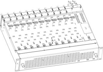
There are ten front and rear cell locations in the 2 RU GeckoFlex frame (Figure 1) to accommodate either audio, analog and digital video modules. The 8995 module set uses the 8900UDX-R rear module that requires two adjacent slots, allowing five 8995 modules per frame.
Figure 1. GeckoFlex Frame
12 |
8995UPC/DNC/UDX — Instruction Manual |
Installation
Module Installation Precautions
Please read and follow the precautions listed below before installing the front and rear modules and any fiber optic option submodules:
•Use standard anti-static procedures during installation. As modules can be installed or removed when the GeckoFlex frame is powered up, before removing the cover, please use an anti-static bracelet tied to a metal part of the frame.
•Install the rear module first, the 8900GEN-SM submodule on the front module (if used), the front module, then the optical submodule option (if used).
•When installing or removing a rear module, loosen or tighten the screws holding the retainer clips to the frame manually with the retainer clip tool provided inside the front cover of the frame or use a 2 mm (5/64”) hex screwdriver. Please do not use an electric screwdriver.
Note On newer 751version GeckoFlex frames, a Rear Retainer Clip removal tool and 2 extra retainer clips and screws for installing them are provided on the inside of the frame cover.
•Make every effort to leave the screws holding the retainer clips in place (do not remove them completely). They are very small and can easily drop into other equipment causing a shorting hazard. (Two turns of the screw should be enough to loosen the screws, 3 turns or more will remove it.)
•When installing a rear module, tighten the screws on the retainer clips just until snug. Do not apply more force than is necessary to seat the rear module. The retainer clip screw torque specification is given in the Mechanical specifications in Table 9 on page 99.
•If using a fiber optic submodule, handle it carefully, use anti-static precautions, and read the Fiber Optic Cleaning Requirement on page 19 before cabling.
8995UPC/DNC/UDX — Instruction Manual |
13 |
Installation
8995 Module Placement For Genlock Timing
Before installing the 8995 module, you will first need to determine if and how you want to use a genlock reference or the available frame reference buses. The genlock timing from an 8900GEN-SM submodule can be utilized in several ways. Refer to the 8900GEN-SM GeckoFlex Genlock Instruction Manual available online for a complete overview of using the genlock reference.
This as well as all other modular product manuals are available online at the following URL on the Grass Valley web site:
http://www.grassvalley.com/docs/modular
In addition to the capability of providing a local external reference to this specific 8995 module with an 8900GEN-SM submodule installed, slots 1 and 3 of the Gecko Flex frame have been specifically designed to distribute an independent frame bus reference transmitted from the 8900GEN-SM submodule mounted on an 8995 module (or other GeckoFlex module with this capability) configured for this purpose. The external reference connected to the corresponding Genlock Loop BNCs can be distributed to other modules in the frame that accept a genlock reference.
If another 8995 module has already been configured and installed for frame bus distribution, you may configure this module’s output timing to lock to the Frame Bus 1 or Frame Bus 2 reference from the other 8995 module. In this case, the 8995 does not require the use of an additional 8900GEN-SM submodule.
The use of the genlock reference is determined by the setting of the Output Timing on the System Config web page of the module and module placement in the frame and jumper configuration as summarized below.
•Local Reference – the 8995 with an 8900GEN-SM submodule can have a local external reference connected to one of the corresponding Genlock Loop BNCs. This external timing reference will be fed to this specific 8995 module only.
•Frame Reference 1 or 2 – when an 8995 with an 8900GEN-SM submodule is installed in slot 1 and/or slot 3, a frame timing bus can be enabled to distribute the external reference connected to the corresponding Genlock Loop BNCs on the rear module to all modules in the frame that can accept a genlock reference. slot 1 provides Frame Bus 1 and slot 3 provides Frame Bus 2.
•Input Video – when no 8900GEN-SM submodule is installed on the 8995, the Output Timing can be set to Input so the output timing will follow the input to the module.
14 |
8995UPC/DNC/UDX — Instruction Manual |
Installation
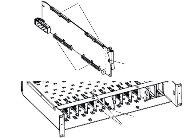
Rear Module Installation
To install the rear module, refer to Figure 2 and the instructions below:
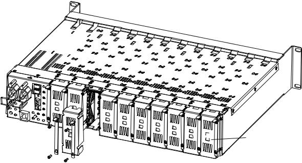
1.To remove a blank rear adapter cover (or a rear module already present), manually loosen the two screws holding each retainer clip on the rear adapter cover or rear module to the frame with the retainer clip tool provided inside the front cover of the frame (newer model frames only) or a 2 mm (5/64”) hex screwdriver. Do not remove the screws.
Note To remove a rear module already installed, follow the same steps. It is helpful to first remove the front module so the rear can be pulled out more easily.
1.After loosening the retainer clip screws, pull up on each retainer and completely remove it, leaving the screws in place.
2.Remove the blank rear adapter cover by inserting needlenose pliers into the slots in the blank cover and pulling it off.
3.Insert the rear module into the empty slot, guiding it carefully.
4.Replace each retainer clip over the two screws on both sides of the module and push down to seat the retainer clip.
5.Tighten the two screws on each retainer clip just until they come into contract with the retainer clip then tighten about a 1/4 turn more. The retainer clips should not bend or be bowed. The rear retainer clip screw torque specification is 4-5 inch-lb/0.45-0.6Nm).
Note All unused rear slots in a GeckoFlex frame should have a blank rear adapter cover installed.
Figure 2. Installing Rear Module (751Version Frame)
_8444 0r23

 Use retainer clip or
needlenose pliers
to pull out blank after removing retainer clips
8995UPC/DNC/UDX — Instruction Manual |
15 |
Installation
Genlock Submodule Installation
The Genlock submodule will ship in a separate package, not installed on the front module.
To install a Genlock submodule, follow these steps:
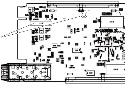
1.Locate the Genlock connector J14, on the back side of the 8995 circuit board (Figure 3).
2.Line up the connector on the submodule, J1, with J14 on the front module and snap the submodule into place making sure the holes in each circuit board line up.
3.To hold the submodule in place, attach the screw provided from the bottom of the front module to the standoff on the submodule circuit board.
Figure 3. Installing Genlock Submodule
Install Genlock submodule on back of circuit board.
Center submodule connector J1 over front module connector J14 and snap in place. From top side
of module, tighten the screw provided to the standoff on the circuit board.
04r1 _ 8480
16 |
8995UPC/DNC/UDX — Instruction Manual |
Installation
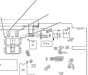
Frame Bus Jumpering
If you will be using this 8995 module to distribute reference Frame Bus 1 (slot 1) or Frame Bus 2 (slot 3), you must set a jumper on the front module circuit board for this purpose before installing the module (Figure 4).
•Frame Bus 1 – to transmit the reference connected to one of the Genlock Loop BNCs on the corresponding rear module on Frame Bus 1, set jumper J11 to ENA (pins 1-2). This module must be installed in slot 1 of the frame and configured on the Genlock web page (see Genlock Web Page on page 88) for Auto in the Drive Frame Reference Bus pulldown.
•Frame Bus 2 – to transmit the reference connected to one of the Genlock Loop BNCs on the corresponding rear module on Frame Bus 2, set jumper J10 to ENA (pins 1-2). This module must be installed in slot 3 of the frame and configured on the Genlock web page (see Genlock Web Page on page 88) for Auto in the Drive Frame Reference Bus pulldown.
Note Both jumpers may be enabled. The module in slot 1 will only read the status of jumper, J11. The module in slot 3 will only read the status of jumper, J10.
Figure 4. Setting Frame Bus Jumpers
For Frame Bus 1 distribution, set
GEN LOCK BUS XMT jumper, J11
Pins 1-2 (ENA) or pins 2-3 (DIS).
|
For Frame Bus 2 distribution, set |
|
GENLOCK BUS XMT jumper, J10 |
Pin 1 |
Pins 1-2 (ENA) or pins 2-3 (DIS). |
|
|
|
Pin 1 |
8480_03r1
8995UPC/DNC/UDX — Instruction Manual |
17 |
Installation
Front Module Installation
After installing the rear module (and Genlock submodule on the front module if required), install the front module as follows:
Note If using a fiber optic submodule, install it through the rear module according to Optional Fiber Optics Submodule Installation on page 19.
1.Remove the front cover of the frame if required.
2.Locate the corresponding front slot.
3.Insert the front module so that the plastic card guides on the module top and bottom edges go over the upper and lower raised rail guides on the right of the top and bottom of the slot(Figure 5).
4.Carefully slide the module into the rear connector.
5.Lock the front module ejector tab into the locking pin.
Note Before removing the front module, first remove the Fiber Optic submodule if present, from the rear module.
Figure 5. Front Module Installation
Card Carriers
Front Module Side View
 Locking Pin
Card Carriers
8431_07r1
 Module installed
Slide top and bottom card carriers on module over top and bottom guides on right of slot.
18 |
8995UPC/DNC/UDX — Instruction Manual |
Installation
Optional Fiber Optics Submodule Installation
After the front and rear modules have been installed, install the SFP Fiber Optic submodule option if being used into the rear module metal cage labeled FIBER (Figure 6 on page 20). The SFP submodule is hot-pluggable and may be installed or removed with power applied to the module.
CAUTION The Fiber Optic submodule is static sensitive. Use static handling precautions when installing or removing the submodule. Fiber connections must be cleaned before installing or cabling as described in Fiber Optic Cleaning Requirement below.
Refer to Table 1 for the correct model of submodule to use with different software versions.
Table 1. Fiber Optic Submodule Summary
Submodule |
Type |
SW1.2.4 and later |
SW 1.2.1 and earlier |
|
|
|
|
SFP-13103G-M1DRX |
Dual Receiver |
X |
– |
|
|
|
|
SFP-13103G-M1DTX |
Dual Transmitter |
X |
– |
|
|
|
|
SFP-13103G-M1TRX |
Transceiver |
X |
– |
|
|
|
|
1310nm-DRL |
Dual Receiver |
X |
X |
|
|
|
|
1310nm-DTL |
Dual Transmitter |
X |
X |
|
|
|
|
1310nm-TRL |
Transceiver |
X |
X |
|
|
|
|
Fiber Optic Cleaning Requirement
Before making any fiber optic cable mating connections, including installation, and after every de-mating cycle, use an industry standard fiber optic cleaning kit, including oil-free compressed air, to clean the fiber connectors and the connectorized fiber end faces. This helps ensure optimum performance of the fiber optic interface. Industry standard fiber optic cleaning kits can be purchased on the web and in electronics stores.
8995UPC/DNC/UDX — Instruction Manual |
19 |
Installation
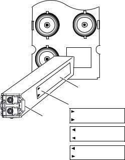
To install the fiber optic submodule:
1.Slide the fiber optic device into the metal fiber cage with the label and handle to the right.
2.Push the device in as far as it will go without forcing it. It will not go completely into the cage.
3.Cable the fiber optic connectors according to the instructions given in
Fiber Optic Video Inputs on page 22 or Fiber Optic Video Outputs on page 22 depending on the type of submodule used.
Figure 6. Installing Fiber Optics Submodule
J7 J8
J9
FIBER
Label
rrow Indicators:
Fiber Optic Receiver
Fiber Optic Transmitter
Fiber Optic Transceiver
8431_03r3
Removing an SFP Submodule
If you need to remove an SFP submodule, snap the handle out and pull the submodule slowly out of the metal cage.
20 |
8995UPC/DNC/UDX — Instruction Manual |
Installation
Cabling
Cabling is done on the rear of the 8900UDX-R module illustrated in Figure 7. Inputs and outputs are also illustrated on the I/0 Config web page (I/O Config Web Page on page 46).
Figure 7. 8995UDX Rear Module
8900UDX-R J2
J1 and J3: |
|
|
Genlock Ref |
J3 |
J4 |
In Loop |
J5 J6
J5: Video Out
J7 J8
J7: Video Out
J9
J9: Video Input
FIBER
 J2: Auto Tracking
Delay Output
 J4: Reclocked
Video Output
 J6: Video Out
 J8: Video Out
 Fiber Inputs/Outputs
(See Fiber Optic Cabling
_01r38480 |
at right) |
|
Fiber Optic Cabling
Fiber Optic Receiver
Fiber Rx 2
Fiber Rx 1
Fiber Optic Transmitter
Fiber Tx 2
Fiber Tx 1
Fiber Optic Transceiver
Fiber Tx 2
Fiber Rx 1
Genlock Loop
BNCs J1 and J3 are looping inputs to the optional Genlock submodule on the 8995 module with an external genlock reference (NTSC/PAL color black or Tri-level sync).
Connect an external reference to J1 or J3 and loop the other input to another device or terminate the unused input.
Video Input
The input to the module can be connected to an electrical coax BNC and up to two fiber optic connectors depending on the fiber optic submodule installed. Only one video input can be active at a time and must be selected on the Video Input web page (page 54).
8995UPC/DNC/UDX — Instruction Manual |
21 |
Installation
Electrical Video Input
To use an electrical input, connect an HD or SD digital video signal to the
Coax input at BNC J9.
Fiber Optic Video Inputs
For fiber optic inputs, a dual receiver or transceiver SFP optical submodule must be installed. Refer to the SFP Fiber Optic Submodule summary table (Table 1 on page 19) for the correct submodule to use. Connect the inputs as illustrated in Figure 7 on page 21. Fiber connections must be cleaned when cabling or after any de-mating cycle. Refer to Fiber Optic Cleaning Requirement on page 19.
Video Outputs
There can be up to six video outputs from the module available at one time, four electrical coax and up to two fiber optic outputs depending on the fiber optic submodule used.
Electrical Outputs
There are four electrical coax video outputs at BNCs J5, J6, J7, and J8 always enabled and available.
Fiber Optic Video Outputs
If an optical transceiver submodule is installed, one fiber optic output (TX2) is available. If an optical dual transmitter submodule is installed, two fiber optic outputs are available TX1 and TX2. Refer to the SFP Fiber Optic Submodule summary table (Table 1 on page 19) for the correct submodule to use. Fiber optic outputs must be enabled on the Fiber Out web page (page 78). Refer to Fiber Optic Cleaning Requirement on page 19 for cleaning fiber optic connections before use.
Reclocked Video Output
One reclocked video output of non-processed input video is provided for looping to other equipment. If a fiber input is being used, the reclocked video from this input will also pass to this output.
Auto Tracking Output
BNC J2 output is an auto tracking delay signal that can be fed to audio modules to synchronize the audio delay to match the delay of the 8995 module.
22 |
8995UPC/DNC/UDX — Instruction Manual |

Set Fan Speed to Maximum
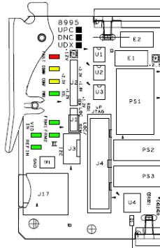
Set Fan Speed to Maximum
Set the front cover fans to maximum speed to maximize the cooling in the frame.
To increase fan cover speed:
1.Remove the front cover of the frame.
2.Remove the 8900NET module (next to the power supplies).
3.Locate Configuration DIP switch S1 (Figure 8).
4.Set position 7 to the right as shown in Figure 8.
5.Return the 8900NET module to the frame and replace the front cover.
Figure 8. Set 8900NET S1 for Maximum Front Cover Fan Speed
Configuration DIP switch S1
S1
12345678
1 2 3 4 5 6 7 8
Fan Speed at maxium
S1
 1
1  2
2  3
3  4
4  5
5  6
6  7
7  8
8
Remote
Override
LED
8900NET
S2
 1
1  2
2  3
3  4
4  5
5  6
6  7
7  8
8
075080000_02r0
8995UPC/DNC/UDX — Instruction Manual |
23 |
Power Up
Power Up
The front LED indicators and configuration switches are illustrated in Figure 9. Upon power-up, the green PWR LED should light and the yellow CONF LED should illuminate for a few seconds for the duration of module initialization.
Note When a media module is first plugged into a GeckoFlex frame, the 8900NET module (if present) may report a momentary fault. This will clear once the media module has booted up.
Operation Indicator LEDs
With factory default configuration and a valid input signal connected, the green PWR and (Figure 9) on the top side of the module front edge should illuminate (refer to Table 2 on page 25 to see the possible operating indicator combinations).
Figure 9. Front Panel LED Indicators
24 |
8995UPC/DNC/UDX — Instruction Manual |
Power Up
|
|
Table 2. Board Edge LED Names and Meaning |
|
|
|
|
|
LED |
Indication |
Condition |
|
|
|
|
|
FAULT |
Off |
Normal operation. |
|
|
|
||
On continuously |
Module has detected an internal fault. |
||
(red) |
|||
|
|
||
Flashing |
Configuration problems. Check inputs and settings. Missing video. |
||
|
|||
|
|
|
|
COMM |
Off |
No activity on frame communication bus. |
|
|
|
||
3 Quick Pulses |
Locate Module command received by the module from a remote control system. |
||
(yellow) |
|||
|
|
||
Short flash |
Activity present on the frame communication bus. |
||
|
|||
|
|
|
|
CONF |
Off |
Module is in normal operating mode. |
|
(yellow) |
On continuously |
Module is initializing, changing operating modes or programming hardware. |
|
|
|
|
|
PWR |
Off |
No power to module or module’s DC/DC converter failed. |
|
(green) |
On continuously |
Normal operation, module is powered. |
|
|
|
|
|
FRM1 |
Off |
Reference frame bus is disabled to frame on Genlock web page or no Genlock submodule is installed in slot 1. |
|
(green) |
On |
Reference frame bus is enabled on Genlock web page and Genlock submodule is installed in slot 1. |
|
|
|
|
|
FRM2 |
Off |
Reference frame bus is disabled to frame on Genlock web page or no Genlock submodule is installed in slot 3. |
|
(green) |
On |
Reference frame bus is enabled on Genlock web page and Genlock submodule is installed in slot 3. |
|
|
|
|
|
VID IN |
Off |
Indicates no valid input signal is being detected. |
|
(green) |
On |
Indicates a valid input signal is being detected. |
|
|
|
|
|
REF IN |
Off |
Indicates no valid reference signal is being detected or signal is not locked. |
|
(green) |
On |
Indicates a valid reference signal is present and locked. |
|
|
|
|
8995UPC/DNC/UDX — Instruction Manual |
25 |
Configuration
Configuration
The 8995 modules can only be configured remotely using the 8900NET network interface GUI or a networked Newton Control Panel.
Refer to the following sections for configuration instructions:
•Configuration Overview (page 26)
•Remote Control and Monitoring (page 34)
•Configuration Parameter Summary (page 111)
Operation of these control types is explained in detail in their respective sections of this manual.
Configuration Summary
This section provides a brief summary of all parameters that can be configured on the 8995 module. Use this section in conjunction with the specific configuration method instructions for each configuration type. Table 13 on page 111 provides a summary in table format of all parameters and their ranges, default values, and remote, local, and control panel function names and locations for setting each value.
Video Input Selection
The video input source (Coax, RX 1, or RX 2) must be selected on the Video Input web page. Fiber optic inputs available depend on the type of fiber optic submodule installed. All inputs can have connections cabled, but only one input can be used at a time.
Video Timing and Loss of Signal Controls
On a 8995 module with an external Frame Sync genlock timing source selected, the following timing adjustments are available:
•Horizontal Timing – adjusts the horizontal delay of the channel output in pixels
•Vertical Timing – adjusts vertical delay in line increments
Also available on the 8995 module are the following controls for setting the output condition when there is a loss of input signal:
•Auto Blue – when Auto Blue is enabled on a channel, the output will automatically freeze to a blue screen when the input signal is lost on the input.
26 |
8995UPC/DNC/UDX — Instruction Manual |
Configuration
•Auto Freeze – when Auto Freeze is enabled on a channel, the output will automatically freeze on the last valid field when the input signal is lost on the input.
•A Manual freeze can be performed at any time with the following two choices:
•Frame
•Field
Note A field freeze provides less resolution and no motion artifacts in the output. In frame mode, the resolution is higher since both fields are present, but the presentation of the two fields can cause motion artifacts.
Signal Conversion
The 8995UDX module performs three main video conversion functions:
•Up Conversion – allows an SD signal input to be converted to an HD output signal in the same time domain (480i/59.94 to 1080i/59.94 or 576i/50 to 1080i/50 for example).
•Down Conversion – allows an HD signal input to be converted to an SD output signal in the same time domain (1080i/59.94 to 480i/59.94 or 1080i/50 to 576i/50 for example).
•Cross Conversion – allows an HD signal input to be cross converted between progressive signal types and interlaced signal types in the same time domain (720p/59.94 to 1080i/59.94 or 1080i/50 to 720p/50 for example).
8995UPC/DNC/UDX — Instruction Manual |
27 |
Configuration
The various up, down, and cross conversion possibilities for all input signal to output signal selections are shown in Table 3 for the 8995UDX.
|
|
Note |
Note that all conversions must occur in the same time domain or they will be |
||||||
|
|
|
invalid. Invalid conditions are grayed out. |
|
|
|
|||
|
|
Table 3. 8995UDX Up, Down, and Cross Conversion |
|
|
|
||||
|
|
|
|
|
|
|
|
|
|
|
|
|
|
|
Output Signal |
|
|
|
|
|
|
|
|
|
|
|
|
|
|
|
|
480i |
720p |
1080i |
1080p |
1080sf |
576i |
720p |
1080i |
|
|
(SD/59.94) |
(59.94) |
(59.94) |
(23.98 |
(23.98 |
(SD/50) |
(50) |
(50) |
|
|
|
|
|
|
|
|
|
|
|
480i |
|
Up |
Up |
Up |
Up |
|
|
|
|
(SD/59.94) |
|
Convert |
Convert |
Convert |
Convert |
|
|
|
|
720p |
Down |
|
Cross |
Cross |
Cross |
|
|
|
|
(59.94) |
Convert |
|
Convert |
Convert |
Convert |
|
|
|
|
1080i |
Down |
Cross |
|
Cross |
Cross |
|
|
|
|
(59.94) |
Convert |
Convert |
|
Convert |
Convert |
|
|
|
|
1080p |
Down |
Cross |
Cross |
|
Cross |
|
|
|
Input |
(23.98 |
Convert |
Convert |
Convert |
|
Convert |
|
|
|
Signal |
1080sf |
Down |
Cross |
Cross |
Cross |
|
|
|
|
|
(23.98 |
Convert |
Convert |
Convert |
Convert |
|
|
|
|
|
576i |
|
|
|
|
|
|
Up |
Up |
|
(SD/50) |
|
|
|
|
|
|
Convert |
Convert |
|
720p |
|
|
|
|
|
Down |
|
Cross |
|
(50) |
|
|
|
|
|
Convert |
|
Convert |
|
1080i |
|
|
|
|
|
Down |
Cross |
|
|
(50) |
|
|
|
|
|
Convert |
Convert |
|
|
|
|
|
|
|
|
|
|
|
Table 4 shows the possible input and output conditions for the 8995UPC
Up Converter module or up conversion on the 8995UDX.
|
|
Table 4. 8995UPC/8995UDX Up Conversion |
|
|
|
|
|||
|
|
|
|
|
|
|
|
|
|
|
|
|
|
|
Output Signal |
|
|
|
|
|
|
|
|
|
|
|
|
|
|
|
|
480i |
720p |
1080i |
1080p |
1080sf |
576i |
720p |
1080i |
|
|
(SD/59.94) |
(59.94) |
(59.94) |
(23.98) |
(23.98) |
(SD/50) |
(50) |
(50) |
|
|
|
|
|
|
|
|
|
|
|
480i |
|
Up |
Up |
Up |
Up |
|
|
|
|
(SD/59.94) |
|
Convert |
Convert |
Convert |
Convert |
|
|
|
|
720p |
|
|
|
|
|
|
|
|
|
(59.94) |
|
|
|
|
|
|
|
|
|
1080i |
|
|
|
|
|
|
|
|
|
(59.94) |
|
|
|
|
|
|
|
|
|
1080p |
|
|
|
|
|
|
|
|
Input |
(23.98) |
|
|
|
|
|
|
|
|
Signal |
1080sf |
|
|
|
|
|
|
|
|
|
(23.98) |
|
|
|
|
|
|
|
|
|
576i |
|
|
|
|
|
|
Up |
Up |
|
(SD/50) |
|
|
|
|
|
|
Convert |
Convert |
|
720p |
|
|
|
|
|
|
|
|
|
(50) |
|
|
|
|
|
|
|
|
|
1080i |
|
|
|
|
|
|
|
|
|
(50) |
|
|
|
|
|
|
|
|
|
|
|
|
|
|
|
|
|
|
28 |
8995UPC/DNC/UDX — Instruction Manual |
Configuration
Table 5 shows the possible input and output conditions for the 8995DNC Down Converter module or down conversion on the 8995UDX.
|
|
Table 5. 8995DNC/8995UDX Down Conversion |
|
|
|
|
|||
|
|
|
|
|
|
|
|
|
|
|
|
|
|
|
Output Signal |
|
|
|
|
|
|
|
|
|
|
|
|
|
|
|
|
480i |
720p |
1080i |
1080p |
1080sf |
576i |
720p |
1080i |
|
|
(SD/59.94) |
(59.94) |
(59.94) |
(23.98) |
(23.98) |
(SD/50) |
(50) |
(50) |
|
|
|
|
|
|
|
|
|
|
|
480i |
|
|
|
|
|
|
|
|
|
(SD/59.94) |
|
|
|
|
|
|
|
|
|
720p |
Down |
|
|
|
|
|
|
|
|
(59.94) |
Convert |
|
|
|
|
|
|
|
|
1080i |
Down |
|
|
|
|
|
|
|
|
(59.94) |
Convert |
|
|
|
|
|
|
|
|
1080p |
Down |
|
|
|
|
|
|
|
Input |
(23.98) |
Convert |
|
|
|
|
|
|
|
Signal |
1080sf |
Down |
|
|
|
|
|
|
|
|
(23.98) |
Convert |
|
|
|
|
|
|
|
|
576i |
|
|
|
|
|
|
|
|
|
(SD/50) |
|
|
|
|
|
|
|
|
|
720p |
|
|
|
|
|
Down |
|
|
|
(50) |
|
|
|
|
|
Convert |
|
|
|
1080i |
|
|
|
|
|
Down |
|
|
|
(50) |
|
|
|
|
|
Convert |
|
|
|
|
|
|
|
|
|
|
|
|
Color Correction
Color correction controls are provided for making RGB gain, offset and gamma correction adjustments. Each color channel can be adjusted separately or a total gain or total gamma can be applied to all channels.
Gamma controls brighten and darken the gray intensity of the signal. Raising the gamma above 1.0, brightens the gray intensity. Lowering the gamma below 1.0, darkens the gray intensity.
Video Processing Adjustments
Component level (Y, Cr, Cb) adjustments are provided in the Video processor for video gain and offset, chroma gain, phase control (hue), and color saturation. Each color component can be adjusted separately or the total gain can be adjusted.
Y/C clipping controls are available in the Video Proc for adjusting the top (white) and bottom (black) luminance levels and the white clipping on chrominance channel of the output signal (C White Clip)
Image enhancement controls include a noise reduction control, edge expansion, extended color space, vertical edge filtering, and a matte edge border.
8995UPC/DNC/UDX — Instruction Manual |
29 |
Configuration
Cadence controls are present for selecting between two modes to handle automatic cadence detection in video created from film. The first (and default) choice is Auto Film/Video (3:2 or 2:2 pull down). Video created from film that has a 1/23.98 Hz capture interval must use a process called 3:2 pull down to produce video fields at 1/59.94 Hz intervals.
If artifacts occur in Auto Film/Video (3:2 or 2:2 pull down mode, automatic cadence detection may be disabled by selecting the second choice, Fixed Video (2:2 pull down) mode. In this mode, the de-interlacer to performs motion-adaptive de-interlacing assuming only a 2:2 cadence in the video, reducing the chance of distortion related to cadence detection.
Aspect Ratio Controls
Aspect ratio controls are provided on this module for changing various characteristics of the output image after an up or down conversion using the mode, alignment, position, and crop controls (when applicable).
The module also detects and reports whether Active Format Description (AFD) information is present on the input/output signal. The AFD Input and Output Status sections report the presence of AFD, the AFD Input and Output Line, the Input and Output Aspect Ratio (4:3 or 16:9), and the AFD Input and Output AFD code.
The AFD Input and Output codes are defined as 4-bit binary numbers. Each 4-bit code describes a video picture in terms of aspect ratio and other characteristics of the active image based on the SMPTE 2016-1:2009 and 2016-3:2009 standards.
When present, AFD processing can be disabled in the AFD Control section if desired. When disabled, AFD reporting information will remain on the web page but will be bypassed when the aspect ratio controls are used. The aspect ratio controls will act on the video output in the same manner as when no AFD is detected or AFD is disabled as described in Aspect Ratio (No AFD or AFD Disabled) on page 31.
The following sections describe using the aspect ratio controls on signals with and without AFD:
Aspect Ratio (AFD Present)
When AFD is present on the input and AFD is enabled, the aspect ratio controls will change the output as defined by specific software programming designed to meet the requirements of the SMPTE 2016-1:2009 and 2016-3:2009 AFD code standards.
AFD input and output codes are defined in the Appendix section: Active Format Description on page 117. This Appendix provides detailed definitions of the binary codes and how the AFD codes respond to the aspect ratio settings made on the web page when AFD is present.
30 |
8995UPC/DNC/UDX — Instruction Manual |
 Loading...